Allgemeine Erdungsempfehlung General grounding ...
Allgemeine Erdungsempfehlung General grounding ...
Allgemeine Erdungsempfehlung General grounding ...

You also want an ePaper? Increase the reach of your titles
YUMPU automatically turns print PDFs into web optimized ePapers that Google loves.
Erdung Grounding Tierra<br />
Das dargestellte Netz besteht aus<br />
einer Transformatorstation als<br />
Stromversorger an dem Ort (0) und<br />
zwei Verbrauchern an den Orten (A)<br />
und (B).<br />
Der Einfachheit halber ist eine<br />
einpolige Darstellung gewählt.<br />
Der Stromrückleiter ist eine Sammelschiene,<br />
die gleichzeitig das Bezugspotential<br />
darstellt. Stellvertretend für<br />
den ohmschen, induktiven und<br />
kapazitiven Widerstand der Sammelschiene<br />
sind die Widerstände RL1 und<br />
RL2 der beiden Teilabschnitte von<br />
(0) bis (A) und von (A) bis (B)<br />
eingezeichnet.<br />
Die Rückströme I1+I2 und I2 verursachen<br />
an diesen Widerständen<br />
Spannungsfälle, die zur Anhebung des<br />
Bezugspotentials um den Wert<br />
δUA = (I1+I2) x RL1 am Punkt (A) und<br />
δUB = (I1+I2) x RL1 + I2 x RL2 am<br />
Punkt (B) führen.<br />
Das darunter liegende Diagramm zeigt<br />
die Verhältnisse als grafische<br />
Darstellung.<br />
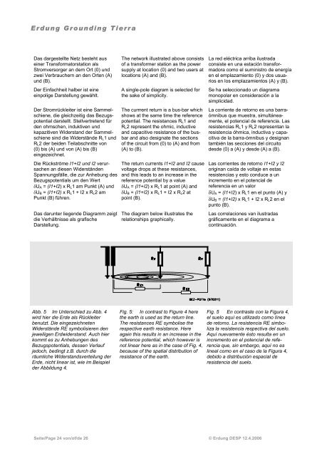
Abb. 5 Im Unterschied zu Abb. 4<br />
wird hier die Erde als Rückleiter<br />
benutzt. Die eingezeichneten<br />
Widerstände RE symbolisieren den<br />
jeweiligen Erdwiderstand. Auch hier<br />
kommt es zu Anhebungen des<br />
Bezugspotentials, dessen Verlauf<br />
jedoch, bedingt z.B. durch die<br />
räumliche Widerstandsverteilung der<br />
Erde, nicht linear ist, wie im Beispiel<br />
der Abbildung 4.<br />
The network illustrated above consists<br />
of a transformer station as the power<br />
supply at location (0) and two users at<br />
locations (A) and (B).<br />
A single-pole diagram is selected for<br />
the sake of simplicity.<br />
The currrent return is a bus-bar which<br />
shows at the same time the reference<br />
potential. The resistances RL1 and<br />
RL2 represent the ohmic, inductive<br />
and capacitive resistance of the busbar<br />
and also designate the sections<br />
of the circuit from (0) to (A) and from<br />
(A) to (B).<br />
The return currents I1+I2 and I2 cause<br />
voltage drops at these resistances,<br />
and this leads to an increase in the<br />
reference potential by a value<br />
δUA = (I1+I2) x RL1 at point (A) and<br />
δUB = (I1+I2) x RL1 + I2 x RL2 at<br />
point (B).<br />
The diagram below illustrates the<br />
relationships graphically.<br />
Fig. 5: In contrast to Figure 4 here<br />
the earth is used as the return line.<br />
The resistances RE symbolise the<br />
respective earth resistance. Here<br />
again this results in an increase in the<br />
reference potential, which however is<br />
not linear here as in the case of Fig. 4,<br />
because of the spatial distribution of<br />
resistance of the earth.<br />
La red eléctrica arriba ilustrada<br />
consiste en una estación transformadora<br />
como el suministro de energía<br />
en el emplazamiento (0) y dos usuarios<br />
en los emplazamientos (A) y (B).<br />
Se ha seleccionado un diagrama<br />
monopolar en consideración a la<br />
simplicidad.<br />
La corriente de retorno es una barraómnibus<br />
que muestra, simultáneamente,<br />
el potencial de referencia. Las<br />
resistencias RL1 y RL2 representan la<br />
resistencia óhmica, inductiva y capacitiva<br />
de la barra-ómnibus y designan<br />
también las secciones del circuito<br />
desde (0) a (A) y desde (A) a (B).<br />
Las corrientes de retorno I1+I2 y I2<br />
originan caída de voltaje en estas<br />
resistencias y esto conduce a un<br />
incremento en el potencial de<br />
referencia en un valor<br />
δUA = (I1+I2) x RL1 en el punto (A) y<br />
δUB = (I1+I2) x RL1 + I2 x RL2 en el<br />
punto (B).<br />
Las correlaciones van ilustradas<br />
gráficamente en el diagrama a<br />
continuación.<br />
Fig. 5 En contraste con la Figura 4,<br />
el suelo aquí es utilizado como línea<br />
de retorno. La resistencia RE simboliza<br />
la resistencia respectiva del suelo.<br />
Aquí nuevamente ésto resulta en un<br />
incremento en el potencial de referencia<br />
que, sin embargo, aquí no es<br />
lineal como en el caso de la Figura 4,<br />
debido a distribución espacial de<br />
resistencia del suelo.<br />
Seite/Page 24 von/of/de 26 © Erdung DESP 12.4.2006