GM Class II Data Bus Interface 2000-2010 GMRC ... - Sonic Electronix
GM Class II Data Bus Interface 2000-2010 GMRC ... - Sonic Electronix
GM Class II Data Bus Interface 2000-2010 GMRC ... - Sonic Electronix

You also want an ePaper? Increase the reach of your titles
YUMPU automatically turns print PDFs into web optimized ePapers that Google loves.
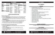
INSTALLATION INSTRUCTIONS FOR PART <strong>GM</strong>RC-01<br />
<strong>GM</strong>RC-01<br />
<strong>GM</strong> <strong>Class</strong> <strong>II</strong> <strong>Data</strong> <strong>Bus</strong> <strong>Interface</strong><br />
<strong>2000</strong>-<strong>2010</strong><br />
APPLICATIONS<br />
See inside front cover<br />
KIT FEATURES<br />
• Provides accessory (12 volt 10 amp)<br />
• Retains RAP (if equipped)<br />
• Used in non-amplified systems or when removing<br />
amplified system<br />
• Retains all warning chimes through onboard speaker<br />
INTERFACE COMPONENTS<br />
• <strong>GM</strong>RC-01 data interface • 10-pin to 24-pin <strong>GM</strong> harness with stripped leads<br />
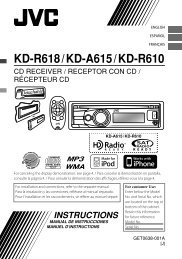
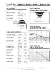
TOOLS REQUIRED<br />
• Cutting tool • Crimping tool • Tape • Connectors (example: butt-connectors, bell caps, etc.)<br />
WIRE<br />
CUTTER<br />
IGNITION<br />
TERMINALS<br />
M3.5<br />
M4 M3<br />
M2.6<br />
M5<br />
ISO<br />
6<br />
2.5<br />
1.5<br />
METRA. THE WORLD’S BEST KITS.<br />
1-800-221-0932<br />
metraonline.com<br />
© COPYRIGHT 2004-2011 METRA ELECTRONICS CORPORATION<br />
REV. 4/25/12
<strong>GM</strong>RC-01<br />
Applications<br />
Note: The <strong>GM</strong>RC-01 is designed to be used in non-amplified <strong>GM</strong> vehicles or in vehicles<br />
that the OEM amplifier has been bypassed; Onstar is not retained in either case. The <strong>GM</strong>RC-01 retains all<br />
the factory warning chimes that would be lost when the OEM radio is removed.<br />
It will also provide a 10 amp 12 volt switched accessory for proper radio operation, and retain the RAP<br />
(Retained Accessory Power) feature if equipped.<br />
Buick<br />
Allure 2005-2009<br />
Century 2004-2005<br />
Lacrosse 2005-2009<br />
Rainier 2004-2007<br />
Rendezvous 2002-2007<br />
Terraza<br />
chevrolet<br />
2005-2008<br />
Avalanche 2003-2006<br />
Cavalier <strong>2000</strong>-2005<br />
Colorado 2004-<strong>2010</strong><br />
Express 2003-2007<br />
Impala <strong>2000</strong>-2005<br />
Malibu 2001-2003<br />
Malibu classic 2004-2005<br />
Monte Carlo <strong>2000</strong>-2005<br />
Silverado pickup classic 2007<br />
Silverado pickup (all models) 2003-2006<br />
SSR 2003-2006<br />
Suburban 2003-2006<br />
Tahoe 2003-2006<br />
Trailblazer 2002-2009<br />
Uplander 2005-2008<br />
Venture van <strong>2000</strong>-2005<br />
<strong>GM</strong>c<br />
Canyon 2004-<strong>2010</strong><br />
Envoy 2002-2009<br />
Savanna van (full size) 2003-2007<br />
Caution: Metra recommends disconnecting the negative battery terminal before beginning<br />
any installation. All accessories, switches, and especially air bag indicator lights must be<br />
plugged in before reconnecting the battery or cycling the ignition.<br />
Note: Refer also to the instructions included with the aftermarket radio.<br />
(<strong>GM</strong>C continued)<br />
Sierra classic 2007<br />
Sierra 2003-2006<br />
Yukon/Yukon XL 2003-2006<br />
huMMer<br />
H3 2006-2009<br />
isuzu<br />
Ascender 2003-2008<br />
I Series pickups 2006-2008<br />
oldsMoBile<br />
Alero 2001-2004<br />
Bravada 2002-2005<br />
Intrigue 2002<br />
Silhouette <strong>2000</strong>-2004<br />
Pontiac<br />
Aztec 2001-2005<br />
Grand Am 2001-2005<br />
Grand Prix 2004-2008<br />
Montana sv6 (Canada) 2005-2008<br />
Montana <strong>2000</strong>-2005<br />
Sunfire <strong>2000</strong>-2005<br />
saaB<br />
9-7X 2005-2009<br />
saturn<br />
Relay 2005-2007
<strong>GM</strong>RC-01<br />
Connections to be made<br />
From the 24-pin harness:<br />
• Connect the Yellow wire to the radio’s 12-volt battery or memory wire.<br />
• Connect the Black wire to the radio’s ground wire.<br />
• Connect the orange/White wire to the illumination wire of the aftermarket radio.<br />
If the aftermarket radio has no illumination wire, tape off the orange/White wire.<br />
• Connect the White wire to the left front positive speaker output of the aftermarket radio.<br />
• Connect the White/Black wire to the left front negative speaker output of the<br />
aftermarket radio.<br />
• Connect the Gray wire to the right front positive speaker output of the aftermarket radio.<br />
• Connect the Gray/Black wire to the right front negative speaker output of the<br />
aftermarket radio.<br />
• Connect the Green wire to the radio’s left rear positive speaker output.<br />
• Connect the Green/Black wire to the radio’s left rear negative speaker output.<br />
• Connect the Purple wire to the radio’s right rear positive speaker output.<br />
• Connect the Purple/Black wire to the radio’s right rear negative speaker output.<br />
• Connect the Blue/White wire to the radio’s antenna turn on wire.<br />
• The orange wire is not used in this application.<br />
From the 10-pin:<br />
• Connect the red wire to the ignition wire of the aftermarket radio.<br />
Installing the <strong>GM</strong>RC-01<br />
• With all connections completed to the aftermarket radio, plug the 24 pin harness into the<br />
vehicles wiring harness.<br />
note: Some minor modifications may be necessary to the sub dash cavity to<br />
accommodate the <strong>GM</strong>RC-01.<br />
• Cycle the key by turning the ignition on then back off, then on again to test the radio.<br />
Testing the <strong>GM</strong>RC-01<br />
• Turn the ignition on if not already, and then turn the radio on to verify that the radio<br />
works. Check balance and fader controls for proper operation.<br />
• Now close all the doors with the radio on and turn the key off. The radio should be still on<br />
until one of the doors is opened.<br />
3
REV. 4/18/12<br />
INSTALLATION INSTRUCTIONS FOR PART <strong>GM</strong>RC-01<br />
iMPortant WarninG<br />
This product includes instructions for installation which must be carefully<br />
followed. The instructions are worded in such a manner to assume<br />
that the installer is capable of completing these type of electronic<br />
installations. If you are unclear as to what you are instructed to do or<br />
believe that you do not understand the instructions so as to properly and<br />
safely complete the installation you should consult a technician who<br />
does have this knowledge and understanding.<br />
Failure to follow these instructions carefully and to install the<br />
interface as described could cause harm to the vehicle or to safety<br />
systems on the vehicle. interference with certain safety systems<br />
could cause harm to persons as well. if you have any questions in<br />
this regard please call the help line or Metra at<br />
1-800-221-0932 for assistance.<br />
KNOWLEDGE IS POWER<br />
Enhance your installation and fabrication skills by<br />
enrolling in the most recognized and respected<br />
mobile electronics school in our industry.<br />
Log onto www.installerinstitute.com or call<br />
800-354-6782 for more information and take steps<br />
toward a better tomorrow.<br />
Metra recommends MECP<br />
certified technicians<br />
METRA. THE WORLD’S BEST KITS.<br />
1-800-221-0932<br />
metraonline.com<br />
© COPYRIGHT 2004-2011 METRA ELECTRONICS CORPORATION
INSTRUCCIONES DE INSTALACIÓN PARA LA PIEZA <strong>GM</strong>RC-01<br />
<strong>GM</strong>RC-01<br />
Interfaz de bus de datos clase <strong>II</strong><br />
para <strong>GM</strong> <strong>2000</strong>-<strong>2010</strong><br />
APLICACIONES<br />
Ver el interior de la cubierta delantera<br />
CARACTERÍSTICAS DEL KIT<br />
• Proporciona accesorio (12 voltios 10 amperes)<br />
• Retiene RAP (si así está equipado)<br />
• Usado en sistemas no amplificados o cuando se quita<br />
el sistema amplificado<br />
• Retiene todos los tonos de advertencia mediante la<br />
bocina incluida<br />
COMPONENTES DE LA INTERFAZ<br />
• Interfaz de datos <strong>GM</strong>RC-01<br />
• Arnés <strong>GM</strong> de 10 pins a 24 pins con contactos desnudos<br />
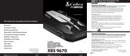
HERRAMIENTAS REQUERIDAS<br />
• Herramientas de corte • Herramienta engarzadora • Cinta<br />
• Conectores (p. ej., conectores a tope, tapas acampanadas, etc.)<br />
WIRE<br />
CUTTER<br />
IGNITION<br />
TERMINALS<br />
M3.5<br />
M4<br />
M2.6<br />
M3<br />
M5<br />
ISO<br />
6<br />
2.5<br />
1.5<br />
METRA. THE WORLD’S BEST KITS.<br />
1-800-221-0932<br />
metraonline.com<br />
© COPYRIGHT 2004-2011 METRA ELECTRONICS CORPORATION<br />
REV. 4/30/12
<strong>GM</strong>RC-01<br />
Aplicaciones<br />
Nota: El <strong>GM</strong>RC-01 está diseñado para usarse en vehículos <strong>GM</strong> no amplificados o en vehículos en los que<br />
se ha anulado el amplificador OEM; OnStar no se retiene en ninguno de estos casos. El <strong>GM</strong>RC-01 retiene<br />
todos los tonos de advertencia de fábrica que se perderían al quitar el radio OEM. También proporciona<br />
un accesorio de 10 amperes y 12 voltios con interruptor para la operación correcta del radio, y que se<br />
retenga la característica de R.A.P. (corriente de accesorios retenida), si se cuenta con este equipamiento.<br />
Buick<br />
Allure 2005-2009<br />
Century 2004-2005<br />
Lacrosse 2005-2009<br />
Rainier 2004-2007<br />
Rendezvous 2002-2007<br />
Terraza<br />
chevrolet<br />
2005-2008<br />
Avalanche 2003-2006<br />
Cavalier <strong>2000</strong>-2005<br />
Colorado 2004-<strong>2010</strong><br />
Express 2003-2007<br />
Impala <strong>2000</strong>-2005<br />
Malibu 2001-2003<br />
Malibu classic 2004-2005<br />
Monte Carlo <strong>2000</strong>-2005<br />
Silverado pickup classic 2007<br />
Silverado pickup (todos los modelos) 2003-2006<br />
SSR 2003-2006<br />
Suburban 2003-2006<br />
Tahoe 2003-2006<br />
Trailblazer 2002-2009<br />
Uplander 2005-2008<br />
Venture van <strong>2000</strong>-2005<br />
<strong>GM</strong>c<br />
Canyon 2004-<strong>2010</strong><br />
Envoy 2002-2009<br />
Savanna van (tamaño completo) 2003-2007<br />
(<strong>GM</strong>C seguido)<br />
Sierra classic 2007<br />
Sierra 2003-2006<br />
Yukon/Yukon XL 2003-2006<br />
huMMer<br />
H3 2006-2009<br />
isuzu<br />
Ascender 2003-2008<br />
I Series pickups 2006-2008<br />
oldsMoBile<br />
Alero 2001-2004<br />
Bravada 2002-2005<br />
Intrigue 2002<br />
Silhouette <strong>2000</strong>-2004<br />
Pontiac<br />
Aztec 2001-2005<br />
Grand Am 2001-2005<br />
Grand Prix 2004-2008<br />
Montana sv6 (Canada) 2005-2008<br />
Montana <strong>2000</strong>-2005<br />
Sunfire <strong>2000</strong>-2005<br />
saaB<br />
9-7X 2005-2009<br />
saturn<br />
Relay 2005-2007<br />
PRECAUCIÓN: Metra recomienda desconectar el terminal negativo de la batería antes de<br />
comenzar cualquier instalación. Todos los accesorios, interruptores y, especialmente, las<br />
luces indicadoras de airbag deben estar enchufados antes de volver a conectar la batería o<br />
comenzar el ciclo de ignición.<br />
Nota: Remítase a las instrucciones incluidas con el radio de postventa.
<strong>GM</strong>RC-01<br />
Conexiones que se deben hacer<br />
desde el arnés de 24 pins:<br />
• Conecte el cable amarillo a la batería de 12 voltios o el cable de memoria del radio.<br />
• Conecte el cable negro con el cable de puesta a tierra del radio.<br />
• Conecte el cable anaranjado/Blanco con el cable de iluminación del radio de mercado<br />
secundario. Si el radio de mercado secundario no tiene cable de iluminación, cubra con<br />
cinta el cable anaranjado/Blanco.<br />
• Conecte el cable Blanco con la salida de la bocina positiva frontal izquierda del radio de<br />
mercado secundario.<br />
• Conecte el cable Blanco/negro con la salida de la bocina negativa frontal izquierda del<br />
radio de mercado secundario.<br />
• Conecte el cable Gris con la salida de la bocina positiva frontal derecha del radio de<br />
mercado secundario.<br />
• Conecte el cable Gris/negro con la salida de la bocina negativa frontal derecha del radio<br />
de mercado secundario.<br />
• Conecte el cable verde con la salida de la bocina positiva izquierda de atrás del radio.<br />
• Conecte el cable verde/negro con la salida de la bocina negativa izquierda de atrás del radio.<br />
• Conecte el cable Púrpura con la salida de la bocina positiva derecha de atrás del radio.<br />
• Conecte el cable Púrpura/negro con la salida de la bocina negativa derecha de<br />
atrás del radio.<br />
• Conecte el cable azul/Blanco con el cable de encendido de la antena.<br />
• El cable anaranjado no se utiliza en esta aplicación.<br />
desde el de 10 pins:<br />
• Conecte el cable rojo con el cable de ignición del radio de mercado secundario<br />
Instalación del <strong>GM</strong>RC-01<br />
• Cuando termine de hacer todas las conexiones en el radio de mercado secundario,<br />
conecte el arnés de 24 pins en el arnés de cables del vehículo.<br />
nota: Pueden requerirse algunas modificaciones menores a la cavidad del sub tablero<br />
para hacer espacio para el <strong>GM</strong>RC-01.<br />
• Cicle la llave prendiendo la ignición, después apagándola, y prendiéndola otra vez para<br />
probar el radio.<br />
Prueba del <strong>GM</strong>RC-01<br />
• Prenda la ignición si no lo ha hecho, y después prenda el radio para probar si funciona.<br />
Revise que funcionen bien los controles de balance e intensidad.<br />
• Ahora cierre todas las puertas con el radio encendido y apague la llave. El radio debe<br />
seguir encendido hasta que se abra una de las puertas.<br />
3
REV. 4/30/12<br />
INSTRUCCIONES DE INSTALACIÓN PARA LA PIEZA <strong>GM</strong>RC-01<br />
advertencia iMPortante<br />
Este producto incluye instrucciones de instalación que deben seguirse<br />
cuidadosamente. Dichas instrucciones están redactadas dando por<br />
supuesto que el instalador es capaz de completar estos tipos de<br />
instalaciones electrónicas. Si tiene dudas respecto de lo que se le<br />
indica que haga o cree que no comprende las instrucciones como para<br />
completar la instalación en forma adecuada y segura, debe consultar a<br />
un técnico que efectivamente tenga estos conocimientos y comprensión.<br />
si no sigue estas instrucciones con cuidado y no instala la<br />
interfaz como se describe, podría provocar daños en el vehículo<br />
o en los sistemas de seguridad del vehículo. la interferencia con<br />
determinados sistemas de seguridad también podría provocar<br />
daños a las personas. si tiene alguna pregunta al respecto,<br />
llame a la línea de ayuda o a metra, al 1-800-221-0932 para<br />
obtener asistencia.<br />
KNOWLEDGE EL CONOCIMIENTO IS POWER ES PODER<br />
Enhance Mejore your sus installation habilidades and de fabrication instalación skills y fabricación by<br />
enrolling inscribiéndose in the most en recognized la escuela and de dispositivos respected<br />
mobile electronics school in our industry.<br />
electrónicos móviles más reconocida y respetada de<br />
Log onto www.installerinstitute.com or call<br />
800-354-6782 nuestra industria. for more Regístrese information en and www.installerinstitute.<br />
take steps<br />
toward com a o better llame tomorrow. al 800-354-6782 para obtener más<br />
información y avance hacia un futuro mejor.<br />
Metra recomienda técnicos con<br />
certificación del Programa de<br />
Certificación en Electrónica Móvil<br />
(Mobile Electronics Certification<br />
Program, MECP).<br />
METRA. THE WORLD’S BEST KITS.<br />
1-800-221-0932<br />
metraonline.com<br />
© COPYRIGHT 2004-2011 METRA ELECTRONICS CORPORATION