CDK-US - bei Berner Torantriebe
CDK-US - bei Berner Torantriebe
CDK-US - bei Berner Torantriebe

You also want an ePaper? Increase the reach of your titles
YUMPU automatically turns print PDFs into web optimized ePapers that Google loves.
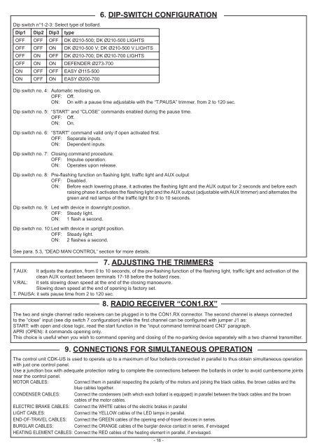
Dip switch n°1-2-3: Select type of bollard.<br />
Dip1 Dip2 Dip3 type<br />
OFF OFF OFF DK Ø210-500; DK Ø210-500 LIGHTS<br />
OFF OFF ON DK Ø210-500 V; DK Ø210-500 V LIGHTS<br />
OFF ON OFF DK Ø210-700; DK Ø210-700 LIGHTS<br />
OFF ON ON DEFENDER Ø273-700<br />
ON OFF OFF EASY Ø115-500<br />
ON OFF ON EASY Ø200-700<br />
6. DIP-SWITCH CONFIGURATION<br />
Dip switch no. 4: Automatic reclosing on.<br />
OFF: Off.<br />
ON: On with a pause time adjustable with the “T.PA<strong>US</strong>A” trimmer, from 2 to 120 sec.<br />
Dip switch no. 5: “START” and “CLOSE” commands enabled during the pause time.<br />
OFF: Off.<br />
ON: On.<br />
Dip switch no. 6: “START” command valid only if open activated fi rst.<br />
OFF: Separate inputs.<br />
ON: Dependent inputs.<br />
Dip switch no. 7: Closing command procedure.<br />
OFF: Impulse operation.<br />
ON: Operates upon release.<br />
Dip switch no. 8: Pre-fl ashing function on fl ashing light, traffi c light and AUX output<br />
OFF: Disabled.<br />
ON: Before each lowering phase, it activates the fl ashing light and the AUX output for 2 seconds and before each<br />
raising phase it activates the fl ashing light and the AUX output (adjustable with AUX trimmer) and alternates the<br />
green and red lamps of the traffi c light for 0 to 10 seconds.<br />
Dip switch no. 9: Led with device in downright position.<br />
OFF: Steady light.<br />
ON: 1 fl ash a second.<br />
Dip switch no. 10: Led with device in upright position.<br />
OFF: Steady light.<br />
ON: 2 fl ashes a second.<br />
See para. 5.3, “DEAD MAN CONTROL” section for more details.<br />
7. ADJ<strong>US</strong>TING THE TRIMMERS<br />
T.AUX: It adjusts the duration, from 0 to 10 seconds, of the pre-fl ashing function of the fl ashing light, traffi c light and activation of the<br />
clean AUX contact between terminals 17-18 before the bollard rises.<br />
V.RAL: it sets slowing down speed at the end of the closing manoeuvre.<br />
Slowing down speed at the end of opening is factory set.<br />
T. PA<strong>US</strong>A: it sets pause time from 2 to 120 sec.<br />
8. RADIO RECEIVER “CON1.RX”<br />
The two and single channel radio receivers can be plugged in to the CON1.RX connector. The second channel is always connected<br />
to the “close” input (see dip switch 7 confi guration) while the fi rst channel can be confi gured with jumper J1 as:<br />
START: with open and close logic, read the start function in the “input command terminal board CN3” paragraph.<br />
APRI (OPEN): it commands opening only.<br />
This choice is useful when you wish to command opening and closing of the no-parking device separately with a two channel transmitter.<br />
9. CONNECTIONS FOR SIMULTANEO<strong>US</strong> OPERATION<br />
The control unit <strong>CDK</strong>-<strong>US</strong> is used to operate up to a maximum of four bollards connected in parallel to thus obtain simultaneous operation<br />
with just one control panel.<br />
Use a junction box with adequate protection rating to complete the connections between the bollards in order to avoid cumbersome joints<br />
near the control panel.<br />
MOTOR CABLES: Connect them in parallel respecting the polarity of the motors and joining the black cables, the brown cables and the<br />
blue cables together.<br />
CONDENSER CABLES: Connect the condensers (with which each bollard is equipped) in parallel between the black cables and the brown<br />
cables of the motor cables.<br />
ELECTRIC BRAKE CABLES: Connect the WHITE cables of the electric brakes in parallel<br />
LIGHT CABLES: Connect the YELLOW cables of the LED lamps in parallel.<br />
END-OF-TRAVEL CABLES: Connect the GREEN cables of the opening end-of-travel devices in series.<br />
BURGLAR CABLES: Connect the ORANGE cables of the burglar device contact in series, if envisaged<br />
HEATING ELEMENT CABLES: Connect the RED cables of the heating element in parallel, if envisaged.<br />
- 16 -