Preaction System with Model DV-5 Deluge Valve - Tyco Fire Products
Preaction System with Model DV-5 Deluge Valve - Tyco Fire Products
Preaction System with Model DV-5 Deluge Valve - Tyco Fire Products

Create successful ePaper yourself
Turn your PDF publications into a flip-book with our unique Google optimized e-Paper software.
Customer Service/Sales:<br />
Technical Services: Tel: http://www.tyco-fireproducts.com<br />
(800) 381-9312 / Fax: (800) 791-5500<br />
Tel: (414) 570-5000 / (800) 558-5236<br />
Fax: (414) 570-5010 / (800) 877-1295<br />
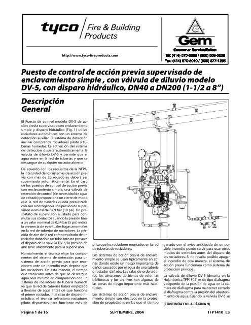
Puesto <strong>Preaction</strong> de control <strong>System</strong> de <strong>with</strong> acción <strong>Model</strong> previa <strong>DV</strong>-5 supervisado <strong>Deluge</strong> <strong>Valve</strong> de<br />
enclavamiento Single Interlock, simple Supervised , con válvula — Wet de Pilot diluvio Actuation modelo<br />
<strong>DV</strong>-5, 1-1/2 thru con disparo 8 Inch (DN40 hidráulico, thruDN40 DN200) a DN200 (1‐1/2 a 8”)<br />
Descripción<br />
General<br />
General<br />
Description<br />
The <strong>Model</strong> <strong>DV</strong>-5 Supervised Single Interlock<br />
Puesto <strong>Preaction</strong> de control <strong>System</strong> modelo <strong>with</strong> <strong>DV</strong>-5 Wet de Pi-<br />
ac-<br />
El ción lot Actuation previa supervisado (Fig. 1) utilizes con enclavamiento<br />
automatic<br />
simple sprinklers y disparo and ahidráulico supplemental (Fig. 1) detection<br />
system. automáticos The supplemental con un sistema detec-<br />
de<br />
utiliza<br />
rociadores detección tion system auxiliar. is comprised El sistema de of wet detección<br />
pilot<br />
auxiliar lines and<br />
comprende pilot sprinklers.<br />
rociadores Actuation<br />
piloto y tuberías<br />
the detection<br />
of<br />
húmedas. system<br />
La activación automatically<br />
del sistema<br />
operates<br />
(releases) the <strong>Model</strong> <strong>DV</strong>-5 <strong>Deluge</strong><br />
<strong>Valve</strong>, allowing water to flow into<br />
de detección dispara automáticamente la<br />
válvula the sprinkler<br />
de diluvio piping<br />
<strong>DV</strong>-5 system<br />
y permite and<br />
que to be<br />
el<br />
agua discharged<br />
entre en from<br />
la red any<br />
de tuberías sprinklers<br />
y que that<br />
se<br />
descargue may be open. de cualquier rociador abierto.<br />
De In acuerdo accordance con los <strong>with</strong> requisitos the requirements<br />
de la NFPA,<br />
la ofintegridad the National de los <strong>Fire</strong> sistemas Protection de acción Association,<br />
con más a preaction de 20 rociadores system employing<br />
deberá ser<br />
previa<br />
supervisada more than 20 automáticamente. automatic sprinklers En el iscaso<br />
to<br />
de have los the puestos sprinkler de control pipingde automatically<br />
acción previa<br />
con supervised enclavamiento monitor simple, the una overall válvula integrity<br />
ofde the control system. (sin necesidad In the case de agua of a<br />
de<br />
retención de Supervised cebado) proporciona Single Interlock un cierre <strong>Preaction</strong> de modo<br />
que <strong>System</strong>, la red ade Riser tuberías Check queda <strong>Valve</strong> presurizada<br />
(that<br />
con does aire not o nitrógeno require a the una use presión of de priming supervisión<br />
water) nominal provides 0,69 an air bar check (10 psi). so Un that presostato<br />
the system<br />
de supervisión can be automatically<br />
ajustado para pressurized<br />
conmutar<br />
sus <strong>with</strong><br />
contactos a nominal<br />
cuando supervisory<br />
la presión baje<br />
air<br />
or nitrogen pressure of 10 psi (0,69<br />
a un valor nominal de 0,34 bar (5 psi) indica<br />
bar). A supervisory low pressure alarm<br />
la switch<br />
presencia that<br />
de is set<br />
eventuales to transfer<br />
fugas its<br />
anormales<br />
contacts<br />
en at<br />
la nominally<br />
red de tuberías 5 psi<br />
de (0,34<br />
rociadores. bar), on<br />
La decreasing<br />
de aire pressure, de la red como is utilized resultado to de indi-<br />
un<br />
pérdida<br />
rociador cate whether dañado there o un tubo are any roto abnormal provoca<br />
el leaks disparo in de thela sprinkler válvula <strong>DV</strong>-5; system la presión piping. de<br />
prisa que los rociadores montados en la red ganado con el aviso anticipado de un posiblties<br />
aire Loss sirve of únicamente air pressure para from la supervisión.<br />
the system<br />
the case of wet pilot actuation, the<br />
also effectively used to protect proper-<br />
de as a result of a damaged sprinkler or<br />
system<br />
tuberías designer<br />
de rociadores.<br />
selects wet pilot<br />
incendio where a<br />
puede pre-alarm<br />
servir para of a<br />
usar possible<br />
otros<br />
Normalmente, el técnico elige los compo-<br />
broken piping will not cause the <strong>DV</strong>-5<br />
sprinklers that will operate sooner than medios fire condition de extinción may antes allowdel time disparo for fire de<br />
Los sistemas de acción previa de enclavamiento<br />
simple se usan típicamente en zonentes<br />
del sistema de detección para un<br />
<strong>Valve</strong> to open — the air pressure is for<br />
the automatic sprinklers chosen for los extinguishment rociadores. Si no byresulta alternate posible suppression<br />
incendio means, de otra priormanera, to a sprinkler el sistema dis-<br />
de<br />
apagar<br />
sistema supervisory<br />
de acción alarm<br />
previa only.<br />
para que reac-<br />
use the sprinkler piping.<br />
el nas donde existe un riesgo importante de<br />
cionen ante un incendio más deprisa que<br />
acción charge. previa In the funcionará event como the fire sistema cannot de<br />
Typically, the system designer selects<br />
daños Supervised causados single por el interlock agua de una preaction tubería<br />
los rociadores. De esta manera, el tiempo<br />
protección otherwiseprincipal.<br />
be extinguished, the preac-<br />
the detection components for a single<br />
o systems rociador are dañado. generally Las salas used de to ordenado-<br />
protect<br />
que transcurra antes de que se descargue<br />
tion sprinkler system will then perform<br />
interlock preaction system that will respond<br />
to a fire sooner than the auto-<br />
bibliotecas water damage y los archivos that might son result algunas from de Hoja técnica TFP1305) es de tipo diafragma<br />
res, areas los where almacenes therede isbienes dangerde ofvalor, serious las La válvula de diluvio <strong>DV</strong>-5 (descrita en la<br />
agua será mínimo en comparación con un<br />
as the primary fire protection system.<br />
sistema de rociadores de tubería húmeda<br />
matic sprinklers. Consequently, the las damaged zonas de automatic riesgo importante sprinklers más or habi-<br />
piping.<br />
Typically, such areas include commarscribed<br />
de diafragma in Technical para mantener Data cerrado<br />
Sheet<br />
y The depende <strong>Model</strong> la <strong>DV</strong>-5 presión <strong>Deluge</strong> de agua <strong>Valve</strong> en la (de-<br />
cá-<br />
ya que la red de tuberías habrá empezado<br />
system will experience a minimal delay tuales.<br />
a llenarse de agua antes de que funcione<br />
in water delivery over that for a wet<br />
puter rooms, storage areas for valuablesistemas<br />
artifacts, de libraries, acción previa and de archives. enclava-<br />
el TFP1305) diafragma contra is a diaphragm la presión del style abasteci-<br />
valve<br />
el primer rociador. In el caso de disparo hidráulico,<br />
system will<br />
Los pipe sprinkler system because the<br />
miento that depends agua. upon Cuando water la válvula pressure <strong>DV</strong>-5 in se<br />
el técnico have essentially<br />
selecciona filled<br />
rociadores miento simple son efectivos en la protec-<br />
<strong>with</strong><br />
the Diaphragm Chamber to hold the<br />
piloto Single interlock preaction systems are<br />
water<br />
dispuestos before a sprinkler<br />
para funcionar operates.<br />
más In<br />
de ción de propiedades en las que el tiempo (CONTINÚA (TEXT EN LA CONTINUED PÁGINA 9)<br />
ON PAGE 9)<br />
Página 1 de 16 Page of 16<br />
SEPTEMBER,<br />
SEPTIEMBRE, 2004 2004<br />
TFP1410_ES<br />
TFP1410
Page Página 2de of16<br />
TFP1410_ES<br />
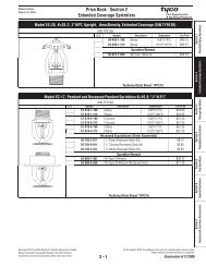
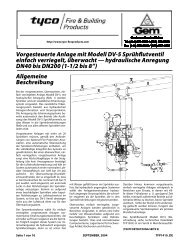
1 - Válvula de diluvio <strong>DV</strong>-5<br />
2 - Válvula de control principal (N.A.)<br />
3 - Válvula de control de la alimentación<br />
de la cámara de diafragma (N.A.)<br />
4 - Actuador manual local<br />
5 - Rociadores automáticos<br />
6 - Rociadores de tuberías de detección<br />
hidráulica (Detección de incendios)<br />
7 - Manómetro del abastecimiento<br />
8 - Manómetro de la cámara de diafragma<br />
9 - Válvula de desagüe del sistema (N.C.)<br />
10 - Válvula de desagüe principal<br />
(N.C.) (mostrada en la parte<br />
posterior de la válvula)<br />
11 - Válvula de cierre automático<br />
de la cámara de diafragma<br />
12 - Presostato de detección de flujo<br />
de agua (mostrado en la parte<br />
posterior de la válvula)<br />
13 - Motor hidráulico de alarma (opcional)<br />
14 - Válvula de retención de control:<br />
15 - Manómetro del suministro de aire<br />
16 - Suministro automático de aire/nitrógeno<br />
17 - Presostato de alarma de baja presión<br />
FIGURA 1 — PARTE 1 DE 2<br />
PUESTO DE CONTROL DE ACCIÓN PREVIA SUPERVISADO DE ENCLAVAMIENTO SIMPLE CON DISPARO HIDRÁULICO<br />
— ESQUEMA DEL SISTEMA (vista frontal) —
TFP1410_ES Page Página 3 of de 16 16<br />
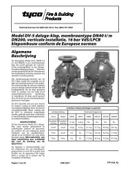
1 - Válvula de diluvio <strong>DV</strong>-5<br />
2 - Válvula de control principal (N.A.)<br />
3 - Válvula de control de la alimentación<br />
de la cámara de diafragma (N.A.)<br />
4 - Actuador manual local (mostrado<br />
en la parte frontal de la válvula)<br />
5 - Rociadores automáticos<br />
6 - Rociadores de tuberías de detección<br />
hidráulica (Detección de incendios)<br />
7 - Manómetro del abastecimiento<br />
(mostrado en la parte<br />
frontal de la válvula)<br />
8 - Manómetro de la cámara de<br />
diafragma (mostrado en la<br />
parte frontal de la válvula)<br />
9 - Válvula de desagüe del sistema (N.C.)<br />
10 - Válvula de desagüe principal (N.C.)<br />
11 - Válvula de cierre automático<br />
de la cámara de diafragma<br />
12 - Presostato de detección del flujo de agua<br />
13 - Motor hidráulico de alarma (opcional)<br />
14 - Válvula de retención de control:<br />
15 - Manómetro de aire de<br />
supervisión (mostrado en la<br />
parte frontal de la válvula)<br />
16 - Suministro automático de aire/nitrógeno<br />
17 - Presostato de alarma de baja presión<br />
FIGURA 1 — PARTE 2 DE 2<br />
PUESTO DE CONTROL DE ACCIÓN PREVIA SUPERVISADO DE ENCLAVAMIENTO SIMPLE CON DISPARO HIDRÁULICO<br />
— ESQUEMA DEL SISTEMA (vista trasera) —
Página de 16<br />
TFP1410_ES<br />
Nº DESCRIPCIÓN CANT. P/N<br />
Page 4 of 16<br />
1 Mánómetro de presión del agua<br />
de 20 bar (300 psi) . . . . . . . . . . . . . . 2 92-343-1-005<br />
2 Válvula de prueba del manómetro<br />
de 1/4” . . . . . . . . . . . . . . . . . . . . . . . . . 1 46-005-1-002<br />
3 Actuador manual modelo MC-1 . 1 52-289-2-001<br />
4 Válvula de desagüe automático<br />
modelo AD-1. . . . . . . . . . . . . . . . . . . 1 52-793-2-004<br />
5 Válvula de cierre automático<br />
modelo ASV-1 . . . . . . . . . . . . . . . . . . 1 92-343-1-021<br />
6 Presostato de detección del flujo<br />
de agua . . . . . . . . . . . . . . (PS10-2A)<br />
1 2571<br />
7 Válvula de bola de 1/2” . . . . . . . . . 2 46-050-1-004<br />
8 Válvula de retención con muelle<br />
de 1/2” . . . . . . . . . . . . . . . . . . . . . . . . . 1 92-322-1-002<br />
9 Filtro en“Y” de 1/2”. . . . . . . . . . . . . . 1 52-353-1-005<br />
10 Válvula de retención de clapeta<br />
oscilante de 3/4”. . . . . . . . . . . . . . . . 1 46-049-1-005<br />
11 Válvula angular de 3/4” . . . . . . . . . 2 46-048-1-005<br />
12 Conector de embudo de goteo . 1 92-211-1-005<br />
13 Ángulo de embudo de goteo . . . 1 92-211-1-003<br />
14 Embudo de goteo . . . . . . . . . . . . . . 1 92-343-1-007<br />
15 Accesorio de venteo de 3/32” . . . 1 92-032-1-002<br />
16 Tubos de 1/4 x 18” . . . . . . . . . . . . . . 1 TS<br />
17 Conector de tubos de 1/2” . . . . . . 1 TS<br />
Nº DESCRIPCIÓN CANT. P/N<br />
18 Tubos de 1/2 x 12” . . . . . . . . . . . . . . 1 TS<br />
19 Tapón de 1/4” . . . . . . . . . . . . . . . . . . 1 TS<br />
20 Tapón de 3/4” . . . . . . . . . . . . . . . . . . 1 TS<br />
21 Unión de 1/2”. . . . . . . . . . . . . . . . . . . 5 TS<br />
22 Unión de 3/4”. . . . . . . . . . . . . . . . . . . 1 TS<br />
23 Codo 90° de 1/4”. . . . . . . . . . . . . . . . 1 TS<br />
24 Codo 90° de 1/2”. . . . . . . . . . . . . . . . 7 TS<br />
25 Codo 90° de 3/4”. . . . . . . . . . . . . . . . 1 TS<br />
26 Codo 90° de 3/4” x 1/2”. . . . . . . . . . 1 TS<br />
27 Té de 1/2” . . . . . . . . . . . . . . . . . . . . . . 3 TS<br />
28 Té de 1/2” x 1/4” x 1/2” . . . . . . . . . . 3 TS<br />
29 Té de 3/4” . . . . . . . . . . . . . . . . . . . . . . 1 TS<br />
30 Té de 3/4” x 1/2” x 3/4” . . . . . . . . . . 2 TS<br />
31 Manguito de unión de 1/4” . . . . . 2 TS<br />
32 Manguito de unión de 1/2” . . . . . 3 TS<br />
33 Manguito de unión de 1/2” x<br />
1‐1/2” . . . . . . . . . . . . . . . . . . . . . . . . . . 11 TS<br />
34 Manguito de unión de 1/2” x 2”. . 1 TS<br />
35 Manguito de unión de 1/2” x<br />
1‐1/2” . . . . . . . . . . . . . . . . . . . . . . . . . . 3 TS<br />
36 Manguito de unión de 1/2” x 5”. . 2 TS<br />
37 Manguito de unión de 1/2” x 7”. . 1 TS<br />
Nº DESCRIPCIÓN CANT. P/N<br />
38 Seleccione el manguito de unión<br />
según la tabla . . . . . . . . . . . . . . . . . . 2 TS<br />
39 Seleccione el manguito de unión<br />
según la tabla . . . . . . . . . . . . . . . . . . 2 TS<br />
40 Manguito de unión de 3/4” x<br />
1‐1/2” . . . . . . . . . . . . . . . . . . . . . . . . . . 6 TS<br />
41 Manguito de unión de 3/4” x 2”. . 1 TS<br />
42 Manguito de unión de 3/4” x 4”. . 1 TS<br />
P1 Mánómetro de presión del aire de<br />
17,5 bar (250 psi) . . . . . . . . . . . . . . . 1 92-343-1-012<br />
P2 Válvula de prueba del manómetro<br />
de 1/4” . . . . . . . . . . . . . . . . . . . . . . . . . 1 46-005-1-002<br />
P3 Presostato de alarma de baja<br />
presión del aire (PS10-2A). . . . . . . 1 2571<br />
P4 Válvula de seguridad de 1/4”. . . . 1 92-343-1-019<br />
P5 Válvula de retención de clapeta<br />
oscilante de 1/2” . . . . . . . . . . . . . . . 1 46-049-1-004<br />
P6 Válvula esférica de 1/2” . . . . . . . . . 1 46-047-1-004<br />
P7 Válvula angular de 3/4” . . . . . . . . . 1 46-048-1-007<br />
P8 Tapón de 1/4” . . . . . . . . . . . . . . . . . . 3 TS<br />
P9 Reducción 1/2” x 1/4” . . . . . . . . . . . 1 TS<br />
P10 Unión de 1/2”. . . . . . . . . . . . . . . . . . . 1 TS<br />
P11 Codo 90° de 1/2”. . . . . . . . . . . . . . . . 1 TS<br />
P12 Cruz de 1/2” . . . . . . . . . . . . . . . . . . . . 1 TS<br />
P13 Té de 1/2” x 1/2” x 1/4” . . . . . . . . . . 1 TS<br />
P14 Té de 1” x 3/4” x 1/2” . . . . . . . . . . . . 1 TS<br />
P15 Manguito de unión de 1/4” x 3”. . 1 TS<br />
P16 Manguito de unión de 1/2” x<br />
1‐1/2” . . . . . . . . . . . . . . . . . . . . . . . . . . 5 TS<br />
P17 Manguito de unión de 1/2” x<br />
1‐1/2” . . . . . . . . . . . . . . . . . . . . . . . . . . 1 TS<br />
P18 Manguito de unión de 3/4” x<br />
1‐1/2” . . . . . . . . . . . . . . . . . . . . . . . . . . 1 TS<br />
P19 Manguito de unión de 1” x 2”. . . . 1 TS<br />
TFP1410<br />
(TINTE<br />
VERDE)<br />
Número<br />
del<br />
manguito<br />
de unión.<br />
Seleccione los tamaños adecuados del<br />
manguito de unión según el diámetro<br />
de la válvula de diluvio <strong>DV</strong>-5<br />
DN40<br />
(1‐1/2”)<br />
DN50<br />
(2”)<br />
38 1/2" mínimo 1/2” x 2“<br />
39 1/2” x 5” 1/2” x 5‐1/2”<br />
UBICACIÓN DE<br />
LA VÁLVULA<br />
DE CONTROL<br />
N.A. OPCIONAL<br />
SUPERVISADA<br />
ELÉCTRICAMENTE<br />
(BVS DE 3/4”)<br />
VÁLVULA DE<br />
RETENCIÓN<br />
PRINCIPAL<br />
(NOTA 2)<br />
NOTAS:<br />
1. El trim está compuesto de<br />
los elementos 1 a -42 más<br />
los elementos P1 a P19 y<br />
los elementos E1a E4.<br />
2. Para los conjuntos DN40<br />
y DN50 (1‐1/2” y 2”) utilice<br />
únicamente la válvula de<br />
retención modelo CV-<br />
1FR de DN50 (2").<br />
3. Todos los accesorios y<br />
manguitos de unión<br />
se sirven galvanizados<br />
(pedido normal).<br />
4. TS: Tornillería simple.<br />
SE MUESTRA LA<br />
VÁLVULA DE DILUVIO<br />
<strong>DV</strong>-5 DN50 (2”) DE<br />
RANURA X RANURA<br />
NOTAS:<br />
5. Identifique la toma de<br />
la válvula en la figura<br />
2 de la TFP1305.<br />
6. Dirija todos los tubos<br />
al embudo de goteo,<br />
elemento 14.<br />
FIGURA 2A — PARTE 1 DE 3<br />
VÁLVULAS DE DILUVIO <strong>DV</strong>-5 DN40 y DN50 (1‐1/2 Y 2”)<br />
PUESTO DE CONTROL DE ACCIÓN PREVIA SUPERVISADO DE ENCLAVAMIENTO SIMPLE CON DISPARO HIDRÁULICO<br />
- TRIM (52-478-X-117)<br />
— DESPIECE —
TFP1410_ES Página de 16 Página TFP1410_ES de 16<br />
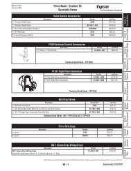
Nº DESCRIPCIÓN CANT. P/N<br />
1 Mánómetro de presión del agua<br />
de 20 bar (300 psi) . . . . . . . . . . . . . . . 2 92-343-1-005<br />
2 Válvula de prueba del manómetro<br />
de 1/4” . . . . . . . . . . . . . . . . . . . . . . . . . . 1 46-005-1-002<br />
3 Actuador manual modelo MC-1 . . 1 52-289-2-001<br />
4 Válvula de desagüe automático<br />
modelo AD-1 1 52-793-2-004<br />
5 Válvula de cierre automático<br />
modelo ASV-1 . . . . . . . . . . . . . . . . . . . 1 92-343-1-021<br />
6 Presostato de alarma de flujo de<br />
agua (PS10-2A) . . . . . . . . . . . . . . . . . . 1 2571<br />
7 Válvula de bola de 1/2” . . . . . . . . . . 2 46-050-1-004<br />
8 Válvula de retención con muelle de<br />
1/2” . . . . . . . . . . . . . . . . . . . . . . . . . . . . . 1 92-322-1-002<br />
9 Filtro en“Y” de 1/2”. . . . . . . . . . . . . . . 1 52-353-1-005<br />
10 Válvula de retención de clapeta<br />
oscilante de 3/4”. . . . . . . . . . . . . . . . . 1 46-049-1-005<br />
11 Válvula angular de 1‐1/4” . . . . . . . . 1 46-048-1-007<br />
12 Conector de embudo de goteo . . 1 92-211-1-005<br />
13 Ángulo de embudo de goteo . . . 1 92-211-1-003<br />
14 Embudo de goteo . . . . . . . . . . . . . . 1 92-343-1-007<br />
15 Accesorio de venteo de 3/32” . . . 1 92-032-1-002<br />
16 Tubos de 1/4 x 18” . . . . . . . . . . . . . . 1 TS<br />
TFP1410<br />
Nº DESCRIPCIÓN CANT. P/N<br />
17 Conector de tubos de 1/2” . . . . . . 1 TS<br />
18 Tubos de 1/2" x 18" 1 TS<br />
19 Tapón de 1/4” . . . . . . . . . . . . . . . . . . 1 TS<br />
20 Tapón de 3/4” . . . . . . . . . . . . . . . . . . 1 TS<br />
21 Unión de 1/2”. . . . . . . . . . . . . . . . . . . 5 TS<br />
22 Unión de 3/4”. . . . . . . . . . . . . . . . . . . 1 TS<br />
23 Codo 90° de 1/4”. . . . . . . . . . . . . . . . 1 TS<br />
24 Codo 90° de 1/2”. . . . . . . . . . . . . . . . 7 TS<br />
25 Codo 90° de 3/4” x 1/2”. . . . . . . . . . 1 TS<br />
26 1‐1/4” 90??SDgr Codo??. . . . . . . . . 1 TS<br />
27 Té de 1/2” . . . . . . . . . . . . . . . . . . . . . . 3 TS<br />
28 Té de 1/2” x 1/4” x 1/2” . . . . . . . . . . 3 TS<br />
29 Té de 3/4” . . . . . . . . . . . . . . . . . . . . . . 1 TS<br />
30 Té de 3/4” x 1/2” x 3/4” . . . . . . . . . . 2 TS<br />
31 Manguito de unión de 1/4” . . . . . 2 TS<br />
32 Manguito de unión de 1/2” . . . . . 2 TS<br />
33 Manguito de unión de 1/2” x 1‐1/2”<br />
13 TS<br />
34 Manguito de unión de 1/2” x 1‐1/2”<br />
1 TS<br />
35 Manguito de unión de 1/2” x 1‐1/2”<br />
1 TS<br />
36 Manguito de unión de 1/2” x 4”. . 1 TS<br />
37 Manguito de unión de 1/2” x 1‐1/2”<br />
1 TS<br />
38 Manguito de unión de 1/2” x 5”. . 1 TS<br />
Nº DESCRIPCIÓN CANT. P/N<br />
39 Manguito de unión de 1/2” x 1‐1/2”<br />
1 TS<br />
40 Manguito de unión de 1/2” x 7”. . 2 TS<br />
41 Manguito de unión de 3/4” x 1‐1/2”<br />
5 TS<br />
42 Manguito de unión de 3/4” x 2”. . 1 TS<br />
43 Manguito de unión de 1‐1/4 x 2” 6 TS<br />
44 Manguito de unión de 1‐1/4 x 4” 1 TS<br />
Page 5 of 16<br />
P1 Mánómetro de presión del aire de<br />
17,5 bar (250 psi) . . . . . . . . . . . . . . . 1 92-343-1-012<br />
P2 Válvula de prueba del manómetro<br />
de 1/4” . . . . . . . . . . . . . . . . . . . . . . . . . 1 46-005-1-002<br />
P3 Presostato de alarma de baja<br />
presión del aire (PS10-2A). . . . . . . 1 2571<br />
P4 Válvula de seguridad de 1/4”. . . . 1 92-343-1-019<br />
P5 Válvula de retención de clapeta<br />
oscilante de 1/2” . . . . . . . . . . . . . . . 1 46-049-1-004<br />
P6 Válvula esférica de 1/2” . . . . . . . . . 1 46-047-1-004<br />
P7 Válvula angular de 1‐1/4” . . . . . . . 1 46-048-1-007<br />
P8 Tapón de 1/4” . . . . . . . . . . . . . . . . . . 3 TS<br />
P9 Reducción 1/2” x 1/4” . . . . . . . . . . . 1 TS<br />
P10Unión de 1/2”. . . . . . . . . . . . . . . . . . . 1 TS<br />
P11Codo 90° de 1/2”. . . . . . . . . . . . . . . . 1 TS<br />
P12Cruz de 1/2” . . . . . . . . . . . . . . . . . . . . 1 TS<br />
P13Té de 1/2” x 1/2” x 1/4” . . . . . . . . . . 1 TS<br />
P14Té de 1‐1/4” x 1‐1/4” x 1/2” . . . . . . 1 TS<br />
P15Manguito de unión de 1/4” x 3”. . 1 TS<br />
P16Manguito de unión de 1/2” x 1‐1/2”<br />
6 TS<br />
P17Manguito de unión de 1‐1/4 x 2” 1 TS<br />
P18Manguito de unión de 1‐1/4 x 3” 1 TS<br />
(TINTE<br />
VERDE)<br />
UBICACIÓN DE<br />
LA VÁLVULA<br />
DE CONTROL<br />
N.A. OPCIONAL<br />
SUPERVISADA<br />
ELÉCTRICAMENTE<br />
(BVS DE 3/4”)<br />
TAPONE<br />
LAS<br />
TOMAS<br />
SIN USAR<br />
VÁLVULA DE<br />
RETENCIÓN<br />
PRINCIPAL<br />
(NOTA 2)<br />
NOTAS:<br />
1. El trim está compuesto de<br />
los elementos 1 a 44 más<br />
los elementos P1 a P18<br />
y los elementos E1 a E4.<br />
2. Utilice únicamente la<br />
válvula de retención<br />
modelo CV-1FR<br />
de DN50 (2")<br />
3. Todos los accesorios y<br />
manguitos de unión<br />
se sirven galvanizados<br />
(pedido normal).<br />
4. TS: Tornillería simple.<br />
SE MUESTRA LA<br />
VÁLVULA DE DILUVIO<br />
<strong>DV</strong>-5 DN80 (3”) DE<br />
RANURA X RANURA<br />
NOTAS:<br />
5. Identifique la toma de<br />
la válvula en la figura<br />
2 de la TFP1305.<br />
6. Dirija todos los tubos<br />
al embudo de goteo,<br />
elemento 14.<br />
FIGURA 2A — PARTE 2 DE 3<br />
VÁLVULAS DE DILUVIO <strong>DV</strong>-5 DN80 (3”)<br />
PUESTO DE CONTROL DE ACCIÓN PREVIA SUPERVISADO DE ENCLAVAMIENTO SIMPLE CON DISPARO HIDRÁULICO<br />
- TRIM (52-478-X-114)<br />
— DESPIECE —
Página de 16<br />
TFP1410_ES<br />
Nº DESCRIPCIÓN CANT. P/N<br />
1 Mánómetro de presión del agua<br />
de 20 bar (300 psi) . . . . . . . . . . . . . . 2 92-343-1-005<br />
2 Válvula de prueba del manómetro<br />
de 1/4” . . . . . . . . . . . . . . . . . . . . . . . . . 1 46-005-1-002<br />
3 Actuador manual modelo MC-1 . 1 52-289-2-001<br />
4 Válvula de desagüe automático<br />
modelo AD-1. . . . . . . . . . . . . . . . . . . 1 52-793-2-004<br />
5 Válvula de cierre automático<br />
modelo ASV-1 . . . . . . . . . . . . . . . . . . 1 92-343-1-021<br />
6 Presostato de alarma de flujo de<br />
agua (PS10-2A) . . . . . . . . . . . . . . . . . 1 2571<br />
7 Válvula de bola de 1/2” . . . . . . . . . 2 46-050-1-004<br />
8 Válvula de retención con muelle<br />
de 1/2” . . . . . . . . . . . . . . . . . . . . . . . . . 1 92-322-1-002<br />
9 Filtro en“Y” de 1/2”. . . . . . . . . . . . . . 1 52-353-1-005<br />
10 Válvula de retención de clapeta<br />
oscilante de 3/4”. . . . . . . . . . . . . . . . 1 46-049-1-005<br />
11 Sin usar . . . . . . . . . . . . . . . . . . . . . . . . 0 N/A<br />
12 Válvula angular de 2” . . . . . . . . . . . 1 46-048-1-009<br />
13 Conector de embudo de goteo . 1 92-211-1-005<br />
14 Ángulo de embudo de goteo . . . 1 92-211-1-003<br />
15 Embudo de goteo . . . . . . . . . . . . . . 1 92-343-1-007<br />
16 Accesorio de venteo de 3/32” . . . 1 92-032-1-002<br />
17 Tubos de 1/4" x 24" 1 TS<br />
18 Conector de tubos de 1/2” . . . . . . 1 TS<br />
19 Tubos de 1/2 x 24” . . . . . . . . . . . . . . 1 TS<br />
20 Tapón de 1/4” . . . . . . . . . . . . . . . . . . 1 TS<br />
21 Tapón de 3/4” . . . . . . . . . . . . . . . . . . 1 TS<br />
22 Unión de 1/2”. . . . . . . . . . . . . . . . . . . 5 TS<br />
23 Unión de 1”. . . . . . . . . . . . . . . . . . . . . 1 TS<br />
Nº DESCRIPCIÓN CANT. P/N<br />
24 Codo 90° de 1/4”. . . . . . . . . . . . . . . . 1 TS<br />
25 Codo 90° de 1/2”. . . . . . . . . . . . . . . . 7 TS<br />
26 Té de 1/2” . . . . . . . . . . . . . . . . . . . . . . 3 TS<br />
27 Té de 1/2” x 1/4” x 1/2” . . . . . . . . . . 3 TS<br />
28 Té de 3/4” x 1/2” x 3/4” . . . . . . . . . . 2 TS<br />
29 1” x 1/2” 90??SDgr Codo??. . . . . . . 1 TS<br />
30 Té de 1” x 3/4” x 1” . . . . . . . . . . . . . . 1 TS<br />
31 2” 90??SDgr Codo??. . . . . . . . . . . . . 1 TS<br />
32 Manguito de unión de 1/4” . . . . . 2 TS<br />
33 Manguito de unión de 1/2” . . . . . 2 TS<br />
34 Manguito de unión de 1/2” x<br />
1‐1/2” . . . . . . . . . . . . . . . . . . . . . . . . . . 10 TS<br />
35 Manguito de unión de 1/2” x<br />
1‐1/2” . . . . . . . . . . . . . . . . . . . . . . . . . . 3 TS<br />
36 Manguito de unión de 1/2” x 3”. . 1 TS<br />
37 Manguito de unión de 1/2” x 5”. . 2 TS<br />
38 Manguito de unión de 1/2” x 6”. . 1 TS<br />
39 Manguito de unión de 1/2” x 7”. . 2 TS<br />
40 Seleccione el manguito de unión<br />
según la tabla . . . . . . . . . . . . . . . . . . 2 TS<br />
41 Seleccione el manguito de unión<br />
según la tabla . . . . . . . . . . . . . . . . . . 2 TS<br />
42 Seleccione el manguito de unión<br />
según la tabla . . . . . . . . . . . . . . . . . . 2 TS<br />
43 Manguito de unión de 3/4” x<br />
1‐1/2” . . . . . . . . . . . . . . . . . . . . . . . . . . 1 TS<br />
Nº DESCRIPCIÓN CANT. P/N<br />
44 Manguito de unión de 3/4” x 2”. . 1 TS<br />
45 Seleccione el manguito de unión<br />
según la tabla . . . . . . . . . . . . . . . . . . 2 TS<br />
46 Manguito de unión de 1”. . . . . . . . 2 TS<br />
47 Manguito de unión de 1” x 3”. . . . 1 TS<br />
48 Sin usar . . . . . . . . . . . . . . . . . . . . . . . . 0 N/A<br />
49 Manguito de unión de 2” x 3”. . . . 2 TS<br />
TFP1410<br />
P1 Mánómetro de presión del aire de<br />
17,5 bar (250 psi) . . . . . . . . . . . . . . . 1 92-343-1-012<br />
P2 Válvula de prueba del manómetro<br />
de 1/4” . . . . . . . . . . . . . . . . . . . . . . . . . 1 46-005-1-002<br />
P3 Presostato de alarma de baja<br />
presión del aire (PS10-2A). . . . . . . 1 2571<br />
P4 Válvula de seguridad de 1/4”. . . . 1 92-343-1-019<br />
P5 Válvula de retención de clapeta<br />
oscilante de 1/2” . . . . . . . . . . . . . . . 1 46-049-1-004<br />
P6 Válvula esférica de 1/2” . . . . . . . . . 1 46-047-1-004<br />
P7 Válvula angular de 2” . . . . . . . . . . . 1 46-048-1-009<br />
P8 Tapón de 1/4” . . . . . . . . . . . . . . . . . . 3 TS<br />
P9 Reducción 1/2” x 1/4” . . . . . . . . . . . 1 TS<br />
P10 Unión de 1/2”. . . . . . . . . . . . . . . . . . . 1 TS<br />
P11 Codo 90° de 1/2”. . . . . . . . . . . . . . . . 1 TS<br />
P12 Cruz de 1/2” . . . . . . . . . . . . . . . . . . . . 1 TS<br />
P13 Té de 1/2” x 1/2” x 1/4” . . . . . . . . . . 1 TS<br />
P14 Té de 2” x 2” x 1/2” . . . . . . . . . . . . . . 1 TS<br />
P15 Manguito de unión de 1/4” x 3”. . 1 TS<br />
P16 Manguito de unión de 1/2” x<br />
1‐1/2” . . . . . . . . . . . . . . . . . . . . . . . . . . 6 TS<br />
P17 Manguito de unión de 2” x 3”. . . . 2 TS<br />
(TINTE<br />
VERDE)<br />
TAPONE<br />
LAS<br />
TOMAS<br />
SIN USAR<br />
Número<br />
del<br />
Nº<br />
Seleccione los tamaños adecuados del<br />
manguito de unión según el diámetro de<br />
la válvula de diluvio <strong>DV</strong>-5<br />
DN100<br />
(4”)<br />
DN150<br />
(6”)<br />
DN200<br />
(8”)<br />
41 1/2” x 2‐1/2” 1/2” x 5‐1/2” 1/2” x 8‐1/2”<br />
42 1/2” x 2“ 1/2” x 3” 1/2” x 3‐1/2”<br />
43 1/2” x 6‐1/2” 1/2” x 7‐1/2” 1/2” x 9”<br />
46 3/4” x 2‐1/2” 3/4” x 3‐1/2” 3/4” x 4‐1/2”<br />
UBICACIÓN DE<br />
LA VÁLVULA<br />
DE CONTROL<br />
N.A. OPCIONAL<br />
SUPERVISADA<br />
ELÉCTRICAMENTE<br />
(BVS DE 3/4”)<br />
VÁLVULA DE RE-<br />
TENCIÓN PRIN-<br />
CIPAL (NOTA 2)<br />
NOTAS:<br />
1. El trim está compuesto de<br />
los elementos 1 a 42 más<br />
los elementos P1 a P18<br />
y los elementos E1 a E4.<br />
2. Utilice únicamente la<br />
válvula de retención<br />
modelo CV-1FR<br />
de DN50 (2")<br />
3. Todos los accesorios y<br />
manguitos de unión<br />
se sirven galvanizados<br />
(pedido normal).<br />
4. TS: Tornillería simple.<br />
SE MUESTRA LA<br />
VÁLVULA DE DILUVIO<br />
<strong>DV</strong>-5 DN100 (4”) DE<br />
BRIDA X BRIDA<br />
NOTAS:<br />
5. Identifique la toma de<br />
la válvula en la figura<br />
2 de la TFP1305.<br />
6. Dirija todos los tubos<br />
al embudo de goteo,<br />
elemento 15.<br />
FIGURA 2A — PARTE 3 DE 3<br />
VÁLVULAS DE DILUVIO <strong>DV</strong>-5 DN100, DN150 y DN200 (de 4, 6 y 8”)<br />
PUESTO DE CONTROL DE ACCIÓN PREVIA SUPERVISADO DE ENCLAVAMIENTO SIMPLE CON DISPARO HIDRÁULICO<br />
- TRIM (52-478-X-111)<br />
— DESPIECE —
TFP1410_ES Página de 16 Página TFP1410_ES de 16<br />
NOTAS:<br />
1. Para los conjuntos DN40 y DN50 (1‐1/2”<br />
y 2”) utilice únicamente la válvula de<br />
retención modelo CV-1FR de DN50 (2")<br />
Para la válvula <strong>DV</strong>-5 DN80 a DN200 (3” a<br />
8”) utilice la válvula de retención modelo<br />
CV-1FR del mismo diámetro.<br />
2. Los manguitos de unión 1-4 son de<br />
longitud diversa en relación al diámetro<br />
del modelo <strong>DV</strong>-5.‐ Selecciónelo según la<br />
tabla. Todos los otros manguitos de unión<br />
sin ensamblar deberán ser instalados de<br />
acuerdo con la siguiente vista de despiece<br />
del trim; figura 2A, partes 1, 2 ó 3.<br />
3. Instale todos los subconjuntos<br />
en orden alfabético.<br />
4. Identifique la toma de la válvula<br />
en la figura 2 de la TFP1305.<br />
5. Dirija todos los tubos al embudo de goteo.<br />
TFP1410<br />
PRESOSTATO DE DETECCIÓN<br />
DE FLUJO DE AGUA<br />
CONECTOR NPT DE<br />
3/4” PARA EL MOTOR<br />
HIDRÁULICO DE ALARMA<br />
MANGUITO DE UNIÓN<br />
MANGUITO DE UNIÓN<br />
VÁLVULA DE DESAGÜE<br />
PRINCIPAL<br />
(NORMALMENTE<br />
CERRADA)<br />
CONEXIÓN<br />
DEL DESAGÜE<br />
PRINCIPAL<br />
(DIÁMETRO SEGÚN<br />
LA TABLA)<br />
VÁLVULA DE<br />
DESAGÜE PRIN-<br />
CIPAL (NOR-<br />
MALMENTE<br />
CERRADA)<br />
Número del<br />
manguito de<br />
Seleccione los tamaños adecuados del manguito de unión según el diámetro de la válvula<br />
de diluvio <strong>DV</strong>-5<br />
unión DN40 (1‐1/2”) DN50 (2”) DN80 (3”) DN100 (4”) DN150 (6”) DN200 (8”)<br />
1 1/2" mínimo 1/2” x 2“ 1/2” x 1‐1/2” 1/2” x 2‐1/2” 1/2” x 5‐1/2” 1/2” x 8‐1/2”<br />
2 1/2" mínimo 1/2" mínimo 1/2” x 1‐1/2” 1/2” x 2“ 1/2” x 3”· 1/2” x 3‐1/2”<br />
3 1/2” x 5” 1/2” x 5‐1/2” 1/2” x 7” 1/2” x 6‐1/2” 1/2” x 7‐1/2” 1/2” x 9”<br />
4 3/4” x 1‐1/2” 3/4” x 1‐1/2” 3/4” x 1‐1/2” 3/4” x 2‐1/2” 3/4” x 3‐1/2” 3/4” x 4‐1/2”<br />
Diám.<br />
desagüe 3/4” NPT 3/4” NPT 1‐1/4” NPT 2” NPT 2” NPT 2” NPT<br />
principal<br />
Diám.<br />
desagüe<br />
principal<br />
3/4” NPT 3/4” NPT 1‐1/4” NPT 2” NPT 2” NPT 2” NPT<br />
ACCESORIO<br />
DE VENTEO<br />
(TINTE VERDE)<br />
VÁLVULA DE<br />
DESAGÜE<br />
AUTOMÁTICA<br />
VÁLVULA DE<br />
CONTROL DEL<br />
SUMINISTRO<br />
DE AIRE<br />
(NORMALMENTE<br />
ABIERTA)<br />
EMBUDO DE<br />
GOTEO CON<br />
CONEXIÓN<br />
AL DESAGÜE<br />
NPT DE 1‐1/4”<br />
TOMAS<br />
SIN USAR<br />
PRESOSTATO<br />
DE ALARMA DE<br />
PRESIÓN BAJA<br />
CONEXIÓN NPT<br />
DE 1/2” PARA<br />
SUMINISTRO<br />
DE AIRE<br />
MANÓMETRO<br />
DEL<br />
SUMINISTRO<br />
DE AIRE<br />
VÁLVULA DE RE-<br />
TENCIÓN PRIN-<br />
CIPAL (NOTA 1)<br />
VÁLVULA DE<br />
CIERRE AUTO-<br />
MÁTICO (NOR-<br />
MALMENTE<br />
ABIERTA)<br />
CONEXIÓN NPT<br />
DE 1/2” PARA<br />
“DETECCIÓN<br />
HIDRÁULICA”<br />
MANGUITO DE<br />
UNIÓN<br />
Page 7 of 16<br />
MANGUITO<br />
DE UNIÓN<br />
MANÓMETRO<br />
DE LA CÁMARA<br />
DE DIAFRAGMA<br />
VÁLVULA DE PRUEBA DE<br />
ALARMA<br />
(NORMALMENTE<br />
CERRADA)<br />
ACTUADOR<br />
MANUAL<br />
MANÓMETRO DE<br />
LA PRESIÓN DEL<br />
SUMINISTRO DEL<br />
SISTEMA<br />
CONEXIÓN DEL<br />
DESAGÜE PRINCIPAL<br />
(DIÁMETRO SEGÚN<br />
LA TABLA)<br />
SE MUESTRA LA VÁLVULA<br />
DE DILUVIO <strong>DV</strong>-5 DN100<br />
(4”) DE BRIDA X BRIDA<br />
CONEXIÓN DEL<br />
ABASTECIMIENTO DE<br />
AGUA NPT DE 1/2”<br />
VÁLVULA DE CONTROL DE<br />
LA ALIMENTACIÓN DE LA<br />
CÁMARA DE DIAFRAGMA<br />
(NORMALMENTE ABIERTA)<br />
FIGURA 2B<br />
VÁLVULAS DE DILUVIO <strong>DV</strong>-5 DN40 a DN200 (de 1‐1/2 a 8”)<br />
PUESTO DE CONTROL DE ACCIÓN PREVIA SUPERVISADO DE ENCLAVAMIENTO SIMPLE SUPERVISADA CON DISPARO<br />
HIDRÁULICO - TRIM<br />
— COMPONENTES FUNCIONALES —
Page 8 of 16<br />
TFP1410<br />
Página de 16<br />
TFP1410_ES<br />
Diámetro<br />
de la<br />
válvula<br />
DN40<br />
(1‐1/2”)<br />
DN50<br />
(2”)<br />
DN80<br />
(3”)<br />
DN100<br />
(4”)<br />
DN150<br />
(6”)<br />
DN200<br />
(8”)<br />
Dimensiones nominales de la instalación en milímetros (pulgadas)<br />
A B C D E F G H J K L M<br />
178<br />
(7)<br />
225<br />
(8.88)<br />
330<br />
(13)<br />
267<br />
(10.50)<br />
521<br />
(20.50)<br />
102<br />
(4)<br />
148<br />
(5.81)<br />
148<br />
(5.81)<br />
76<br />
(3)<br />
178<br />
(7)<br />
102<br />
(4)<br />
376<br />
(14.81)<br />
181<br />
(7.13)<br />
232<br />
(9.13)<br />
330<br />
(13)<br />
267<br />
(10.50)<br />
535<br />
(21.06)<br />
79<br />
(3.13)<br />
152<br />
(6)<br />
152<br />
(6)<br />
76<br />
(3)<br />
178<br />
(7)<br />
79<br />
(3.13)<br />
390,5<br />
(15.38)<br />
198<br />
(7.81)<br />
265<br />
(10.44)<br />
368<br />
(14.50)<br />
267<br />
(10.50)<br />
740<br />
(29.13)<br />
43<br />
(1.69)<br />
170<br />
(6.69)<br />
170<br />
(6.69)<br />
108<br />
(4.25)<br />
178<br />
(7)<br />
6<br />
(0.25)<br />
537<br />
(21.13)<br />
254<br />
(10)<br />
298,5<br />
(11.75)<br />
454<br />
(18)<br />
267<br />
(10.50)<br />
800<br />
(31.50)<br />
44,5<br />
(1.75)<br />
165<br />
(6.50)<br />
217,5<br />
(8.56)<br />
159<br />
(6.25)<br />
181<br />
(7.13)<br />
9,5<br />
(0.38)<br />
644,5<br />
(25.38)<br />
289<br />
(11.38)<br />
363,5<br />
(14.31)<br />
476<br />
(18.75)<br />
267<br />
(10.50)<br />
811<br />
(31.94)<br />
89<br />
(3.50)<br />
200<br />
(7.88)<br />
252<br />
(9.94)<br />
159<br />
(6.25)<br />
181<br />
(7.13)<br />
40<br />
(1.56)<br />
752,5<br />
(29.63)<br />
305<br />
(12)<br />
406<br />
(16)<br />
540<br />
(21.25)<br />
267<br />
(10.50)<br />
933.5<br />
(36.75)<br />
44,5<br />
(1.75)<br />
273<br />
(10.75)<br />
270<br />
(10.63)<br />
159<br />
(6.25)<br />
181<br />
(7.13)<br />
181<br />
(7.13)<br />
927<br />
(36.5)<br />
ESPACIO LIBRE POR DEBAJO MÍNIMO<br />
TRIM DE CONEXIÓN<br />
DE LA ALIMENTACIÓN<br />
A LA CÁMARA DE<br />
DIAFRAGMA NPS DE<br />
1/2” (FABRICADOS<br />
EN CAMPO)<br />
VÁLVULA DE<br />
CONTROL<br />
PRINCIPAL<br />
DESAGÜE<br />
NPT DE 2"<br />
DESAGÜE<br />
NPT DE<br />
1‐1/4”<br />
VISTA IZQUIERDA<br />
VISTA FRONTAL<br />
FIGURA 3<br />
VÁLVULA DE DILUVIO <strong>DV</strong>-5 DN40 a DN200 (de 1‐1/2 a 8”)<br />
PUESTO DE CONTROL DE ACCIÓN PREVIA SUPERVISADO DE ENCLAVAMIENTO SIMPLE SUPERVISADA CON DISPARO<br />
HIDRÁULICO - TRIM<br />
— DIMENSIONES NOMINALES DE MONTAJE —
TFP1410_ES Página de 16<br />
TFP1410<br />
Page 9 of 16<br />
Para que un sistema de acción previa de<br />
Datos técnicos<br />
enclavamiento simple se pueda calcular<br />
hidráulicamente como sistema de tubería<br />
system to be hydraulically calculated<br />
Homologaciones<br />
Technical<br />
as<br />
húmeda,<br />
a wet pipe<br />
en<br />
system,<br />
vez de<br />
as<br />
como<br />
opposed<br />
sistema<br />
to<br />
de<br />
a<br />
Listado por UL y C-UL.<br />
tubería<br />
dry pipe<br />
seca,<br />
sprinkler<br />
hace falta<br />
system,<br />
diseñar<br />
the<br />
el<br />
detection<br />
detección system must para que be designed funcione antes to oper-<br />
que<br />
sistema<br />
Data<br />
de<br />
los aterociadores sooner than automáticos. the automatic In el caso sprinklers<br />
onhidráulico, the sprinkler el técnico piping. selecciona In the<br />
de<br />
disparo<br />
rociadores case of wet piloto pilot dispuestos actuation, para thefuncionar<br />
system<br />
más designer prisa selects que los pilot rociadores sprinklers montados that<br />
en will la operate red de tuberías soonerde than rociadores. the automatic<br />
sprinklers chosen for use on the sprinkler<br />
El trim<br />
piping.<br />
de disparo hidráulico proporciona<br />
una conexión con un sistema de detección<br />
consistente The Supervised en rociadores Singleen Interlock tubería de <strong>Preaction</strong><br />
<strong>System</strong> hidráulica With (detectores Wet Pilottérmicos) Actuationy<br />
actuadores Trim provides manuales for connection interconectados of a de-<br />
con<br />
detección<br />
una tection tubería system de acero consisting Schedule of40 wet de DN15 pilot<br />
(1/2”) line sprinklers como mínimo. (heat La tubería detectors) detección<br />
and<br />
manual<br />
está conectada<br />
control stations<br />
a la conexión<br />
interconnected<br />
de "Detección<br />
hidráulica"<br />
<strong>with</strong> minimum<br />
mostrada<br />
1/2 inch<br />
en<br />
(DN15)<br />
la figura<br />
Schedule 40 steel pipe. The pilot line<br />
2B. Las dimensiones nominales de instalación<br />
is connected to the “Wet Pilot Detection”<br />
del<br />
connection<br />
trim del puesto<br />
shown<br />
de<br />
in<br />
control<br />
Figure<br />
de<br />
2B.<br />
acción<br />
Nominal<br />
previa<br />
installation<br />
supervisado<br />
dimensions<br />
con enclavamiento<br />
for the<br />
simple Supervised y disparo Single hidráulico Interlock se muestran <strong>Preaction</strong> en<br />
la <strong>System</strong> figura 3. With Wet Pilot Actuation Trim<br />
Los arerociadores shown in piloto Figuredeben 3. ser rociadores<br />
automáticos Wet pilot sprinklers listados u arehomologados to be minimum con<br />
un 5.6orificio K-factor de K80. orifice Los listed actuadores approved manuales<br />
automatic deben ser sprinklers. el modelo MC-1 Manual descrito Control en la<br />
ficha Stations técnica are TD1382. to be the <strong>Model</strong> MC-1<br />
described in Technical Data Sheet<br />
La TFP1382. máxima altura de la tubería de detección<br />
hidráulica por encima de la válvula <strong>DV</strong>5 no<br />
debe The maximum exceder los height límites of aindicados wet piloten linela<br />
gráfica<br />
above<br />
A,<br />
the<br />
en<br />
<strong>DV</strong>-5<br />
función<br />
<strong>Valve</strong><br />
de<br />
must<br />
la presión<br />
not exceed<br />
mínima<br />
del<br />
the<br />
abastecimiento<br />
limitations shown<br />
de la<br />
in<br />
válvula<br />
Table<br />
<strong>DV</strong>5<br />
A as<br />
para<br />
a<br />
function of the minimum water supply<br />
una longitud equivalente (tubería más accesorio)<br />
pressure to the <strong>DV</strong>-5 <strong>Valve</strong> for an<br />
equivalent<br />
de la<br />
length<br />
tubería<br />
(pipe<br />
de detección<br />
plus fittings)<br />
de 150<br />
of<br />
m<br />
the<br />
(500<br />
pilot<br />
pies)<br />
line<br />
hasta<br />
up to<br />
el<br />
500<br />
rociador<br />
feet to<br />
piloto<br />
the most<br />
más<br />
remoto. remote pilot sprinkler.<br />
Deberá Provision preverse must la beinstalación made for de installing una conexión<br />
a 5.6 K-factor de prueba orifice, de inspector Inspector’s con un Test orificio<br />
Connection de K 80 en la atubicación the most con hydraulically<br />
más demanda<br />
demanding hidráulica location de una tubería of a wet de pilot detección line<br />
hidráulica (usually adjacent (habitualmente to theadyacente highest al and rociador<br />
most remote piloto hidráulico wet piloto line actuador sprinkler manual or<br />
más manual alto y control remoto). station).<br />
arma, la cámara de diafragma se presuriza<br />
a través de una toma del trim (conjunto de<br />
accesorios) para la válvula de diluvio, conectada<br />
Diaphragm<br />
con un<br />
closed<br />
picaje<br />
against<br />
a efectuar<br />
the<br />
antes<br />
water<br />
de<br />
supply pressure. When the <strong>DV</strong>-5 <strong>Valve</strong><br />
la válvula de control principal del sistema,<br />
is set for service, the Diaphragm<br />
por ejemplo una válvula de compuerta de<br />
Chamber is pressurized through the<br />
husillo<br />
trim connections<br />
ascendente<br />
from<br />
o válvula<br />
the inlet<br />
de mariposa<br />
side of<br />
(véase the system’s la Figura main 1). control valve, such<br />
La asapertura an O.S.&Y. de un gate rociador valve piloto or hidráulico butterfly<br />
hace valve fluir (Fig. agua 1). desde la cámara de diafragma<br />
Opening a más velocidad of a pilot de sprinkler, la que ésta releases puede<br />
llenarse water from a través thede Diaphragm la restricción Chamber de 3,2 mm<br />
(1/8”) faster proporcionada than it canpor bela replenished<br />
válvula de cierre<br />
through automático the 1/8ASV-1 inch en (3,2la mm) conexión restriction<br />
provided del diafragma by the (elemento <strong>Model</strong> 5 ASV-1 - Figu-<br />
de<br />
entrada<br />
ra Automatic 2A, también Shut-Off descrito <strong>Valve</strong> en la in Hoja thetécnica<br />
diaphragm<br />
supply Esto provoca connection una caída (Itemrápida<br />
5 -<br />
TFP1384).<br />
de Fig. la 2A, presión alsoen described la cámara inde Technical diafragma<br />
hasta Data que Sheet se TFP1384). alcanza la presión This results de disparo in a<br />
de rapid la válvula pressure La presión drop indel the abastecimiento<br />
Diaphragm<br />
de<br />
Chamber<br />
agua hace<br />
to below<br />
entonces<br />
the<br />
que<br />
valve<br />
se abra<br />
trip point.<br />
el diafragma<br />
The water<br />
y permite<br />
supply<br />
que<br />
pressure<br />
pase agua<br />
then<br />
a<br />
forces<br />
la red<br />
the Diaphragm open, permitting water<br />
de tuberías del sistema. Simultáneamente,<br />
to flow into the system piping, as well<br />
presuriza<br />
as through<br />
la toma<br />
the<br />
de<br />
Alarm<br />
alarma<br />
Port<br />
para<br />
to<br />
activar<br />
actuate<br />
las<br />
alarmas<br />
the system<br />
del sistema.<br />
alarms.<br />
Conforme As waterva flows entrando into agua the system, en el sistema, the<br />
la pilot cámara chamber de control of de thela válvula <strong>Model</strong> de ASV-1 cierre<br />
automático Automatic ASV Shut-Off -1 (elemento <strong>Valve</strong> (Item 5 - Figura 5 - Fig. 2A)<br />
se 2A) presuriza, becomes y la ASV pressurized -1 corta automáticamente<br />
ASV-1el automatically flujo de la alimentación shuts off the de la dia-<br />
cá-<br />
and the<br />
mara phragm de diafragma chamber de supply la <strong>DV</strong> flow -5. Este to corte the<br />
del <strong>DV</strong>-5 flujo Diaphragm de la alimentación Chamber. evita Shutting que la cámara<br />
off the de diaphragm diafragma de chamber la <strong>DV</strong>-5 supply vuelva a flow presurizarse,<br />
preventsy the con <strong>DV</strong>-5 ello el Diaphragm cierre involuntario Chamber<br />
<strong>DV</strong>-5 from durante becoming un incendio re-pressurized,<br />
(como puede<br />
de<br />
la<br />
suceder therebysi preventing se cierra un inadvertent dispositivo closing de activación<br />
of the que <strong>DV</strong>-5 no during sea un arociador fire (as piloto may be tras the su<br />
activación<br />
case if an<br />
inicial,<br />
actuation<br />
por ejemplo,<br />
device<br />
un<br />
other<br />
actuador<br />
than<br />
manual<br />
a pilot sprinkler<br />
remoto).<br />
were to be closed after<br />
its initial operation, for example a remote<br />
manual control ATENCIÓN station).<br />
El Puesto de control modelo <strong>DV</strong> -5 de acción<br />
previa con enclavamiento WARNINGsimple y disparo<br />
hidráulico<br />
The <strong>Model</strong><br />
aquí<br />
<strong>DV</strong>-5<br />
descrito<br />
Supervised<br />
debe ser instalada<br />
Single Interlock<br />
y<br />
recibir mantenimiento<br />
<strong>Preaction</strong> <strong>System</strong><br />
en conformidad<br />
<strong>with</strong> Wet<br />
con<br />
Pilot<br />
Actuation Trim described herein<br />
este documento, así como con las normas<br />
must be installed and maintained in<br />
aplicables<br />
compliance<br />
de la<br />
<strong>with</strong><br />
National<br />
this<br />
<strong>Fire</strong><br />
document,<br />
Protection Association<br />
well as y <strong>with</strong> las de the cualquier applicable otra standards<br />
autoridad<br />
as<br />
jurisdiccional. of the National El incumplimiento <strong>Fire</strong> Protectionde Association,<br />
inpuede addition perjudicar to the standards el funciona-<br />
of<br />
este<br />
requisito<br />
miento any other de los authorities dispositivos havingcorrespon-<br />
dientes. tion. Failure to do so may impair the<br />
jurisdic-<br />
performance of the related devices.<br />
El propietario es responsable de mantener<br />
su The sistema owner de isprotección responsible contra for incendios maintain-ingdispositivos<br />
their fire protection en buen estado system de funciona-<br />
and de-<br />
sus<br />
miento. vices En in caso proper de duda, operating ponerse condition.<br />
en contacto<br />
The con installing el instalador contractor o fabricante. or manufacturer<br />
should be contacted <strong>with</strong> any<br />
questions.<br />
Válvula de diluvio<br />
<strong>Model</strong>o Approvals <strong>DV</strong>-5.<br />
UL and C-UL Listed.<br />
Válvula de retención de control<br />
<strong>Deluge</strong> <strong>Valve</strong><br />
<strong>Model</strong>o CV-1FR. <strong>DV</strong>-5.<br />
NOTA<br />
Riser Check <strong>Valve</strong><br />
Los<br />
<strong>Model</strong><br />
puestos<br />
CV-1FR.<br />
de control DN40 (1‐1/2”) utilizan<br />
una válvula de retención DN50 (2”) con<br />
una válvula de diluvio NOTEmodelo <strong>DV</strong>-5 DN40<br />
(1‐1/2“) 1-1/2 inch (DN40) risers utilize a 2 Inch<br />
(DN50) Riser Check <strong>Valve</strong> in combination<br />
<strong>with</strong> the 1-1/2 inch (DN40) <strong>Model</strong><br />
Trim de válvula:<br />
El <strong>DV</strong>-5 trim <strong>Deluge</strong> del puesto <strong>Valve</strong>. de control (Fig. 2A/2B)<br />
es parte integrante de los listados y<br />
homologaciones. El trim es imprescindible<br />
para <strong>Valve</strong> el Trim correcto funcionamiento de la válvula<br />
The<br />
<strong>DV</strong>-5<br />
Supervised Single Interlock <strong>Preaction</strong><br />
<strong>System</strong> With Wet Pilot Actuation<br />
Cada Trim paquete (Fig. 2A/2B) de trim forms incluye alos part siguientes of the<br />
elementos: laboratory listings and approvals. The<br />
trim is necessary for proper operation<br />
of • the Manómetro <strong>DV</strong>-5 <strong>Valve</strong>. del abastecimiento del<br />
agua<br />
Each package of trim includes the following<br />
• Manómetro items: de la cámara de diafragma<br />
• Conexiones de la cámara de diafragma<br />
• Water Actuador Supply manual Pressure local Gauge<br />
Diaphragm Chamber<br />
• Válvula de desagüe principal<br />
Pressure Gauge<br />
•<br />
Diaphragm<br />
Válvula de desagüe<br />
Chamber<br />
del<br />
Connections<br />
sistema<br />
• Manual Válvula de Control prueba Station de alarma<br />
• Main Válvula Drain de desagüe <strong>Valve</strong> automática<br />
• <strong>System</strong> Manómetro Drain de <strong>Valve</strong> aire del sistema<br />
• Alarm Conexiones Test <strong>Valve</strong> a la alimentación de aire<br />
• Automatic Presostato de Drain alarma <strong>Valve</strong> de baja presión de<br />
• <strong>System</strong> aire Air Pressure Gauge<br />
• Air Presostato Supply Connections<br />
de detección del flujo de<br />
• Low agua Air Pressure Supervisory<br />
Para Switch facilitar el ensamblaje sobre el terreno<br />
del • Waterflow trim, sus componentes Pressure Alarm se suministran Switch<br />
parcialmente ensamblados, tal y como se<br />
muestra To easeen field la figura assembly 2B. of the trim arrangement,<br />
the trim components are<br />
El provided trim viene partially equipado con assembled manguitos as de<br />
unión showny accesorios in Figure 2B. galvanizados o sin galvanizar.<br />
Los componentes galvanizados<br />
están The trim concebidos arrangement tanto is para provided condiciones <strong>with</strong><br />
corrosivas<br />
galvanized<br />
y no<br />
or<br />
corrosivas,<br />
black nipples<br />
mientras<br />
and<br />
que<br />
fittings.<br />
los<br />
no galvanizados<br />
The galvanized<br />
están concebidos<br />
trim is intended<br />
principalmente<br />
para su uso con sistemas AFFF.<br />
for non-corrosive or corrosive conditions,<br />
whereas the black trim is principally<br />
intended for NOTA use <strong>with</strong> AFFF systems.<br />
la presión del sistema sea supe-<br />
Cuando<br />
rior a 12,1 bar (175 psi), se deberá poner en<br />
marcha la sustitución<br />
NOTE<br />
del pedido normal de<br />
When the system pressure is greater<br />
manómetros presión de agua de 20,7 bar<br />
than 175 psi (12,1 bar), provision is to<br />
(300<br />
be made<br />
psi), mostrados<br />
to replace<br />
en<br />
the<br />
la figura<br />
standard<br />
2A/2B,<br />
order<br />
por<br />
manómetros 300 psi (20,7 presión bar) de Water agua de Pressure 41,4 bar<br />
(600 Gauges, psi) pedidos shownpor inseparado.<br />
Figure 2A/2B <strong>with</strong><br />
Sistema<br />
separately<br />
de detección<br />
ordered 600 psi (41,4 bar)<br />
Water Pressure Gauges.<br />
Detection <strong>System</strong><br />
In order for a single interlock preaction<br />
NOTES NOTAS<br />
Las Wet tuberías Pilot Lines de detección must behidráulica maintained deben at<br />
mantenerse a minimuma temperature una temperatura of 40°F/4°C.<br />
mínima de<br />
4°C<br />
At<br />
(40°F).<br />
a minimum, it is recommended that<br />
Como internally mínimo, galvanized se recomienda pipeutilizar and tuberías<br />
irongalvanizadas fittings be used en su for interior wet y pilot accesorios lines.<br />
cast<br />
de <strong>System</strong> hierro fundido Air Pressure para las Requirements<br />
tuberías de detección<br />
Thehidráulica.<br />
supervisory air (nitrogen) pressure<br />
is to be 10 plus or minus 2 psi<br />
Requisitos (0,69 plus de or presión minus 0,07 de aire bar). The use<br />
La of presión a higher del supervisory aire o nitrógeno pressure de supervisión<br />
subject debe to ser approval de 0,69 by +/- 0,07 the bar Authority (10 +/-<br />
is<br />
2 Having psi). El uso Jurisdiction, de una presión and de it should supervisión be<br />
más understood elevada está that sujeto the use a la ofaprobación<br />
a higher<br />
de supervisory la autoridad pressure jurisdiccional mayy puede increase aumentar<br />
water delivery tiempo time. de llegada The use del of agua. a lower Una<br />
presión supervisory más baja pressure puede impedir may la prevent desactivación<br />
clearing de the la alarma del of presostato the Supervisory de baja<br />
presión Low Pressure (elemento Alarm P3 - figura Switch 2A), (Item que P3 está -<br />
Fig. 2A), which is factory set to alarm
Página 10de 16<br />
Page 10 of 16<br />
TFP1410_ES<br />
TFP1410<br />
Presión Supply del<br />
Máxima Maximum altura Pilot de Height, detección, (2)<br />
(2)<br />
abastecimiento<br />
Pressure,<br />
(1)<br />
Feet (Meters) m (ft)<br />
(1)<br />
, PSI bar (psi) 1-1/2" DN40<br />
2" DN50<br />
3" DN80<br />
DN100 4" DN150 6"<br />
DN200 8"<br />
bar (Bar) ( psi) (DN40) (1‐1/2”) (DN50) (2”) (DN80) (3”) (DN100) (4”)<br />
(DN150) (6”)<br />
(DN200) (8”)<br />
1,4 20 (20) 71,4 (7) 30,9 (3) 1,4 7 (7) 5,2 17(17) 5,5 18(18) 2,79<br />
(9)<br />
(1,4) (1,4) (0,9) (1,4) (5,2) (5,5)<br />
(2,7)<br />
2,8<br />
40<br />
(40)<br />
24<br />
7,3 (24)<br />
19<br />
5,8 (19) 9,1<br />
30<br />
(30) 11,9<br />
39<br />
(39) 11,6<br />
38<br />
(38) 11,6<br />
38<br />
(38)<br />
(2,8) (7,3) (5,8) (9,1) (11,9) (11,6)<br />
(11,6)<br />
4,1<br />
60<br />
(60)<br />
46<br />
14 (46) 11,6<br />
38<br />
(38) 15,8<br />
52<br />
(52) 16,5<br />
54<br />
(54) 17,1<br />
56<br />
(56) 13,4<br />
44<br />
(44)<br />
(4,1) (14,0) (11,6) (15,8) (16,5) (17,1)<br />
(13,4)<br />
5,5<br />
80<br />
(80)<br />
58<br />
17,8 (58) 16,5<br />
54<br />
(54) 21,3<br />
70<br />
(70) 18,3<br />
60<br />
(60) 21,3<br />
70<br />
(70) 17,8<br />
58<br />
(58)<br />
(5,5) (17,8) (16,5) (21,3) (18,3) (21,3)<br />
(17,8)<br />
6,9<br />
100<br />
(100)<br />
78<br />
23,8 (78) 23,8<br />
78<br />
(78) 28,3<br />
93<br />
(93) 23,8<br />
78<br />
(78) 30,2<br />
99<br />
(99) 19,8<br />
65<br />
(65)<br />
(6,9) (23,8) (23,8) (28,3) (23,8) (30,2)<br />
(19,8)<br />
8,3<br />
120<br />
(120)<br />
87<br />
26,5 (87) 26,5<br />
87<br />
(87) 35,7<br />
117<br />
(117) 35,10<br />
115<br />
(115) 39,6<br />
130<br />
(130) 29,3<br />
96<br />
(96)<br />
(8,3) (26,5) (26,5) (35,7) (35,10 (39,6)<br />
(29,3)<br />
9,7<br />
140<br />
(140)<br />
105<br />
32 (105) 32,6<br />
107<br />
(107) 42,4<br />
139<br />
(139) 43,3<br />
142<br />
(142) 46,9<br />
154<br />
(154) 43<br />
141<br />
(141)<br />
(9,7) (32,0) (32,6) (42,4) (43,3) (46,9)<br />
(43,0)<br />
160<br />
127 123<br />
161<br />
176 161<br />
170<br />
11 (160) 38,7 (127) 37,5 (123) 49,1 (161) 53,6 (176) 49,1 (161) 51,8 (170)<br />
(11,0) (38,7) (37,5) (49,1) (53,6) (49,1)<br />
(51,8)<br />
175<br />
134 138<br />
172<br />
171 194<br />
194<br />
12,1 (175) 40,8 (134) 42,1 (138) 52,4 (172) 52,1 (171) 59,1 (194) 50,1 (194)<br />
(12,1) (40,8) (42,1) (52,4) (52,1) (59,1)<br />
(50,1)<br />
200<br />
160 160<br />
206<br />
223 216<br />
206<br />
13,8 (200) 48,8 (160) 48,8 (160) 62,8 (206) 68 (223) 65,8 (216) 62,8 (206)<br />
(13,8) (48,8) (48,8) (62,8) (68,0) (65,8)<br />
(62,8)<br />
225<br />
185 166<br />
237<br />
233 246<br />
250<br />
15,5 (225) 56,4 (185) 50,6 (166) 72,2 (237) 71 (233) 75 (246) 76,2 (250)<br />
(15,5) (56,4) (50,6) (72,2) (71,0) (75,0)<br />
(76,2)<br />
250<br />
201 199<br />
251<br />
247 275<br />
257<br />
17,2 (250) 61,3 (201) 60,7 (199) 76,5 (251) 75,3 (247) 83,8 (275) 78,3 (257)<br />
(17,2) (61,3) (60,7) (76,5) (75,3) (83,8)<br />
(78,3)<br />
(1)<br />
(1) If supply pressure is variable, assume minimum expected value.<br />
Si la presión del abastecimiento es variable, asuma el valor mínimo esperado.<br />
(2) (2)<br />
Máxima Maximum altura pilot de height detección for up para to 500 una longitud feet (150equivalente meters) of equivalent<br />
máxima de 150 metros (500 pies) de tubería de detección (tubería más<br />
accesorios). length of pilot line (pipe plus fittings).<br />
(3) Se Interpolation permite interpolación between data entre points puntos is permitted. de datos.<br />
TABLA TABLE A<br />
1-1/2 VÁLVULA thru 8 INCH DE (DN40 DILUVIO thru <strong>DV</strong>5 DN200) DN40 MODEL a DN200 <strong>DV</strong>-5 (de 1‐1/2 DELUGE a 8") VALVE<br />
CRITERIOS WET DE PILOT DISEÑO DESIGN DEL DISPARO CRITERIA HIDRÁULICO FOR UP TO PARA UNA<br />
LONGITUD EQUIVALENTE 500 FEETMÁXIMA OF EQUIVALENT DE 150 m (500 LENGTH pies) DE OFTUBERÍA PILOT LINE DE DETECCIÓN (PIPE PLUS(TUBERÍA FITTINGS) MÁS ACCESORIOS)
TFP1410_ES Página 11 de 16<br />
TFP1410<br />
Page 11 of 16<br />
CAUDAL EN LITROS POR MINUTO (l/min)<br />
(1 gpm = 3,785 l/min)<br />
PÉRDIDA DE CARGA NOMINAL EN psi<br />
DN40 (1‐1/2”)<br />
DN50 (2”)<br />
DN80 (3”)<br />
DN100 (4”)<br />
DN150 (6”)<br />
DN200 (8”)<br />
CAÍDA DE PRESIÓN NOMINAL EN bar<br />
1 psi = 0,06895 bar<br />
CAUDAL EN GALONES POR MINUTO (GPM)<br />
The Pérdida approximate de carga aproximada, friction loss, basada based en on la fórmula the Hazen Hazen-Williams, and Williams expresada formulaen and longitud expressed equivalente in equivalent de tubo length con C=120: of pipe <strong>with</strong> C=120, is as<br />
follows:<br />
4,6 m (15 ft) de tubería 1‐1/2” (DN40) Sch. 40 para la versión 1‐1/2”** (basada en un caudal típico de 379 l/min (100 gpm)).<br />
15 8,5 feet m of (281-1/2 ft) de Sch. tubería 40 2 pipe (DN50) for the Sch. 1-1/2 40 para inch la versión <strong>Valve</strong> Combination** 2”* (basada en un calculated caudal de on 662 al/min typical (175 flow gpm)). rate of 100 GPM.<br />
28 11,3 feet m of(37 2 inch ft) de Sch. tubería 40 pipe 3 (DN80) for the Sch. 240 inch para <strong>Valve</strong> la versión Combination* 3”* (basada calculated en un caudal on de a typical 1325 l/min flow(350 rategpm)).<br />
of 175 GPM.<br />
37 14,6 feet m of(48 3 inch ft) de Sch. tubería 40 pipe 4 (DN100) for the Sch. 3 inch 40 para <strong>Valve</strong> la versión Combination* 4”* (basada calculated en un caudal on ade typical 2271 l/min flow rate (600 of gpm)). 350 GPM.<br />
48 22,3 feet m of(73 4 inch ft) de Sch. tubería 40 pipe 6 (DN150) for the Sch. 4 inch 40 para <strong>Valve</strong> la versión Combination* 6”* (basada calculated en un caudal on ade typical 5678 l/min flow rate (1500 ofgpm)).<br />
600 GPM.<br />
73 31,4 feet m of(103 6 inch ft) de Sch. tubería 40 pipe 8" (DN200) for the Sch. 6 inch 40 para <strong>Valve</strong>la Combination* versión 8”* (basada calculated en un caudal on a typical de 9463 flow l/min rate (2500 of 1500 gpm)). GPM.<br />
103 feet of 8 inch Sch. 30 pipe for the 8 inch Combination* calculated on a typical flow rate of 2500 GPM.<br />
GRÁFICO A<br />
GRAPH A<br />
CONJUNTO DELUGE AND VÁLVULAS CHECKDE VALVE DILUVIO COMBINATION*<br />
Y RETENCIÓN*<br />
— — NOMINAL PÉRDIDA PRESSURE DE CARGA LOSS NOMINAL VERSUS Y CAUDAL FLOW —<br />
* Válvula * <strong>Model</strong>de <strong>DV</strong>-5 diluvio <strong>Deluge</strong> modelo <strong>Valve</strong> <strong>DV</strong>-5 combined combinada <strong>with</strong>con <strong>Model</strong> válvula CV-1FR de retención Riser Check modelo <strong>Valve</strong> CV-1FR<br />
** Válvula **1-1/2 de diluvio inch <strong>Model</strong> modelo <strong>DV</strong>-5 <strong>DV</strong>-5 <strong>Deluge</strong> DN40 (1‐1/2” <strong>Valve</strong> combined ) combinada <strong>with</strong>con 2 inch válvula <strong>Model</strong> retención CV-1FR Riser modelo Check CV-1FR <strong>Valve</strong>DN50 (2” )
Página 12de 16<br />
Page 12 of 16<br />
preajustado en fábrica para dar la alarma<br />
cuando la presión baja a 0,34 +/- 0,07 bar<br />
(5<br />
at<br />
+/-<br />
5 plus<br />
1 psi).<br />
or<br />
. La<br />
minus<br />
presión<br />
1 psi<br />
de aire<br />
(0,34<br />
de<br />
plus<br />
0,69<br />
or<br />
+/-<br />
0,07<br />
minus<br />
bar<br />
0,07<br />
(10 +/-<br />
bar)<br />
2 psi)<br />
on<br />
puede<br />
decreasing<br />
sumininstrarse<br />
pressure.<br />
The supervisory air supply pressure<br />
of 10 plus or minus 2 psi (0,69<br />
de cualquiera de las siguientes maneras:<br />
Consulte<br />
plus or minus<br />
la Hoja<br />
0,07<br />
técnica<br />
bar)<br />
correspondiente<br />
can be provided<br />
información by any of the sobre following homologaciones methods.<br />
para<br />
de Refer laboratorio.<br />
the applicable data sheet for<br />
laboratory • Suministro approval de aire information.<br />
automático supervisado<br />
modelo G16AC812 (autónomo)<br />
• <strong>Model</strong><br />
descrito<br />
G16AC812<br />
en la Hoja técnica<br />
(self<br />
TD126.<br />
contained)<br />
Automatic Supervisory Air Supply<br />
• described Fuente aire in Gem de fábrica Technical no superior Dataa<br />
Sheet 13,8 bar TD126. (200 psi) en combinación con<br />
• Ael maximum dispositivo 200 de mantenimiento psi (13,8 bar) de plant aire<br />
air modelo supply AMD-1descrito in combination en la <strong>with</strong> Hoja the técnica<br />
TFP1221. AMD-1 Air Maintenance De-<br />
<strong>Model</strong><br />
vice described in Technical Data<br />
• Sheet Botella TFP1221. de nitrógeno presurizada a no<br />
más de 206,9 bar (3000 psi) en combinación<br />
con<br />
• A maximum 3000 psi (206,9 bar)<br />
nitrogen cylinder<br />
el dispositivo<br />
in combination<br />
de mantenimiento<br />
<strong>with</strong><br />
the <strong>Model</strong><br />
de aire<br />
AMD-3<br />
modelo<br />
Nitrogen<br />
AMD-3<br />
Maintenance<br />
en la Hoja Device técnica described TFP1241. in Techni-<br />
descrito<br />
cal Data SheetNOTA<br />
TFP1241.<br />
El punto de condensación del suministro de<br />
aire o nitrógeno, en<br />
NOTE<br />
el caso de un sistema expuesto<br />
The dew<br />
a condiciones<br />
point of<br />
de<br />
the<br />
congelación,<br />
air or nitrogen<br />
debe<br />
mantenerse supply for por a system debajo exposed de la temperatura to freezing<br />
conditions más baja must a la be que maintained estará expuesta be-<br />
ambiente<br />
la low red the de tuberías lowest ambient del sistema. temperature La entrada to de<br />
humedad which the en la system red puede piping crear will una be acumulacióposed.<br />
de Introduction hielo que impida of el moisture correcto into fun-<br />
excionamiento<br />
the system del piping sistema. can create ice build<br />
up that could prevent proper operation<br />
El<br />
of<br />
presostato<br />
the system.<br />
de alarma de presión baja<br />
(elemento P3 - figura 2A) está ajustado en<br />
fábrica The Supervisory para funcionar Lowcuando Pressure la presión Alarm<br />
baje Switch a 0,34 (Item +/- P3 0,07 - Fig. bar (5 2A) +/- is1 factory psi). La set válvula<br />
at 5de plus seguridad or minus (elemento 1 psi (0,34 P4- figura plus 2A) or<br />
está minus ajustada 0,07 en bar) fábrica on decreasing para estar completamente<br />
pressure.<br />
The<br />
abierta<br />
Pressure<br />
a una<br />
Relief<br />
presión<br />
<strong>Valve</strong><br />
de 1,72<br />
(Item<br />
+/-<br />
0,14<br />
P4-<br />
bar<br />
Fig.<br />
(25<br />
2A)<br />
+/-<br />
is<br />
2<br />
factory<br />
psi) y empieza<br />
set to fully<br />
a abrirse<br />
open<br />
a<br />
at 25 plus or minus 2 psi (1,72 plus or<br />
una presión de aproximadamente 1,24 bar<br />
minus 0,14 bar) and it begins to crack<br />
(18<br />
open<br />
psi).<br />
at a pressure of about 18 psi<br />
Pérdida (1,24 bar). de carga<br />
El Friction gráfico A Loss muestra la relación entre pérdida<br />
The de nominal carga nominal pressure y caudal loss versus del conjunto flow<br />
de data válvula for the de <strong>Model</strong> diluvio <strong>DV</strong>-5 y <strong>Deluge</strong> válvula <strong>Valve</strong> de retención<br />
plus Riser de control. Check <strong>Valve</strong> is provided in<br />
Graph A.<br />
Instalación<br />
NOTAS<br />
Los puestos de control DN40 (1‐1/2”) utilizan<br />
una válvula de retención DN50 (2”) con<br />
una válvula de diluvio modelo <strong>DV</strong>-5 DN40<br />
(1‐1/2“)<br />
El funcionamiento correcto de la válvula de<br />
diluvio <strong>DV</strong>-5 depende de la instalación del<br />
trim de acuerdo con las instrucciones dadas<br />
en esta ficha técnica. El incumplimiento de lo<br />
expuesto en el diagrama de trim puede impedir<br />
que funcione correctamente la válvula, e<br />
invalida tanto los listados y homologaciones<br />
como las garantías del fabricante.<br />
La válvula <strong>DV</strong>-5 debe instalarse en un lugar<br />
de fácil acceso y visibilidad.<br />
Installation<br />
TFP1410_ES<br />
TFP1410<br />
La válvula <strong>DV</strong>-5, el trim asociado y las tuberías<br />
de detección hidráulica deben mantenerse<br />
a una temperatura NOTES mínima de 4°C<br />
(40°F). 1-1/2 inch (DN40) risers utilize a 2 Inch<br />
(DN50) Riser Check <strong>Valve</strong> in combinationse<br />
<strong>with</strong> permite the la 1-1/2 calorifugación inch (DN40) de <strong>Model</strong> la vál-<br />
No<br />
vula <strong>DV</strong>-5 <strong>DV</strong>-5 <strong>Deluge</strong> o de su <strong>Valve</strong>. trim asociado. La calorifugación<br />
puede provocar la formación de<br />
Proper operation of the <strong>Model</strong> <strong>DV</strong>-5<br />
depósitos minerales endurecidos capaces de<br />
<strong>Deluge</strong> <strong>Valve</strong>s depends upon their trim<br />
interferir<br />
being installed<br />
con el correcto<br />
in accordance<br />
funcionamiento<br />
<strong>with</strong> the<br />
de<br />
la<br />
instructions<br />
válvula.<br />
given in this Technical<br />
La Data válvula Sheet. de diluvio Failure<strong>DV</strong>-5 to follow debe instalarse the appropriate<br />
acuerdo con trimlos diagram siguientes may criterios: prevent<br />
de<br />
the <strong>DV</strong>-5 <strong>Valve</strong> from functioning properly,<br />
1. asTodos well as los void manguitos listings, de approvals, unión, ac-<br />
Paso<br />
cesorios and they manufacturer’s dispositivos deben warranties. estar limpios<br />
y<br />
The<br />
sin cascarillas<br />
<strong>DV</strong>-5 <strong>Valve</strong><br />
ni asperezas<br />
must be<br />
antes<br />
installed<br />
de su<br />
in<br />
instalación.<br />
a<br />
readily<br />
Aplique<br />
visible and<br />
sellante<br />
accessible<br />
de roscas<br />
location.<br />
sólo en<br />
las rocas macho de las tuberías.<br />
The <strong>DV</strong>-5 <strong>Valve</strong>, associated trim, and<br />
Paso wet 2. pilot La lines válvula must <strong>DV</strong>-5 bedebe maintained ensamblarse at a<br />
de minimum acuerdo con temperature las figuras of 2A/2B. 40°F/4°C.<br />
Paso Heat3. tracing Deberá ofcomprobarse the <strong>DV</strong>-5 <strong>Valve</strong> cuidadosamente<br />
associated que las trim válvulas is not de permitted. retención, filtros, Heat<br />
or its<br />
válvulas tracingglobo, can result etc., están in the instalados formation con las of<br />
flechas hardened flujo mineral en el sentido depositscorrecto.<br />
that are capable<br />
of preventing proper operation.<br />
Paso 4. Deben instalarse los tubos de drenaje<br />
Theque <strong>Model</strong> van <strong>DV</strong>-5 al embudo <strong>Deluge</strong> de <strong>Valve</strong> goteo iscon to be codos<br />
installed<br />
suaves<br />
in<br />
que<br />
accordance<br />
no limiten<br />
<strong>with</strong><br />
el flujo.<br />
the following<br />
criteria:<br />
Paso<br />
Step<br />
5.<br />
1.<br />
El desagüe<br />
All nipples,<br />
principal<br />
fittings,<br />
y el<br />
and<br />
desagüe<br />
devices<br />
del embudo<br />
must<br />
de<br />
be<br />
goteo<br />
clean<br />
pueden<br />
and free<br />
estar<br />
of scale<br />
interconectados,<br />
and burrs before siempre installation. que exista una Useválvula<br />
pipe<br />
de thread retención sealant menos sparingly 300 on mm male (12”) pipe por<br />
debajo threads del only. embudo de goteo.<br />
Paso Step6. 2. Deberá The establecerse <strong>DV</strong>-5 <strong>Valve</strong>una must disposición<br />
trimmed adecuada in accordance para la eliminación <strong>with</strong> del Figure agua<br />
be<br />
drenada. 2A/2B. El agua drenada debe dirigirse<br />
de<br />
Step<br />
manera<br />
3. Care<br />
tal que<br />
must<br />
no<br />
be<br />
provoque<br />
taken to<br />
daños<br />
ensure<br />
accidentales<br />
that check a la valves, propiedad strainers, ni lesiones globe a las<br />
personas. valves, etc. are installed <strong>with</strong> the flow<br />
Paso arrows 7. Conecte in the proper la válvula direction. de control de alimentación<br />
Step 4. Drain a la cámara tubing de to diafragma the drip funnel por el<br />
lado must de be la entrada installedde <strong>with</strong> la válvula smooth de bends control<br />
principal that will del notsistema, restrictpara flow. así facilitar el armado<br />
Step<br />
de<br />
5. The<br />
la válvula<br />
main<br />
<strong>DV</strong>-5<br />
drain<br />
(consulte<br />
and drip<br />
la<br />
funnel<br />
figura<br />
3).<br />
drain may be interconnected provided<br />
Paso a check 8. Debe valve proporcionarse is located una at least conexión 12<br />
de inches prueba (300 de mm) inspección belowpara the drip los sistemas funnel.<br />
de Step disparo 6. Suitable hidráulico, provision tal y como must se describe<br />
made en la sección for disposal Datos técnicos. of drain water.<br />
be<br />
Drainage water must be directed such<br />
Paso<br />
that<br />
9.<br />
it will<br />
Las conexiones<br />
not cause accidental<br />
de presostatos<br />
damage<br />
to<br />
de<br />
alarma no<br />
property<br />
utilizadas<br />
or<br />
deberán<br />
danger<br />
taparse.<br />
to persons.<br />
Paso Step10. 7. Un Connect suministro the de aire Diaphragm<br />
o nitrógeno<br />
adecuado, Chambercomo Supply el descrito Control en <strong>Valve</strong> la sección to the de<br />
Datos inlet side técnicos, of the debe system’s instalarse main de acuerdo control<br />
con valve la Hoja in order técnica to facilitate correspondiente setting of y ajustarse<br />
<strong>DV</strong>-5 a <strong>Valve</strong> una presión (Fig. 3). de 0,69 +/- 0,14 bar (10<br />
the<br />
+/- 2 psi).<br />
Step 8. An Inspector’s Test Connection,<br />
11. asSi described preciso para in the el suministro Technical de<br />
Paso<br />
aire Data de section, supervisión, mustdebe provided instalarse for un Wet secador<br />
Pilot Actuation entre una bajada systems. de goteo y el dispositivo<br />
de mantenimiento de aire modelo<br />
AMD-1 o bien entre el suministro de aire<br />
automático<br />
Step 9. Unused<br />
supervisado<br />
pressure<br />
modelo<br />
alarm<br />
G16AC812<br />
switch<br />
y<br />
connections<br />
el trim del puesto<br />
must be<br />
de<br />
plugged.<br />
control de acción<br />
previa. Step 10. A suitable automatic supervisory<br />
air (nitrogen) supply, as described<br />
Paso in the 12. Technical El presostato Data de Section, alarma de ispresión<br />
to be<br />
baja installed se debe in accordance conectar al circuito <strong>with</strong> thede applicable<br />
de Technical alarma. Data Sheet and set for<br />
una<br />
central<br />
Paso<br />
10 plus<br />
13.<br />
or<br />
Las<br />
minus<br />
conexiones<br />
2 psi<br />
eléctricas<br />
(0,69 plus<br />
y<br />
or<br />
de<br />
minus 0,14 bar).<br />
conductos portacables deberán realizarse<br />
de Step acuerdo 11. Acon desiccant los requisitos dryer, de when la autoridaquired<br />
jurisdiccional for the supervisory y/o la normativa air supply, norte-<br />
is<br />
reamericana<br />
to be installed ‘National between Electric aCode’.<br />
drip leg and<br />
the <strong>Model</strong> AMD-1 Air Maintenance Device14.<br />
or between Antes de llevar the <strong>Model</strong> a cabo G16AC812<br />
una prueba<br />
Paso<br />
hidrostática Automatic del Supervisory sistema de Air acuerdo Supply con and los<br />
requisitos the <strong>Preaction</strong> de pruebas Trim. de aceptación del sistema<br />
de la norma NFPA 13, deberá despresurizarse<br />
la cámara de diafragma de la <strong>DV</strong>-5;<br />
Step 12. The Supervisory Low Pressure<br />
Alarm Switch is to be wired to the<br />
la<br />
supervisory<br />
válvula de desagüe<br />
alarm<br />
automático<br />
initiating circuit<br />
(elemento<br />
of<br />
an<br />
4,<br />
alarm<br />
figura<br />
panel.<br />
2A) deberá reemplazarse temporalmente<br />
por un tapón NPT de 1/2”, el<br />
accesorio Step 13. de Conduit venteo and de 3/32” electrical (16 - figura connections<br />
deberá are reemplazarse to be made in temporalmente<br />
accordance<br />
2A)<br />
por <strong>with</strong> un the tapón requirements NPT de 1/4”, of y los thetornillos authority de<br />
la having tapa de jurisdiction la membrana and/or deberán the National ser apretados<br />
Electric<br />
firme<br />
Code.<br />
y uniformemente usando<br />
una Step secuencia 14. Before en cruz. a system A continuación, hydrostatic se<br />
deberá test iscomprobar performedde innuevo accordance que todos <strong>with</strong> los<br />
tornillos NFPA 13 y tuercas systemde acceptance la tapa de diafragma test requirements,<br />
adecuadamente the <strong>DV</strong>-5 apretados. Diaphragm<br />
están<br />
Chamber is to be depressurized; the<br />
Automatic Drain <strong>Valve</strong> (Item 4, Fig. 2A)<br />
is to be temporarily replaced <strong>with</strong> a 1/2<br />
inch NPT plug, the 3/32 inch Vent Fitting<br />
(16 - Fig. 2A) is to be temporarily<br />
replaced <strong>with</strong> a 1/4 inch NPT plug, and<br />
the Diaphragm Cover Bolts must be<br />
uniformly and securely tightened<br />
using a cross-draw sequence. After<br />
tightening, double-check to make certain<br />
that all of the Diaphragm Cover<br />
Bolts are securely tightened.
TFP1410_ES Página 13 de 16<br />
TFP1410<br />
Page 13 of 16<br />
Procedimiento<br />
de <strong>Valve</strong> armado Setting de la<br />
válvula Procedure<br />
Steps 1 through 12 are to be performed<br />
when<br />
Deberán completarse<br />
initially<br />
los<br />
setting<br />
pasos<br />
the<br />
1 al<br />
<strong>Model</strong><br />
12 al<br />
armar <strong>DV</strong>-5 inicialmente <strong>Deluge</strong> <strong>Valve</strong>; la válvula after an de operationaltras<br />
testuna of the prueba fire protection operativa system; del siste-<br />
diluvio<br />
<strong>DV</strong>-5,<br />
ma or, after de protección system operation contra incendios due to ao fire. tras<br />
el accionamiento del sistema debido a un<br />
incendio. Step 1. Close the Main Control <strong>Valve</strong>.<br />
Step 2. Close the Diaphragm Chamber<br />
Supply Control <strong>Valve</strong> and the Su-<br />
Paso 1. Cierre la válvula de control principalpervisory<br />
Air Supply Control <strong>Valve</strong>.<br />
Paso Step2. 3. Cierre Open la válvula the Main de control Drain <strong>Valve</strong>, del suministro<br />
<strong>System</strong> de Drain la cámara <strong>Valve</strong>, de anddiafragma all auxiliary y la<br />
válvula drainsde incontrol the system. del suministro After de water aire de<br />
supervisión. ceases to discharge, close the <strong>System</strong><br />
Drain <strong>Valve</strong> and auxiliary drain valves.<br />
Paso 3. Abra la válvula de desagüe principal,<br />
la válvula de desagüe del sistema y<br />
Leave the Main Drain <strong>Valve</strong> open.<br />
todos Step los 4. desagües Depress auxiliares the plunger del sistema. of the<br />
Una Automatic vez cese Drain la descarga <strong>Valve</strong> de to agua, verifycierre that it la<br />
válvula is open de and desagüe thatdel thesistema <strong>DV</strong>-5 y <strong>Valve</strong> las válvulas<br />
completely de desagüe drained. auxiliares . Deje abierta la<br />
is<br />
válvula Step 5. de Clean desagüe theprincipal.<br />
Strainer in the Diaphragm<br />
Paso 4. Empuje<br />
Chamber<br />
el pistón<br />
Supply<br />
de la<br />
connection<br />
válvula de<br />
by removing the clean-out plug and<br />
desagüe<br />
strainer<br />
automática<br />
basket. The<br />
para<br />
Strainer<br />
verificar<br />
may<br />
que está<br />
be<br />
abierta<br />
flushed<br />
y que<br />
out<br />
la<br />
by<br />
válvula<br />
momentarily<br />
<strong>DV</strong>-5 está completamente<br />
the Diaphragm drenada. Chamber Supply Con-<br />
opening<br />
Paso trol <strong>Valve</strong>. 5. Limpie el filtro de la conexión de la<br />
alimentación Step 6. Reset de la the cámara actuation de diafragma system. eliminando<br />
el tapón de vaciado y el cesto del<br />
filtro.<br />
Manual<br />
Puede<br />
Actuation<br />
limpiarse<br />
—<br />
el<br />
Push<br />
filtro abriendo<br />
the operating<br />
lever up; however, do not close the<br />
momentáneamente<br />
la válvula de control de la<br />
hinged cover at this time.<br />
alimentación de la cámara de diafragma.<br />
Wet Pilot Actuation — Replace operated6.<br />
pilot Rearme sprinklers el sistema and/or de disparo. reset the<br />
Paso<br />
Disparo manual manual control — stations. Empuje la palanca de<br />
accionamiento hacia arriba; no cierre la<br />
tapa abisagrada en<br />
NOTE<br />
este momento.<br />
In order to prevent the possibility of a<br />
Disparo subsequent hidráulico operation — Sustituya of an overheated<br />
solder piloto type accionados pilot sprinkler, y/o rearme any los<br />
los<br />
rociadores<br />
actuadores solder type manuales. pilot sprinklers that were<br />
possibly exposed to a temperature<br />
greater than their NOTA maximum rated ambient<br />
fin de must eliminar be replaced.<br />
posibilidad de un accio-<br />
A<br />
namiento<br />
Step 7. Open<br />
posterior<br />
the<br />
de<br />
Diaphragm<br />
un rociador<br />
Chamber<br />
piloto tipo<br />
fusible Supplysobrecalentado, Control <strong>Valve</strong> todos and allow los rociadores time for<br />
piloto full pressure tipo fusible to que buildhayan up in podido the Diaphragm<br />
Chamber.<br />
a una temperatura superior a su<br />
estar<br />
expuestos<br />
temperatura ambiente nominal máxima deben<br />
Step ser 8. sustituidos. Operate (open) the Manual<br />
Control Station to vent trapped air from<br />
Paso the Diaphragm 7. Abra la válvula Chamber. de control If necessary, del suministro<br />
first open de la the cámara hinged de diafragma cover, and y espere then<br />
que fullyse pull acumule downla onpresión the operating en la cámara lever. de<br />
diafragma. SLOWLY close the operating lever, by<br />
pushing it up, after aerated water<br />
Paso ceases 8. Accione to discharge (abra) el from actuador the Manual manual<br />
para Control purgar Station el aire drain atrapado tubing. en Close la cámara the<br />
de hinged diafragma. coverSi and fuera insert necesario, a newabra break primero<br />
rod inla the tapa small abisagrada, hole through y a continuación the top of<br />
tire thehacia enclosing abajo box. por completo de la palanca<br />
Crack<br />
de accionamiento.<br />
open the Inspector’s<br />
Cierre LENTAMENTE<br />
Test Connection<br />
palanca and de accionamiento any other vent empujándola valves la on<br />
hacia arriba, una vez deje de descargarse<br />
agua aireada de los tubos de drenaje del<br />
actuador<br />
the wet pilot<br />
manual.<br />
line<br />
Cierre<br />
to relieve<br />
la tapa<br />
trapped<br />
abisagrada<br />
air.<br />
e<br />
After<br />
introduzca<br />
the discharge<br />
una nueva<br />
of<br />
varilla<br />
air has<br />
rompible<br />
stopped,<br />
en<br />
close the vent valves and the Inspector’s<br />
Test Connection.<br />
el pequeño orificio a través de la parte superior<br />
del compartimiento.<br />
Step 9. Inspect the drain connection<br />
Abra fromligeramente the Manual la conexión Control Station. de prueba Any de<br />
inspector leaks must y cualquier be corrected otra válvula before de purga proceeding<br />
aire de la totubería the next de step. detección hidráulica<br />
de<br />
para extraer el aire atrapado.<br />
Step 10. Verify the ability for the <strong>DV</strong>-5<br />
Una Diaphragm vez haya to cesado hold la pressure descarga as de aire, follows:<br />
las válvulas de purga de aire y la co-<br />
cierre<br />
nexión With the de prueba diaphragm de inspector. chamber pressurized<br />
9. per Revise Stepla 8, conexión temporarily del desagüe close the del<br />
Paso<br />
actuador Diaphragm manual. Chamber Cualquier Supply fuga detectada Control<br />
deberá<br />
<strong>Valve</strong>,<br />
ser<br />
and<br />
corregida<br />
monitor<br />
antes<br />
the<br />
de<br />
Diaphragm<br />
proceder al<br />
siguiente<br />
Chamber<br />
paso.<br />
Pressure Gauge for a drop in<br />
pressure.<br />
Paso<br />
If a drop<br />
10. Verifique<br />
in pressure<br />
del<br />
is<br />
siguiente<br />
noted, the<br />
modo<br />
<strong>DV</strong>-5<br />
la<br />
capacidad Diaphragmde isretención to be replaced de presión and/or del<br />
diafragma any leaksde must la <strong>DV</strong>-5: be corrected before<br />
Con proceeding la cámara to de thediafragma next step. presurizada<br />
según If thelo Diaphragm indicado en Chamber el paso 8, Pressure cierre provisionalmente<br />
Gauge doesla not válvula indicate de control a drop de inla<br />
alimentación pressure, re-open de la cámara thede Diaphragm<br />
diafragma y<br />
supervise Chamberel Supply manómetro Control de la <strong>Valve</strong> cámara and de<br />
diafragma proceed to por the si se next diera step. una caída de presión.<br />
Step 11. Replace operated automatic<br />
Si sprinklers se detectara onuna thecaída system de presión, pipingdebe-<br />
rá then sustituirse open the el diafragma Supervisory de Air la <strong>DV</strong>-5 Supply y/o<br />
and<br />
deberá<br />
Control<br />
corregirse<br />
<strong>Valve</strong> and<br />
cualquier<br />
allow the<br />
fuga<br />
system<br />
existente<br />
to<br />
antes<br />
automatically<br />
de proceder<br />
re-establish<br />
al siguiente<br />
its<br />
paso.<br />
nominal<br />
air pressure of 10 psi (0,69 bar). Observe<br />
el manómetro the Automatic de la cámara Drainde <strong>Valve</strong> diafragma for<br />
Si<br />
no leaks. indica If ninguna therecaída arede leaks, presión, determine/correct<br />
abrir la válvula the de cause control of de the la alimenta-<br />
leakage<br />
vuelva<br />
a<br />
ción problem de la cámara <strong>with</strong>in the de diafragma Riser Check y proceda <strong>Valve</strong>. al<br />
siguiente paso.<br />
NOTE<br />
Paso In order 11. Sustituya to prevent los therociadores possibility que of se a<br />
hayan subsequent activado y operation abra la válvula of de an control overheated<br />
suministro solder de type aire de automatic supervisión sprin-<br />
para<br />
del<br />
permitir kler, any que solder el sistema type automatic restablezca sprinklers<br />
that were su presión possibly nominal exposed de aire to de a<br />
automáticamente<br />
0,69 temperature bar (10 psi). greater Compruebe thanque their no aparecemum<br />
fugas rated en la ambient válvula de must desagüe be replaced. automá-<br />
maxitica.<br />
Step En 12. el caso Slowly de detectar open the fugas, Maindetermine<br />
Control<br />
y <strong>Valve</strong>. corrija Close la causa the de las Main mismas Drainen <strong>Valve</strong> la válvula as<br />
de soon retención as water de control. discharges from the<br />
drain connection. Observe the Automatic<br />
Drain <strong>Valve</strong><br />
NOTA<br />
for leaks. If there are<br />
A leaks, fin de eliminar determine/correct la posibilidad thede cause un accionamiento<br />
the leakage posterior problem. de un rociador If there tipo are fusi-<br />
no<br />
of<br />
ble leaks, sobrecalentado, the <strong>DV</strong>-5 <strong>Valve</strong> todos los is rociadores ready to tipo be<br />
fusible placedque in service hayan podido and the estar Main expuestos Control a<br />
una <strong>Valve</strong> temperatura must thensuperior be fullya opened.<br />
su temperatura<br />
ambiente nominal máxima deben ser sustituidos.<br />
NOTES<br />
When the Main Control <strong>Valve</strong> is<br />
Paso opened, 12. Abra thelentamente pressurela válvula on thede Diaphragm<br />
principal. Chamber Cierre la may válvula increase. de desagüe This<br />
control<br />
principal increasetan pronto pressure como is se normal, descargue and el if<br />
agua the de pressure la conexión is greater de desagüe. thanComprue-<br />
be (17,2 que no bar), aparecen the pressure fugas en isla válvula to be re-<br />
de<br />
250 psi<br />
desagüe lieved automática. by partiallyEn and el caso temporarily<br />
de detectar<br />
fugas, opening determine the Manual y corrija Control la causa Station; de las<br />
mismas. however, Si do no not se produce allow theninguna pressure fuga, as<br />
indicated on the Diaphragm Chamber<br />
la válvula <strong>DV</strong>-5 estará lista para su puesta<br />
en funcionamiento, y la válvula de control<br />
principal<br />
Pressure<br />
deberá<br />
Gauge<br />
abrirse<br />
to<br />
completamente.<br />
drop below the<br />
supply pressure shown on the Water<br />
Supply PressureNOTAS<br />
Gauge, since this action<br />
may se abra resultla inválvula tripping de of control the <strong>DV</strong>-5 prin-<br />
Cuando<br />
cipal, <strong>Valve</strong>. la presión de la cámara de diafragma<br />
podría After aumentar. setting a Este fire incremento protection de system, la presión<br />
notify es normal the proper y, si la authorities presión superior and advisebar<br />
those (250 psi), responsible deberá aliviarse for monitoring<br />
la presión<br />
a<br />
17,2<br />
abriendo proprietary parcial and/or y temporalmente central el station actuador<br />
alarms. manual; en cualquier caso, no permita<br />
que la presión indicada en el manómetro<br />
de presión de la cámara de diafragma caiga<br />
por debajo de la presión del suministro<br />
mostrada en el manómetro de la presión del<br />
suministro, ya que esto podría provocar el<br />
disparo de la válvula <strong>DV</strong>-5.<br />
Tras armar un sistema de protección contra<br />
incendios, notifíquelo a las autoridades<br />
correspondientes y asesore a las personas<br />
responsables del control de alarmas propietarias<br />
y/o de la estación de alarmas.<br />
Cuidados Care andy<br />
Mantenimiento<br />
Maintenance<br />
The following procedures, inspections,<br />
Se and deberán maintenance llevar a cabo must los be siguientes performed procedimientos,<br />
as indicated, inspecciones addition y tomantenimien-<br />
to requirements tal y como se indica, of theademás NFPA, de and cualquier any<br />
any specific<br />
requisito impairment de la must NFPA, be y se immediately debe corregir corrected.<br />
cualquier fallo detectado.<br />
inmediatamente<br />
El The propietario owner is es responsable responsiblede forla the inspecciónspection,<br />
comprobación testing, and y mantenimiento maintenance de of<br />
in-<br />
su their sistema fire y protection dispositivos system contra incendios and devices<br />
conformidad in compliance con este <strong>with</strong> documento this docu-<br />
y con<br />
en<br />
las ment, normas well aplicables as <strong>with</strong> de the la National applicable <strong>Fire</strong><br />
Protection standardsAssociation of the National (p.ej. NFPA <strong>Fire</strong> Protection<br />
Association de acuerdo con (e.g., las normas NFPA de 25), cual-<br />
in<br />
25), así<br />
como<br />
quier addition otra autoridad the standards jurisdiccional. of Ante any<br />
cualquier<br />
authority<br />
duda,<br />
having<br />
cabe<br />
jurisdiction.<br />
consultar al instalador<br />
The installing<br />
contractor or product manufacturer<br />
should be contacted relative to<br />
o al fabricante del equipo.<br />
Se anyrecomienda questions. que los sistemas de<br />
rociadores It is recommended automáticos sean that inspeccionados,<br />
sprinkler comprobados systems y mantenidos be inspected, por un<br />
automatic<br />
servicio tested, cualificado and maintained de inspección by a qualified de acuerdo<br />
Inspection con reglamentos Servicelocales in accordance o nacionales. <strong>with</strong><br />
local requirements and/or national<br />
NOTAS<br />
code.<br />
Algunos de los procedimientos descritos en<br />
esta sección provocarán NOTESel disparo de las<br />
alarmas Some asociadas. of the procedures Por tanto, se outlined deberá notificar<br />
this al section propietario will result y al cuerpo in operation de bombe-<br />
of<br />
in<br />
ros, thea associated la estación de alarms. control Consequently,<br />
u otra estación<br />
de notification señales a la must que first estén beconectadas given to the las<br />
alarmas. owner and the fire department, central<br />
station, or other signal station to which<br />
Antes the alarms de cerrar are la válvula connected. de control principal<br />
del sistema de protección contra incendios<br />
para Before realizar closing trabajos a fire protection de mantenimiento system<br />
en main el sistema control que valve controla, for se maintenance<br />
debe obtener<br />
autorización work on thede firelas protection autoridades system relevantes<br />
that<br />
it controls,<br />
para dejar<br />
permission<br />
fuera de servicio<br />
to shut<br />
los<br />
down<br />
sistemas<br />
the<br />
afectados,<br />
affected<br />
y<br />
fire<br />
notificar<br />
protection<br />
a todo<br />
systems<br />
el personal<br />
must<br />
que<br />
first be obtained from the proper<br />
pueda verse afectado.<br />
authorities and all personnel who may
Página 14de 16<br />
Page 14 of 16<br />
Garantía<br />
Limitada<br />
be affected by this action must be notified.<br />
Annual Operation Test Procedure<br />
Los productos de <strong>Tyco</strong> <strong>Fire</strong> <strong>Products</strong> se garantizan,<br />
Proper operation of the <strong>DV</strong>-5 <strong>Valve</strong><br />
(i.e., opening<br />
únicamente<br />
of the <strong>DV</strong>-5<br />
al Comprador<br />
<strong>Valve</strong> as<br />
originaling<br />
durante a fire condition) un período must de 10 be años verified contra at<br />
dur-<br />
cualquier least once defecto a year en as el material follows: o mano de<br />
obra, siempre que hayan sido pagados y<br />
correctamente instalados y mantenidos en<br />
condiciones Step 1. If normales water must de uso be y servicio. prevented Esta<br />
garantía<br />
from flowing<br />
caduca<br />
beyond<br />
a los diez<br />
the<br />
(10)<br />
riser,<br />
años<br />
perform<br />
de la fecha<br />
the<br />
de<br />
following<br />
expedición<br />
steps.<br />
por <strong>Tyco</strong> <strong>Fire</strong> <strong>Products</strong>.<br />
• Close the Main Control <strong>Valve</strong>. Open<br />
No se ofrece ninguna garantía en el caso de<br />
the Main Drain <strong>Valve</strong>.<br />
productos o componentes fabricados por<br />
empresas • Open the que Main no tengan Control una <strong>Valve</strong> relación one de<br />
propiedad<br />
turn beyond<br />
con <strong>Tyco</strong><br />
the<br />
<strong>Fire</strong><br />
position<br />
<strong>Products</strong>,<br />
at<br />
ni<br />
which<br />
para<br />
productos<br />
water just<br />
y componentes<br />
begins to flow<br />
que hayan<br />
from the<br />
sido<br />
Main Drain <strong>Valve</strong>.<br />
expuestos al uso incorrecto, a la instalación<br />
inapropiada • Close theo Main a la corrosión, Drain <strong>Valve</strong>. o que no hayan<br />
sido instalados, mantenidos, modificados o<br />
reparados<br />
Step 2. Open<br />
en conformidad<br />
the Wet Pilot<br />
con las<br />
Line<br />
normas<br />
Inspector’s<br />
aplicables de<br />
Test<br />
la National<br />
Connection.<br />
<strong>Fire</strong> Protection Association<br />
o con las normas o reglas de otra<br />
NOTE<br />
autoridad<br />
Be prepared<br />
jurisdiccional.<br />
to quickly<br />
Cualquier<br />
perform<br />
material<br />
Steps<br />
que 3, 4, <strong>Tyco</strong> and<strong>Fire</strong> 5, <strong>Products</strong> if water must considere be prevented defectuoso<br />
from será flowing reparado beyond o sustituido, the riser. según decisión<br />
exclusiva de <strong>Tyco</strong> <strong>Fire</strong> <strong>Products</strong>. <strong>Tyco</strong><br />
<strong>Fire</strong> Step<strong>Products</strong> 3. Verify no that acepta, the <strong>DV</strong>-5 ni autoriza <strong>Valve</strong>a has ninguna<br />
tripped, persona as indicated a aceptar de by parte the flow de <strong>Tyco</strong> of<br />
<strong>Fire</strong><br />
water<br />
<strong>Products</strong>,<br />
into the<br />
ninguna<br />
system.<br />
otra responsabilidad<br />
en Step relación 4. Close con the la venta system’s de sus Main productos Control<br />
componentes <strong>Valve</strong>. de sus productos. <strong>Tyco</strong> <strong>Fire</strong><br />
o<br />
<strong>Products</strong><br />
Step 5.<br />
no<br />
Close<br />
acepta<br />
the<br />
ninguna<br />
Diaphragm<br />
responsabilidad<br />
Chamber<br />
por<br />
Supply<br />
errores<br />
Control<br />
en el diseño<br />
<strong>Valve</strong><br />
de<br />
and<br />
los<br />
the<br />
sistemas<br />
Supervisory<br />
rociadores Airni Supply por información Control <strong>Valve</strong>. inexacta o<br />
de<br />
incompleta que haya podido suministrar el<br />
Comprador Step 6. Reset o los the representantes <strong>DV</strong>-5 <strong>Deluge</strong> de éste. <strong>Valve</strong><br />
in accordance <strong>with</strong> the <strong>Valve</strong> Setting<br />
EN Procedure. NINGÚN CASO SERÁ RESPONSABLE<br />
TYCO FIRE PRODUCTS, POR CONTRATO, DE-<br />
LITO Quarterly CIVIL, RESPONSABILIDAD Waterflow AlarmOBJETIVA, Test O<br />
SEGÚN Procedure CUALQUIER OTRA TEORÍA JURÍDI-<br />
CA, Testing POR of DAÑOS the system INCIDENTALES, waterflowINDIREC-<br />
alarms<br />
TOS, must ESPECIALES be performed O CONSECUENCIALES,<br />
quarterly. To test<br />
INCLUYENDO, the waterflowDE alarm, MODO open NO the LIMITATIVO, Alarm<br />
LOS Test GASTOS <strong>Valve</strong>, DE which MANO will DE allow OBRA, aINDEPEN-<br />
flow of<br />
DIENTEMENTE<br />
water to the Waterflow<br />
DE SI TYCO<br />
Pressure<br />
FIRE PRODUCTS<br />
Alarm<br />
HA<br />
Switch<br />
SIDO INFORMADO<br />
and/or Water<br />
SOBRE<br />
Motor<br />
LA POSIBILI-<br />
Alarm.<br />
Upon satisfactory completion of the<br />
DAD DE TALES DAÑOS, Y EN NINGÚN CASO<br />
test, close the Alarm Test <strong>Valve</strong>.<br />
SERÁ LA RESPONSABILIDAD DE TYCO FIRE<br />
PRODUCTS QuarterlySUPERIOR Supervisory EN VALOR Low AL PRECIO Pressure<br />
VENTA Alarm ORIGINAL. Test Procedure<br />
DE<br />
Proper operation of the Supervisory<br />
ESTA Low GARANTÍA Pressure Alarm SUSTITUYE Switch CUALQUIER must be<br />
OTRA performed GARANTÍA quarterly EXPLÍCITA as follows: O IMPLÍCI-<br />
TA, INCLUYENDO CUALQUIER GARANTÍA<br />
Step 1. Crack open the <strong>System</strong> Main<br />
DE COMERCIABILIDAD O ADECUACIÓN<br />
Drain <strong>Valve</strong> for the Riser Check <strong>Valve</strong><br />
DEL<br />
(Item<br />
PRODUCTO<br />
P7, Figure<br />
PARA<br />
2A) to<br />
UN<br />
slowly<br />
DETERMINArelieve<br />
DO<br />
supervisory<br />
USO.<br />
air pressure from the system.<br />
Verify that the Supervisory Low<br />
Pressure Alarm Switch is operational<br />
and that the low pressure set point is<br />
approximately 5 psi (0,34 bar).<br />
Step 2. Close the <strong>System</strong> Main Drain<br />
<strong>Valve</strong> (Item P7, Figure 2A) and allow<br />
the system supervisory pressure of 10<br />
plus or minus 2 psi (0,69 plus or minus<br />
Procedimiento<br />
para pedidos<br />
0,14 bar) to be automatically re-established.<br />
The Supervisory Low Pressure<br />
Alarm Switch should return to its “normal”<br />
Los siguientes<br />
condition.<br />
artículos de la tabla A en la<br />
página Pressure 15 deben Relief pedirse <strong>Valve</strong>por Maintenance<br />
separado:<br />
Over pressurization of the system piping<br />
• Válvula <strong>with</strong> air de will diluvio: result in the opening of<br />
the • Válvula Pressure de retención Relief <strong>Valve</strong> de control: (Item P4,<br />
Fig. • Acoplamiento 2A). If the Relief (entre <strong>Valve</strong> válv. de continues diluvio y<br />
to bleed<br />
válvula<br />
air<br />
de<br />
after<br />
retención<br />
the system<br />
principal))<br />
pressure<br />
has been reduced to its normal supervisory<br />
• Trim pressure de acción previa rangede of enclavamiento<br />
10 plus or<br />
minus sencillo 2 psi (0,69 plus or minus 0,14<br />
bar), • Alimentación most likely debris aire de became supervisión: lodged<br />
in the seating area. To help clean the<br />
• Accesorios<br />
seating area, slowly pull up on the ring<br />
at the top of the Relief NOTA <strong>Valve</strong> to allow a<br />
Los fullpuestos flow of air de through control DN40 the Relief (1‐1/2”) <strong>Valve</strong>, utilizan<br />
anduna then válvula release de retención the ring DN50 to allow (2”) the con<br />
una Relief válvula <strong>Valve</strong>de todiluvio snap closed. modelo Repeat <strong>DV</strong>-5 DN40 the<br />
(1‐1/2“) cleaning procedure as necessary.<br />
Limited<br />
Warranty<br />
Los números de pieza (P/N) de los conjuntos<br />
de válvula modelo <strong>DV</strong>-5, preensambladas<br />
con trim, se encuentran en el Libro de precios.<br />
Piezas <strong>Products</strong> de repuesto manufactured del trim: by <strong>Tyco</strong> <strong>Fire</strong><br />
Especificar: <strong>Products</strong> [descripción] are warranted para solely su uso tocon thela<br />
válvula original de diluvio Buyermodelo for ten <strong>DV</strong>-5, (10) P/N years (véase<br />
la<br />
against<br />
figura 2A).<br />
defects in material and workmanship<br />
when paid for and properly<br />
installed and maintained under normal<br />
use and service. This warranty will expire<br />
ten (10) years from date of shipment<br />
by <strong>Tyco</strong> <strong>Fire</strong> <strong>Products</strong>. No warranty<br />
is given for products or<br />
components manufactured by companies<br />
not affiliated by ownership <strong>with</strong><br />
<strong>Tyco</strong> <strong>Fire</strong> <strong>Products</strong> or for products and<br />
components which have been subject<br />
to misuse, improper installation, corrosion,<br />
or which have not been installed,<br />
maintained, modified or repaired in accordance<br />
<strong>with</strong> applicable Standards of<br />
the National <strong>Fire</strong> Protection Association,<br />
and/or the standards of any other<br />
Authorities Having Jurisdiction. Materials<br />
found by <strong>Tyco</strong> <strong>Fire</strong> <strong>Products</strong> to be<br />
defective shall be either repaired or<br />
replaced, at <strong>Tyco</strong> <strong>Fire</strong> <strong>Products</strong>’ sole<br />
option. <strong>Tyco</strong> <strong>Fire</strong> <strong>Products</strong> neither assumes,<br />
nor authorizes any person to<br />
assume for it, any other obligation in<br />
connection <strong>with</strong> the sale of products or<br />
parts of products. <strong>Tyco</strong> <strong>Fire</strong> <strong>Products</strong><br />
shall not be responsible for sprinkler<br />
system design errors or inaccurate or<br />
incomplete information supplied by<br />
Buyer or Buyer’s representatives.<br />
IN NO EVENT SHALL TYCO FIRE<br />
PRODUCTS BE LIABLE, IN CON-<br />
TRACT, TORT, STRICT LIABILITY OR<br />
UNDER ANY OTHER LEGAL THE-<br />
ORY, FOR INCIDENTAL, INDIRECT,<br />
SPECIAL OR CONSEQUENTIAL<br />
DAMAGES, INCLUDING BUT NOT<br />
LIMITED TO LABOR CHARGES, RE-<br />
GARDLESS OF WHETHER TYCO<br />
FIRE PRODUCTS WAS INFORMED<br />
ABOUT THE POSSIBILITY OF SUCH<br />
DAMAGES, AND IN NO EVENT<br />
SHALL TYCO FIRE PRODUCTS’ LI-<br />
ABILITY EXCEED AN AMOUNT<br />
EQUAL TO THE SALES PRICE.<br />
THE FOREGOING WARRANTY IS<br />
MADE IN LIEU OF ANY AND ALL<br />
OTHER WARRANTIES EXPRESS OR<br />
IMPLIED, INCLUDING WARRANTIES<br />
OF MERCHANTABILITY AND FIT-<br />
NESS FOR A PARTICULAR PUR-<br />
POSE.<br />
Ordering<br />
Procedure<br />
TFP1410_ES<br />
TFP1410<br />
With reference to Table A on Page 15,<br />
the following items must be ordered<br />
separately:<br />
• <strong>Deluge</strong> <strong>Valve</strong><br />
• Riser Check <strong>Valve</strong><br />
• Coupling (<strong>Deluge</strong> <strong>Valve</strong> to Riser<br />
Check <strong>Valve</strong>)<br />
• Single Interlock <strong>Preaction</strong> Trim<br />
• Supervisory Air Supply<br />
• Accessories<br />
NOTE<br />
1-1/2 inch (DN40) risers utilize a 2 Inch<br />
(DN50) Riser Check <strong>Valve</strong> in combination<br />
<strong>with</strong> the 1-1/2 inch (DN40) <strong>Model</strong><br />
<strong>DV</strong>-5 <strong>Deluge</strong> <strong>Valve</strong>.<br />
Part Numbers for factory pre-trimmed<br />
<strong>Model</strong> <strong>DV</strong>-5 <strong>Valve</strong>s are provided in the<br />
Price Book.<br />
Replacement Trim Parts:<br />
Specify: (description) for use <strong>with</strong><br />
<strong>Model</strong> <strong>DV</strong>-5 <strong>Deluge</strong> <strong>Valve</strong>, P/N (see<br />
Figure 2A).
TFP1410_ES Página 15 de 16<br />
TFP1410<br />
Page 15 of 16<br />
VÁLVULA DE DILUVIO (SELECCIONE UNA)<br />
Los P/N corresponden a conexiones EEUU normales ranura + ranura y tomas roscadas. Para otras configuraciones<br />
DELUGE VALVE consulten (SELECT la Hoja técnica ONE) TFP1305. Especificar: Válvula de diluvio modelo <strong>DV</strong>-5 ranura +<br />
ranura P/N’s[diámetro], are for American P/N [especificar] Standard Groove x Groove Connections, and Threaded Ports, For<br />
other configurations refer to Technical Data Sheet TFP1305. Specify: (size) <strong>Model</strong> <strong>DV</strong>-5<br />
1‐1/2“ groove . . . . x. . groove . . . . . . . . . <strong>Deluge</strong> . . . . . . . . . <strong>Valve</strong>, . . . . . . . P/N . . . . . (specify).<br />
. . . . . . . . . . . . . . . . . . . . . . . . . . . . . . . . . . . . . . . . . . P/N 52-477-1-919<br />
2“ . . . . . . . . . . . . . . . . . . . . . . . . . . . . . . . . . . . . . . . . . . . . . . . . . . . . . . . . . . . . . . . . . . . . . . . . . . . . . . . . . . P/N 52-477-1-910<br />
3“ 1-1/2 . . . . Inch . . . . . . . . . . . . . ... . . . . . . . . . ... . . . . . . . . . ... . . . . ... . . . ... . . . . ... . . . ... . . . . ... . . . ... . . . . ... . P/N P/N 52-477-1-919<br />
52-477-1-912<br />
4“ 2 Inch . . . . . . ... . . . . . . . . . ... . . . . . . . . . ... . . . . . . . . . ... . . . . . . . . . ... . . . . . . . . . ... . . . . . . . . . ... . . . . . . . P/N P/N 52-477-1-910<br />
52-477-1-913<br />
6“ 3 Inch . . . . . . ... . . . . . . . . . ... . . . . . . . . . ... . . . . . . . . . ... . . . . . . . . . ... . . . . . . . . . ... . . . . . . . . . ... . . . . ... . P/N P/N 52-477-1-912<br />
52-477-1-915<br />
8“ 4 Inch . . . . . . ... . . . . . . . . . ... . . . . ... . . . ... . . . . ... . . . ... . . . . ... . . . ... . . . . ... . . . ... . . . . ... . . . ... . . . . ... . P/N P/N 52-477-1-913<br />
52-477-1-916<br />
6 Inch . . . . . . . . . . . . . . . . . . . . . . . . . . . . . . . . . . . . . . . . . . . . . . . . . . . . . . . . . . . . . P/N 52-477-1-915<br />
VÁLVULA 8 Inch . . DE . . . RETENCIÓN . . . . . . . . . . . .(SELECCIONE . . . . . . . . . . . . UNA) . . . . . . . . . . . . . . . . . . . . . . . . . . . . . . . . P/N 52-477-1-916<br />
Los P/N corresponden a conexiones EEUU normales ranura + ranura. Para otras configuraciones consulte<br />
RISER la Hoja CHECK técnica VALVE TFP 950 (SELECT para la válvula ONE) de retención de control modelo CV-1FR. Especificar: Válvula<br />
P/N’s de retención are for American modelo CV-1FR Standard ranura Grooved + ranura Connections. [diámetro], P/N For [especificar] other configurations Para conjuntos refer de DN40 to<br />
(1‐1/2"), Technical utilice Data la válvula Sheetde TFP950 retención forde the DN50 groove (2"). x groove <strong>Model</strong> CV-1FR Riser Check <strong>Valve</strong>.<br />
Specify: (size), <strong>Model</strong> CV-1FR groove x groove Riser Check <strong>Valve</strong>, P/N (specify). For 1-1/2<br />
2“ inch . . . . risers, . . . . . . . . use . . . . . the . . . . . 2. . Inch . . . . . Riser . . . . . . . Check . . . . . . . . <strong>Valve</strong>. . . . . . . . . . . . . . . . . . . . . . . . . . . . . . . . . . . . . . P/N 59-590-1-020<br />
3“ . . . . . . . . . . . . . . . . . . . . . . . . . . . . . . . . . . . . . . . . . . . . . . . . . . . . . . . . . . . . . . . . . . . . . . . . . . . . . . . . . P/N 59-590-1-030<br />
4“ 2. Inch . . . . . . ... . . . . ... . . . ... . . . . ... . . . ... . . . . ... . . . ... . . . . ... . . . ... . . . . ... . . . ... . . . . ... . . . ... . . . . ... . P/N P/N 59-590-1-020<br />
59-590-1-040<br />
6“ 3. Inch . . . . . . ... . . . . . . . . . ... . . . . . . . . . ... . . . . . . . . . ... . . . . . . . . . ... . . . . . . . . . ... . . . . ... . . . ... . . . . ... . P/N P/N 59-590-1-030<br />
59-590-1-060<br />
8“ 4 Inch . . . . . . ... . . . . . . . . . ... . . . . . . . . . ... . . . . . . . . . ... . . . . . . . . . ... . . . . . . . . . ... . . . . . . . . . ... . . . . . . . P/N P/N 59-590-1-040<br />
59-590-1-080<br />
6 Inch . . . . . . . . . . . . . . . . . . . . . . . . . . . . . . . . . . . . . . . . . . . . . . . . . . . . . . . . . . . . . P/N 59-590-1-060<br />
ACOPLAMIENTO<br />
8 Inch . . . . . . . . .<br />
(SELECCIONE<br />
. . . . . . . . . . . .<br />
UNO)<br />
. . . . . . . . . . . . . . . . . . . . . . . . . . . . . . . . . . . . . . . . P/N 59-590-1-080<br />
Los P/N corresponden a conexiones EEUU normales ranura + ranura. Para otras configuraciones y<br />
acabados COUPLING consulte (SELECT las Hojas ONE) técnicas TFP1830 y TFP1880. El acoplamiento para conectar la válvula de<br />
retención P/N’s are de for control American a la salida Standard de la válvula Grooved de diluvio Connections. se debe pedir Forpor other separado. configurations Especificar: and [diámetro],<br />
finishes figura refer[Nº], to Technical pintado, [descripción], Data Sheet TFP1830 P/N [especificar]. mor TP1880. Para conjuntos A coupling de DN40 to attach (1‐1/2"), the Riser pida un<br />
acoplamiento Check <strong>Valve</strong>reductor the outlet adicional of the para <strong>Deluge</strong> la salidas <strong>Valve</strong> de la must válvula be de separately retención ordered. DN50 (2"). Specify: (Size),<br />
(Figure #), painted, (description), P/N (specify). For 1-1/2 inch risers, order an additional<br />
Reducción pintada DN50 x DN40 (2 x 1‐1/2”) Figura 716 . . . . . . . . . . . . . . . . . . . . . . . . . . . . . . . . P/N 7162015ES<br />
Reducing Coupling for the outlet of the 2 inch Riser Check <strong>Valve</strong>.<br />
Acoplamiento rígido pintado DN100 (2”) Figura 772 . . . . . . . . . . . . . . . . . . . . . . . . . . . . . . . . . . . . P/N 77220ASC<br />
Acoplamiento rígido pintado DN100 (3”) Figura 772 . . . . . . . . . . . . . . . . . . . . . . . . . . . . . . . . . . . . P/N 77230ASC<br />
2 x 1-1/2 Inch Figure 716 Painted Reducing Coupling. . . . . . . . . P/N 7162015ES<br />
Acoplamiento 2 Inch Figurerígido 772 Painted pintado Rigid DN100 Coupling (4”) Figura . . . 772 . . . . . ... . . . . ... . . . ... . . . . ... . . . ... . . . . ... . . . . P/N P/N 77220ASC 77240ASC<br />
Acoplamiento 3 Inch Figurerígido 772 Painted pintado Rigid DN100 Coupling (6”) Figura . . . 772 . . . . . ... . . . . . . . . . ... . . . . . . . . . ... . . . . . . . . . . P/N P/N 77230ASC 77260ASC<br />
Acoplamiento 4 Inch Figurerígido 772 Painted pintado Rigid DN100 Coupling (8”) Figura . . . 772 . . . . . ... . . . . . . . . . ... . . . . . . . . . ... . . . . . . . . . . P/N<br />
77240ASC 77280ASC<br />
6 Inch Figure 772 Painted Rigid Coupling . . . . . . . . . . . . . . . . . . . . . . . . . . . . . . . . P/N 77260ASC<br />
TRIM (SELECCIONE UNO)<br />
8 Inch Figure 772 Painted Rigid Coupling . . . . . . . . . . . . . . . . . . . . . . . . . . . . . . . . P/N 77280ASC<br />
Especificar: Puesto de control semi-preensamblado de acción previa de enclavamiento simple supervisado<br />
PREACTION con disparo TRIM hidráulico (SELECT - trim ONE) para válvula de diluvio <strong>DV</strong>-5, [especifique el diámetro y el acabado<br />
- galvanizado Specify: (specify de serie], sizeP/N and[especificar].<br />
finish — galvanized is standard) Semi-Preassembled Supervised<br />
1‐1/2<br />
Single<br />
y 2”<br />
Interlock<br />
galvanizado<br />
<strong>Preaction</strong><br />
. . . . . . . . . .<br />
<strong>System</strong><br />
. . . . . . . . . .<br />
With<br />
. . . . . . .<br />
Wet<br />
. . . . .<br />
Pilot<br />
. . . . . .<br />
Actuation<br />
. . . . . . . . . . . .<br />
Trim<br />
. . . . . .<br />
for<br />
. . . .<br />
<strong>Model</strong><br />
. . . . . P/N<br />
<strong>DV</strong>-5<br />
52-478-2-117<br />
<strong>Deluge</strong><br />
1‐1/2<br />
<strong>Valve</strong>s,<br />
y 2” sin<br />
P/N<br />
galvanizar<br />
(specify).<br />
. . . . . . . . . . . . . . . . . . . . . . . . . . . . . . . . . . . . . . . . . . . . . . . . . . . . . . . . . . . . . . . . P/N 52-478-1-117<br />
3” galvanizado. . . . . . . . . . . . . . . . . . . . . . . . . . . . . . . . . . . . . . . . . . . . . . . . . . . . . . . . . . . . . . . . . . . . . . . . . P/N 52-478-2-114<br />
1-1/2 & 2 Inch Galvanized . . . . . . . . . . . . . . . P/N 52-478-2-117<br />
3”<br />
1-1/2<br />
sin galvanizar<br />
& 2 Inch Black<br />
. . . . . . . . . .<br />
.<br />
.<br />
.<br />
. . . . .<br />
.<br />
. . . . .<br />
.<br />
.<br />
.<br />
. . . . .<br />
.<br />
. . . . .<br />
.<br />
.<br />
.<br />
. . . . .<br />
.<br />
. . . . .<br />
.<br />
.<br />
.<br />
. . . . .<br />
.<br />
. . . . .<br />
.<br />
.<br />
.<br />
. . . . .<br />
.<br />
. . . . . .<br />
.<br />
. . . .<br />
P/N<br />
. P/N<br />
52-478-1-117<br />
52-478-1-114<br />
4, 36 Inch y 8” galvanizado Galvanized. ... . . . . ... . . . ... . . . . ... . . . ... . . . . ... . . . ... . . . . ... . . . ... . . . . ... . . . ... . . . . ... . . . P/N . P/N 52-478-2-114<br />
52-478-2-111<br />
4, 36 Inch y 8” no Black galvanizado . . . . . . . . . . . . . . . ... . . . . . . . . . ... . . . . . . . . . ... . . . . ... . . . ... . . . . ... . . . ... . . . . ... . . . P/N . P/N 52-478-1-114<br />
52-478-1-111<br />
SUMINISTRO 4, 6 & 8 Inch Galvanized DE AIRE DE . SUPERVISIÓN . . . . . . . . . . . . . (SELECCIONE . . . . . . . . . . . . . UNO) . . . . . . . . . . . . . . . . . . . P/N 52-478-2-111<br />
4, 6 & 8 Inch Black . . . . . . . . . . . . . . . . . . . . . . . . . . . . . . . . . . . . . . . . . . . . . . . . . . . P/N 52-478-1-111<br />
Debe pedirse por separado un dispositivo capaz de mantener una presión nominal de aire o nitrógeno<br />
SUPERVISORY<br />
de 0,69 bar (10 psi).<br />
AIR<br />
Especificar:<br />
SUPPLY (SELECT<br />
[Especifique<br />
ONE)<br />
descripción y modelo], P/N [especificar].<br />
Dispositivo A device de capable mantenimiento of maintaining de aire modelo a nominal AMD-1 system (TFP1221) air or . . . nitrogen . . . . . . . . . . pressure . . . . . . . . . . P/N of nominal 52-324-2-002 10<br />
Dispositivo psi (0,69de bar) mantenimiento must be separately de nitrógeno ordered. modelo Specify: AMD-3 (TFP1241) (Specify. . model . . . . . . . . and . . . . . description), . . P/N 52-328-2-001 P/N<br />
Suministro (specify). automático de aire de supervisión modelo G16AC812 (TD126) . . . . . . . . . . . . . . P/N 52-150-1-001<br />
ACCESORIOS (SEGÚN NECESIDADES)<br />
<strong>Model</strong> AMD-1 Air Maintenance Device (TFP1221) . . . . . . . . . . . . . . . . . . . . . . . . . P/N 52-324-2-002<br />
Especificar: [Especifique descripción], P/N [especificar].<br />
<strong>Model</strong> AMD-3 Nitrogen Maintenance Device (TFP1241) . . . . . . . . . . . . . . . . . . . . P/N 52-328-2-001<br />
Manómetro <strong>Model</strong> G16AC812 de agua Automatic de 42 bar (600 Supervisory psi) . . . . . Air . . . Supply . . . . . . . .(TD126) . . . . . . . . . ... . . . . ... . . . ... . . . . ... . . . .P/N 52-150-1-001<br />
92-343-1-004<br />
Motor hidráulico de alarma modelo WMA-1 (TFP921) . . . . . . . . . . . . . . . . . . . . . . . . . . . . . . . . . . . P/N 52-630-1-001<br />
Actuadores<br />
ACCESSORIES<br />
manuales<br />
(AS<br />
modelo<br />
NEEDED)<br />
MC-1 con conexiones galvanizadas para el disparo hidráulico remoto<br />
(TFP1382)<br />
Specify:<br />
.<br />
(description),<br />
. . . . . . . . . . . . . . . .<br />
PN<br />
. . . . .<br />
(specify).<br />
. . . . . . . . . . . . . . . . . . . . . . . . . . . . . . . . . . . . . . . . . . . . . . . . . . . . . . . P/N 52-289-2-001<br />
600 PSI Water Pressure Gauge . . . . . . . . . . . . . . . . . . . . . . . . . . . . . . . . . . . . . . . . P/N 92-343-1-004<br />
<strong>Model</strong> WMA-1 Water Motor Alarm (TFP921) . . . . . . . . . . . . . . . . . . . . . . . . . . . . . . P/N 52-630-1-001<br />
<strong>Model</strong> MC-1 Manual Control Stations <strong>with</strong><br />
galvanized connections for remote wet pilot actuation (TFP1382) . . . . . . . . . . P/N 52-289-2-001<br />
TABLE A — LISTA PARA PEDIDO<br />
TABLE A — ORDERING LIST
Página 16de 16<br />
Page 16 of 16<br />
TFP1410_ES<br />
TFP1410<br />
Nota: este documento es una traducción. Las traducciones de cualquier información escrita a idiomas diferentes del inglés se han hecho únicamente como cortesía al público<br />
no angloparlante. No queda garantizada, ni debe suponerse, la exactitud de la traducción. En caso de duda sobre la precisión del texto traducido, consulte, por favor, la versión<br />
inglesa del TFP1410, que es la oficial. Cualquier discrepancia o diferencia surgida de la traducción no será vinculante ni tendrá repercusión legal a efectos de cumplimiento,<br />
obligación ni cualquier otro propósito. www.quicksilvertranslate.com.<br />
TYCO TYCO FIRE FIRE PRODUCTS, 451 451 North North Cannon Avenue, Lansdale, Pennsylvania 19446