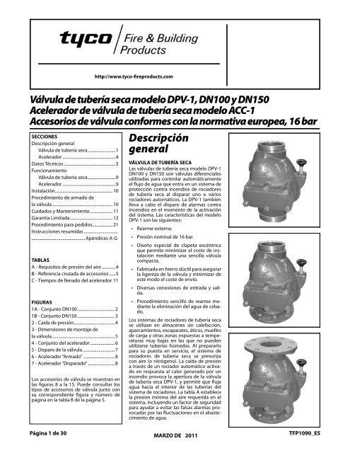
Válvula de tuberÃa seca modelo DPV-1, DN100 y DN150 Acelerador ...
Válvula de tuberÃa seca modelo DPV-1, DN100 y DN150 Acelerador ...
Válvula de tuberÃa seca modelo DPV-1, DN100 y DN150 Acelerador ...

You also want an ePaper? Increase the reach of your titles
YUMPU automatically turns print PDFs into web optimized ePapers that Google loves.
Página 1 <strong>de</strong> 30<br />
Technical Services: http://www.tyco-fireproducts.com<br />
Tel: (800) 381-9312 / Fax: (800) 791-5500<br />
Mo<strong>de</strong>l Válvula <strong>DPV</strong>-1 <strong>de</strong> tubería Dry<strong>seca</strong> Pipe mo<strong>de</strong>lo Valve, <strong>DPV</strong>-1, <strong>DN100</strong> <strong>DN100</strong> & y <strong>DN150</strong><br />
Mo<strong>de</strong>l <strong>Acelerador</strong> ACC-1 <strong>de</strong> válvula Dry Pipe <strong>de</strong> tubería Valve <strong>seca</strong> Accelerator<br />
mo<strong>de</strong>lo ACC-1<br />
European Accesorios <strong>de</strong> Conformity válvula conformes Valvecon Trim, la normativa 16 Bareuropea, 16 bar<br />
SECCIONES<br />
SECTIONS<br />
Descripción general<br />
Válvula <strong>de</strong> tubería <strong>seca</strong>...........................1<br />
General Description<br />
<strong>Acelerador</strong>...................................................4<br />
Dry Pipe Valve . . . . . . . . . 1<br />
Datos Técnicos.................................................5<br />
Funcionamiento<br />
Accelerator . . . . . . . . . . . 1<br />
Technical Válvula Data <strong>de</strong> tubería . . . <strong>seca</strong>...........................9<br />
. . . . . . . 5<br />
Operating<br />
<strong>Acelerador</strong>...................................................9<br />
Principles<br />
Instalación...................................................... 10<br />
Dry Pipe Valve . . . . . . . . . 9<br />
Procedimiento <strong>de</strong> armado <strong>de</strong><br />
la Accelerator válvula......................................................... . . . . . . . . . . . 910<br />
Installation Cuidados y Mantenimiento...................... . . . . . . . . . . . 1011<br />
Valve Garantía Setting Limitada........................................ Procedure . . . . 1012<br />
Procedimiento para pedidos................... 21<br />
Care and Maintenance . . . . 11<br />
Instrucciones resumidas.................................<br />
Limited .................................................. Warranty . . . . Apéndices . . . . 12 A-G<br />
Or<strong>de</strong>ring Procedure . . . . . . 21<br />
Summary Instructions . . . . . .<br />
TABLAS . . . . . . . . . Appendices A-G<br />
A - Requisitos <strong>de</strong> presión <strong>de</strong>l aire..............4<br />
TABLES B - Referencia cruzada <strong>de</strong> accesorios.......5<br />
C - Tiempos <strong>de</strong> llenado <strong>de</strong>l acelerador.11<br />
A - Air Pressure Requirements . 4<br />
B - Trim Cross Reference . . . . 6<br />
CFIGURAS<br />
- Accelerator Fill Times . . . 11<br />
1A - Conjunto <strong>DN100</strong>................................... 2<br />
FIGURES 1B - Conjunto <strong>DN150</strong>.................................... 3<br />
2 - Caída <strong>de</strong> presión....................................... 4<br />
1A - <strong>DN100</strong> Assembly . . . . . . 2<br />
3 - Dimensiones <strong>de</strong> montaje <strong>de</strong><br />
1B<br />
la válvula...........................................................<br />
- <strong>DN150</strong> Assembly . . . . . . 3<br />
5<br />
24 -- Pressure Conjunto <strong>de</strong>l Loss acelerador........................6<br />
. . . . . . . . 4<br />
35 -- Valve Disparo Take-Out <strong>de</strong> la válvula............................... Dimensions . 5 7<br />
4<br />
6<br />
-<br />
-<br />
Accelerator<br />
<strong>Acelerador</strong> “Armado”<br />
Assembly<br />
..............................<br />
. . . . 6<br />
8<br />
7 - <strong>Acelerador</strong> “Disparado” ......................... 8<br />
5 - Valve Operation . . . . . . . 7<br />
6 - Accelerator “Set” . . . . . . . 8<br />
Los accesorios <strong>de</strong> válvula se muestran en<br />
7las - Accelerator figuras 8 a la “Tripped” 15. Pue<strong>de</strong> consultar . . . . 8 los<br />
tipos <strong>de</strong> accesorios <strong>de</strong> válvula junto con<br />
su correspondiente figura y número <strong>de</strong><br />
Valve página Trim en la istabla illustrated B <strong>de</strong> la página in Figures 5.<br />
8 thru 15. Refer the Table B on<br />
Page 5 for types of trim and corresponding<br />
figure and page number.<br />
Page 1 of 22<br />
General<br />
Descripción<br />
Description<br />
general<br />
DRY VÁLVULA PIPEDE VALVE TUBERÍA SECA<br />
The Las válvulas <strong>DN100</strong> and <strong>de</strong> tubería <strong>DN150</strong>, <strong>seca</strong> Mo<strong>de</strong>l mo<strong>de</strong>lo <strong>DPV</strong>-1<br />
Dry <strong>DN100</strong> Pipey Valves <strong>DN150</strong> son are válvulas differential diferenciales valves<br />
used utilizadas to automatically para controlar control automáticamente the flow<br />
of el water flujo <strong>de</strong> into agua a que dry entra pipe fire en un protection sistema <strong>de</strong><br />
sprinkler protección systems contra incendios upon operation <strong>de</strong> rociadores of<br />
one<br />
<strong>de</strong> tubería<br />
or more<br />
<strong>seca</strong><br />
automatic<br />
al disparar<br />
sprinklers.<br />
uno o varios<br />
The<br />
rociadores automáticos. La <strong>DPV</strong>-1 también<br />
<strong>DPV</strong>-1<br />
lleva a<br />
also<br />
cabo<br />
provi<strong>de</strong>s<br />
el disparo<br />
for<br />
<strong>de</strong> alarmas<br />
actuation<br />
contra<br />
of<br />
fire<br />
incendios<br />
alarms<br />
en<br />
upon<br />
el momento<br />
system<br />
<strong>de</strong><br />
operation.<br />
la activación<br />
The <strong>de</strong>l sistema. Mo<strong>de</strong>l <strong>DPV</strong>-1 Las características features are <strong>de</strong>l as mo<strong>de</strong>lo follows:<br />
<strong>DPV</strong>-1 son las siguientes:<br />
• • External Rearme reset. externo.<br />
• • 16Presión bar pressure nominal rating. <strong>de</strong> 16 bar.<br />
• • Unique Diseño offset especial single <strong>de</strong> clapeta clapperexcéntrica<br />
<strong>de</strong>sign<br />
enabling que permite a simple minimizar compact el coste valve <strong>de</strong> to instalación<br />
installation mediante una labor. sencilla válvula<br />
minimize<br />
compacta.<br />
• Ductile iron construction to ensure a<br />
• lightweight Fabricada en valve hierro todúctil minimize para asegurar shipping<br />
la ligereza cost. <strong>de</strong> la válvula y minimizar <strong>de</strong><br />
este modo el coste <strong>de</strong> envío.<br />
• A variety of inlet and outlet connections.<br />
Diversas conexiones <strong>de</strong> entrada y sali-<br />
•<br />
• Simple da. reset procedure through the<br />
• elimination Procedimiento of priming sencillo water. <strong>de</strong> rearme mediante<br />
la eliminación <strong>de</strong>l agua <strong>de</strong> cebado.<br />
sprinkler systems are used in<br />
Dry pipe<br />
unheated warehouses, parking garages,<br />
Los sistemas <strong>de</strong> rociadores <strong>de</strong> tubería <strong>seca</strong><br />
se utilizan<br />
store<br />
en<br />
windows,<br />
almacenes<br />
attic<br />
sin calefacción,<br />
spaces,<br />
loading aparcamientos, docks, escaparates, and otheráticos, areas muelles exposed<br />
<strong>de</strong> carga to freezing y otras zonas temperatures, expuestas a where temperaturas<br />
filled muy bajas pipe en cannot las que beno utilized. pue<strong>de</strong>n<br />
water<br />
When utilizarse settuberías for service, húmedas. theAl dry prepararlo pipe<br />
sprinkler para su puesta systemen is pressurized servicio, el sistema with air <strong>de</strong><br />
(or rociadores nitrogen). <strong>de</strong> tubería The loss <strong>seca</strong> ofse pressure presuriza<br />
through con aire an (o nitrógeno). operated automatic La caída <strong>de</strong> sprinkler<br />
a través in response <strong>de</strong> un rociador to heat automático from aactiva-<br />
fire<br />
presión<br />
permits do en respuesta the <strong>DPV</strong>-1 al calor Dry generado Pipe Valve por toun<br />
open incendio andprovoca allow a la flow apertura of water <strong>de</strong> into la válvula the<br />
sprinkler<br />
<strong>de</strong> tubería<br />
system<br />
<strong>seca</strong> <strong>DPV</strong>-1,<br />
piping.<br />
y permite<br />
Table<br />
que<br />
A establishes<br />
fluja<br />
agua hacia el interior <strong>de</strong> las tuberías <strong>de</strong>l<br />
sistema <strong>de</strong><br />
the<br />
rociadores.<br />
minimum<br />
La tabla<br />
required<br />
A establece<br />
system<br />
la presión air pressure mínima that <strong>de</strong>l inclu<strong>de</strong>s aire requerida a safety en el<br />
factor sistema, to incluyendo help prevent un factor false operations<br />
<strong>de</strong> seguridad<br />
that para occur ayudar due a evitar to water las falsas supply alarmas fluctuationsvocadas<br />
por las fluctuaciones en el abaste-<br />
pro-<br />
ACCELERATOR<br />
cimiento <strong>de</strong> agua.<br />
The optional Mo<strong>de</strong>l ACC-1 Accelerator<br />
DRAFT 10/13/05<br />
TFP1090_ES<br />
TFP1090
Página Page 2 <strong>de</strong> of30<br />
22<br />
TFP1090_ES<br />
10<br />
6<br />
7<br />
8<br />
9<br />
2<br />
CONJUNTO CLAPPER<br />
DE CLAPETA<br />
ASSEMBLY<br />
11<br />
12<br />
13<br />
14<br />
15, 18<br />
16<br />
17<br />
PARTES RESET DEL<br />
PLUNGER PISTÓN DE<br />
REARME PARTS<br />
1<br />
4<br />
3<br />
5<br />
N.º Descripción Cant. Ref.<br />
1NO.<br />
Cuerpo DESCRIPTION<br />
<strong>de</strong> la válvula............. QTY. REF. 1 NS<br />
21Asiento Valve <strong>de</strong> Body agua y aire.......... 1 NR 1 NS<br />
3<br />
2<br />
Tapa<br />
Air<br />
<strong>de</strong>l<br />
and<br />
agujero<br />
Water<br />
<strong>de</strong> inspección.............................................<br />
1 NS<br />
Junta Seat <strong>de</strong> la ............<br />
tapa <strong>de</strong>l agujero 1 NR<br />
4 1 (b)<br />
3<strong>de</strong> inspección..........................<br />
Handhole Cover<br />
1 See (a)<br />
54Tornillo Handhole <strong>de</strong> cabeza Cover hexagonal<br />
1/2-13 UNC x 1”....................... 6 TS<br />
Gasket .......... 1 See (d)<br />
6 Clapeta....................................... 1 (a)<br />
5 1/2-13 UNC x 1"<br />
7 Revestimiento <strong>de</strong> la clapeta 1 (a) o (b)<br />
8 Placa<br />
Hex<br />
<strong>de</strong> retención<br />
Head Cap<br />
<strong>de</strong>l revestimiento<br />
Screw<strong>de</strong> ...........<br />
la clapeta.......... 6 CH 1 (a)<br />
96Tornillo Clapper <strong>de</strong> cabeza .......... hexagonal 1 See (c)<br />
7hueca Clapper 1/4-20 Facing UNC x 1/2”..... 1 See 7 (c) or (a)(d)<br />
10 Pasador <strong>de</strong> bisagra <strong>de</strong> la<br />
8clapeta....................................... Clapper Facing<br />
1 (a)<br />
11 Perilla Retaining <strong>de</strong> rearme.................... Plate<br />
1 See 1 (c) (c)<br />
129<br />
Muelle 1/4-20 <strong>de</strong> rearme................... UNC x 1/2"<br />
13 Casquillo Socket <strong>de</strong> Head rearme.............. Cap<br />
14 Junta Screw tórica . <strong>de</strong>l ..........<br />
casquillo <strong>de</strong> 7<br />
1<br />
1<br />
See (c)<br />
(c)<br />
(c)<br />
10rearme........................................ Clapper Hinge<br />
1 (b) o (c)<br />
15 Junta<br />
Pin<br />
tórica<br />
.............<br />
<strong>de</strong>l pistón <strong>de</strong><br />
1 See (b)<br />
rearme........................................ 1 (b) o (c)<br />
16<br />
11<br />
Pistón<br />
Reset<br />
<strong>de</strong> rearme....................<br />
Knob ...... 1 See<br />
1<br />
(e)<br />
(c)<br />
1712Subconjunto Reset Spring <strong>de</strong> enclava-<br />
Reset <strong>de</strong> rearme.................. Bushing 1 See 1 (e) (c)<br />
..... 1 See (e)<br />
13miento<br />
1814Grasa Reset <strong>de</strong> fluorosilicona Bushing Dow<br />
Corning<br />
O-Ring<br />
FS3452,<br />
...........<br />
1,5 g...........<br />
1 See<br />
1<br />
(d)<br />
(b)<br />
or<br />
o (c)<br />
(e)<br />
NS: No sustituible<br />
15 Reset Plunger<br />
TS: Tornillería simple<br />
O-Ring .......... 1 See (d) or (e)<br />
16 Reset Plunger ..... 1 See (e)<br />
17 Reset Latch<br />
Subassembly ..... 1 See (e)<br />
18 Dow Corning FS3452<br />
Flourosilicone REPUESTOS<br />
N.º Descripción Grease, 1.5 g ..... 1 See p/n (d) or (e)<br />
(a) El conjunto <strong>de</strong> clapeta NR: Not Replaceable<br />
compren<strong>de</strong> los elementos: CH: Common Hardware<br />
6 al 9........................................ 92-309-1-403<br />
(b) El juego <strong>de</strong> piezas <strong>de</strong><br />
REPLACEMENT PARTS<br />
repuesto compren<strong>de</strong> los<br />
NO. elementos: DESCRIPTION P/N<br />
(a) 4, 7, Handhole 14, 15, 18...................... Cover ...... 92-309-1-404 92-309-1-401<br />
(c) El juego <strong>de</strong> piezas <strong>de</strong>l pistón<br />
Clapper <strong>de</strong> rearme Hinge compren<strong>de</strong> Pin .... 92-309-1-402<br />
(b)<br />
(c) los Clapper elementos: Assembly<br />
11 a Inclu<strong>de</strong>s 18.................................... Items: 92-309-1-405<br />
6 through 9 .......... 92-309-1-403<br />
(d) Repair Parts Kit<br />
Inclu<strong>de</strong>s Items:<br />
4, 7, 14, 15, 18 ....... 92-309-1-404<br />
(e) Reset Plunger Parts Kit<br />
Inclu<strong>de</strong>s Items:<br />
11 through 18 ........ 92-309-1-405<br />
FIGURE 1A<br />
<strong>DN100</strong> MODEL <strong>DPV</strong>-1 DRY PIPE VALVE<br />
— ASSEMBLY —<br />
FIGURA 1A<br />
VÁLVULA DE TUBERÍA SECA MODELO <strong>DPV</strong>-1 <strong>DN100</strong><br />
— ENSAMBLAJE —
TFP1090_ES Page Página 3 3 of <strong>de</strong> 22 30<br />
NO.<br />
N.º Descripción<br />
DESCRIPTION QTY. REF.<br />
Cant. Ref.<br />
1 Cuerpo <strong>de</strong> la válvula............... 1 NS<br />
1 Valve Body ....... 1 NR<br />
2 Asiento <strong>de</strong> aire y agua............ 1 NS<br />
2 Air and Water<br />
3 Junta tórica <strong>de</strong>l cierre <strong>de</strong><br />
agua.............................................. Seat 1 NR1 NS<br />
34 Junta Water tórica Seal <strong>de</strong>l cierre <strong>de</strong> aire 1 NS<br />
O-Ring .......... 1 NR<br />
4 Air Seal O-Ring .... 1 NR<br />
NO.<br />
N.º Descripción<br />
DESCRIPTION QTY.<br />
Cant.<br />
REF.<br />
Ref.<br />
NO. N.º Descripción DESCRIPTION QTY. REF. Cant. Ref.<br />
5 Tornillo <strong>de</strong> cabeza hexagonal<br />
hueca 3/6-16 UNC x 1”... 8 NS<br />
5/8-11 UNC x 1”......................... 6 TS<br />
8 Tornillo <strong>de</strong> cabeza hexagonal<br />
5 3/8-16 UNC x 1"<br />
8 5/8-11 UNC x 1"<br />
6 Tapa<br />
Socket<br />
<strong>de</strong>l agujero<br />
Head Cap<br />
<strong>de</strong> inspección..............................................<br />
Screw . 8 NR1 (a)<br />
Screw ........... 6 CH<br />
Hex Head Cap<br />
9 Clapeta......................................... 1 (a)<br />
67 Junta Handhole <strong>de</strong> la tapa Cover <strong>de</strong>l agujero<br />
10 Revestimiento <strong>de</strong> la clapeta 1 (a) o(b)<br />
... 1 See (a)<br />
9 Clapper .......... 1 See (c)<br />
7 <strong>de</strong> Handhole inspección........................... Cover<br />
1 (d)<br />
11 Placa <strong>de</strong> retención <strong>de</strong>l revestimiento<br />
Clapper <strong>de</strong> Facing la clapeta............ 1 See 1 (c) or (a) (d)<br />
10<br />
Gasket .......... 1 See (d)<br />
11 12 Tornillo Clapper <strong>de</strong> Facing cabeza hexagonal<br />
9 (a)<br />
hueca Retaining 1/4-20 Plate UNC x .... 1/2”....... 1 See (c)<br />
Pasador <strong>de</strong> bisagra <strong>de</strong> la<br />
12 13 1/4-20 UNC x 1/2"<br />
1 (a)<br />
clapeta.........................................<br />
14 Perilla Socket <strong>de</strong> Head rearme...................... Cap<br />
1 (c)<br />
15 Muelle Screw <strong>de</strong> . rearme..................... 9 See 1 (c) (c)<br />
13 16 Casquillo Clapper<strong>de</strong> Hinge rearme................ 1<br />
14<br />
17 Junta Pin tórica .............<br />
<strong>de</strong>l casquillo 1<strong>de</strong><br />
See (b)<br />
(c)<br />
14 rearme.......................................... Reset Knob<br />
1 See 1 (e)(b) o (c)<br />
9<br />
15 18 Junta Reset tórica Spring <strong>de</strong>l pistón ..... <strong>de</strong> 1 See (e)<br />
15<br />
rearme.......................................... 1 (b) o (c)<br />
16<br />
19 Pistón<br />
Reset<br />
<strong>de</strong><br />
Bushing<br />
rearme......................<br />
.... 1 See<br />
1<br />
(e)<br />
(c)<br />
17 Reset Bushing<br />
10<br />
20 Subconjunto <strong>de</strong> enclavamiento<br />
O-Ring <strong>de</strong> rearme.................... 1 See 1 (d) or (c) (e)<br />
CONJUNTO CLAPPER<br />
16<br />
DE ASSEMBLY CLAPETA<br />
18 21 Grasa Reset <strong>de</strong> Plunger fluorosilicona Dow<br />
11<br />
RESET Corning<br />
O-Ring<br />
FS3452,<br />
...........<br />
1,5 g.............<br />
1 See<br />
1<br />
(d)<br />
(b)<br />
or<br />
o<br />
(e)<br />
(c)<br />
PARTES DEL<br />
17 PLUNGER 19 Reset Plunger ..... 1<br />
NS:<br />
See<br />
No<br />
(e)<br />
sustituible<br />
PISTÓN DE<br />
PARTS<br />
TS: Tornillería simple<br />
REARME 20 Reset Latch<br />
12<br />
Subassembly ..... 1 See (e)<br />
18, 21<br />
21 Dow Corning FS3452<br />
Flourosilicone<br />
19<br />
Grease, 1.5 g ..... 1 See (d) or (e)<br />
REPUESTOS NR: Not Replaceable<br />
CH: Common Hardware<br />
20<br />
N.º Descripción<br />
p/n<br />
(a) El conjunto <strong>de</strong> clapeta<br />
compren<strong>de</strong> REPLACEMENT los elementos: PARTS<br />
NO. 9 DESCRIPTION<br />
al 13...................................... 92-309-1-603<br />
P/N<br />
(b) El juego <strong>de</strong> piezas <strong>de</strong><br />
(a) repuesto Handhole compren<strong>de</strong> Cover ...... los 92-309-1-601<br />
(b) elementos: Clapper Hinge Pin .... 92-309-1-602<br />
(c) 7, Clapper 10, 17, 18, Assembly 21..................... 92-309-1-604<br />
(c) El juego <strong>de</strong> piezas <strong>de</strong>l pistón<br />
<strong>de</strong> rearme compren<strong>de</strong><br />
Inclu<strong>de</strong>s Items:<br />
los 9 through elementos: 12 ......... 92-309-1-603<br />
(d) 11 Repair a 21..................................... Parts Kit<br />
92-309-1-405<br />
Inclu<strong>de</strong>s Items:<br />
2<br />
7, 10, 17, 18, 21 ...... 92-309-1-604<br />
(e) Reset Plunger Parts Kit<br />
Inclu<strong>de</strong>s Items:<br />
14 through 21 ........ 92-309-1-405<br />
4<br />
1<br />
7<br />
6<br />
3<br />
5<br />
13<br />
8<br />
FIGURE FIGURA 1B 1B<br />
VÁLVULA <strong>DN150</strong> DE MODEL TUBERÍA <strong>DPV</strong>-1 SECA MODELO DRY PIPE<strong>DPV</strong>-1 VALVE<strong>DN150</strong><br />
— ENSAMBLAJE ASSEMBLY —
Página Page 4 <strong>de</strong> of30<br />
22<br />
TFP1090_ES<br />
Presión Maximum máxima<br />
<strong>de</strong>l Supply abas-<br />
Water<br />
System Intervalo Air <strong>de</strong><br />
presión Pressure<strong>de</strong>l<br />
tecimiento Pressure, <strong>de</strong>l Range, aire <strong>de</strong>l<br />
bar agua sistema bar<br />
(bar)<br />
1,4<br />
(bar)<br />
0,7<br />
1,4 0,7<br />
4,1<br />
4,1<br />
1,0 - 1,6<br />
1,0 - 1,6<br />
5,5<br />
5,5<br />
1,4 - 1,9<br />
1,4 - 1,9<br />
6,9<br />
6,9<br />
1,7 - 2,3<br />
1,7 - 2,3<br />
8,3<br />
8,3<br />
2,1 - 2,6<br />
2,1 - 2,6<br />
10,0<br />
10,0<br />
2,4 - 3,0<br />
2,4 - 3,0<br />
11,4<br />
11,4<br />
2,8 - 3,3<br />
2,8 - 3,3<br />
12,8<br />
12,8<br />
3,1 - 3,7<br />
3,1 - 3,7<br />
14,1<br />
14,1<br />
3,4 - 4,0<br />
3,4 - 4,0<br />
15,5<br />
15,5<br />
3,8 - 4,3<br />
3,8 - 4,3<br />
16,0<br />
16,0<br />
4,1 - 4,6<br />
4,1 - 4,6<br />
TABLE A<br />
SYSTEMTABLA AIR PRESSURE<br />
A<br />
PRESIÓN REQUIREMENTS<br />
DEL AIRE DEL SISTEMA<br />
REQUISITOS<br />
CAÍDA DE PRESIÓN NOMINAL EN bar<br />
NOMINAL PRESSURE DROP IN BAR<br />
0,60<br />
0,50<br />
0,40<br />
0,30<br />
0,20<br />
0,10<br />
0,09<br />
0,08<br />
0,07<br />
0,06<br />
0,05<br />
0,04<br />
<strong>DN100</strong><br />
<strong>DN150</strong><br />
is a quick opening <strong>de</strong>vice that is inten<strong>de</strong>d<br />
to reduce the time for valve<br />
ACELERADOR<br />
El<br />
operation<br />
acelerador<br />
following<br />
opcional<br />
the<br />
mo<strong>de</strong>lo<br />
operation<br />
ACC-1<br />
of<br />
es<br />
un<br />
one<br />
dispositivo<br />
or more automatic<br />
<strong>de</strong> apertura<br />
sprinklers.<br />
rápida concebido<br />
para reducir el tiempo <strong>de</strong> activación<br />
The<br />
<strong>de</strong><br />
Mo<strong>de</strong>l<br />
la válvula<br />
ACC-1<br />
tras<br />
Accelerator<br />
el disparo <strong>de</strong><br />
automatically<br />
uno o varios<br />
rociadores<br />
adjusts<br />
automáticos.<br />
to both small<br />
El<br />
and<br />
acelerador<br />
slow<br />
mo<strong>de</strong>lo changes ACC-1 in system se ajusta pressure, automáticamente but trips<br />
a when cambios there pequeños is a rapid y lentos and steady <strong>de</strong> la presión drop<br />
<strong>de</strong>l in pressure sistema, pero (asgenera in the un case disparo of a cuando sprinkler<br />
produce operation). una caída Upon rápida tripping, y sostenida the Ac-<br />
<strong>de</strong><br />
se<br />
la celerator presión (tal transmits y como suce<strong>de</strong> systemtras air la activaciósure<strong>de</strong><br />
toun the rociador). intermediate Cuando chamber es disparado, of<br />
pres-<br />
el theacelerador Mo<strong>de</strong>l <strong>DPV</strong>-1 transmite Dry Pipe la presión Valve. <strong>de</strong>l This aire<br />
<strong>de</strong>l neutralizes sistema a the la cámara differential intermedia pressure <strong>de</strong> la<br />
válvula holding<strong>de</strong> the tubería Mo<strong>de</strong>l <strong>seca</strong> <strong>DPV</strong>-1 mo<strong>de</strong>lo Dry <strong>DPV</strong>-1. Pipe De<br />
este Valve modo closed neutraliza and permits la presión it to open. diferencial<br />
que mantiene cerrada la válvula <strong>de</strong> tubería<br />
The Mo<strong>de</strong>l <strong>seca</strong> mo<strong>de</strong>lo ACC-1 <strong>DPV</strong>-1, Accelerator y se provoca has su a<br />
apertura. unique, positive action, internal antiflood<br />
<strong>de</strong>vice and a ball float which<br />
El combine acelerador to mo<strong>de</strong>lo preventACC-1 water dispone and water <strong>de</strong> un<br />
dispositivo borne <strong>de</strong>bris interno from especial entering anti-inundación the more<br />
<strong>de</strong> sensitive acción positiva operating y un areas flotador of <strong>de</strong> thebola accelerator.<br />
que<br />
se combinan<br />
The anti-flood<br />
para evitar<br />
<strong>de</strong>vice<br />
la entrada<br />
seals<br />
<strong>de</strong><br />
and<br />
agua<br />
y<br />
latches<br />
<strong>de</strong> los residuos<br />
immediately<br />
transportados<br />
upon operation<br />
por ésta<br />
of<br />
en<br />
las zonas operativas más sensibles <strong>de</strong>l acelerador.<br />
the Mo<strong>de</strong>l<br />
Este<br />
ACC-1<br />
dispositivo<br />
Accelerator<br />
anti-inundación<br />
without<br />
se<br />
cierra<br />
waiting<br />
y enclava<br />
for a pressure<br />
inmediatamente<br />
build-up<br />
al disparar<br />
in the<br />
el intermediate acelerador mo<strong>de</strong>lo chamber ACC-1 of the sin dry esperar pipea<br />
una valve. acumulación The latching <strong>de</strong> presión featureen keeps la cámara the<br />
intermedia anti-flood <strong>de</strong> <strong>de</strong>vice la válvula sealed, <strong>de</strong> tubería even<strong>seca</strong>. while La<br />
característica the system is <strong>de</strong> being enclavamiento drained. The mantiene ball<br />
cerrado float seals el dispositivo the pilot chamber anti-inundación, inlet port incluso<br />
if there mientras is an inadvertent se drena el sistema. trip of the El flotador<br />
pipe<strong>de</strong> valve, bola cierra due for la toma example, <strong>de</strong> entrada to an<strong>de</strong> airla<br />
cámara compressor <strong>de</strong> control failure en el combined caso <strong>de</strong> que with se pro-<br />
a<br />
dry<br />
duzca slow loss un disparo in system acci<strong>de</strong>ntal air pressure <strong>de</strong> la válvula due to <strong>de</strong><br />
tubería a leak. <strong>seca</strong> <strong>de</strong>bido, por ejemplo, a un fallo<br />
<strong>de</strong>l compresor <strong>de</strong> aire combinado con una<br />
0,03<br />
0,02<br />
1000<br />
2000 3000 5000 7000 10000<br />
FLOW CAUDAL RATE EN INLITROS LITRESPOR PERMINUTO MINUTE (LPM) (l/min)<br />
FIGURE FIGURA 2<br />
VÁLVULAS <strong>DN100</strong>DE andTUBERÍA <strong>DN150</strong> SECA MODEL MODELO <strong>DPV</strong>-1 <strong>DPV</strong>-1 DRY PIPE <strong>DN100</strong> VALVE Y <strong>DN150</strong><br />
— NOMINAL — PÉRDIDA PRESSURE DE CARGA LOSSY VERSUS CAUDAL — FLOW —<br />
caída lenta <strong>de</strong> la WARNING<br />
presión <strong>de</strong>l aire <strong>de</strong>l sistema<br />
<strong>de</strong>bida<br />
The Mo<strong>de</strong>l<br />
a una<br />
<strong>DPV</strong>-1<br />
fuga.<br />
Dry Pipe Valves and<br />
Mo<strong>de</strong>l ACC-1 Advertencia<br />
Dry Pipe Valve Acceleratorinstalarse<br />
<strong>de</strong>scribed y realizarse herein el must mantenimen-<br />
be in-<br />
Deberá<br />
to stalled <strong>de</strong> la válvula and maintained <strong>de</strong> tubería <strong>seca</strong> in compliance<br />
mo<strong>de</strong>lo <strong>DPV</strong>-<br />
1 with y <strong>de</strong>l this acelerador document <strong>de</strong> válvula in addition <strong>de</strong> tubería to <strong>seca</strong> the<br />
mo<strong>de</strong>lo standards ACC-1 recognized aquí <strong>de</strong>scritos bycumpliendo the Approval con<br />
lo agency, estipulado inen addition este documento, anyasí other como<br />
con authorities las normas having reconocidas jurisdiction. por la agencia Failure <strong>de</strong><br />
homologación to do so may y por impair cualquier the otra performance<br />
of these El incumplimiento <strong>de</strong>vices. <strong>de</strong> este re-<br />
autoridad<br />
jurisdiccional.<br />
quisito pue<strong>de</strong> perjudicar el funcionamiento<br />
The <strong>de</strong> los owner dispositivos.<br />
responsible for maintaining<br />
their fire protection system and <strong>de</strong>vices<br />
propietario in proper es responsable operating <strong>de</strong> mantener condition. su<br />
El<br />
sistema The installing <strong>de</strong> protección contractor incendios or manufacturer<br />
should en estado be contacted <strong>de</strong> funcionamiento. with any<br />
y sus<br />
dispositivos<br />
En questions.<br />
caso <strong>de</strong> duda, ponerse en contacto con el<br />
instalador o fabricante.
TFP1090_ES Page Página 5 5 of <strong>de</strong> 22 30<br />
Datos Technical técnicos<br />
Homologaciones Data<br />
Las válvulas <strong>de</strong> tubería <strong>seca</strong> mo<strong>de</strong>lo <strong>DPV</strong>-1<br />
<strong>DN100</strong> Approvals: y <strong>DN150</strong>, con o sin acelerador <strong>de</strong> válvula<br />
The<strong>de</strong> <strong>DN100</strong> tubería and <strong>seca</strong> <strong>DN150</strong> mo<strong>de</strong>lo Mo<strong>de</strong>l ACC-1, <strong>DPV</strong>-1 poseen<br />
las Dry homologaciones Pipe Valves with FM, or LPCB, without VDS y Mo<strong>de</strong>l CE con<br />
accesorios ACC-1 Dry <strong>de</strong> Pipe válvula Valve conformes Accelerator con la are normativa<br />
FM, LPCB, europea VDS, (véanse and las CE figuras Approved 8 a 15).<br />
with European Conformity Valve Trim<br />
Válvula <strong>de</strong> tubería <strong>seca</strong>:<br />
(Ref. Figures 8 thru 15).<br />
Las válvulas <strong>de</strong> tubería <strong>seca</strong> mo<strong>de</strong>lo <strong>DPV</strong>-1<br />
<strong>DN100</strong><br />
Dry Pipe<br />
y <strong>DN150</strong><br />
Valve:<br />
están diseñadas para instalaciones<br />
verticales (flujo ascen<strong>de</strong>nte) y<br />
una<br />
The<br />
presión<br />
<strong>DN100</strong><br />
nominal<br />
and <strong>DN150</strong>,<br />
máxima<br />
Mo<strong>de</strong>l<br />
<strong>de</strong> servicio<br />
<strong>DPV</strong>-1<br />
<strong>de</strong><br />
16<br />
Dry<br />
bar.<br />
Pipe<br />
La relación<br />
Valves<br />
entre<br />
are for<br />
la caída<br />
vertical<br />
<strong>de</strong> presión<br />
installations<br />
y (flow el flujo going se muestra up), and en la they figura are2,<br />
y rated las dimensiones for use at<strong>de</strong> amontaje maximum <strong>de</strong> la service válvula<br />
nominal<br />
aparecen pressureen ofla 16 figura bar. 3. The nominal pressure<br />
loss versus flow is shown in Figureconexiones<br />
2, and thecon valve bridas take-out están perforadas dimen-<br />
Las<br />
<strong>de</strong> sions acuerdo are con shown la norma in Figure ISO 2084 3. (PN10/16)<br />
o ANSI B16.1 (Clase 125). Las conexiones <strong>de</strong><br />
salida Flanged ranuradas, connections según corresponda, are drilled per presentan<br />
ISO 2084 incisiones (PN10/16) correspondientes ANSI B16.1 a las<br />
especificaciones (Class 125). The estándar grooved <strong>de</strong> outlet ranuras connections,<br />
tuberías as <strong>de</strong> applicable, acero. Estas are incisiones cut ac-<br />
son<br />
<strong>de</strong><br />
las<br />
a<strong>de</strong>cuadas cordance para with su standard uso con groove acoplamientos specifications<br />
extemos for ranurados steel pipe. <strong>de</strong> tuberías Theyhomo-<br />
are<br />
<strong>de</strong><br />
logados suitablepara for use la utilización with grooved en sistemas end pipe <strong>de</strong><br />
protección couplingscontra that are incendios. listed or approved<br />
Las for fire conexiones protection roscadas systemestán service. fabricadas<br />
<strong>de</strong> Threa<strong>de</strong>d acuerdo con port la norma connections ISO 7/1, are con el per fin<br />
<strong>de</strong> ISOaceptar 7/1 tofácilmente readily accept el conjunto the trim <strong>de</strong> accesoriorangement<br />
<strong>de</strong>tallado <strong>de</strong>tailed en las in figuras Figures 8 a la 815.<br />
-15.<br />
ar-<br />
Los Components componentes of the <strong>de</strong> la <strong>DN100</strong> válvula <strong>DPV</strong>-1 <strong>DPV</strong>-1<br />
<strong>DN100</strong> Valve se aremuestran shown en in la Figure figura 1A, 1A, and y los<br />
componentes<br />
components<br />
<strong>de</strong><br />
of<br />
la<br />
the<br />
válvula<br />
<strong>DN150</strong><br />
<strong>DPV</strong>-1<br />
<strong>DPV</strong>-1<br />
<strong>DN150</strong><br />
se muestran en la figura 1B. El cuerpo <strong>de</strong> la<br />
válvula<br />
Valve<br />
y<br />
are<br />
la tapa<br />
shown<br />
<strong>de</strong>l agujero<br />
in Figure<br />
<strong>de</strong> inspección<br />
1B. The<br />
están<br />
Body<br />
hechos<br />
and Handhole<br />
<strong>de</strong> hierro<br />
Cover<br />
dúctil.<br />
are<br />
La junta<br />
ductile<br />
<strong>de</strong><br />
la iron. tapa The <strong>de</strong>l agujero Handhole <strong>de</strong> inspección Cover Gasket está hecha<br />
neoprene, <strong>de</strong> neopreno, and the y el Clapper revestimiento Facing <strong>de</strong> isla<br />
clapeta EPDM. es The <strong>de</strong> EPDM. Air/Water El anillo Seat <strong>de</strong>l asiento Ring is <strong>de</strong><br />
is<br />
aire/agua brass, theestá Clapper hecho is <strong>de</strong> copper, bronce, and la clapeta both<br />
es the<strong>de</strong> Clapper cobre y Retaining tanto la placa Plate<strong>de</strong> and retención Latch<br />
como are bronze. el enclavamiento The Hinge<strong>de</strong> Pin la clapeta is aluminum son <strong>de</strong><br />
bronce. bronze, El pasador and the <strong>de</strong> bisagra fasteners está hecho for the <strong>de</strong><br />
bronce Handhole <strong>de</strong> aluminio, Cover are y los carbon cierres steel. <strong>de</strong> la tapa<br />
<strong>de</strong>l agujero <strong>de</strong> inspección son <strong>de</strong> acero <strong>de</strong><br />
carbono. Valve Trim:<br />
The Valve Trim is illustrated in Figures<br />
Accesorios<br />
8 and 15<br />
<strong>de</strong><br />
(Ref.<br />
válvula:<br />
Table B). The Valve<br />
Los Trimaccesorios forms a<strong>de</strong> part válvula of the se muestran laboratory en<br />
las approval figuras 8 of y 15 the (véase <strong>DPV</strong>-1 la tabla Valve B). Los and accesorios<br />
is<br />
necessary<br />
<strong>de</strong> válvula<br />
for the<br />
forman<br />
proper<br />
parte<br />
operation<br />
<strong>de</strong> la homologación<br />
en laboratorio <strong>de</strong> la válvula <strong>DPV</strong>-1<br />
of<br />
y<br />
the<br />
son<br />
<strong>DPV</strong>-1<br />
necesarios<br />
Valve.<br />
para<br />
Each<br />
el<br />
package<br />
funcionamiento<br />
of trim<br />
correcto<br />
inclu<strong>de</strong>s<br />
<strong>de</strong><br />
the<br />
dicha<br />
following<br />
válvula<br />
items:<br />
<strong>DPV</strong>-1. Cada paquete<br />
<strong>de</strong> accesorios incluye los siguientes<br />
elementos: • Water Supply Pressure Gauge<br />
• System<br />
Manómetro<br />
Air Pressure<br />
<strong>de</strong> la presión<br />
Gauge<br />
<strong>de</strong>l abastecimiento<br />
Drain <strong>de</strong>l agua Valve<br />
• Main<br />
• Low Manómetro Body Drain <strong>de</strong> la Valve presión <strong>de</strong>l aire <strong>de</strong>l<br />
• Alarm sistema Test Valve<br />
• Automatic Válvula <strong>de</strong> <strong>de</strong>sagüe Drain Valve principal<br />
• Provision<br />
Válvula <strong>de</strong><br />
For<br />
<strong>de</strong>sagüe<br />
An Optional<br />
<strong>de</strong> la parte inferior<br />
Accelerator<br />
<strong>de</strong>l cuerpo<br />
• Válvula <strong>de</strong> prueba <strong>de</strong> alarma<br />
• Válvula <strong>de</strong> <strong>de</strong>sagüe automática<br />
Diámetro Valve Size <strong>de</strong> la<br />
válvula<br />
Válvula Alarm <strong>de</strong> Test prueba Valve<br />
<strong>de</strong> alarma<br />
<strong>Acelerador</strong> Accelerator<br />
<strong>DN100</strong><br />
<strong>DN100</strong><br />
<strong>DN150</strong><br />
<strong>DN150</strong><br />
Three-Way<br />
Tres vías<br />
Standard<br />
Normal<br />
Yes<br />
Sí<br />
No<br />
No<br />
TABLA TABLEB<br />
REFERENCIA REFERENCE PARA EL FOR NÚMERO CORRESPONDING<br />
CORRESPONDIENTE<br />
DE FIGURA Y PÁGINA— FIGUREACCESORIOS NUMBER AND DE PAGE VÁLVULA NUMBER CONFORMES CON LA<br />
— EUROPEAN CONFORMITY VALVE TRIM —<br />
NORMATIVA EUROPEA —<br />
FIGURE FIGURA 33<br />
VÁLVULAS <strong>DN100</strong> and DE TUBERÍA <strong>DN150</strong> MODEL SECA MODELO <strong>DPV</strong>-1 DRY <strong>DPV</strong>-1 PIPE <strong>DN100</strong> VALVE Y <strong>DN150</strong><br />
— DIMENSIONES TAKE-OUT DIMENSIONS DE MONTAJE — —<br />
• Provisión <strong>de</strong> un acelerador opcional<br />
Air Supply:<br />
Alimentación Table A shows <strong>de</strong> the aire: system air pressure<br />
La requirements tabla A muestra as alos function requisitos of the <strong>de</strong> presión water<br />
<strong>de</strong>l supply aire <strong>de</strong>l pressure. sistema en The función air (or <strong>de</strong> nitrogen) la presión<br />
<strong>de</strong>l pressure abastecimiento in the sprinkler <strong>de</strong> agua. system Se recomiendommen<strong>de</strong>d<br />
mantener automáticamente be automatically la presión main-<br />
is rec-<br />
<strong>de</strong>l tained aire by (o <strong>de</strong>l using nitrógeno) one of <strong>de</strong>l the sistema following <strong>de</strong><br />
rociadores pressure maintenance utilizando, <strong>de</strong> entre <strong>de</strong>vices, los siguientepropriate:<br />
dispositivos <strong>de</strong> mantenimiento <strong>de</strong> la<br />
as ap-<br />
presión, el que resulte a<strong>de</strong>cuado:<br />
• Mo<strong>de</strong>l Dispositivo AMD-1 <strong>de</strong> Air mantenimiento Maintenance<strong>de</strong> Device<br />
presión (pressure <strong>de</strong>l aire reducing mo<strong>de</strong>lo type). AMD-1 (tipo<br />
la<br />
• Mo<strong>de</strong>l reductor AMD-2 <strong>de</strong> presión). Air Maintenance Device<br />
Dispositivo (compressor <strong>de</strong> mantenimiento control type). <strong>de</strong> la<br />
•<br />
• Mo<strong>de</strong>l presión <strong>de</strong>l AMD-3 aire mo<strong>de</strong>lo Nitrogen AMD-2 Maintenance<br />
control Device mediante (high compresor). pressure reduc-<br />
(tipo <strong>de</strong><br />
ing type).<br />
• Dispositivo <strong>de</strong> mantenimiento <strong>de</strong> la<br />
presión <strong>de</strong>l nitrógeno mo<strong>de</strong>lo AMD-3<br />
(tipo reductor <strong>de</strong> alta presión).<br />
Dispositivo <strong>de</strong> apertura rápida:<br />
Figura<br />
Figure<br />
número Number<br />
Página<br />
Page<br />
número Number<br />
8 13<br />
× × × 8 13<br />
9 14<br />
× × × 9 14<br />
10 15<br />
× × × 10 15<br />
11 16<br />
× × × 11 16<br />
12 17<br />
× × × 12 17<br />
13 18<br />
× × × 13 18<br />
14 19<br />
× × × 14 19<br />
15 20<br />
× × × 15 20<br />
346 mm<br />
FxF, (BxB, FxG, BxR<br />
or o RxR) GxG<br />
<strong>DN100</strong><br />
<strong>DN150</strong><br />
406 mm<br />
FxF, (BxB, FxG, BxR<br />
or o GxG RxR)<br />
De manera opcional, la válvula <strong>de</strong> tubería<br />
<strong>seca</strong> Quick mo<strong>de</strong>lo Opening <strong>DPV</strong>-1 Device: pue<strong>de</strong> ser adquirida<br />
junto As an con option, el acelerador the Mo<strong>de</strong>l mecánico <strong>DPV</strong>-1 <strong>de</strong> Dry válvula<br />
Pipe<strong>de</strong> Valve tubería may <strong>seca</strong> be ACC-1 acquired (véase with la figura the<br />
4). Mo<strong>de</strong>l El ACC-1 ACC-1 se utiliza Mechanical para reducir Dry el tiempo Pipe<br />
que Valve pasa Accelerator hasta disparo (Ref. <strong>de</strong> Figure la válvula, 4) The tras<br />
el ACC-1 disparo is<strong>de</strong> used uno o tovarios reduce rociadores the time automáticos.<br />
valve actuation following the operation<br />
of one or more automatic sprinklers.<br />
Patentes:<br />
Patentes Patents: U.S.A. n.º 6.557.645<br />
U.S.A. Patent No. 6,557,645 and<br />
4,570,719.
Página <strong>de</strong> 30<br />
Page 6 of 22<br />
TFP1090_ES<br />
TFP1090<br />
NO.<br />
No.<br />
DESCRIPTION<br />
DESCRIPCIÓN<br />
QTY.<br />
CANT..P/N<br />
P/N<br />
1 Base 1 NS<br />
Base 1 NR<br />
2 Cover Tapa 1 1 NS NR<br />
3 Upper Placa <strong>de</strong>l Diaphragm diafragma superior 1 (c)<br />
4 Plate Conjunto <strong>de</strong> placa <strong>de</strong> pivote 1 1 (b) See (c)<br />
4 Pivot Plate<br />
a Pasador espiral 1<br />
Assembly 1 See (b)<br />
ab Spirol Placa <strong>de</strong> Pinpivote 1 1<br />
5b Pivot PistónPlate 1 1 (a)<br />
5 Plunger Tornillo mecánico <strong>de</strong> cabeza 1 See (a)<br />
a Pan Hd. Machine<br />
1<br />
plana<br />
Screw Anillo retenedor <strong>de</strong>l diafragma<br />
superior<br />
1<br />
b<br />
Upper Diaphragm<br />
2<br />
c Retaining Diafragma Ring superior 2 1<br />
c Upper Diaphragm 1<br />
d Contratuerca 1<br />
d Jam Nut 1<br />
6 Exhaust Válvula <strong>de</strong> Valve escape 1 1 (a) See (a)<br />
a Upper Tapón Plug superior 1 1<br />
b Washer Aran<strong>de</strong>la 1 1<br />
c Lower Diaphragm 1<br />
c Diafragma inferior 1<br />
d Lower Plug 1<br />
ed O-Ring* Tapón inferior 1 1<br />
fe O-Ring Junta tórica* Retainer 1 1<br />
gf Exhaust Retenedor Valve <strong>de</strong> la Screw junta tórica 1 1<br />
7 Rd.<br />
Tornillo<br />
Head<br />
<strong>de</strong><br />
Machine<br />
la válvula <strong>de</strong><br />
g Screw,<br />
1<br />
escape<br />
7 1/4"-20 Tornillo UNC mecánico x 5/8" <strong>de</strong> cabeza 6 See (c)<br />
8 Cover<br />
redonda,<br />
Gasket<br />
1/4”-20 UNC x<br />
1<br />
5/8” 6 (c)<br />
See (a)<br />
9 Vent Plug 1 See (c)<br />
8 Junta <strong>de</strong> la tapa 1 (a)<br />
10 O-Ring* 1 See (a)<br />
11 9 Restriction Tapón <strong>de</strong> venteo 1 1 (c) See (a)<br />
12 10 Restriction Junta tórica* Access<br />
1 (a)<br />
11 Plug Restricción 1 1 (a) See (c)<br />
13 Pan Tapón Hd. <strong>de</strong> Machine restricción <strong>de</strong><br />
12 Screw,<br />
1 (c)<br />
acceso<br />
13 No. Tornillo 10-32 mecánico UNF x 5/8" nº 10-32 4 See (b)<br />
14 Cotter UNF x Pin 5/8” 1 4 (b) See (b)<br />
15<br />
14<br />
Lever<br />
Pasador <strong>de</strong> chaveta<br />
1<br />
1 (b)<br />
See (b)<br />
16 Retaining Ring 1 See (b)<br />
17 15 Anti-Flood Palanca Valve 1 1 (b) See (b)<br />
18 16 Relief Anillo Valve retenedor 1 1 (b) See (b)<br />
19 17 Spring Válvula anti-inundación1 1 (b) See (b)<br />
20 Relief Valve Seat 1 See (b)<br />
18 Válvula <strong>de</strong> seguridad 1 (b)<br />
21 O-Ring* 1 See (b)<br />
22 19 Seal Muelle Washer 1 1 (b) See (b)<br />
23 Latch Asiento <strong>de</strong> la válvula <strong>de</strong><br />
20<br />
1 1 (b) See (a)<br />
24 Fillerster seguridadHd.<br />
21 Machine Junta tórica* Screw,<br />
1 (b)<br />
22 1/4"-20 Aran<strong>de</strong>la UNC <strong>de</strong> cierre x 1-1/2" 8 1 (b) See (c)<br />
25 Plug Seat 1 See (c)<br />
23 Enclavamiento 1 (a)<br />
26 O-Ring* 1 See (c)<br />
27<br />
24<br />
O-Ring*<br />
Tornillo mecánico <strong>de</strong> cabeza<br />
1 See (a)<br />
28 Reset<br />
Fillister,<br />
Knob<br />
1/4”-20 UNC x 1-1/2”<br />
1<br />
8 (c)<br />
See (c)<br />
29 25 Anti-Flood Asiento <strong>de</strong>l Seat tapón 1 (c)<br />
26 Assembly Junta tórica* 1 (c)<br />
27 w/Ball Junta tórica* Float 1 1 (a) See (b)<br />
a Insert 1<br />
28 Perilla <strong>de</strong> rearme 1 (c)<br />
b Seal 1<br />
c Gui<strong>de</strong><br />
Conjunto <strong>de</strong> asiento antiinundación<br />
con flotador<br />
29<br />
1<br />
d Ball 1 1 (b)<br />
e Clip <strong>de</strong> bola<br />
1<br />
af O-Ring* Injerto 1 1<br />
b Cierre 1<br />
* Requires c Guía thin film of<br />
1<br />
FS3452 Fluorosilicone Grease<br />
d Bola 1<br />
(a) e<br />
f<br />
Repair Abraza<strong>de</strong>ra Parts Kit (a)<br />
Inclu<strong>de</strong>s Junta tórica* Items 5, 6, 8,<br />
1<br />
1<br />
* Requiere 10, 11, una 23, capa 27 & <strong>de</strong>lgada <strong>de</strong> grasa <strong>de</strong> fluorosilicona<br />
1.5 FS3452 grams of FS3452 92-311-1-116<br />
(a) Juego <strong>de</strong> piezas <strong>de</strong> repuesto<br />
(b) Replacement (a) Compren<strong>de</strong> Parts los artículos<br />
Kit 5, 6, (b) 8, Inclu<strong>de</strong>s 10, 11, 23, Items 27 y 1,5 g <strong>de</strong><br />
4,<br />
FS3452<br />
13-22, 29 &<br />
92-311-1-116<br />
1.5 grams of FS3452 92-311-1-117<br />
(b) Juego <strong>de</strong> piezas <strong>de</strong> repuesto<br />
(b) Compren<strong>de</strong> los artículos 4,<br />
(c) Replacement Parts<br />
13-22, 29 y 1,5 g <strong>de</strong> FS3452 92-311-1-117<br />
Kit (c) Inclu<strong>de</strong>s Items<br />
(c)<br />
3,<br />
Juego<br />
7, 9,<br />
<strong>de</strong><br />
12,<br />
piezas<br />
24-26,<br />
<strong>de</strong><br />
28,<br />
repuesto<br />
&<br />
(c)<br />
1.5<br />
Compren<strong>de</strong><br />
grams of FS3452<br />
los artículos<br />
92-311-1-118<br />
3, 7, 9, 12, 24-26, 28 y 1,5 g <strong>de</strong><br />
NR: Not FS3452 Replaceable<br />
92-311-1-118<br />
NS: No sustituible<br />
(TAPÓN DE RESTRICCIÓN<br />
DE ACCESO)<br />
FIGURA 4<br />
CONJUNTO DEL ACELERADOR FIGURE 4 MODELO ACC-1<br />
MODEL ACC-1 ACCELERATOR ASSEMBLY<br />
(TAPÓN DE VENTEO)<br />
(PERILLA DE REARME)
TFP1090_ES Página 7 <strong>de</strong> 30<br />
TFP1090<br />
Page 7 of 22<br />
PRESIÓN AIR PRESSURE DE AIRE DE EN-<br />
TRADA TO SYSTEM AL SISTEMA<br />
WATERFLOW<br />
FLUJO TO SYSTEM AL SISTEMA<br />
CONJUNTO<br />
CLAPPER<br />
DE<br />
CLAPETA ASSEMBLY TOTAL-<br />
MENTE FULLY ABIERTO OPEN<br />
TOMA DE<br />
ALIMEN- DN25<br />
AIR TACIÓN SUPPLY DE<br />
AIRE PORT DN25<br />
CONJUNTO<br />
CLAPPER<br />
DE ASSEMBLY CLAPETA<br />
EN POSICIÓN IN SET<br />
POSITION ARMADA<br />
01<br />
PRESIÓN DN15DEL<br />
ABASTECI- WATER<br />
MIENTO<br />
SUPPLY<br />
DE<br />
AGUA Y TOMA<br />
PRESSURE<br />
DE PRUEBA<br />
DE & ALARMA<br />
TEST DN15 PORT<br />
02<br />
CONJUNTO CLAPPER<br />
ASSEMBLY<br />
DE CLAPETA<br />
ENCLA-<br />
LATCHED<br />
VADO EN<br />
POSICIÓN OPEN<br />
ABIERTA<br />
04<br />
DN20 DN20 TOMA<br />
DE LOW DESAGÜE BODY<br />
INFERIOR DRAIN<br />
DEL PORT CUERPO<br />
DN20<br />
DEL FROM ABASTECI-<br />
WATER MIENTO SUPPLY DE AGUA<br />
FIGURE FIGURA 5A 5A<br />
POSICIÓN SET POSITION ARMADA<br />
DRAIN DESAGÜE FROM DE LA<br />
INSTALACIÓN<br />
SYSTEM<br />
CIERRE WATER DE SUPPLY SUMI-<br />
NISTRO SHUT DE OFF AGUA<br />
EL ENCLAVAMIENTO<br />
DE CLAPPER CLAPETA LATCH PIVOTA<br />
PIVOTS PARA TO PERMITIR ALLOWLA<br />
APERTURA COMPLE-<br />
CLAPPER ASSEMBLY<br />
TA DEL CONJUNTO<br />
TO FULLY DE OPEN CLAPETA<br />
TOMA DE ALAR-<br />
DN20<br />
MA ABIERTA<br />
ALARM<br />
PORT A LA OPEN ATMÓS- TO<br />
ATMOSPHERE<br />
FERA DN20<br />
03<br />
CONJUNTO CLAPPER<br />
ASSEMBLY<br />
DE CLAPETA<br />
ASIENTO AIR<br />
DE SEAT AIRE<br />
ASIENTO WATER<br />
DE SEAT AGUA<br />
03<br />
TOMA ALARMDE<br />
ALARMA PORT<br />
PASO VALVE DE AGUA<br />
CÁMARA<br />
INTERMEDIATE<br />
WATERWAY<br />
PRINCIPAL<br />
INTERMEDIA<br />
CHAMBER<br />
FIGURE FIGURA 5B<br />
SET POSICIÓN POSITION<br />
INTERMEDIATE<br />
DE ARMADO<br />
DE<br />
CHAMBER<br />
CÁMARA<br />
INTERMEDIA<br />
CONJUNTO RESET<br />
ASSEMBLY<br />
DE REARME<br />
EL CLAPPER ENCLAVA-<br />
MIENTO LATCHDE<br />
ENCLAVA-<br />
CLAPPER<br />
PIVOTS LA CLAPETA TO<br />
MIENTO DE<br />
PIVOTA PARA<br />
LATCH<br />
UNLATCH<br />
LA CLAPETA DESENCLAVAR<br />
EL CLAPPER CONJUNTO<br />
ASSEMBLY DE CLAPETA<br />
TOMA DN50 DE DES-<br />
05 AGÜE MAINPRIN-<br />
DRAIN<br />
CIPAL PORT DN50<br />
DEL FROM ABASTECI-<br />
WATER MIENTO SUPPLY DE AGUA<br />
FIGURE<br />
FIGURA 5C<br />
5C<br />
OPERATED POSICIÓN ACTIVADA POSITION<br />
DRAIN FROM<br />
SYSTEM<br />
DRENAJE<br />
COMPLETE<br />
DE LA INSTA-<br />
LACIÓN COMPLETADO<br />
WATER CIERRE DE SUPPLY SUMI-<br />
NISTRO SHUTDE OFF AGUA<br />
TOMA DE<br />
AGUA ALARM PARA PORT<br />
ALARMA WATERFLOW<br />
TO ALARM<br />
PULSE<br />
PUSH<br />
AQUÍ<br />
HERE<br />
PARA<br />
REARMAR TO RESETLA<br />
VÁLVULA VALVE<br />
RESET<br />
PERI-<br />
KNOB<br />
LLA DE<br />
REARME<br />
CONJUNTO CLAPPER<br />
ASSEMBLY<br />
DE CLAPETA<br />
CON RESEATED ASIENTO<br />
REINSTALADO<br />
FIGURE 5D<br />
FIGURA 5D<br />
POSICIÓN<br />
DRAIN<br />
DE<br />
POSITION<br />
DRENAJE<br />
FIGURE 5E<br />
FIGURA 5E<br />
RESET POSITION<br />
POSICIÓN DE REARME<br />
FIGURE FIGURA 5<br />
VÁLVULA MODEL TUBERÍA <strong>DPV</strong>-1 DRY SECA PIPE MODELO VALVE <strong>DPV</strong>-1 (<strong>DN100</strong> (MOSTRADA SHOWN) <strong>DN100</strong>)<br />
— POSICIONES — SET ANDDE OPEN ARMADO POSITIONS Y APERTURA — —
Página <strong>de</strong> 30<br />
Page 8 of 22<br />
TFP1090_ES<br />
TFP1090<br />
CONEXIÓN DEL MANÓ-<br />
METRO NPT DE 1/4”<br />
CÁMARA DI-<br />
FERENCIAL<br />
RESTRICCIÓN<br />
CÁMARA DE CONTROL<br />
MUELLE<br />
VÁLVULA ANTI-INUNDACIÓN<br />
FLOTADOR DE BOLA<br />
ENTRADA NPT DE 1/2”<br />
TOMA DE ENTRADA DE LA<br />
CÁMARA DE CONTROL<br />
VÁLVULA DE SEGURIDAD<br />
VÁLVULA DE ESCAPE<br />
CÁMARA DE ENTRADA<br />
SALIDA NPT DE 1/2<br />
CÁMARA DE SALIDA<br />
FIGURE 6<br />
FIGURA 6<br />
MODEL ACC-1 ACCELERATOR IN SET POSITION<br />
ACELERADOR MODELO ACC‐1 EN POSICIÓN DE ARMADO<br />
PISTÓN<br />
ENCLAVAMIENTO<br />
PALANCA<br />
PERILLA DE REARME<br />
DE LAS TUBERÍAS<br />
DEL SISTEMA<br />
TOMA DE PURGA<br />
HACIA LA CÁMARA<br />
INTERMEDIA DE LA VÁL-<br />
VULA DE TUBERÍA SECA<br />
FIGURA FIGURE7<br />
7<br />
ACELERADOR MODEL ACC-1 MODELO ACCELERATOR ACC‐1 EN POSICIÓN IN TRIPPED DE DISPARO POSITION
TFP1090_ES Página 9 <strong>de</strong> 30<br />
Funcionamiento<br />
VÁLVULA DE TUBERÍA SECA<br />
La válvula <strong>de</strong> tubería <strong>seca</strong> mo<strong>de</strong>lo <strong>DPV</strong>-1<br />
es una válvula <strong>de</strong> tipo diferencial que utiliza<br />
una presión <strong>de</strong>l sistema (<strong>de</strong> aire o nitrógeno)<br />
sustancialmente más baja que la<br />
presión <strong>de</strong> la alimentación (<strong>de</strong> agua), para<br />
mantener la posición armada mostrada en<br />
la figura 5A. La naturaleza diferencial <strong>de</strong> la<br />
<strong>DPV</strong>-1 se basa en la diferencia <strong>de</strong> área entre<br />
el asiento <strong>de</strong> aire y el asiento <strong>de</strong> agua,<br />
en combinación con el cociente <strong>de</strong> la diferencia<br />
radial entre el pasador <strong>de</strong> bisagra y<br />
el centro <strong>de</strong>l asiento <strong>de</strong> agua por un lado, y<br />
el pasador <strong>de</strong> bisagra y el centro <strong>de</strong>l asiento<br />
<strong>de</strong> aire por otro. Esta diferencia es tal que<br />
la <strong>DPV</strong>-1 presenta un cociente nominal <strong>de</strong><br />
disparo <strong>de</strong> 5,5:1 (presión <strong>de</strong>l agua - presión<br />
<strong>de</strong>l aire).<br />
La tabla A establece la presión mínima <strong>de</strong>l<br />
aire requerida en el sistema, incluyendo un<br />
factor <strong>de</strong> seguridad para ayudar a evitar las<br />
falsas alarmas provocadas por las fluctuaciones<br />
en el abastecimiento <strong>de</strong> agua.<br />
La cámara intermedia <strong>de</strong> la <strong>DPV</strong>-1 está formada<br />
por la zona situada entre el asiento<br />
<strong>de</strong> aire y el asiento <strong>de</strong> agua, tal y como se<br />
muestra en la figura 5B. La cámara intermedia<br />
permanece normalmente a presión<br />
atmosférica a lo largo <strong>de</strong> la conexión <strong>de</strong> la<br />
toma <strong>de</strong> alarma y los accesorios <strong>de</strong> válvula,<br />
hasta la válvula <strong>de</strong> <strong>de</strong>sagüe automática<br />
normalmente abierta (véanse las figuras 8<br />
a la 15). El hecho <strong>de</strong> que la cámara intermedia<br />
(véase la figura 5B) esté abierta a la<br />
atmósfera resulta fundamental para mantener<br />
armada la válvula <strong>DPV</strong>-1, ya que, en<br />
caso contrario, no podrá alcanzarse sobre el<br />
conjunto <strong>de</strong> clapeta la presión total resultante<br />
<strong>de</strong> la presión <strong>de</strong>l aire <strong>de</strong>l sistema. Por<br />
ejemplo, si la presión <strong>de</strong>l aire <strong>de</strong>l sistema es<br />
<strong>de</strong> 1,7 bar y hay una presión <strong>de</strong> 1,0 bar encerrada<br />
en la cámara intermedia, la presión<br />
resultante a lo largo <strong>de</strong> la parte superior <strong>de</strong><br />
la clapeta será sólo <strong>de</strong> 0,7 bar. Esta presión<br />
sería insuficiente para mantener el conjunto<br />
<strong>de</strong> clapeta cerrado frente a una presión<br />
<strong>de</strong>l abastecimiento <strong>de</strong> agua <strong>de</strong> 6,9 bar.<br />
Cuando uno o varios rociadores automáticos<br />
son activados en respuesta a un incendio,<br />
la presión <strong>de</strong>l aire existente <strong>de</strong>ntro <strong>de</strong><br />
las tuberías <strong>de</strong>l sistema se pier<strong>de</strong> a través<br />
<strong>de</strong> los rociadores abiertos. Una vez reducida<br />
suficientemente la presión <strong>de</strong>l aire, la<br />
presión <strong>de</strong>l agua supera el diferencial que<br />
mantiene cerrado el conjunto <strong>de</strong> clapeta, y<br />
dicho conjunto <strong>de</strong> clapeta oscila perdiendo<br />
el contacto con el asiento <strong>de</strong> agua, tal y<br />
como se muestra en la figura 5C. Esta acción<br />
permite que el agua fluya hacia el interior<br />
<strong>de</strong> las tuberías <strong>de</strong>l sistema y que sea posteriormente<br />
<strong>de</strong>scargada <strong>de</strong>s<strong>de</strong> los rociadores<br />
abiertos. Asimismo, una vez está abierto el<br />
conjunto <strong>de</strong> clapeta, la cámara intermedia<br />
se presuriza y el agua fluye a través <strong>de</strong> la<br />
toma <strong>de</strong> alarma (véase la figura 5B) situada<br />
en la parte posterior <strong>de</strong> la válvula <strong>DPV</strong>-1.<br />
Conforme el flujo que atraviesa la toma <strong>de</strong><br />
alarma supera la capacidad <strong>de</strong> drenaje <strong>de</strong> la<br />
válvula <strong>de</strong> <strong>de</strong>sagüe automática, la tubería<br />
<strong>de</strong> alarma es presurizada para disparar las<br />
alarmas <strong>de</strong> flujo <strong>de</strong> agua <strong>de</strong>l sistema.<br />
Tras el disparo <strong>de</strong> una válvula y el posterior<br />
cierre <strong>de</strong> la válvula <strong>de</strong> control principal <strong>de</strong>l<br />
sistema para <strong>de</strong>tener el flujo <strong>de</strong> agua, el<br />
conjunto <strong>de</strong> clapeta se enclava en posición<br />
abierta, tal y como se muestra en la figura<br />
5D. El enclavamiento en posición abierta<br />
<strong>de</strong> la <strong>DPV</strong>-1 permite el drenaje completo<br />
<strong>de</strong>l sistema (incluyendo cualquier cascarilla<br />
<strong>de</strong> óxido suelta) a través <strong>de</strong> la toma <strong>de</strong> <strong>de</strong>sagüe<br />
principal.<br />
Durante el procedimiento <strong>de</strong> rearme <strong>de</strong> la<br />
válvula, y una vez se ha drenado por completo<br />
el sistema, pue<strong>de</strong> pulsarse fácilmente<br />
la perilla externa <strong>de</strong> rearme para <strong>de</strong>senclavar<br />
externamente el conjunto <strong>de</strong> clapeta, tal<br />
y como se muestra en la figura 5E. De esta<br />
manera, se <strong>de</strong>vuelve el conjunto <strong>de</strong> clapeta<br />
a su posición normal armada, para facilitar<br />
el armado <strong>de</strong>l sistema <strong>de</strong> rociadores <strong>de</strong> tubería<br />
<strong>seca</strong> sin necesidad <strong>de</strong> retirar la tapa<br />
<strong>de</strong>l agujero <strong>de</strong> inspección.<br />
ACELERADOR<br />
La cámara <strong>de</strong> entrada <strong>de</strong>l acelerador (véase<br />
la figura 6) se presuriza a través <strong>de</strong> su conexión<br />
con el sistema. La cámara <strong>de</strong> control,<br />
a su vez, es presurizada a través <strong>de</strong> su<br />
toma <strong>de</strong> entrada, que se forma mediante la<br />
abertura anular situada en torno al extremo<br />
inferior <strong>de</strong> la válvula anti-inundación. Conforme<br />
aumenta la presión en la cámara <strong>de</strong><br />
control, la cámara diferencial se presuriza a<br />
través <strong>de</strong> la restricción.<br />
El acelerador se encuentra en su posición<br />
armada mientras es presurizado, y también<br />
una vez se han igualado las presiones en la<br />
entrada, cámara <strong>de</strong> control y cámara diferencial.<br />
Una vez en la posición armada, la<br />
válvula <strong>de</strong> escape cierra la cámara <strong>de</strong> salida,<br />
y se mantiene fija contra su asiento mediante<br />
una combinación <strong>de</strong> empuje hacia arriba<br />
<strong>de</strong>l muelle contra la palanca y la fuerza<br />
<strong>de</strong>scen<strong>de</strong>nte neta ejercida por la presión<br />
existente en la cámara <strong>de</strong> control.<br />
Los cambios pequeños y los lentos <strong>de</strong> la<br />
presión <strong>de</strong>l sistema se compensan mediante<br />
el flujo a través <strong>de</strong> la restricción. Sin embargo,<br />
cuando se produce una caída rápida<br />
y sostenida en la presión <strong>de</strong>l sistema (es <strong>de</strong>cir,<br />
en la entrada y la cámara <strong>de</strong> control), la<br />
presión en la cámara diferencial se reduce<br />
a un ritmo sustancialmente menor. Dicho<br />
estado crea una fuerza <strong>de</strong>scen<strong>de</strong>nte neta<br />
sobre el pistón, que hace girar la palanca.<br />
Conforme gira la palanca (véase la figura<br />
7), la válvula <strong>de</strong> seguridad se eleva y pier<strong>de</strong><br />
el contacto con la toma <strong>de</strong> <strong>de</strong>scarga, y<br />
la válvula anti-inundación es empujada hacia<br />
abajo en dirección a la toma <strong>de</strong> entrada<br />
<strong>de</strong> la cámara <strong>de</strong> control, lo que hace que se<br />
ventee dicha cámara <strong>de</strong> control.<br />
La presión <strong>de</strong>l sistema en la cámara <strong>de</strong> entrada<br />
empuja y levanta la válvula <strong>de</strong> escape<br />
<strong>de</strong> su asiento. Esto hace que prosiga el giro<br />
<strong>de</strong> la palanca, hasta la posición <strong>de</strong> disparo<br />
(enclavada) (véase la figura 7). Conforme la<br />
válvula <strong>de</strong> escape se levanta <strong>de</strong> su asiento,<br />
la presión <strong>de</strong>l sistema se transfiere a la cámara<br />
intermedia <strong>de</strong> la válvula <strong>de</strong> tubería<br />
<strong>seca</strong>, lo que neutraliza el diferencial <strong>de</strong> presión<br />
que mantiene la válvula cerrada.<br />
La válvula anti-inundación cierra la toma <strong>de</strong><br />
entrada, e impi<strong>de</strong> <strong>de</strong> este modo la entrada a<br />
la cámara <strong>de</strong> control <strong>de</strong> agua y <strong>de</strong> residuos<br />
portados por ésta, como el fango.<br />
Una vez disparadas la válvula <strong>de</strong>l acelerador<br />
y la válvula <strong>de</strong> tubería <strong>seca</strong> y una vez<br />
drenado el sistema <strong>de</strong> rociadores, <strong>de</strong>ben<br />
drenarse asimismo las tuberías que van<br />
<strong>de</strong>l sistema al acelerador, y <strong>de</strong>be rearmarse/inspeccionarse<br />
el acelerador <strong>de</strong> acuerdo<br />
con las instrucciones proporcionadas en<br />
la sección Procedimiento <strong>de</strong> armado <strong>de</strong> la<br />
válvula.<br />
El caudal que atraviesa la restriccion se<br />
establece <strong>de</strong> manera tal que el acelerador<br />
mo<strong>de</strong>lo ACC-1 proporciona la máxima sensibilidad<br />
práctica a una caída <strong>de</strong> la presión<br />
<strong>de</strong>l sistema <strong>de</strong>bida al disparo <strong>de</strong> un rociador,<br />
aun siendo capaz <strong>de</strong> compensar automáticamente<br />
las variaciones normales <strong>de</strong> la<br />
presión <strong>de</strong>l sistema, como las provocadas<br />
por cambios en la temperatura ambiente.<br />
Se proporciona en la sección Procedimiento<br />
<strong>de</strong> armado <strong>de</strong> la válvula una prueba para<br />
verificar que el caudal que atraviesa la restricción<br />
se encuentra <strong>de</strong>ntro <strong>de</strong>l intervalo<br />
<strong>de</strong> comportamiento óptimo <strong>de</strong>l acelerador.
Página 10 <strong>de</strong> 30<br />
TFP1090_ES<br />
Instalación<br />
NOTAS<br />
El funcionamiento correcto <strong>de</strong> la válvula <strong>de</strong><br />
tubería <strong>seca</strong> mo<strong>de</strong>lo <strong>DPV</strong>-1 <strong>de</strong>pen<strong>de</strong> <strong>de</strong> que<br />
estén instalados correctamente sus accesorios,<br />
<strong>de</strong> acuerdo con las figuras 8 a la 15,<br />
según corresponda. La alteración <strong>de</strong> estos<br />
accesorios pue<strong>de</strong> afectar negativamente al<br />
funcionamiento <strong>de</strong> la válvula <strong>DPV</strong>-1, así como<br />
invalidar las homologaciones y las garantías<br />
<strong>de</strong>l fabricante.<br />
Si no fuera posible enclavar en posición abierta<br />
el conjunto <strong>de</strong> clapeta antes <strong>de</strong> una prueba<br />
hidrostática, dicho conjunto <strong>de</strong> clapeta podría<br />
resultar dañado.<br />
La válvula <strong>DPV</strong>-1 se <strong>de</strong>be instalar en un lugar<br />
<strong>de</strong> fácil acceso y visibilidad.<br />
La válvula <strong>DPV</strong>-1 y los accesorios asociados<br />
<strong>de</strong>ben mantenerse a una temperatura mínima<br />
<strong>de</strong> 4°C.<br />
No se permite la calorifugación <strong>de</strong> la válvula<br />
<strong>DPV</strong>-1 o <strong>de</strong> sus accesorios asociados. La calorifugación<br />
pue<strong>de</strong> provocar la formación <strong>de</strong><br />
<strong>de</strong>pósitos minerales endurecidos capaces <strong>de</strong><br />
interferir con el correcto funcionamiento <strong>de</strong><br />
la válvula.<br />
La válvula <strong>de</strong> tubería <strong>seca</strong> mo<strong>de</strong>lo <strong>DPV</strong>-1<br />
<strong>de</strong>be instalarse <strong>de</strong> acuerdo con los siguientes<br />
criterios:<br />
Paso 1. Al ensamblar válvulas sobre el terreno<br />
(es <strong>de</strong>cir, aparte <strong>de</strong> las válvulas con<br />
los accesorios ensamblados en fábrica),<br />
todos los manguitos <strong>de</strong> unión, accesorios y<br />
dispositivos <strong>de</strong>ben estar limpios y no presentar<br />
cascarillas <strong>de</strong> óxido ni rebabas antes<br />
<strong>de</strong> la instalación. Aplique sellante <strong>de</strong> roscas<br />
sólo en las rocas macho <strong>de</strong> las tuberías.<br />
Paso 2. La válvula <strong>DPV</strong>-1 <strong>de</strong>be ser ensamblada<br />
<strong>de</strong> acuerdo con las figuras 8 a la 15.<br />
Paso 3. Deberá comprobarse cuidadosamente<br />
que las válvulas <strong>de</strong> retención, filtros,<br />
válvulas globo, etc., están instaladas con las<br />
flechas <strong>de</strong> flujo en el sentido correcto.<br />
Paso 4. Deberá establecerse una disposición<br />
a<strong>de</strong>cuada para la eliminación <strong>de</strong>l agua<br />
drenada. El agua drenada <strong>de</strong>be dirigirse<br />
<strong>de</strong> manera tal que no provoque daños acci<strong>de</strong>ntales<br />
a la propiedad o lesiones a las<br />
personas.<br />
Paso 5. Se recomienda la instalación <strong>de</strong> un<br />
dispositivo <strong>de</strong> mantenimiento <strong>de</strong> aire, tal y<br />
como se <strong>de</strong>scribe en la sección Información<br />
técnica.<br />
Paso 6. Debe proporcionarse una conexión<br />
<strong>de</strong> prueba <strong>de</strong> inspector en las tuberías <strong>de</strong>l<br />
sistema en el emplazamiento más alejado<br />
<strong>de</strong> la válvula mo<strong>de</strong>lo <strong>DPV</strong>-1.<br />
Paso 7. Las conexiones eléctricas y <strong>de</strong> conductos<br />
portacables <strong>de</strong>berán realizarse <strong>de</strong><br />
acuerdo con los requisitos <strong>de</strong> la autoridad<br />
jurisdiccional.<br />
Paso 8. Antes <strong>de</strong> realizar una prueba hidrostática<br />
<strong>de</strong>l sistema <strong>de</strong> acuerdo con las<br />
normas reconocidas por la agencia homologadora,<br />
así como por cualquier otra autoridad<br />
jurisdiccional, el conjunto <strong>de</strong> clapeta<br />
<strong>de</strong>berá ser enclavado manualmente en posición<br />
abierta (véase la figura 4D); la válvula<br />
<strong>de</strong> <strong>de</strong>sagüe automática (véanse las figuras<br />
8 a la 15) <strong>de</strong>berá estar taponada temporalmente,<br />
y los tornillos <strong>de</strong> la tapa <strong>de</strong>l agujero<br />
<strong>de</strong> inspección <strong>de</strong>berán haber sido apretados<br />
siguiendo una secuencia en cruz.<br />
Procedimiento<br />
<strong>de</strong> armado <strong>de</strong> la<br />
válvula<br />
Deberán completarse los pasos 1 al 12 al armar<br />
inicialmente la válvula <strong>de</strong> tubería <strong>seca</strong><br />
<strong>DPV</strong>-1, tras una prueba operativa <strong>de</strong>l sistema<br />
<strong>de</strong> protección contra incendios o tras el<br />
disparo <strong>de</strong>l sistema <strong>de</strong>bido a un incendio.<br />
Determine cuál <strong>de</strong> las figuras 8 a la 15 aplica<br />
a su disposición <strong>de</strong> tubo ascen<strong>de</strong>nte , y proceda<br />
<strong>de</strong> la manera siguiente:<br />
Paso 1. Cierre la válvula <strong>de</strong> control principal<br />
y la válvula <strong>de</strong> control <strong>de</strong> la alimentación <strong>de</strong><br />
aire. Si la <strong>DPV</strong>-1 viene equipada con un acelerador<br />
<strong>de</strong> válvula <strong>de</strong> tubería <strong>seca</strong>, cierre la<br />
válvula <strong>de</strong> control <strong>de</strong>l acelerador.<br />
Paso 2. Abra la válvula <strong>de</strong> <strong>de</strong>sagüe principal<br />
y todos los <strong>de</strong>sagües auxiliares <strong>de</strong>l sistema.<br />
Cierre las válvulas <strong>de</strong> <strong>de</strong>sagüe auxiliares<br />
una vez cese la <strong>de</strong>scarga <strong>de</strong> agua. Deje<br />
abierta la válvula <strong>de</strong> <strong>de</strong>sagüe principal.<br />
Paso 3. Según corresponda, coloque la válvula<br />
<strong>de</strong> control <strong>de</strong> tres vías en la posición<br />
abierta.<br />
Paso 4. Verifique que la válvula <strong>de</strong> <strong>de</strong>sagüe<br />
automática ha <strong>de</strong>jado <strong>de</strong> drenar agua para<br />
<strong>de</strong>terminar que la válvula <strong>DPV</strong>-1 está completamente<br />
purgada.<br />
Paso 5. Según sea necesario, sustituya todos<br />
los rociadores que se hayan disparado.<br />
Los rociadores sustitutos <strong>de</strong>ben ser <strong>de</strong>l mismo<br />
tipo y temperatura nominal que aquellos<br />
que se han disparado.<br />
NOTA<br />
A fin <strong>de</strong> eliminar la posibilidad <strong>de</strong> un accionamiento<br />
posterior <strong>de</strong> un rociador <strong>de</strong> soldadura<br />
sobrecalentado, todos los rociadores <strong>de</strong><br />
soldadura que hayan podido estar expuestos<br />
a una temperatura superior a su temperatura<br />
ambiente nominal <strong>de</strong>ben ser sustituidos.<br />
Paso 6. Presione la perilla <strong>de</strong> rearme (figura<br />
5E) para permitir el rearme <strong>de</strong>l conjunto <strong>de</strong><br />
clapeta.<br />
Paso 7. Presurice el sistema con aire (o nitrógeno)<br />
a 0,7 bar, y a continuación abra<br />
todas las válvulas <strong>de</strong> <strong>de</strong>sagüe auxiliares <strong>de</strong><br />
las tuberías <strong>de</strong>l sistema para drenar toda el<br />
agua que pueda quedar en las secciones<br />
cerradas. Cierre cada válvula <strong>de</strong> <strong>de</strong>sagüe<br />
tan pronto como cese la <strong>de</strong>scarga <strong>de</strong> agua.<br />
Igualmente, abra parcialmente la válvula<br />
<strong>de</strong> <strong>de</strong>sagüe <strong>de</strong> la parte inferior <strong>de</strong>l cuerpo<br />
<strong>de</strong> los accesorios <strong>de</strong> válvula para asegurarse<br />
<strong>de</strong> que el tubo ascen<strong>de</strong>nte queda completamente<br />
drenado. Cierre la válvula <strong>de</strong><br />
<strong>de</strong>sagüe <strong>de</strong> la parte inferior <strong>de</strong>l cuerpo tan<br />
pronto como cese la <strong>de</strong>scarga <strong>de</strong> agua.<br />
Paso 8. Consulte la tabla A para restablecer<br />
la presión normal <strong>de</strong>l aire en el sistema<br />
necesaria para mantener cerrada la válvula<br />
<strong>DPV</strong>-1.<br />
Paso 9. Verifique que la válvula <strong>de</strong> <strong>de</strong>sagüe<br />
automática no <strong>de</strong>scarga aire.<br />
Ello indicará que se ha creado un asiento <strong>de</strong><br />
aire a<strong>de</strong>cuado <strong>de</strong>ntro <strong>de</strong> la válvula <strong>DPV</strong>-1.<br />
En el caso <strong>de</strong> que exista una <strong>de</strong>scarga <strong>de</strong><br />
aire, consulte la sección Cuidados y mantenimiento<br />
relativa a la inspección <strong>de</strong> la válvula<br />
<strong>de</strong> <strong>de</strong>sagüe automática para <strong>de</strong>terminar/corregir<br />
la causa <strong>de</strong> la fuga.<br />
Paso 10. Si la <strong>DPV</strong>-1 está equipada con un<br />
acelerador <strong>de</strong> válvula <strong>de</strong> tubería <strong>seca</strong>, reármelo<br />
<strong>de</strong> acuerdo con los pasos 10A al 10H.<br />
En caso contrario, proceda al paso 11.<br />
Paso 10A. Manteniendo el pistón <strong>de</strong><br />
la válvula <strong>de</strong> <strong>de</strong>sagüe automática presionado,<br />
abra la válvula <strong>de</strong> control <strong>de</strong>l<br />
acelerador un cuarto <strong>de</strong> giro y permita<br />
que se expulse el agua presente en las<br />
tuberías <strong>de</strong>l acelerador. Una vez cese la<br />
<strong>de</strong>scarga <strong>de</strong>l chorro <strong>de</strong> agua, cierre la<br />
válvula <strong>de</strong> control <strong>de</strong>l acelerador y suelte<br />
el pistón.<br />
Paso 10B. Extraiga lentamente el tapón<br />
<strong>de</strong> venteo situado en la parte <strong>de</strong>lantera<br />
<strong>de</strong> la tapa <strong>de</strong>l acelerador y purgue la<br />
presión residual <strong>de</strong>l aire presente en la<br />
cámara diferencial.<br />
Paso 10C. Desatornille (giro en sentido<br />
antihorario) la perilla <strong>de</strong> rearme moleteada<br />
situada en la parte <strong>de</strong>lantera <strong>de</strong>l<br />
acelerador, hasta que no se pueda girar<br />
más. Posiblemente se escuchará un clic,<br />
que es el sonido <strong>de</strong> la palanca encajando<br />
<strong>de</strong> nuevo en la posición armada.<br />
Atornille <strong>de</strong> nuevo la perilla <strong>de</strong> rearme<br />
aplicando un apriete manual.<br />
NOTA<br />
No apriete la perilla <strong>de</strong> rearme con una<br />
llave inglesa, ya que se podría dañar. La<br />
perilla <strong>de</strong> rearme sólo girará si presenta<br />
un par <strong>de</strong> torsión correspondiente a un<br />
apriete manual.<br />
Paso 10D. Sustituya el tapón <strong>de</strong><br />
venteo.<br />
Paso 10E. Verifique que la presión <strong>de</strong>l<br />
aire <strong>de</strong>l sistema ha vuelto a su valor normal.<br />
Paso 10F. Utilizando un cronómetro,<br />
anote el tiempo que tarda la presión <strong>de</strong><br />
la cámara diferencial <strong>de</strong>l acelerador en<br />
aumentar hasta 0,7 bar <strong>de</strong>s<strong>de</strong> que se<br />
abre la válvula <strong>de</strong> control <strong>de</strong>l acelerador.<br />
Para conseguir un comportamiento<br />
óptimo <strong>de</strong>l acelerador, dicho tiempo<br />
<strong>de</strong>berá estar <strong>de</strong>ntro <strong>de</strong>l intervalo <strong>de</strong> valores<br />
indicado en la tabla C.<br />
NOTA<br />
Si el tiempo que tarda en presurizarse la<br />
cámara diferencial hasta 0,7 bar no está<br />
<strong>de</strong>ntro <strong>de</strong> dicho intervalo <strong>de</strong> valores <strong>de</strong> la<br />
tabla C, <strong>de</strong>berá cerrar la válvula <strong>de</strong> control<br />
<strong>de</strong>l acelerador y llevar a cabo el procedimiento<br />
correctivo <strong>de</strong>scrito en la sección<br />
Cuidados y mantenimiento.
TFP1090_ES Página 11 <strong>de</strong> 30<br />
Presión<br />
( bar)<br />
Mínima<br />
(segundos)<br />
1,4 24 160<br />
1,7 18 116<br />
2,1 15 92<br />
2,8 10 60<br />
3,5 8 48<br />
4,1 6 36<br />
Paso 10G. Una vez la presión <strong>de</strong>l aire <strong>de</strong><br />
la cámara diferencial <strong>de</strong>l acelerador es<br />
igual a la presión <strong>de</strong>l sistema, el acelerador<br />
está armado y listo para su uso.<br />
Paso 10H. Cierre la válvula <strong>de</strong> control<br />
<strong>de</strong>l acelerador y abra lentamente la<br />
válvula <strong>de</strong> <strong>de</strong>sagüe <strong>de</strong> la parte inferior<br />
<strong>de</strong>l cuerpo <strong>de</strong> los accesorios, para purgar<br />
cualquier exceso <strong>de</strong> agua atrapada<br />
sobre la clapeta <strong>de</strong> la válvula <strong>de</strong> tubería<br />
<strong>seca</strong>. Vuelva a cerrar la válvula <strong>de</strong> <strong>de</strong>sagüe<br />
<strong>de</strong> la parte inferior <strong>de</strong>l cuerpo, <strong>de</strong>vuelva<br />
la presión <strong>de</strong>l sistema a su valor<br />
normal y reabra la válvula <strong>de</strong> control <strong>de</strong>l<br />
acelerador.<br />
Paso 11. Abra parcialmente la válvula <strong>de</strong><br />
control principal. Cierre lentamente la válvula<br />
<strong>de</strong> <strong>de</strong>sagüe principal tan pronto como<br />
se <strong>de</strong>scargue el agua <strong>de</strong> la conexión <strong>de</strong> <strong>de</strong>sagüe.<br />
Verifique que la válvula <strong>de</strong> <strong>de</strong>sagüe automática<br />
no <strong>de</strong>scarga agua.<br />
Ello indicará que se ha creado un asiento<br />
<strong>de</strong> agua a<strong>de</strong>cuado en la válvula <strong>DPV</strong>-1. En<br />
el caso <strong>de</strong> que exista una <strong>de</strong>scarga <strong>de</strong> agua,<br />
consulte la sección Cuidados y mantenimiento<br />
relativa a la inspección <strong>de</strong> la válvula<br />
<strong>de</strong> <strong>de</strong>sagüe automática para <strong>de</strong>terminar/<br />
corregir la causa <strong>de</strong> la fuga.<br />
Si no se produce ninguna fuga, la válvula<br />
<strong>DPV</strong>-1 estará lista para su puesta en funcionamiento,<br />
y la válvula <strong>de</strong> control principal<br />
<strong>de</strong>berá abrirse completamente.<br />
NOTA<br />
Tras armar un sistema <strong>de</strong> protección contra<br />
incendios, notifíquelo a las autorida<strong>de</strong>s correspondientes<br />
y asesore a las personas responsables<br />
<strong>de</strong>l control <strong>de</strong> alarmas propietarias<br />
y/o <strong>de</strong> la estación <strong>de</strong> alarmas.<br />
Paso 12. Una vez a la semana, tras el rearme<br />
<strong>de</strong> una válvula posterior a una prueba<br />
operativa o disparo <strong>de</strong>l sistema, la válvula<br />
<strong>de</strong> <strong>de</strong>sagüe <strong>de</strong> la parte inferior <strong>de</strong>l cuerpo<br />
(y cualquier otra válvula <strong>de</strong> <strong>de</strong>sagüe <strong>de</strong> la<br />
zona inferior) <strong>de</strong>berá ser abierta parcialmente<br />
(y posteriormente cerrada) para purgar el<br />
agua superflua. Repita este procedimiento<br />
hasta que no que<strong>de</strong> agua superflua.<br />
Máxima<br />
(segundos)<br />
TABLA C<br />
TIEMPOS DE LLENADO DE LA CÁMARA DIFERENCIAL A 0,7 bar<br />
Cuidados y<br />
mantenimiento<br />
Los siguientes procedimientos e inspecciones<br />
<strong>de</strong>ben ejecutarse tal y como se indica,<br />
así como todos los requisitos específicos <strong>de</strong><br />
las autorida<strong>de</strong>s jurisdiccionales. Los <strong>de</strong>fectos<br />
<strong>de</strong>berán corregirse inmediatamente.<br />
El propietario es responsable <strong>de</strong> la inspección,<br />
comprobación y mantenimiento <strong>de</strong> su<br />
sistema y dispositivos <strong>de</strong> protección contra<br />
incendios en conformidad con este documento,<br />
así como con las normas aplicables<br />
<strong>de</strong> las autorida<strong>de</strong>s jurisdiccionales. Ante<br />
cualquier duda, cabe consultar al instalador<br />
o al fabricante <strong>de</strong>l equipo.<br />
Se recomienda que un servicio <strong>de</strong> inspección<br />
cualificado realice la inspección, comprobación<br />
y mantenimiento <strong>de</strong> los sistemas<br />
<strong>de</strong> rociadores automáticos.<br />
NOTAS<br />
El procedimiento <strong>de</strong> prueba operativa y el <strong>de</strong><br />
prueba <strong>de</strong> alarma <strong>de</strong> flujo <strong>de</strong> agua provocarán<br />
el accionamiento <strong>de</strong> las alarmas asociadas.<br />
Por tanto, se <strong>de</strong>berá notificar previamente al<br />
propietario y al cuerpo <strong>de</strong> bomberos, estación<br />
<strong>de</strong> alarma, u otra estación <strong>de</strong> señales a la que<br />
estén conectadas las alarmas.<br />
Antes <strong>de</strong> cerrar la válvula <strong>de</strong> control principal<br />
<strong>de</strong>l sistema <strong>de</strong> protección contra incendios<br />
para realizar trabajos <strong>de</strong> mantenimiento en<br />
el sistema controlado, se <strong>de</strong>be obtener autorización<br />
<strong>de</strong> las autorida<strong>de</strong>s correspondientes<br />
para <strong>de</strong>jar fuera <strong>de</strong> servicio los sistemas<br />
<strong>de</strong> protección contra incendios afectados, y<br />
notificar a todo el personal que pueda verse<br />
afectado por ello.<br />
Procedimiento <strong>de</strong> activación anual<br />
Deberá verificarse el correcto funcionamiento<br />
<strong>de</strong> la válvula <strong>DPV</strong>-1 (es <strong>de</strong>cir, el disparo<br />
<strong>de</strong> la válvula <strong>DPV</strong>-1 en caso <strong>de</strong> incendio)<br />
al menos una vez al año, con arreglo al<br />
siguiente procedimiento:<br />
Paso 1. Si es necesario impedir que el agua<br />
fluya más allá <strong>de</strong>l puesto <strong>de</strong> control, lleve a<br />
cabo los siguientes pasos.<br />
• Cierre la válvula principal <strong>de</strong> control<br />
• Abra la válvula principal <strong>de</strong> <strong>de</strong>sagüe<br />
• Abra la válvula principal <strong>de</strong> control<br />
girando el volante una vuelta más<br />
<strong>de</strong> lo necesario para que empiece a<br />
pasar agua por la válvula principal<br />
<strong>de</strong> <strong>de</strong>sagüe.<br />
• Cierre la válvula principal <strong>de</strong> control<br />
Paso 2. Abra la conexión <strong>de</strong> prueba <strong>de</strong> inspector<br />
<strong>de</strong>l sistema.<br />
Paso 3. Verifique el funcionamiento <strong>de</strong> la<br />
válvula <strong>DPV</strong>-1, indicado por el flujo <strong>de</strong> agua<br />
hacia el sistema, así como el funcionamiento<br />
correcto <strong>de</strong> todas las alarmas <strong>de</strong> flujo <strong>de</strong><br />
agua.<br />
Paso 4. Cierre la válvula principal <strong>de</strong> control.<br />
Paso 5. Rearme la válvula <strong>DPV</strong>-1 con arreglo<br />
al procedimiento <strong>de</strong> armado <strong>de</strong> la válvula.<br />
NOTA<br />
Se recomienda inspeccionar en este momento<br />
el interior <strong>de</strong> la válvula, antes <strong>de</strong> realizar<br />
el rearme <strong>de</strong> la válvula <strong>DPV</strong>-1. Consulte los<br />
pasos 2 al 5 <strong>de</strong> la subsección Inspección <strong>de</strong>l<br />
cierre automático <strong>de</strong> la válvula <strong>de</strong> <strong>de</strong>sagüe<br />
para obtener instrucciones relativas a la inspección<br />
<strong>de</strong>l revestimiento <strong>de</strong> la clapeta.<br />
Procedimiento periódico<br />
<strong>de</strong> prueba <strong>de</strong> alarma <strong>de</strong> flujo <strong>de</strong> agua<br />
Deberá llevarse a cabo periódicamente la<br />
comprobación <strong>de</strong> las alarmas <strong>de</strong> flujo <strong>de</strong><br />
agua <strong>de</strong>l sistema basándose en los requisitos<br />
<strong>de</strong> la autoridad jurisdiccional. Para probar<br />
la alarma <strong>de</strong> flujo <strong>de</strong> agua, coloque la<br />
válvula <strong>de</strong> prueba <strong>de</strong> alarma <strong>de</strong> tres vías en<br />
la posición “Prueba” (“Test”) o abra la válvula<br />
<strong>de</strong> prueba <strong>de</strong> alarma estándar, según corresponda;<br />
esto hará que fluya agua hacia<br />
el presostato <strong>de</strong> <strong>de</strong>tección <strong>de</strong>l flujo <strong>de</strong> agua<br />
y/o hacia el motor hidráulico <strong>de</strong> alarma.<br />
Una vez completada la prueba satisfactoriamente,<br />
coloque la válvula <strong>de</strong> prueba <strong>de</strong><br />
alarma <strong>de</strong> tres vías en la posición “Abierta”<br />
(“Open”) o cierre la válvula <strong>de</strong> prueba <strong>de</strong><br />
alarma estándar, según corresponda.<br />
Inspección <strong>de</strong> la presión <strong>de</strong>l agua<br />
Deberá inspeccionarse periódicamente el<br />
manómetro <strong>de</strong> presión <strong>de</strong>l agua, basándose<br />
en los requisitos <strong>de</strong> la autoridad jurisdiccional,<br />
para asegurar que se mantiene la<br />
presión normal <strong>de</strong>l agua en el sistema.<br />
Inspección <strong>de</strong> la presión <strong>de</strong>l aire<br />
Deberá inspeccionarse periódicamente el<br />
manómetro <strong>de</strong> presión <strong>de</strong>l aire, basándose<br />
en los requisitos <strong>de</strong> la autoridad jurisdiccional,<br />
para asegurar que se mantiene la presión<br />
normal <strong>de</strong>l aire en el sistema.<br />
Inspección <strong>de</strong> la válvula <strong>de</strong> <strong>de</strong>sagüe<br />
automática<br />
Deberá inspeccionarse periódicamente la<br />
válvula <strong>de</strong> <strong>de</strong>sagüe automática, basándose<br />
en los requisitos <strong>de</strong> la autoridad jurisdiccional,<br />
empujando el pistón y comprobando<br />
que la válvula <strong>de</strong> <strong>de</strong>sagüe automática no<br />
<strong>de</strong>scarga agua y/o aire. La <strong>de</strong>scarga <strong>de</strong> agua<br />
y/o aire es una indicación <strong>de</strong> que los asientos<br />
<strong>de</strong> aire y/o <strong>de</strong> agua presentan fugas, lo<br />
que pue<strong>de</strong> provocar posteriormente una<br />
falsa alarma en el caso <strong>de</strong> que la cámara intermedia<br />
se presurice involuntariamente.<br />
En el caso <strong>de</strong> que existan fugas, ponga la<br />
válvula <strong>DPV</strong>-1 fuera <strong>de</strong> servicio (es <strong>de</strong>cir,<br />
cierre la válvula <strong>de</strong> control principal, abra<br />
la válvula <strong>de</strong> <strong>de</strong>sagüe principal, cierre la<br />
válvula <strong>de</strong> control <strong>de</strong> la alimentación <strong>de</strong>
Página 12 <strong>de</strong> 30<br />
TFP1090_ES<br />
aire, ponga fuera <strong>de</strong> servicio el acelerador<br />
<strong>de</strong> la válvula <strong>de</strong> tubería <strong>seca</strong>, según corresponda,<br />
cerrando la válvula <strong>de</strong> control <strong>de</strong>l<br />
acelerador, y abra la conexión <strong>de</strong> prueba<br />
<strong>de</strong> inspector para reducir a cero la presión<br />
<strong>de</strong>l aire <strong>de</strong>l sistema (manómetro), según lo<br />
indicado en el manómetro <strong>de</strong> presión <strong>de</strong>l<br />
aire <strong>de</strong>l sistema), y a continuación, una vez<br />
extraída la tapa <strong>de</strong>l agujero <strong>de</strong> inspección,<br />
lleve a cabo los siguientes pasos:<br />
Paso 1. Asegúrese <strong>de</strong> que el anillo <strong>de</strong>l<br />
asiento está limpio y no presenta muescas<br />
o grietas significativas.<br />
Paso 2. Extraiga el conjunto <strong>de</strong> clapeta <strong>de</strong><br />
la válvula tirando primero <strong>de</strong>l pasador <strong>de</strong><br />
bisagra.<br />
Paso 3. Desmonte el retenedor <strong>de</strong>l revestimiento<br />
<strong>de</strong> la clapeta y sepárelo <strong>de</strong> la clapeta<br />
para po<strong>de</strong>r extraer e inspeccionar el<br />
revestimiento. Asegúrese <strong>de</strong> que éste no<br />
muestra signos <strong>de</strong> compresión, daños, etc.<br />
Sustitúyalo si presenta signos <strong>de</strong> <strong>de</strong>sgaste.<br />
Paso 4. Limpie el revestimiento <strong>de</strong> la clapeta,<br />
la propia clapeta y el retenedor <strong>de</strong>l revestimiento<br />
<strong>de</strong> la clapeta, y vuelva a montar<br />
el conjunto.<br />
Paso 5. Vuelva a instalar el conjunto <strong>de</strong> clapeta<br />
con su pasador <strong>de</strong> bisagra e instale <strong>de</strong><br />
nuevo la tapa <strong>de</strong>l agujero <strong>de</strong> inspección.<br />
Procedimiento <strong>de</strong> inspección <strong>de</strong>l acelerador<br />
Se recomienda inspeccionar el acelerador<br />
periódicamente basándose en los requisitos<br />
<strong>de</strong> la autoridad jurisdiccional, para<br />
constatar el funcionamiento a<strong>de</strong>cuado <strong>de</strong>l<br />
acelerador sin necesidad <strong>de</strong> disparar la válvula<br />
<strong>de</strong> tubería <strong>seca</strong>. Este procedimiento<br />
<strong>de</strong>berá utilizarse también siempre que la<br />
inundación <strong>de</strong>l sistema pueda exponer el<br />
agua a una posibilidad <strong>de</strong> congelación.<br />
NOTA<br />
Consulte en la ficha técnica TFP1112 las pautas<br />
relativas a la resolución <strong>de</strong> problemas <strong>de</strong>l<br />
acelerador <strong>de</strong> la válvula <strong>de</strong> tubería <strong>seca</strong> mo<strong>de</strong>lo<br />
ACC-1.<br />
Paso 1. Verifique que la perilla <strong>de</strong> rearme<br />
está atornillada.<br />
Paso 2. Cierre la válvula <strong>de</strong> control principal<br />
<strong>de</strong>l sistema y abra la válvula <strong>de</strong> <strong>de</strong>sagüe<br />
principal para aliviar la presión <strong>de</strong>l abastecimiento<br />
<strong>de</strong> la válvula <strong>de</strong> tubería <strong>seca</strong>.<br />
Paso 3. Verifique que la válvula <strong>de</strong> control<br />
<strong>de</strong>l acelerador está abierta.<br />
Paso 4. Abra la conexión <strong>de</strong> prueba <strong>de</strong> inspector.<br />
Verifique que el tiempo que tarda<br />
en dispararse el acelerador es básicamente<br />
el mismo que en pruebas anteriores. Un<br />
golpe <strong>de</strong> aire momentáneo proce<strong>de</strong>nte <strong>de</strong><br />
la válvula <strong>de</strong> <strong>de</strong>sagüe automática indica<br />
que se ha disparado el acelerador.<br />
NOTA<br />
Conforme disminuye la presión <strong>de</strong>l sistema,<br />
busque signos <strong>de</strong> <strong>de</strong>scarga <strong>de</strong> agua <strong>de</strong>s<strong>de</strong> la<br />
toma <strong>de</strong> purga <strong>de</strong>l acelerador.<br />
Paso 5. Empuje el pistón <strong>de</strong> la válvula <strong>de</strong><br />
<strong>de</strong>sagüe automática. Un caudal constante<br />
<strong>de</strong> escape <strong>de</strong> aire indica que el acelerador<br />
se ha enclavado correctamente en la posición<br />
<strong>de</strong> disparo.<br />
Paso 6. Cierre la válvula <strong>de</strong> control <strong>de</strong>l acelerador<br />
y la conexión <strong>de</strong> prueba <strong>de</strong> inspector.<br />
Paso 7. Una vez el sistema haya recuperado<br />
automáticamente su presión normal<br />
<strong>de</strong>l aire, rearme el acelerador y la válvula<br />
<strong>de</strong> tubería <strong>seca</strong> <strong>de</strong> acuerdo con los pasos<br />
10 y 11 <strong>de</strong>l procedimiento <strong>de</strong> armado <strong>de</strong> la<br />
valvula.<br />
Garantía limitada<br />
Los productos fabricados por Tyco Fire &<br />
Building Products (TFBP) se garantizan, únicamente<br />
al Comprador original, durante un<br />
período <strong>de</strong> 10 años para cualquier <strong>de</strong>fecto<br />
<strong>de</strong>l material o la mano <strong>de</strong> obra, siempre que<br />
hayan sido pagados y correctamente instalados,<br />
y hayan recibido mantenimiento en<br />
condiciones normales <strong>de</strong> uso y servicio.<br />
Esta garantía caduca a los 10 años a partir<br />
<strong>de</strong> la fecha <strong>de</strong> expedición por parte <strong>de</strong><br />
TFBP. No se proporciona ninguna garantía<br />
a productos o componentes fabricados por<br />
empresas no afiliadas mediante propiedad<br />
con TFBP, ni a productos o componentes<br />
que hayan sido sometidos a un uso o instalación<br />
in<strong>de</strong>bidos, a corrosión, o que no hayan<br />
sido instalados, mantenidos, modificados<br />
o reparados <strong>de</strong> acuerdo con las normas<br />
reconocidas por la agencia homologadora,<br />
así como por las normas <strong>de</strong> cualquier otra<br />
autoridad jurisdiccional. Cualquier material<br />
que TFBP consi<strong>de</strong>re <strong>de</strong>fectuoso será reparado<br />
o sustituido, <strong>de</strong> acuerdo con la <strong>de</strong>cisión<br />
exclusiva <strong>de</strong> TFBP. TFBP no acepta, ni autoriza<br />
a ninguna persona a aceptar en su representación,<br />
ninguna otra responsabilidad en<br />
relación con la venta <strong>de</strong> sus productos o<br />
componentes <strong>de</strong> los mismos. TFBP no acepta<br />
ninguna responsabilidad por errores en<br />
el diseño <strong>de</strong> los sistemas <strong>de</strong> rociadores ni<br />
por información inexacta o incompleta que<br />
haya podido suministrar el comprador o los<br />
representantes <strong>de</strong> éste.<br />
En ningún caso será responsable TFBP, ya<br />
sea por contrato, <strong>de</strong>lito civil, responsabilidad<br />
objetiva o según cualquier otra teoría<br />
jurídica, <strong>de</strong> daños inci<strong>de</strong>ntales, indirectos,<br />
especiales o consecuentes, incluyendo sin<br />
limitación los gastos <strong>de</strong> mano <strong>de</strong> obra, in<strong>de</strong>pendientemente<br />
<strong>de</strong> si TFBP ha sido informado<br />
sobre la posibilidad <strong>de</strong> tales daños, y<br />
en ningún caso será la responsabilidad <strong>de</strong><br />
TFBP superior en valor al precio <strong>de</strong> venta<br />
original.<br />
Esta garantía sustituye cualquier otra<br />
garantía explícita o implícita, incluyendo<br />
cualquier garantía <strong>de</strong> comerciabilidad o<br />
a<strong>de</strong>cuación <strong>de</strong>l producto para un <strong>de</strong>terminado<br />
uso.<br />
Esta garantía limitada establece la solución<br />
exclusiva para reclamaciones basadas en<br />
una avería o <strong>de</strong>fecto en los productos, materiales<br />
o componentes, ya sea interpuesta<br />
dicha reclamación por contrato, <strong>de</strong>lito civil,<br />
responsabilidad objetiva o según cualquier<br />
otra teoría jurídica.<br />
Esta garantía aplica en toda medida permitida<br />
por la ley. La no vali<strong>de</strong>z, parcial o total,<br />
<strong>de</strong> cualquier parte <strong>de</strong> esta garantía no afecta<br />
al resto <strong>de</strong> la misma.
TFP1090_ES Página 13 <strong>de</strong> 30<br />
TFP1090<br />
Page 13 of 22<br />
No. Descripción Cant.<br />
No. Descripción Cant.<br />
1 025500013; Manómetro <strong>de</strong> agua; NPT <strong>de</strong> 1/4”; 21 bar (300 psi). 1<br />
20 ATDDMN; Accesorio adaptador; latón; rosca DN15 x DN15<br />
2 1610000210; Válvula esférica; latón; paso completo; BSP <strong>de</strong><br />
macho; chapado en níquel . . . . . . . . . . . . . . . . . . . . . . . . . . . . . . . . . . . . 4<br />
1/2”; PN30; kv=16.3; pr . . . . . . . . . . . . . . . . . . . . . . . . . . . . . . . . . . . . . . . 1<br />
21 ATDFCON; Accesorio adaptador; latón; rosca DN15 hembra x<br />
3 1610000270; Válvula esférica; latón; paso completo; BSP <strong>de</strong><br />
compr. 15 mm; chapado en níquel ............................. 1<br />
NO. 3/4”; DESCRIPTION PN30; kv=29,5; pr . . . . . . . . . . . . . . . . . . . . . . . . . . . . . . . . . . . . . . . 1QTY.<br />
NO. 22 ETDDMN; DESCRIPTION Accesorio adaptador; latón; rosca DN15 macho x QTY.<br />
4<br />
1<br />
1610000600;<br />
025500013; Water<br />
Válvula<br />
gauge;<br />
esférica;<br />
1/4"<br />
latón;<br />
npt;<br />
paso<br />
300<br />
completo;<br />
psi .................<br />
BSP <strong>de</strong> 2”;<br />
DN15 macho; chapado en níquel . . . . . . . . . . . . . . . . . . . . . . . . . . . . . . 1<br />
1 20 ATDDMN; Adapter fitting; brass;<br />
PN25; kv=265; ur ............................................. 1<br />
23 ETDMCON; Codo adaptador; latón; rosca DN15 macho x compr.<br />
2 1610000210; Ball valve; brass; full bore; 1/2" BSP; PN30;<br />
thread DN15 x DN15 male; nickel pl. ...................... 4<br />
5 2162156; Válvula <strong>de</strong> <strong>de</strong>sagüe automática; DN15; activ.: k=25 y<br />
15 mm; chapado en níquel .................................... 1<br />
no<br />
kv=16.3;<br />
activ.: k=5<br />
pr ..........................................<br />
. . . . . . . . . . . . . . . . . . . . . . . . . . . . . . . . . . . . . . . . . . . . . . . . 1<br />
1<br />
24<br />
21<br />
ETDMDFN;<br />
ATDFCON;<br />
Codo<br />
Adapter<br />
adaptador;<br />
fitting; brass;<br />
latón; rosca DN15 macho x DN15<br />
6<br />
3<br />
260;<br />
1610000270;<br />
Presostato<br />
Ball<br />
<strong>de</strong> alarma<br />
valve; brass;<br />
. . . . . . .<br />
full<br />
. . . .<br />
bore;<br />
. . . . . .<br />
3/4"<br />
. . . .<br />
BSP;<br />
. . . . . .<br />
PN30;<br />
. . . . . . . . . 1<br />
hembra; thread DN15 chapado fem. en x níquel compr.15 . . . . mm; . . . . . n. . . . . ......................<br />
. . . . . . . . . . . . . . . . . . . . . 4 1<br />
kv=29.5; pr .......................................... 1<br />
22 ETDDMN; Adapter elbow; brass;<br />
7 262; Presostato <strong>de</strong> baja presión ............................... 1<br />
25 ETEMEFN; Codo adaptador; latón; rosca DN20 macho x DN20<br />
4 1610000600; Ball valve; brass; full bore; 2" BSP; PN25;<br />
thread DN15 male x DN15 male; nickel pl. .................. 1<br />
8 305105; Válvula <strong>de</strong> retención con rosca <strong>de</strong> latón; DN15 macho<br />
hembra; chapado en níquel . . . . . . . . . . . . . . . . . . . . . . . . . . . . . . . . . . . 2<br />
x kv=265; DN15 hembra; ur ...........................................<br />
chapada en níquel 1 1<br />
26 23 K00128; ETDMCON; Prueba Adapter <strong>de</strong> alarma/válvula elbow; brass; <strong>de</strong> cierre; PN40; DN15; BSP; 3<br />
95<br />
406012; 2162156; Codo Automatic <strong>de</strong> 3 mm/m5 drain ................................... valve; 1/2";<br />
3<br />
vías thread ........................................................... DN15 male x compr.15 mm; nickel pl.<br />
1 1<br />
10 Válvula oper: k=25 <strong>de</strong> tubería & non <strong>seca</strong>; oper: <strong>DPV</strong>-1; k=5 .............................<br />
hierro dúctil; <strong>DN100</strong> 1 1<br />
27 24 MANIF3WAY; ETDMDFN; Adapter Colector; elbow; roscado; brass; latón chapado en níquel; DN25<br />
11<br />
6<br />
59304FO;<br />
260; Alarm<br />
Válvula<br />
pressure<br />
esférica;<br />
switch<br />
DN15;<br />
.............................<br />
paso completo; PN40; orificio<br />
1<br />
x thread DN15 DN15 . . . . . . . male . . . . . x. . DN15fem.; . . . . . . . . . . . . nickel . . . . . . pl. . . . ....................<br />
. . . . . . . . . . . . . . . . . . . 1 4<br />
7 roscado 262; Low<strong>de</strong> pressure venteo . switch .......................................... 3 1<br />
28 25 PTDN; ETEMEFN; Tapón; Adapter latón; rosca elbow; DN15 brass; macho; chapado en níquel . . . . 2<br />
128<br />
923431012; 305105; Check Manómetro valve brass <strong>de</strong> presión thread; <strong>de</strong>l aire;21 bar (300 psi)NPT<br />
29 RTDMBFN; thread DN20 Adaptador male x DN20 reductor; fem.; latón; nickel rosca pl. DN15 ..................<br />
macho x DN8 2<br />
<strong>de</strong> DN15 1/4” male ....................................................... x DN15 fem.; nickel plated<br />
1 1<br />
26 hem.; K00128; chapado Alarmen test/shut níquel ...................................... off valve; PN40; 1/2"; BSP; 3 way ..... 2 1<br />
139<br />
A130RIID2; 406012; Elbow Accesorio 3 mm maleable; x m5 ..............................<br />
té reductor; rosca BSP DN50 x 3<br />
30 27 RTDMEFN; MANIF3WAY; Adaptador Manifold; reductor; threa<strong>de</strong>d; latón; nickel rosca plated DN15 brass; macho x<br />
10 DN50 Dry pipe ........................................................ valve; <strong>DPV</strong>-1; ductile iron; 4"<br />
1 1<br />
DN20 DN25hem.; x DN15 chapado ........................................<br />
en níquel 1 1<br />
14 11 A280I2; 59304FO; Accesorio Ball valve; maleable; size 1/2"; manguito full bore; <strong>de</strong> unión PN40; macho; rosca<br />
31 28 RTEMDFN; PTDN; Plug; Reductor brass; adaptador; thread DN15 latón; male; rosca nickel DN20 plated macho .......... x 2<br />
BSP; venthole DN50; threa<strong>de</strong>d galvanizado. ...................................... 1 3<br />
29 DN15<br />
RTDMBFN;<br />
hembra;<br />
Adapter<br />
chapado<br />
reduce;<br />
en níquel<br />
brass;<br />
. . . . . . . . . . . . . . . . . . . . . . . . . . . . . 1<br />
15 12 A291E2; 923431012; Accesorio Air pressure maleable; gauge; tapón macho; rosca BSP; DN20;<br />
32 TTDDDFN; thread DN15 Té adaptador; male x DN8latón; fem.; rosca nickel DN15 pl. hembra ...................2<br />
x DN15<br />
galvanizado 300 psi; 1/4" . npt . . . . . .......................................<br />
. . . . . . . . . . . . . . . . . . . . . . . . . . . . . . . . . . . . . . . . . . 1<br />
hembra x DN15 hembra; chapado en níquel . . . . . . . . . . . . . . . . . . . 2<br />
1<br />
30 RTDMEFN; Adapter reduce; brass;<br />
16 13 AP100E4; A130RIID2; Manguito malleable <strong>de</strong> unión fitt.; reducing <strong>de</strong> tubería; tee; acero BSP inoxidable thread 2" x316;<br />
33 TTDDMDFN; Té adaptador; latón; rosca DN15 macho x DN15<br />
2" .... 1<br />
thread DN15 male x DN20 fem.; n. ........................ 1<br />
14 DN20; A280I2; longitud malleable 100 fitting; mm ...................................... nipple male; BSP thread;<br />
1<br />
macho x DN15 hembra; chapado en níquel . . . . . . . . . . . . . . . . . . . . 2<br />
31 RTEMDFN; Adapter reduce; brass;<br />
17 AP120I2; size 2"; galvanized Manguito <strong>de</strong> ....................................<br />
unión <strong>de</strong> tubería; acero; DN50; longitud<br />
34 UTFFMN; Unión adaptadora; latón; rosca DN25 x DN25 macho;<br />
1<br />
thread DN20 male x DN15 fem.; n. ........................ 1<br />
15<br />
120<br />
A291E2;<br />
mm; galvanizado<br />
malleable fitting;<br />
. . . . . .<br />
plug<br />
. . . . .<br />
male;<br />
. . . . . .<br />
BSP<br />
. . . . .<br />
thread;<br />
. . . . . . . . . . . . . . . . . . 1<br />
chapada en níquel . . . . . . . . . . . . . . . . . . . . . . . . . . . . . . . . . . . . . . . . . . . . 1<br />
32 TTDDDFN; adapter tee; brass;<br />
18 AP180D4;<br />
size 3/4";<br />
Manguito<br />
galvanized<br />
<strong>de</strong><br />
...................................<br />
unión <strong>de</strong> tubería; acero inoxidable 316;<br />
35 WS00000004; Manguera <strong>de</strong> presión <strong>de</strong> alivio 3 x 6 longitud<br />
1<br />
thread DN15 fem x DN15 fem x DN15 fem; nickel pl. .......... 2<br />
DN15; longitud 180 mm ...................................... 1<br />
1,2 m; transparente . . . . . . . . . . . . . . . . . . . . . . . . . . . . . . . . . . . . . . . . . . . 3<br />
16 AP100E4; pipe nipple; stainless steel 316; size 3/4";<br />
33 TTDDMDFN; adapter tee; brass;<br />
19 AP80D4; Manguito <strong>de</strong> unión <strong>de</strong> tubería; acero inoxidable 316;<br />
36 WS00000082; Tubo <strong>de</strong> cobre chapado en níquel 15 x 1 mm tipo<br />
DN15;<br />
length<br />
longitud<br />
100 mm<br />
80<br />
.......................................<br />
mm .......................................<br />
1<br />
B thread para <strong>DPV</strong>-1 DN15<strong>DN100</strong> male x. DN15 . . . . . . . male . . . . . x. . DN15 . . . . . . . fem; . . . . . n. . . . ..............<br />
. . . . . . . . . . . 2<br />
17 AP120I2; pipe nipple; steel; size 2"; length 120 mm;<br />
1<br />
1<br />
34 UTFFMN; Adapter union; brass;<br />
galvanized .......................................... 1<br />
thread DN25 x DN25 male; nickel plated ................... 1<br />
18 AP180D4; pipe nipple; stainless steel 316; size 1/2";<br />
35 WS00000004; Pressure relief hose;<br />
length 180 mm ....................................... 1<br />
3 x 6 length 1.2 m; transparent ........................... 3<br />
19 AP80D4; pipe nipple; stainless steel 316; size 1/2";<br />
36 WS00000082; Nickel pl.c opp. tube 15 x 1 mm<br />
length 80 mm ........................................ 1<br />
type B for <strong>DPV</strong>-1 <strong>DN100</strong> ................................ 1<br />
28<br />
32<br />
24<br />
7<br />
31<br />
24<br />
9<br />
9<br />
1<br />
29<br />
36<br />
20<br />
19<br />
21<br />
2<br />
24<br />
6<br />
15<br />
30<br />
33<br />
11<br />
22<br />
8<br />
32<br />
20<br />
33<br />
24<br />
25<br />
16<br />
3<br />
35<br />
35<br />
9<br />
28<br />
25<br />
12<br />
29<br />
11<br />
34<br />
27<br />
20<br />
35<br />
20<br />
17<br />
10<br />
11<br />
13<br />
14<br />
4<br />
5<br />
18<br />
23<br />
26<br />
FIGURA 8<br />
ACCESORIOS DE VÁLVULA <strong>DPV</strong>-1 DE TUBERÍA<br />
FIGURE<br />
SECA CON VÁLVULA DE PRUEBA DE ALARMA DE 3 VÍAS<br />
EUROPEAN CONFORMITY<br />
SIN ACELERADOR ACC-1 CONFORMES CON LA NORMATIVA EUROPEA<br />
<strong>DPV</strong>-1 DRY PIPE VALVE TRIM with THREE-WAY ALARM TEST VALVE<br />
without ACC-1 — <strong>DN100</strong> ACCELERATOR<br />
—<br />
— <strong>DN100</strong> —
Página 14 <strong>de</strong> 30<br />
Page 14 of 22<br />
TFP1090_ES<br />
TFP1090<br />
No. Descripción Cant.<br />
NO.<br />
1 025500013;<br />
DESCRIPTION<br />
Manómetro <strong>de</strong> agua; NPT <strong>de</strong> 1/4”; 21 bar (300 psi) . .<br />
QTY.<br />
1<br />
2 1610000210; Válvula esférica; latón; paso completo; BSP <strong>de</strong> 1/2”;<br />
1 PN30; 025500013; kv=16.3; Water pr . . gauge; . . . . . . . . 1/4" . . . . . npt; . . . . 300 . . . . . psi . . . . ..................<br />
. . . . . . . . . . . . . . . . . 1<br />
32<br />
1610000270; 1610000210; Válvula Ball valve; esférica; brass; latón; fullpaso bore; completo; 1/2" BSP; BSP PN30; <strong>de</strong> 3/4”;<br />
PN30; kv=16.3; kv=29,5; pr ..........................................<br />
pr . . . . . . . . . . . . . . . . . . . . . . . . . . . . . . . . . . . . . . . . . . . . . . 1<br />
43<br />
1610000600; 1610000270; Válvula Ball valve; esférica; brass; latón; fullpaso bore; completo; 3/4" BSP; BSP PN30; <strong>de</strong> 2”;<br />
PN25;<br />
kv=29.5;<br />
kv=265;<br />
pr ..........................................<br />
ur ............................................... 1<br />
1<br />
5<br />
4<br />
2162156;<br />
1610000600;<br />
Válvula<br />
Ball<br />
<strong>de</strong><br />
valve;<br />
<strong>de</strong>sagüe<br />
brass;<br />
automática;<br />
full bore;<br />
DN15;<br />
2" BSP;<br />
activ.:<br />
PN25;<br />
k=25 y no<br />
activ.: k=5 ...................................................... 1<br />
kv=265; ur ........................................... 1<br />
6 260; Presostato <strong>de</strong> alarma . . . . . . . . . . . . . . . . . . . . . . . . . . . . . . . . . . . . . . 1<br />
5 2162156; Automatic drain valve; 1/2";<br />
7 262; Presostato <strong>de</strong> baja presión ................................. 1<br />
oper: k=25 & non oper: k=5 ............................. 1<br />
8 305105; Válvula <strong>de</strong> retención con rosca <strong>de</strong> latón; DN15 macho x<br />
6 260; Alarm pressure switch ............................. 1<br />
DN15 hembra; chapada en níquel . . . . . . . . . . . . . . . . . . . . . . . . . . . . . . 1<br />
7 262; Low pressure switch ............................... 1<br />
9 406012; Codo <strong>de</strong> 3 mm/m5 ..................................... 3<br />
8 305105; Check valve brass thread;<br />
10 Válvula <strong>de</strong> tubería <strong>seca</strong>; <strong>DPV</strong>-1; hierro dúctil; <strong>DN150</strong> ............. 1<br />
DN15 male x DN15 fem.; nickel plated ..................... 1<br />
11 59304FO; Válvula esférica; DN15; paso completo; PN40; orificio<br />
9<br />
roscado<br />
406012;<br />
<strong>de</strong><br />
Elbow<br />
venteo<br />
3 mm<br />
............................................. x m5 ..............................<br />
3<br />
12<br />
10<br />
923431012;<br />
Dry pipe valve;<br />
Manómetro<br />
<strong>DPV</strong>-1; ductile<br />
<strong>de</strong> presión<br />
iron;<br />
<strong>de</strong>l<br />
6"<br />
aire;21<br />
.....................<br />
bar (300 psi)NPT<br />
1<br />
11 <strong>de</strong> 59304FO; 1/4” ......................................................... Ball valve; size 1/2"; full bore; PN40;<br />
1<br />
13 A130RIID2; venthole threa<strong>de</strong>d Accesorio .....................................<br />
maleable; té reductor; rosca BSP DN50 x 3<br />
12 DN50 923431012; .......................................................... Air pressure gauge;<br />
1<br />
14 A280I2; 300 psi; Accesorio 1/4" npt maleable; ......................................<br />
manguito <strong>de</strong> unión macho; rosca 1<br />
13 BSP; A130RIID2; DN50; galvanizado. malleable fitt.; ........................................ reducing tee; BSP thread 2" x 2" .... 1<br />
15 14 A291E2; A280I2; Accesorio malleablemaleable; fitting; nipple tapón male; macho; BSP rosca thread; BSP; DN20;<br />
galvanizado size 2"; galvanized . . . . . . . . .....................................<br />
. . . . . . . . . . . . . . . . . . . . . . . . . . . . . . . . . . . . . . . . . . 1<br />
16 15 AP100D4; A291E2; malleable Manguito fitting; <strong>de</strong> unión plug <strong>de</strong> male; tubería; BSP acero thread; inoxidable 316;<br />
DN15; size 3/4"; longitud galvanized 100 mm ........................................ 1<br />
17 16 AP100I2; AP100D4; Manguito pipe nipple; <strong>de</strong> unión stainless <strong>de</strong> tubería; steel 316; acero; size DN50; 1/2"; longitud<br />
100 length mm; 100 galvanizado mm .......................................<br />
. . . . . . . . . . . . . . . . . . . . . . . . . . . . . . . . . . . . . . . . . . 1<br />
18 17 AP120E4; AP100I2; Manguito pipe nipple; <strong>de</strong> steel; unión size <strong>de</strong> tubería; 2"; length acero 100 inoxidable mm; 316;<br />
DN20;<br />
galvanized<br />
longitud<br />
...........................................<br />
120 mm ........................................ 1<br />
1<br />
19<br />
18<br />
AP180D4;<br />
AP120E4;<br />
Manguito<br />
pipe nipple;<br />
<strong>de</strong> unión<br />
stainless<br />
<strong>de</strong> tubería;<br />
steel 316;<br />
acero<br />
size<br />
inoxidable<br />
3/4";<br />
316;<br />
DN15; longitud 180 mm ........................................ 1<br />
length 120 mm ....................................... 1<br />
20 AP60D4; Manguito <strong>de</strong> unión <strong>de</strong> tubería; acero inoxidable 316;<br />
19<br />
DN15;<br />
AP180D4;<br />
longitud<br />
pipe<br />
60<br />
nipple;<br />
mm .........................................<br />
stainless steel 316; size 1/2";<br />
1<br />
length 180 mm ....................................... 1<br />
20 AP60D4; pipe nipple; stainless steel 316; size 1/2";<br />
length 60 mm ........................................ 1<br />
No. Descripción Cant.<br />
NO.<br />
21 ATDDMN;<br />
DESCRIPTION<br />
Accesorio adaptador; latón; rosca DN15 x DN15<br />
macho; chapado en níquel . . . . . . . . . . . . . . . . . . . . . . . . . . . . . . . . . . .<br />
QTY.<br />
2<br />
22 21 ATDFCON; ATDDMN; Accesorio Adapter fitting; adaptador; brass; latón; rosca DN15 hembra x<br />
compr. thread 15 DN15 mm; xchapado DN15 male; en níquel nickel ............................ pl. ...................... 1 2<br />
23 22 ETDDMN; ATDFCON; Accesorio Adapteradaptador; fitting; brass; latón; rosca DN15 macho x<br />
DN15 macho; chapado en níquel . . . . . . . . . . . . . . . . . . . . . . . . . . . . . 1<br />
thread DN15 fem. x compr.15 mm; n. ..................... 1<br />
24<br />
23<br />
ETDMCON;<br />
ETDDMN;<br />
Codo<br />
Adapter<br />
adaptador;<br />
elbow; brass;<br />
latón; rosca DN15 macho x compr.<br />
15 mm; chapado en níquel . . . . . . . . . . . . . . . . . . . . . . . . . . . . . . . . . . . 1<br />
thread DN15 male x DN15 male; nickel pl. .................. 1<br />
25 ETDMDFN; Codo adaptador; latón; rosca DN15 macho x DN15<br />
24<br />
hembra;<br />
ETDMCON;<br />
chapado<br />
Adapter<br />
en níquel<br />
elbow;<br />
. .<br />
brass;<br />
. . . . . . . . . . . . . . . . . . . . . . . . . . . . . . . . 4<br />
26 ETEEMN;<br />
thread DN15<br />
Codo<br />
male<br />
adaptador;<br />
x compr.15<br />
latón;<br />
mm;<br />
rosca<br />
nickel<br />
DN20<br />
pl.<br />
macho<br />
................<br />
x DN20<br />
1<br />
25 macho; ETDMDFN; chapado Adapter en níquel elbow; . . . brass; . . . . . . . . . . . . . . . . . . . . . . . . . . . . . . . . 1<br />
27 ETEMEFN; thread DN15 Codo male adaptador; x DN15fem.; latón; nickel rosca DN20 pl. ...................<br />
macho x DN20 4<br />
26 hembra; ETEEMN; chapado Adapter en elbow; níquel brass; . . . . . . . . . . . . . . . . . . . . . . . . . . . . . . . . . . 1<br />
28 MANIF3WAY; thread DN20Colector; male x DN20 roscado; male; latón nickel chapado pl. ..................<br />
en níquel; DN25 1<br />
27 x ETEMEFN; DN15 . . . . . Adapter . . . . . . . . . elbow; . . . . . . . brass; . . . . . . . . . . . . . . . . . . . . . . . . . . . . . . . . . 1<br />
29<br />
30 28<br />
PTDN; threadTapón; DN20latón; male rosca x DN20 DN15 fem.; macho; nickelchapado pl. ..................<br />
en níquel 2 1<br />
RTDMBFN; MANIF3WAY; Adaptador Manifold; reductor; threa<strong>de</strong>d; latón; nickel rosca plated DN15 brass; macho x<br />
DN8 DN25 hem.; x DN15 chapado ........................................<br />
en níquel . . . . . . . . . . . . . . . . . . . . . . . . . . . . . . . . 2 1<br />
31 29 RTDMEFN; PTDN; Plug; Adaptador brass; thread reductor; DN15 latón; male; rosca nickel DN15 plated macho .......... x 2<br />
30 DN20 RTDMBFN; hem.; chapado Adapter en reduce; níquel brass; ............................... 2<br />
32 TTDDDFN; thread DN15 Té adaptador; male x DN8 latón; fem.; rosca nickel DN15 pl. hembra ...................<br />
x DN15 2<br />
31 hembra RTDMEFN; x DN15 Adapter hembra; reduce; chapado brass; en níquel . . . . . . . . . . . . . . . . . . 2<br />
33 TTDDMDFN; thread DN15Té male adaptador; x DN20latón; fem.; rosca n. ........................<br />
DN15 macho x DN15 2<br />
32<br />
macho<br />
TTDDDFN;<br />
x DN15<br />
adaptertee;<br />
hembra; chapado<br />
brass;<br />
en níquel . . . . . . . . . . . . . . . . . . . 2<br />
34 UTFFMN;<br />
thread DN15<br />
Unión<br />
fem<br />
adaptadora;<br />
x DN15 fem<br />
latón;<br />
x DN15<br />
rosca<br />
fem;<br />
DN25<br />
nickel<br />
x DN25<br />
pl.<br />
macho;<br />
.......... 2<br />
chapada en níquel . . . . . . . . . . . . . . . . . . . . . . . . . . . . . . . . . . . . . . . . . . . 1<br />
33 TTDDMDFN; adaptertee; brass;<br />
35 WS00000004; Manguera <strong>de</strong> presión <strong>de</strong> alivio 3 x 6 longitud<br />
1,2<br />
thread<br />
m; transparente<br />
DN15 male x<br />
. .<br />
DN15<br />
. . . . . . .<br />
male<br />
. . . . .<br />
x<br />
. .<br />
DN15<br />
. . . . . . .<br />
fem;<br />
. . . . .<br />
n.<br />
. . . .<br />
.............2<br />
. . . . . . . . . . 3<br />
34 UTFFMN; Adapter union; brass;<br />
36 WS00000088; Tubo <strong>de</strong> cobre chapado en níquel 15 x 1 mm tipo<br />
D thread para <strong>DPV</strong>-1 DN25<strong>DN150</strong> x DN25. . male; . . . . . . nickel . . . . . . . plated . . . . . . . ....................<br />
. . . . . . . . . . . . . . . . . . 1<br />
1<br />
35 WS00000004; Pressure relief hose;<br />
37 WS00000095; Prueba <strong>de</strong> alarma/válvula <strong>de</strong> cierre; PN40; DN15;<br />
3 x 6 length 1.2 m; transparent ........................... 3<br />
BSP <strong>de</strong> 1/2” ; 3 vías . . . . . . . . . . . . . . . . . . . . . . . . . . . . . . . . . . . . . . . . . . .<br />
36 WS00000088; Nickel pl. copp. tube 15 x 1 mm<br />
1<br />
type D for <strong>DPV</strong>-1 <strong>DN150</strong> ................................ 1<br />
37 WS00000095; Alarm test/shut off valve; PN40; 1/2";<br />
BSP; 3 way .......................................... 1<br />
6<br />
7<br />
11<br />
25<br />
9<br />
29<br />
32<br />
16<br />
31<br />
36<br />
22<br />
18<br />
10<br />
15<br />
31<br />
21<br />
32<br />
33<br />
5<br />
35<br />
12<br />
2<br />
23<br />
33<br />
8 35<br />
25<br />
28<br />
9<br />
25<br />
13<br />
14<br />
30<br />
9<br />
29<br />
17<br />
20<br />
35<br />
11<br />
21<br />
25<br />
26<br />
34<br />
1<br />
30<br />
11<br />
27<br />
3<br />
19<br />
37<br />
24<br />
4<br />
FIGURE FIGURA 9<br />
ACCESORIOS DE VÁLVULA DE TUBERÍA EUROPEAN SECA <strong>DPV</strong>-1 CONFORMITY<br />
VÁLVULA DE PRUEBA DE ALARMA DE 3 VÍAS<br />
<strong>DPV</strong>-1 SIN ACELERADOR DRY PIPE VALVE ACC-1 TRIM CONFORMES with THREE-WAY CON LA NORMATIVA ALARM TEST EUROPEA VALVE<br />
without ACC-1 — <strong>DN150</strong> ACCELERATOR<br />
—<br />
— <strong>DN150</strong> —
TFP1090_ES Página 15 <strong>de</strong> 30<br />
TFP1090<br />
Page 15 of 22<br />
No. NO. Descripción DESCRIPTION<br />
QTY. Cant. NO. No. Descripción DESCRIPTION<br />
Cant. QTY.<br />
1 025500013; Manómetro <strong>de</strong> agua; NPT <strong>de</strong> 1/4”; 21 bar (300 psi) . . . . 1<br />
22 ATDMCON; Accesorio adaptador; latón; rosca DN15 macho x<br />
1 025500013; Water gauge; 1/4" npt; 300 psi ................. 1<br />
22 ATDMCON; Adapter fitting; brass;<br />
2 1610000210; Válvula esférica; latón; paso completo; BSP <strong>de</strong> 1/2”;<br />
compr. 15 mm; chapado en níquel .......................... 1<br />
2 1610000210; Ball valve; brass; full bore; 1/2" BSP; PN30;<br />
thread DN15 male x compr.15 mm; n. ..................... 1<br />
PN30; kv=16.3; pr . . . . . . . . . . . . . . . . . . . . . . . . . . . . . . . . . . . . . . . . . . . . . . . . 2<br />
23 ETDDMN; Accesorio adaptador; latón; rosca DN15 macho x<br />
kv=16.3; pr .......................................... 2<br />
23 ETDDMN; Adapter elbow; brass;<br />
3 1610000270; Válvula esférica; latón; paso completo; BSP <strong>de</strong> 3/4”;<br />
DN15 macho; chapado en níquel . . . . . . . . . . . . . . . . . . . . . . . . . . . 1<br />
3 PN30; 1610000270; kv=29,5; Ball pr . . valve; . . . . . . brass; . . . . . . . full . . . . bore; . . . . . . 3/4" . . . . BSP; . . . . . . PN30; . . . . . . . . . . . . . 1<br />
24 ETDMDFN; thread DN15 Codo male adaptador; x DN15 male; latón; nickel rosca DN15 pl. ..................<br />
macho x DN15 1<br />
4 1610000600;<br />
kv=29.5; pr<br />
Válvula<br />
..........................................<br />
esférica; latón; paso completo; BSP <strong>de</strong> 2”;<br />
1<br />
24 hembra; ETDMDFN; chapado Adapter en níquel elbow; . brass; . . . . . . . . . . . . . . . . . . . . . . . . . . . . . . . 1<br />
4 PN25; 1610000600; kv=265; Ball ur ................................................. valve; brass; full bore; 2" BSP; PN25;<br />
1<br />
25 ETDMDFN; thread DN15 Codo male adaptador; x DN15fem.; latón; nickel rosca pl. DN15 ...................<br />
macho x DN15 1<br />
5 2162156; kv=265; ur Válvula ...........................................<br />
<strong>de</strong> <strong>de</strong>sagüe automática; DN15; activ.: k=25 y no 1<br />
25 hembra; ETDMDFN; chapado Adapter en níquel elbow; . brass; . . . . . . . . . . . . . . . . . . . . . . . . . . . . . . . 3<br />
5 activ.: 2162156; k=5 ........................................................ Automatic drain valve; 1/2";<br />
1 26 ETEMEFN; thread DN15 Codo male adaptador; x DN15fem.; latón; nickel rosca pl. DN20 ...................<br />
macho x DN20 3<br />
6 260; oper: Presostato k=25 & non <strong>de</strong> alarma oper: k=5 . . . . . . . . . . . . . . . . . . . . . . . . . . . . . . . . . . . . . . . 11<br />
26 hembra; ETEMEFN; chapado Adapter en elbow; níquel . brass; . . . . . . . . . . . . . . . . . . . . . . . . . . . . . . . 2<br />
76<br />
262; 260; Presostato Alarm pressure <strong>de</strong> baja switch presión ................................... 11<br />
27 MANIF3WAY; thread DN20Colector; male x DN20 roscado; fem.; latón nickel chapado pl. ..................<br />
en níquel; 2<br />
87<br />
305105; 262; LowVálvula pressure <strong>de</strong> retención switch ...............................<br />
con rosca <strong>de</strong> latón; DN15 macho x 1<br />
27 DN25 MANIF3WAY; x DN15 . Manifold; . . . . . . . . . . threa<strong>de</strong>d; . . . . . . . . . . nickel . . . . . . . plated . . . . . . . brass; . . . . . . . . . . . 1<br />
8 DN15 305105; hembra; Checkchapada valve brass en níquel thread; . . . . . . . . . . . . . . . . . . . . . . . . . . . . . . . . 1<br />
28 PTDN; DN25 Tapón; x DN15latón; ........................................<br />
rosca DN15 macho; chapado en níquel . 2 1<br />
9 406012; DN15 male Codo x <strong>de</strong> DN15 3 mm/m5 fem.; nickel ....................................... plated<br />
13<br />
29 28 RTDMBFN; PTDN; Plug; Adaptador brass; thread reductor; DN15 latón; male; rosca nickel DN15 plated macho .......... x 2<br />
109<br />
Válvula 406012; <strong>de</strong> Elbow tubería 3 mm <strong>seca</strong>; x<strong>DPV</strong>-1; m5 ..............................<br />
hierro dúctil; <strong>DN100</strong> 31<br />
29 DN8 RTDMBFN; hem.; chapado Adapteren reduce; níquel brass; . . . . . . . . . . . . . . . . . . . . . . . . . . . . . . 4<br />
11 10 59304FO; Dry pipe valve; Válvula <strong>DPV</strong>-1; esférica; ductile DN15; iron; paso 4" completo; .....................<br />
PN40; orificio 1<br />
30 RTDMEFN; thread DN15 Adaptador male x DN8 reductor; fem.; latón; nickelrosca pl. ...................<br />
DN15 macho x 4<br />
11 roscado 59304FO; <strong>de</strong> Ball venteo valve; ............................................... size 1/2"; full bore; PN40;<br />
3<br />
30 DN20 RTDMEFN; hem.; chapado Adapter reduce; en níquel brass; ............................. 1<br />
12 920321002; venthole threa<strong>de</strong>d Accesorio .....................................<br />
anti-inundación; 2,5 mm (3/32”) 31<br />
31 RTEMDFN; thread DN15 Reductor male x adaptador; DN20 fem.; latón; n. ........................<br />
rosca DN20 macho x 1<br />
13 12 923431012; 920321002; Manómetro Fitting anti <strong>de</strong> flood; presión 3/32" <strong>de</strong>l ........................<br />
aire;21 bar (300 psi)NPT <strong>de</strong> 1<br />
31 DN15 RTEMDFN; hembra; Adapter chapado reduce; en níquel brass; . . . . . . . . . . . . . . . . . . . . . . . . . . 1<br />
13 1/4” 923431012; .............................................................. Air pressure gauge;<br />
1<br />
32 TTDDDFN; thread DN20 Té adaptador; male x DN15 latón; fem.; rosca n. ........................<br />
DN15 hembra x DN15 1<br />
14 A130RIID2; 300 psi; 1/4" Accesorio npt ......................................<br />
maleable; té reductor; rosca BSP DN50 x 1<br />
32 hembra TTDDDFN; x DN15 adapter hembra; tee; chapado brass; en níquel . . . . . . . . . . . . . . . . 1<br />
14 DN50 A130RIID2; ............................................................ malleable fitt.; reducing tee; BSP thread 2" x 2" ....11<br />
33 TTDDMDFN; thread DN15Té fem adaptador; x DN15 fem latón; x DN15 rosca DN15 fem; nickel macho pl. x DN15 .......... 1<br />
15 A280I2; Accesorio malleablemaleable; fitting; nipple manguito male; <strong>de</strong> BSP unión thread; macho; rosca BSP;<br />
33 macho TTDDMDFN; x DN15 adapter hembra; tee; chapado brass; en níquel . . . . . . . . . . . . . . . . . 2<br />
DN50; size 2"; galvanizado. galvanized . . ....................................<br />
. . . . . . . . . . . . . . . . . . . . . . . . . . . . . . . . . . . . . . . . . . . . 11<br />
34 TTDMDDFN; thread DN15Adaptador male x DN15 reductor; male xlatón; DN15rosca fem; DN15 n. .............<br />
macho x 2<br />
16 A291E2; Accesorio malleablemaleable; fitting; plug tapón male; macho; BSProsca thread; BSP; DN20;<br />
DN15 hem. x DN15 hem.; chapado en níquel ................ 3<br />
34 TTDMDDFN; adapter tee; brass;<br />
galvanizado size 3/4"; galvanized . . . . . . . . . . ....................................<br />
. . . . . . . . . . . . . . . . . . . . . . . . . . . . . . . . . . . . . . . . . . 11<br />
35 UTFFMN;<br />
thread DN15<br />
Unión<br />
male<br />
adaptadora;<br />
x DN15 fem<br />
latón;<br />
x DN15<br />
rosca<br />
fem;<br />
DN25<br />
nickel<br />
x DN25<br />
pl.<br />
macho;<br />
chapada en níquel . . . . . . . . . . . . . . . . . . . . . . . . . . . . . . . . . . . . 1<br />
......... 3<br />
17 17 AP100D4; Manguito pipe nipple; <strong>de</strong> unión stainless <strong>de</strong> tubería; steel 316; acero sizeinoxidable 1/2"; 316;<br />
35 UTFFMN; Adapter union; brass;<br />
DN15;<br />
length<br />
longitud<br />
100 mm<br />
100<br />
.......................................<br />
mm ..........................................<br />
1<br />
1 36 V923221002; Válvula <strong>de</strong> retención <strong>de</strong> latón; NPT <strong>de</strong> 1/2”<br />
thread DN25 x DN25 male; nickel plated ................... 1<br />
18 18 AP100E4; AP100E4; Manguito pipe nipple; <strong>de</strong> unión stainless <strong>de</strong> tubería; steel 316; acero size inoxidable 3/4"; 316;<br />
macho/macho; asiento <strong>de</strong> buna-n . . . . . . . . . . . . . . . . . . . . . . . . . . 1<br />
36 V923221002; Check valve brass;<br />
DN20; longitud 100 mm 1<br />
37 WS00000004; Manguera <strong>de</strong> presión <strong>de</strong> alivio 3 x 6 longitud<br />
length 100 mm ....................................... 1<br />
NPT 1/2" male/male; seat buna-n ......................... 1<br />
19<br />
19<br />
AP120I2;<br />
AP120I2;<br />
Manguito<br />
pipe nipple;<br />
<strong>de</strong> unión<br />
steel;<br />
<strong>de</strong><br />
size<br />
tubería;<br />
2"; length<br />
acero;<br />
120<br />
DN50;<br />
mm;<br />
longitud<br />
1,2 m; transparente . . . . . . . . . . . . . . . . . . . . . . . . . . . . . . . . . . . . . . . . 3<br />
37 WS00000004; Pressure relief hose;<br />
100 mm; galvanizado . . . . . . . . . . . . . . . . . . . . . . . . . . . . . . . . . . . . . . . . . . . . 1<br />
38 WS00000008; Tubería <strong>de</strong> cobre <strong>de</strong> 6 mm; longitud 1m . . . . . . 1<br />
galvanized .......................................... 1<br />
3 x 6 length 1.2 m; transparent ........................... 3<br />
20 ATDDMN; Accesorio adaptador; latón; rosca DN15 x DN15 macho;<br />
20<br />
chapado<br />
ATDDMN;<br />
en<br />
Adapter<br />
níquel ...............................................<br />
fitting; brass;<br />
39<br />
3<br />
38<br />
WS00000082;<br />
WS00000008;<br />
Tubo<br />
Copper<br />
<strong>de</strong> cobre<br />
pipe 6<br />
chapado<br />
mm; length<br />
en níquel<br />
1 meter<br />
15 x<br />
............<br />
1 mm<br />
1<br />
tipo B para <strong>DPV</strong>-1 <strong>DN100</strong> ...................................<br />
21 ATDFCON;<br />
thread DN15<br />
Accesorio<br />
x DN15<br />
adaptador;<br />
male; nickel<br />
latón;<br />
pl.<br />
rosca<br />
......................<br />
DN15 hembra x<br />
3<br />
39 WS00000082; Nickel pl.c opp. tube 15 x 1 mm<br />
1<br />
21 compr. ATDFCON; 15 mm; Adapter chapado fitting; en níquel brass; ................................ type B for <strong>DPV</strong>-1 <strong>DN100</strong> ................................ 1<br />
thread DN15 fem. x compr.15 mm; n. ..................... 1<br />
1<br />
29<br />
25<br />
12<br />
29<br />
28<br />
32<br />
34<br />
7<br />
31<br />
25<br />
38<br />
9<br />
9<br />
1<br />
29<br />
39<br />
22<br />
20<br />
11<br />
36<br />
21<br />
23<br />
2<br />
8<br />
30<br />
24<br />
16<br />
34<br />
33<br />
5<br />
33<br />
25<br />
26<br />
18<br />
3<br />
34<br />
37<br />
9<br />
37<br />
28<br />
26<br />
17<br />
2<br />
6<br />
13<br />
29<br />
11<br />
35<br />
27<br />
20<br />
37<br />
20<br />
19<br />
10<br />
11<br />
14<br />
15<br />
4<br />
FIGURE<br />
FIGURA<br />
10<br />
10<br />
EUROPEAN CONFORMITY<br />
ACCESORIOS DE VÁLVULA DE TUBERÍA SECA <strong>DPV</strong>-1 CON VÁLVULA DE PRUEBA DE ALARMA ESTÁNDAR<br />
<strong>DPV</strong>-1 DRY PIPE VALVE TRIM with STANDARD ALARM TEST VALVE<br />
SIN ACELERADOR<br />
without<br />
ACC-1 CONFORMES<br />
ACC-1 ACCELERATOR<br />
CON LA NORMATIVA EUROPEA<br />
— <strong>DN100</strong> <strong>DN100</strong> —
Página 16 <strong>de</strong> 30<br />
Page 16 of 22<br />
TFP1090_ES<br />
TFP1090<br />
No. Descripción Cant. No. Descripción Cant.<br />
1 025500013; Manómetro <strong>de</strong> agua; NPT <strong>de</strong> 1/4”; 21 bar (300 psi) . . . . 1<br />
22 ATDFCON; Accesorio adaptador; latón; rosca DN15 hembra x<br />
2 1610000210; Válvula esférica; latón; paso completo; BSP <strong>de</strong> 1/2”;<br />
compr. 15 mm; chapado en níquel .............................. 1<br />
NO. PN30; DESCRIPTION kv=16.3; pr . . . . . . . . . . . . . . . . . . . . . . . . . . . . . . . . . . . . . . . . . . . . . . . . QTY. 2<br />
23 NO. ATDMCON; DESCRIPTION Accesorio adaptador; latón; rosca DN15 macho x QTY.<br />
3 1610000270; Válvula esférica; latón; paso completo; BSP <strong>de</strong> 3/4”;<br />
compr. 15 mm; chapado en níquel .............................. 1<br />
1 PN30; 025500013; kv=29,5; Water pr . . gauge; . . . . . . . . 1/4" . . . . . npt; . . . . 300 . . . . . psi . . . . ..................<br />
. . . . . . . . . . . . . . . . . . . 1<br />
24 22 ETDDMN; ATDFCON; Accesorio Adapter adaptador; fitting; brass; latón; rosca DN15 macho x DN15<br />
42<br />
1610000600; 1610000210; Válvula Ball valve; esférica; brass; latón; fullpaso bore; completo; 1/2" BSP; BSP PN30; <strong>de</strong> 2”;<br />
macho; threadchapado DN15 fem. en níquel x compr.15 . . . . . . mm; . . . . . n. . . . . ...................... . . . . . . . . . . . . . . . . . . . . . 1 1<br />
PN25; kv=16.3; kv=265; pr<br />
ur ................................................. 21<br />
25 23 ETDMDFN; ATDMCON; Codo Adapter adaptador; fitting; latón; brass; rosca DN15 macho x DN15<br />
53<br />
2162156; 1610000270; Válvula Ball <strong>de</strong> valve; <strong>de</strong>sagüe brass; automática; full bore; DN15; 3/4" BSP; activ.: PN30; k=25 y no<br />
hembra; thread DN15 chapado male en xníquel compr.15 . . . . . mm; . . . . . n. . . . . ...................... . . . . . . . . . . . . . . . . . . . . . 4 1<br />
activ.: kv=29.5; k=5 pr ........................................................ 1 26 24 ETEEMN; ETDDMN; Codo Adapter adaptador; elbow; latón; brass; rosca DN20 macho x DN20<br />
64<br />
260; 1610000600; Presostato Ball <strong>de</strong> alarma valve; brass; . . . . . . . full . . . . bore; . . . . . . 2" . . BSP; . . . . . . PN25; . . . . . . . . . . . . . . . 1<br />
macho; threadchapado DN15 male en níquel x DN15 . . . male; . . . . . . nickel . . . . . . pl. . . . . ..................<br />
. . . . . . . . . . . . . . . . . . 1 1<br />
7 262; kv=265; Presostato ur ...........................................<br />
<strong>de</strong> baja presión 1<br />
27 25 ETEMEFN; ETDMDFN; Codo Adapter adaptador; elbow; latón; brass; rosca DN20 macho x DN20<br />
85<br />
305105; 2162156; Válvula Automatic <strong>de</strong> retención drain valve; con rosca 1/2"; <strong>de</strong> latón; DN15 macho x<br />
hembra; thread DN15 chapado male en xníquel DN15fem.; . . . . . . . nickel . . . . . . pl. . . . ....................<br />
. . . . . . . . . . . . . . . . . . . 1 4<br />
DN15 oper: hembra; k=25 & non chapada oper: en k=5 níquel .............................<br />
. . . . . . . . . . . . . . . . . . . . . . . . . . . . . . . . 1<br />
28 26 MANIF3WAY; ETEEMN; Adapter Colector; elbow; roscado; brass; latón chapado en níquel; DN25 x<br />
96<br />
406012; 260; Alarm Codo pressure <strong>de</strong> 3 mm/m5 switch....................................... 13<br />
DN15<br />
thread<br />
..........................................................<br />
DN20 male x DN20 male; nickel pl. ..................<br />
1<br />
1<br />
107<br />
Válvula 262; Low <strong>de</strong> pressure tubería <strong>seca</strong>; switch <strong>DPV</strong>-1; ...............................<br />
hierro dúctil; <strong>DN150</strong> 1<br />
29<br />
27<br />
PTDN;<br />
ETEMEFN;<br />
Tapón;<br />
Adapter<br />
latón; rosca<br />
elbow;<br />
DN15<br />
brass;<br />
macho; chapado en níquel . . . . . 3<br />
118<br />
59304FO; 305105; Check Válvula valve esférica; brass DN15; thread; paso completo; PN40; orificio<br />
30 RTDMBFN; thread DN20 Adaptador male x reductor; DN20 fem.; latón; nickel rosca pl. DN15 ..................<br />
macho x DN8 1<br />
roscado DN15 male <strong>de</strong> venteo x DN15. .............................................. fem.; nickel plated<br />
13<br />
28 hem.; MANIF3WAY; chapado en Manifold; níquel ....................................... threa<strong>de</strong>d; nickel plated brass;<br />
3<br />
129<br />
920321002; 406012; Elbow Accesorio 3 mm anti-inundación; x m5 ..............................<br />
2,5 mm (3/32”) 3<br />
31 RTDMEFN; DN25 x DN15 Adaptador ........................................<br />
reductor; latón; rosca DN15 macho x DN20 1<br />
13 10 923431012; Dry pipe valve; Manómetro <strong>DPV</strong>-1; ductile <strong>de</strong> presión iron; <strong>de</strong>l 6" aire; .....................<br />
21 bar (300 psi), NPT<br />
hem.; chapado en níquel ....................................... 2<br />
1<br />
29 PTDN; Plug; brass; thread DN15 male; nickel plated .......... 3<br />
11 <strong>de</strong> 59304FO; 1/4” ........................................................... Ball valve; size 1/2"; full bore; PN40;<br />
1<br />
32 TTDDDFN; Té adaptador; latón; rosca DN15 hembra x DN15<br />
30 RTDMBFN; Adapter reduce; brass;<br />
14 A130RIID2; venthole threa<strong>de</strong>d Accesorio .....................................<br />
maleable; té reductor; rosca BSP DN50 x<br />
hembra x DN15 hembra; chapado en níquel . . . . . . . . . . . . . . . . . . . . 1<br />
3<br />
thread DN15 male x DN8 fem.; nickel pl. ................... 3<br />
12<br />
DN50<br />
920321002;<br />
............................................................<br />
Fitting anti flood; 3/32" ........................ 1<br />
1<br />
33 TTDDMDFN; Té adaptador; latón; rosca DN15 macho x DN15<br />
31 RTDMEFN; Adapter reduce; brass;<br />
15<br />
13<br />
A280I2;<br />
923431012;<br />
Accesorio<br />
Air pressure<br />
maleable;<br />
gauge;<br />
manguito <strong>de</strong> unión macho; rosca BSP;<br />
macho x DN15 hembra; chapado en níquel . . . . . . . . . . . . . . . . . . . . . 2<br />
thread DN15 male x DN20 fem.; n. ........................ 2<br />
DN50; galvanizado ............................................... 1<br />
34 TTDMDDFN; Adaptador reductor; latón; rosca DN15 macho x<br />
300 psi; 1/4" npt ...................................... 1<br />
32 TTDDDFN; adaptertee; brass;<br />
16 A291E2; Accesorio maleable; tapón macho; rosca BSP; DN20;<br />
DN15 hem. x DN15 hem.; chapado en níquel .................... 4<br />
14<br />
galvanizado<br />
A130RIID2; malleable<br />
. . . . . . . . . . .<br />
fitt.;<br />
. . . .<br />
reducing<br />
. . . . . . . . . .<br />
tee;<br />
. . . .<br />
BSP<br />
. . . . . .<br />
thread<br />
. . . . . . .<br />
2"<br />
. . .<br />
x<br />
.<br />
2"<br />
. . . .<br />
....<br />
. . .<br />
1<br />
1<br />
35 UTFFMN; thread DN15 Unión fem adaptadora; x DN15 fem latón; x DN15 rosca DN25 fem; nickel x DN25 pl. macho; .......... 1<br />
17<br />
15<br />
AP100I2;<br />
A280I2; malleable<br />
Manguito <strong>de</strong><br />
fitting;<br />
unión<br />
nipple<br />
<strong>de</strong> tubería;<br />
male; BSP<br />
acero;<br />
thread;<br />
DN50; longitud<br />
33 chapada TTDDMDFN; en níquel adaptertee; . . . . . . . . . brass; . . . . . . . . . . . . . . . . . . . . . . . . . . . . . . . . . . . . 1<br />
100 sizemm; 2"; galvanized<br />
galvanizado ....................................<br />
. . . . . . . . . . . . . . . . . . . . . . . . . . . . . . . . . . . . . . . . . . . . 11<br />
36 V923221002; thread DN15Válvula male x<strong>de</strong> DN15 retención male<strong>de</strong> x DN15 latón; fem; NPT <strong>de</strong> n. 1/2” .............<br />
macho/ 2<br />
18 16 AP120D4; A291E2; malleable Manguito fitting; <strong>de</strong> unión plug <strong>de</strong> male; tubería; BSP acero thread; inoxidable 316;<br />
34 macho; TTDMDDFN; asiento adaptertee; <strong>de</strong> buna-n ...................................... brass;<br />
1<br />
DN15; size 3/4"; longitud galvanized 120 mm .......................................... 1<br />
37 WS00000004; thread DN15Manguera male x DN15 <strong>de</strong> presión fem x DN15 <strong>de</strong> alivio fem; 3 x nickel 6 longitud pl. ......... 4<br />
19 17 AP120E4; AP100I2; Manguito pipe nipple; <strong>de</strong> steel; unión size <strong>de</strong> tubería; 2"; length acero 100 inoxidable mm; 316;<br />
35 1,2 UTFFMN; m; transparente Adapter. union; . . . . . . . brass; . . . . . . . . . . . . . . . . . . . . . . . . . . . . . . . . . . . . 3<br />
DN20; galvanized longitud ...........................................<br />
120 mm 1<br />
38 WS00000008; thread DN25Tubería x DN25<strong>de</strong> male; cobre nickel <strong>de</strong> 6 mm; plated longitud ...................<br />
1m . . . . . . . . . . 1 1<br />
20 18 AP60D4; AP120D4; Manguito pipe nipple; <strong>de</strong> unión stainless <strong>de</strong> tubería; steel 316; acero size inoxidable 1/2"; 316;<br />
39 36 WS00000088; V923221002; Tubo Check <strong>de</strong> cobre valve chapado brass; en níquel 15 x 1 mm tipo<br />
DN15; lengthlongitud 120 mm60 mm ........................................... 1<br />
D NPT para 1/2" <strong>DPV</strong>-1 male/male; <strong>DN150</strong> . . . seat . . . . . buna-n . . . . . . . . .......................... . . . . . . . . . . . . . . . . . . . . . . . . . . 1 1<br />
21 19 ATDDMN; AP120E4; Accesorio pipe nipple; adaptador; stainless latón; steel rosca 316; DN15 size 3/4"; x DN15 macho;<br />
37 WS00000004; Pressure relief hose;<br />
chapado length 120 en mm níquel ............................................... 1<br />
3 x 6 length 1.2 m; transparent ........................... 3<br />
20 AP60D4; pipe nipple; stainless steel 316; size 1/2";<br />
38 WS00000008; Copper pipe 6 mm; length 1 meter ............ 1<br />
length 60 mm ........................................ 1<br />
39 WS00000088; Nickel pl. copp. tube 15 x 1 mm<br />
21 ATDDMN; Adapter fitting; brass;<br />
type D for <strong>DPV</strong>-1 <strong>DN150</strong> ................................ 1<br />
thread DN15 x DN15 male; nickel pl. ...................... 1<br />
2<br />
7<br />
25<br />
11<br />
9<br />
37<br />
24<br />
33<br />
8 37<br />
25<br />
28<br />
9<br />
25<br />
14<br />
15<br />
13<br />
30<br />
9<br />
29<br />
17<br />
20<br />
29<br />
37<br />
34<br />
39<br />
36<br />
32<br />
22<br />
31<br />
19<br />
30<br />
12<br />
38<br />
26<br />
11<br />
21<br />
27<br />
35<br />
1<br />
3<br />
30<br />
11<br />
25<br />
10<br />
23<br />
34<br />
16<br />
34<br />
18<br />
31<br />
2<br />
29<br />
34<br />
33<br />
5<br />
6<br />
4<br />
FIGURE FIGURA 11 11<br />
ACCESORIOS DE VÁLVULA DE TUBERÍA EUROPEAN SECA <strong>DPV</strong>-1 CONFORMITY<br />
VÁLVULA DE PRUEBA DE ALARMA ESTÁNDAR<br />
<strong>DPV</strong>-1 SIN ACELERADOR DRY PIPE VALVE ACC-1 TRIM CONFORMES with STANDARD CON LA NORMATIVA ALARM TEST EUROPEA VALVE<br />
without ACC-1 — <strong>DN150</strong> ACCELERATOR<br />
—<br />
— <strong>DN150</strong> —
TFP1090_ES Página 17 <strong>de</strong> 30<br />
TFP1090<br />
Page 17 of 22<br />
No. NO. Descripción DESCRIPTION<br />
QTY. Cant. NO. No. Descripción DESCRIPTION<br />
Cant. QTY.<br />
1 025500013; Manómetro <strong>de</strong> agua; NPT <strong>de</strong> 1/4”; 21 bar (300 psi) . . . 1<br />
23 ATDFCON; Accesorio adaptador; latón; rosca DN15 hembra x<br />
1 025500013; Water gauge; 1/4" npt; 300 psi .................<br />
23 ATDFCON; Adapter fitting; brass;<br />
2<br />
2<br />
1610000210; Válvula esférica; latón; paso completo; BSP <strong>de</strong> 1/2”;<br />
compr. 15 mm; chapado en níquel ............................. 1<br />
1610000210; Ball valve; brass; full bore; 1/2" BSP; PN30;<br />
thread DN15 fem. x compr.15 mm; n. ..................... 1<br />
PN30; kv=16.3; pr . . . . . . . . . . . . . . . . . . . . . . . . . . . . . . . . . . . . . . . . . . . . . . . 2<br />
24 ATDMCON; Accesorio adaptador; latón; rosca DN15 macho x<br />
kv=16.3; pr ..........................................<br />
24 ATDMCON; Adapter fitting; brass;<br />
3 1610000270; Válvula esférica; latón; paso completo; BSP <strong>de</strong> 3/4”;<br />
compr. 15 mm; chapado en níquel ............................. 3<br />
3<br />
PN30;<br />
1610000270;<br />
kv=29,5;<br />
Ball<br />
pr . .<br />
valve;<br />
. . . . . . .<br />
brass;<br />
. . . . . . .<br />
full<br />
. . .<br />
bore;<br />
. . . . . .<br />
3/4"<br />
. . . . .<br />
BSP;<br />
. . . . . .<br />
PN30;<br />
. . . . . . . . . . . 1<br />
25 ETDDMN; thread DN15 Accesorio male x adaptador; compr.15 mm; latón; n. rosca .....................<br />
DN15 macho x 3<br />
4 1610000600;<br />
kv=29.5; pr<br />
Válvula<br />
..........................................<br />
esférica; latón; paso completo; BSP <strong>de</strong> 2”;<br />
25 DN15 ETDDMN; macho; Adapter chapado elbow; en níquel brass; . . . . . . . . . . . . . . . . . . . . . . . . . . . . . . 1<br />
4 PN25; 1610000600; kv=265; ur Ball ................................................ valve; brass; full bore; 2" BSP; PN25;<br />
1<br />
26 ETDMCON; thread DN15 Codo male adaptador; x DN15 male; latón; nickel rosca DN15 pl. ..................<br />
macho x compr. 1<br />
5 2162156; kv=265; Válvula ur ...........................................<br />
<strong>de</strong> <strong>de</strong>sagüe automática; DN15; activ.: k=25 y no 1<br />
26 15 ETDMCON; mm; chapado Adapter en níquel elbow; . . . brass; . . . . . . . . . . . . . . . . . . . . . . . . . . . . . . . . . 2<br />
5 activ.: 2162156; k=5 ....................................................... Automatic drain valve; 1/2";<br />
1<br />
27 ETDMDFN; thread DN15 Codo male adaptador; x compr.15 latón; mm; rosca nickel DN15 pl. macho ................<br />
x DN15 2<br />
6 260;<br />
oper:<br />
Presostato<br />
k=25 & non<br />
<strong>de</strong> alarma<br />
oper: k=5<br />
. . . . . .<br />
.............................<br />
. . . . . . . . . . . . . . . . . . . . . . . . . . . . . . . . . 1<br />
27 hembra; ETDMDFN; chapado Adapter en níquel elbow; . brass; . . . . . . . . . . . . . . . . . . . . . . . . . . . . . . . . . . 5<br />
7<br />
6<br />
262;<br />
260;<br />
Presostato<br />
Alarm pressure<br />
<strong>de</strong> baja<br />
switch<br />
presión ..................................<br />
.............................<br />
1<br />
28 ETEMEFN; thread DN15 Codo male adaptador; x DN15fem.; latón; nickel rosca DN20 pl. ...................<br />
macho x DN20 5<br />
7 262; Low pressure switch ...............................<br />
28 hembra; ETEMEFN; chapado Adapter en níquel elbow; . brass; . . . . . . . . . . . . . . . . . . . . . . . . . . . . . . . . . . 2<br />
8 305105; Válvula <strong>de</strong> retención con rosca <strong>de</strong> latón; DN15 macho x<br />
8 DN15 305105; hembra; Check chapada valve brass en níquel thread; . . . . . . . . . . . . . . . . . . . . . . . . . . . . . . . 1<br />
29 K00128; thread DN20 Prueba male <strong>de</strong> alarma/válvula x DN20 fem.; nickel <strong>de</strong> cierre; pl. PN40; ..................<br />
DN15; BSP; 3 2<br />
DN15 male x DN15 fem.; nickel plated ..................... 1<br />
29 vías K00128; ........................................................... Alarm test/shut off valve; PN40; 1/2"; BSP; 3 way ..... 1<br />
9 406012; Codo <strong>de</strong> 3 mm/m5 ...................................... 3<br />
1<br />
9 406012; Elbow 3 mm x m5 .............................. 3 30 MANIF3WAY; Colector; Manifold; roscado; threa<strong>de</strong>d; latón nickel chapado plated en brass; níquel; DN25<br />
10 Válvula <strong>de</strong> tubería <strong>seca</strong>; <strong>DPV</strong>-1; hierro dúctil; <strong>DN100</strong> .............. 1<br />
10 Dry pipe valve; <strong>DPV</strong>-1; ductile iron; 4" .....................<br />
x DN25 DN15 x. DN15 . . . . . . . .........................................<br />
. . . . . . . . . . . . . . . . . . . . . . . . . . . . . . . . . . . . . . . . . . . . . . 1<br />
11 523111001; <strong>Acelerador</strong>; ACC-1 ................................... 1<br />
1<br />
12<br />
11<br />
59304FO;<br />
523111001;<br />
Válvula<br />
Accelerator;<br />
esférica; DN15;<br />
ACC-1<br />
paso<br />
..........................<br />
completo; PN40; orificio<br />
31 31 RTDMBFN; Adaptador Adapter reduce; reductor; brass; latón; rosca DN15 macho x DN8<br />
12 roscado 59304FO; <strong>de</strong> venteo Ball valve; .............................................. size 1/2"; full bore; PN40;<br />
hem.;<br />
3<br />
threadchapado DN15 male en níquel x DN8...................................... fem.; nickel pl.<br />
2 2<br />
13 923431012; venthole threa<strong>de</strong>d Manómetro .....................................<br />
<strong>de</strong> presión <strong>de</strong>l aire;21 bar (300 psi)NPT <strong>de</strong> 3<br />
32 32 RTDMEFN; RTDMEFN; Adaptador Adapter reduce; reductor; brass; latón; rosca DN15 macho x<br />
13 1/4” 923431012; ............................................................. Air pressure gauge;<br />
DN20<br />
2<br />
thread<br />
hem.;<br />
DN15<br />
chapado<br />
male x<br />
en<br />
DN20<br />
níquel<br />
fem.;<br />
................................<br />
n. ........................<br />
1<br />
1<br />
14 A130RIID2; 300 psi; 1/4" Accesorio npt ......................................<br />
maleable; té reductor; rosca BSP DN50 x 2<br />
33<br />
33<br />
RTEMDFN;<br />
RTEMDFN;<br />
Reductor<br />
Adapter<br />
adaptador;<br />
reduce; brass;<br />
latón; rosca DN20 macho x<br />
DN15 hembra; chapado en níquel . . . . . . . . . . . . . . . . . . . . . . . . . . . . . 1<br />
14 DN50 A130RIID2; ........................................................... malleable fitt.; reducing tee; BSP thread 2" x 2" ....11<br />
thread DN20 male x DN15 fem.; n. ........................ 1<br />
34 TTDDDFN; Té adaptador; latón; rosca DN15 hembra x DN15<br />
15 15 A280I2; Accesorio malleable maleable; fitting; nipple manguito male; <strong>de</strong> BSP unión thread; macho; rosca<br />
34<br />
hembra<br />
TTDDDFN;<br />
x DN15<br />
adapter<br />
hembra;<br />
tee;<br />
chapado<br />
brass;<br />
en níquel . . . . . . . . . . . . . . . . . . . 2<br />
BSP; sizeDN50; 2"; galvanized galvanizado. ......................................... 1<br />
thread DN15 fem x DN15 fem x DN15 fem; nickel pl. .......... 2<br />
35 TTDDMDFN; Té adaptador; latón; rosca DN15 macho x DN15<br />
16 16 A291E2; Accesorio malleable maleable; fitting; plug tapón male; macho; BSProsca thread; BSP; DN20;<br />
35 macho TTDDMDFN; x DN15 adapter hembra; tee; chapado brass; en níquel . . . . . . . . . . . . . . . . . . . . 2<br />
galvanizado size 3/4"; galvanized . . . . . . . . . . ....................................<br />
. . . . . . . . . . . . . . . . . . . . . . . . . . . . . . . . . . . . . . . . . 1<br />
36 UTFFMN; thread DN15 Unión male adaptadora; x DN15 male latón; xrosca DN15DN25 fem; x n. DN25 .............<br />
macho; 2<br />
17 17 AP100E4; Manguito pipe nipple; <strong>de</strong> unión stainless <strong>de</strong> tubería; steel 316; acero size inoxidable 3/4"; 316;<br />
36 chapada UTFFMN; en Adapter níquel . union; . . . . . . . brass; . . . . . . . . . . . . . . . . . . . . . . . . . . . . . . . . . . . . 1<br />
DN20; lengthlongitud 100 mm100 mm ......................................... 1<br />
37 WS00000004; thread DN25 Manguera x DN25 male; <strong>de</strong> presión nickel plated <strong>de</strong> alivio ...................<br />
3 x 6 longitud 1<br />
18 18 AP120I2; Manguito pipe nipple; <strong>de</strong> unión steel; <strong>de</strong> size tubería; 2"; length acero; 120 DN50; mm; longitud<br />
37 1,2 WS00000004; m; transparente Pressure . . . . . . relief . . . . . . hose; . . . . . . . . . . . . . . . . . . . . . . . . . . . . . . . 3<br />
120 galvanized mm; galvanizado ..........................................<br />
. . . . . . . . . . . . . . . . . . . . . . . . . . . . . . . . . . . . . . . . . . . 1<br />
38 WS00000082; 3 x 6 length 1.2 Tubo m; <strong>de</strong> transparent cobre chapado ...........................<br />
en níquel 15 x 1 mm tipo 3<br />
19 19 AP180D4; Manguito pipe nipple; <strong>de</strong> unión stainless <strong>de</strong> tubería; steel 316; acero size inoxidable 1/2"; 316;<br />
38 B WS00000082; para <strong>DPV</strong>-1 <strong>DN100</strong> Nickel . . pl.c . . . . opp. . . . . . tube . . . . . 15 . . . . x. 1. . mm . . . . . . . . . . . . . . . . . . . 1<br />
DN15; lengthlongitud 180 mm180 .......................................<br />
mm ......................................... 1<br />
39 WS00000083; type B for <strong>DPV</strong>-1 Tubo <strong>DN100</strong> <strong>de</strong> cobre ................................<br />
chapado en níquel 15 x 1 mm tipo 1<br />
20 20 AP60D4; AP60D4; Manguito pipe nipple; <strong>de</strong> unión stainless <strong>de</strong> tubería; steel 316; acero size inoxidable 1/2"; 316;<br />
39 C WS00000083; para <strong>DPV</strong>-1 <strong>DN100</strong> Nickel . . pl. . . . copp. . . . . . . tube . . . . . 15 . . . . x. 1. . mm . . . . . . . . . . . . . . . . . . . 1<br />
DN15; longitud 60 mm .......................................... 1<br />
length 60 mm ........................................<br />
40 WS00000086; type C for <strong>DPV</strong>-1 Tubo <strong>DN100</strong> <strong>de</strong> cobre ................................<br />
chapado en níquel 15 x 1 mm tipo 1<br />
21<br />
21<br />
AP80D4;<br />
AP80D4;<br />
Manguito<br />
pipe nipple;<br />
<strong>de</strong> unión<br />
stainless<br />
<strong>de</strong> tubería;<br />
steel 316;<br />
acero<br />
size<br />
inoxidable<br />
1/2";<br />
316;<br />
40 B WS00000086; para <strong>DPV</strong>-1 <strong>DN150</strong> Nickel . . pl.c . . . . opp. . . . . . tube . . . . . 15 . . . . x. 1. . mm . . . . . . . . . . . . . . . . . . . 1<br />
DN15; longitud 80 mm .......................................... 1<br />
length 80 mm ........................................<br />
type B for <strong>DPV</strong>-1 <strong>DN150</strong> ................................ 1<br />
22 ATDDMN; Accesorio adaptador; latón; rosca DN15 x DN15 macho;<br />
22<br />
chapado<br />
ATDDMN;<br />
en<br />
Adapter<br />
níquel ..............................................<br />
fitting; brass;<br />
4<br />
thread DN15 x DN15 male; nickel pl. ......................<br />
39<br />
13<br />
38<br />
24<br />
27<br />
34<br />
22<br />
21<br />
23<br />
2<br />
27<br />
6<br />
16<br />
32<br />
35<br />
7<br />
27<br />
27<br />
33 9<br />
12 37<br />
2<br />
25<br />
9<br />
35<br />
8 37<br />
27<br />
20<br />
28<br />
34<br />
17<br />
22<br />
3<br />
28<br />
11<br />
26<br />
24<br />
40<br />
24<br />
13<br />
31<br />
12<br />
36<br />
30<br />
22<br />
9<br />
37<br />
22<br />
18<br />
10<br />
1<br />
31<br />
12<br />
14<br />
15<br />
4<br />
5<br />
19<br />
26<br />
29<br />
FIGURE<br />
FIGURA<br />
12<br />
12<br />
EUROPEAN CONFORMITY<br />
ACCESORIOS DE VÁLVULA DE TUBERÍA SECA <strong>DPV</strong>-1 CON VÁLVULA DE PRUEBA DE ALARMA DE 3 VÍAS<br />
<strong>DPV</strong>-1 DRY PIPE VALVE TRIM with THREE-WAY ALARM TEST VALVE<br />
CON ACELERADOR ACC-1<br />
with ACC-1<br />
CONFORMES<br />
ACCELERATOR<br />
CON LA NORMATIVA EUROPEA<br />
— <strong>DN100</strong> —
Página 18 <strong>de</strong> 30<br />
Page 18 of 22<br />
TFP1090_ES<br />
TFP1090<br />
No. Descripción NO. DESCRIPTION<br />
QTY. Cant. No. NO. Descripción DESCRIPTION<br />
QTY. Cant.<br />
1 025500013; Manómetro <strong>de</strong> agua; NPT <strong>de</strong> 1/4”; 21 bar (300 psi) . . . 1<br />
23 ATDFCON; Accesorio adaptador; latón; rosca DN15 hembra x<br />
1 025500013; Water gauge; 1/4" npt; 300 psi ................. 1<br />
23 ATDFCON; Adapter fitting; brass;<br />
2 1610000210;<br />
2 1610000210;<br />
Válvula<br />
Ball<br />
esférica;<br />
valve; brass;<br />
latón;<br />
full<br />
paso<br />
bore;<br />
completo;<br />
1/2" BSP;<br />
BSP<br />
PN30;<br />
<strong>de</strong> 1/2”;<br />
compr. 15 mm; chapado en níquel ............................. 1<br />
thread DN15 fem. x compr.15 mm; n. ..................... 1<br />
PN30; kv=16.3; pr . . . . . . . . . . . . . . . . . . . . . . . . . . . . . . . . . . . . . . . . . . . . . . . 2<br />
kv=16.3; pr .......................................... 2<br />
24<br />
24<br />
ATDMCON;<br />
ATDMCON;<br />
Accesorio<br />
Adapter fitting;<br />
adaptador;<br />
brass;<br />
latón; rosca DN15 macho x<br />
3 1610000270; 3 1610000270; Válvula Ball esférica; valve; brass; latón; full paso bore; completo; 3/4" BSP; BSP PN30; <strong>de</strong> 3/4”;<br />
compr. 15 mm; chapado en níquel ............................. 3<br />
thread DN15 male x compr.15 mm; n. ..................... 3<br />
PN30; kv=29,5; pr . . . . . . . . . . . . . . . . . . . . . . . . . . . . . . . . . . . . . . . . . . . . . . . 1<br />
kv=29.5; pr ..........................................<br />
25 25 ETDDMN;<br />
ETDDMN;<br />
Accesorio<br />
Adapter elbow;<br />
adaptador;<br />
brass;<br />
latón; rosca DN15 macho x<br />
4 1610000600; 4 1610000600; Válvula Ball esférica; valve; brass; latón; full paso bore; completo; 2" BSP; BSP PN25; <strong>de</strong> 2”;<br />
DN15 macho; chapado en níquel . . . . . . . . . .<br />
thread DN15 male x DN15 male; nickel pl. ..................<br />
. . . . . . . . . . . . . . . . . . . . 1<br />
1<br />
PN25;<br />
kv=265;<br />
kv=265;<br />
ur<br />
ur<br />
...........................................<br />
................................................ 1 26 26 ETDMCON; ETDMCON; Codo Adapter adaptador; elbow; brass; latón; rosca DN15 macho x compr.<br />
5 2162156; 5 2162156; Válvula Automatic <strong>de</strong> <strong>de</strong>sagüe drainautomática; valve; 1/2"; DN15; activ.: k=25 y no<br />
15<br />
thread<br />
mm;<br />
DN15<br />
chapado<br />
male<br />
en<br />
x<br />
níquel<br />
compr.15<br />
. . .<br />
mm;<br />
. . . . .<br />
nickel<br />
. . . . . .<br />
pl.<br />
. . . .<br />
................<br />
. . . . . . . . . . . . . . . . . .<br />
2<br />
2<br />
activ.: oper: k=5 ....................................................... k=25 & non oper: k=5 .............................<br />
1<br />
27 27 ETDMDFN; ETDMDFN; Codo Adapter adaptador; elbow; brass; latón; rosca DN15 macho x DN15<br />
6 260; 6 Presostato 260; Alarm <strong>de</strong> pressure alarma switch . . . . . . . ..............................<br />
. . . . . . . . . . . . . . . . . . . . . . . . . . . . . . . 1<br />
hembra; thread DN15 chapado maleen x DN15fem.; níquel . . . . nickel . . . . . . pl. . . . ...................<br />
. . . . . . . . . . . . . . . . . . . . . . 5 5<br />
7 262; 7 Presostato 262; Low pressure <strong>de</strong> baja presión switch .................................. 1<br />
28 28 ETEEMN; ETEEMN; Codo Adapter adaptador; elbow; brass; latón; rosca DN20 macho x DN20<br />
8 305105; 8 305105; Válvula Check <strong>de</strong> retención valve brass con thread; rosca <strong>de</strong> latón; DN15 macho x<br />
macho; thread DN20 chapado maleen x níquel DN20 male; . . . . . . nickel . . . . . . pl. . . . ...................<br />
. . . . . . . . . . . . . . . . . . . . 1 1<br />
DN15 DN15 hembra; male chapada x DN15en fem.; níquel nickel . . . plated . . . . . . ......................<br />
. . . . . . . . . . . . . . . . . . . . . 1<br />
29 29 ETEMEFN; Codo Adapter adaptador; elbow; brass; latón; rosca DN20 macho x DN20<br />
9 406012; 9 406012; Codo Elbow <strong>de</strong> 3 mm/m5 3 x...................................... m5<br />
3<br />
hembra; thread DN20 chapado maleen x DN20 níquel fem.; . . . . nickel . . . . . . pl. . . . . ...................<br />
. . . . . . . . . . . . . . . . . . . . 1 1<br />
10 10 Válvula Dry<strong>de</strong> pipe tubería valve; <strong>seca</strong>; <strong>DPV</strong>-1; <strong>DPV</strong>-1; ductile hierro iron; dúctil; 6" .....................<br />
<strong>DN150</strong> 1<br />
30 30 MANIF3WAY; Colector; Manifold; roscado; threa<strong>de</strong>d; latón nickel chapado plated brass; en níquel; DN25<br />
11 523111001; 523111001; <strong>Acelerador</strong>; Accelerator; ACC-1 ACC-1 ................................... 1<br />
x DN25 DN15 x . DN15 . . . . . . .........................................<br />
. . . . . . . . . . . . . . . . . . . . . . . . . . . . . . . . . . . . . . . . . . . . . . . 1 1<br />
12 12 59304FO; 59304FO; Válvula Ball esférica; valve; size DN15; 1/2"; paso fullcompleto; bore; PN40; PN40; orificio<br />
31 31 RTDMBFN; Adaptador Adapter reduce; reductor; brass; latón; rosca DN15 macho x DN8<br />
roscado venthole <strong>de</strong> venteo threa<strong>de</strong>d .............................................. 3<br />
hem.; threadchapado DN15 male en níquel x DN8 ...................................... fem.; nickel pl.<br />
2 2<br />
13 13 923431012; 923431012; Manómetro Air pressure <strong>de</strong> presión gauge; <strong>de</strong>l aire; 21 bar (300 psi), NPT<br />
32 32 RTDMEFN; Adaptador Adapter reduce; reductor; brass; latón; rosca DN15 macho x<br />
<strong>de</strong> 1/4” 300 .......................................................... psi; 1/4" npt<br />
2<br />
DN20 threadhem.; DN15chapado male x DN20 en níquel fem.; ................................ n.<br />
2 2<br />
14 14 A130RIID2; A130RIID2; Accesorio malleable maleable; fitt.; reducing té reductor; tee; rosca BSP thread BSP DN50 2" x 2" x .... 1<br />
33 33 TTDDDFN; Té adaptertee; adaptador; brass; latón; rosca DN15 hembra x DN15<br />
15 DN50 A280I2; ........................................................... malleable fitting; nipple male; BSP thread;<br />
1<br />
hembra thread DN15 x DN15 femhembra; x DN15chapado fem x DN15 en níquel fem; nickel . . . . . pl. . . ...........<br />
. . . . . . . . . . . 2 2<br />
15 A280I2; size Accesorio 2"; galvanized maleable; ....................................<br />
manguito <strong>de</strong> unión macho; rosca BSP; 1<br />
34 34 TTDDMDFN; Té adaptertee; adaptador; brass; latón; rosca DN15 macho x DN15<br />
16 DN50; A291E2; galvanizado malleable .............................................. fitting; plug male; BSP thread;<br />
1<br />
macho thread DN15 x DN15 male hembra; x DN15 chapado male x en DN15 níquel fem; . . n. . . . ..............<br />
. . . . . . . . . . . . . . 2 2<br />
16 A291E2; sizeAccesorio 3/4"; galvanized maleable; ...................................<br />
tapón macho; rosca BSP; DN20; galv. 1<br />
35 UTFFMN; Unión Adapter adaptadora; union; brass; latón; rosca DN25 x DN25 macho;<br />
17 AP100D4; pipe nipple; stainless steel 316; size 1/2";<br />
chapada thread DN25 en níquel x DN25 . . . male; . . . . . . nickel . . . . . . plated . . . . . . . ...................<br />
. . . . . . . . . . . . . . . . . . . . . . 1 1<br />
17 AP100D4; Manguito <strong>de</strong> unión <strong>de</strong> tubería; acero inoxidable 316;<br />
DN15;<br />
length<br />
longitud<br />
100<br />
100<br />
mm<br />
mm ......................................... 1<br />
36 WS00000004; Manguera Pressure relief <strong>de</strong> presión hose; <strong>de</strong> alivio 3 x 6 longitud<br />
18 AP100I2; pipe nipple; steel; size 2"; length 100 mm;<br />
1,2 3 xm; 6 length transparente 1.2 m; transparent . . . . . . . . . . . ............................<br />
. . . . . . . . . . . . . . . . . . . . . . . . . . . . . . . 3 3<br />
18 AP100I2; Manguito <strong>de</strong> unión <strong>de</strong> tubería; acero; DN50; longitud<br />
100 mm;<br />
galvanized<br />
galvanizado<br />
...........................................<br />
. . . . . . . . . . . . . . . . . . . . . . . . . . . . . . . . . . . . . . . . . . . 1<br />
37 WS00000086; Tubo Nickel <strong>de</strong> pl.c cobre opp. chapado tube 15 xen 1níquel mm 15 x 1 mm tipo<br />
19 AP120E4; pipe nipple; stainless steel 316; size 3/4";<br />
B type para B<strong>DPV</strong>-1 for <strong>DPV</strong>-1 <strong>DN150</strong> <strong>DN150</strong> . . . . .................................<br />
. . . . . . . . . . . . . . . . . . . . . . . . . . . . . . . . . . . . . 1 1<br />
19 AP120E4; Manguito <strong>de</strong> unión <strong>de</strong> tubería; acero inoxidable 316;<br />
length 120 mm .......................................<br />
Nickel pl. copp. tube 15 x 1 mm<br />
DN20; longitud 120 mm ......................................... 1<br />
38 WS00000087; Tubo <strong>de</strong> cobre chapado en níquel 15 x 1 mm tipo<br />
20 AP180D4; pipe nipple; stainless steel 316; size 1/2";<br />
C type para C<strong>DPV</strong>-1 for <strong>DPV</strong>-1 <strong>DN150</strong> <strong>DN150</strong> . . . . .................................<br />
. . . . . . . . . . . . . . . . . . . . . . . . . . . . . . . . . . . . . 1 1<br />
20 AP180D4; Manguito <strong>de</strong> unión <strong>de</strong> tubería; acero inoxidable 316;<br />
length 180 mm .......................................1<br />
Nickel pl. copp. tube 15 x 1 mm<br />
DN15; longitud 180 mm ......................................... 1<br />
39 WS00000088; Tubo <strong>de</strong> cobre chapado en níquel 15 x 1 mm tipo<br />
21 AP60D4; pipe nipple; stainless steel 316; size 1/2";<br />
D type para D <strong>DPV</strong>-1 for <strong>DPV</strong>-1 <strong>DN150</strong> <strong>DN150</strong> . . . . .................................<br />
. . . . . . . . . . . . . . . . . . . . . . . . . . . . . . . . . . . . . 1<br />
21 AP60D4; Manguito <strong>de</strong> unión <strong>de</strong> tubería; acero inoxidable 316;<br />
1<br />
length 60 mm ........................................<br />
40<br />
Alarm test/shut off valve; PN40; 1/2";<br />
DN15; longitud 60 mm .......................................... 2<br />
40 WS00000095; Prueba <strong>de</strong> alarma/válvula <strong>de</strong> cierre; PN40; DN15;<br />
22 ATDDMN; Adapter fitting; brass;<br />
3 way .......................................... 1<br />
22 ATDDMN;<br />
thread<br />
Accesorio<br />
DN15 x DN15<br />
adaptador;<br />
male;<br />
latón;<br />
nickel<br />
rosca<br />
pl. ......................<br />
DN15 x DN15 macho;<br />
BSP; 3 vías . . . . . . . . . . . . . . . . . . . . . . . . . . . . . . . . . . . . . . . . . . . . . . . . . . . . 1<br />
2<br />
chapado en níquel .............................................. 2<br />
13<br />
38<br />
7<br />
12<br />
24<br />
24<br />
27 21<br />
9<br />
27<br />
37<br />
2<br />
24<br />
33<br />
11<br />
26<br />
39<br />
17<br />
23<br />
32<br />
19<br />
10<br />
16<br />
32<br />
22<br />
6<br />
33<br />
34<br />
5<br />
36<br />
13<br />
2<br />
25<br />
34<br />
8 36<br />
27<br />
31<br />
9<br />
30<br />
12<br />
22<br />
28<br />
20<br />
40<br />
26<br />
27<br />
14<br />
15<br />
9<br />
18<br />
21<br />
36<br />
27<br />
1<br />
31<br />
12<br />
35<br />
29<br />
3<br />
4<br />
FIGURE 13<br />
FIGURA 13<br />
EUROPEAN CONFORMITY<br />
ACCESORIOS DE<br />
<strong>DPV</strong>-1<br />
VÁLVULA<br />
DRY PIPE<br />
DE TUBERÍA<br />
VALVE<br />
SECA<br />
TRIM<br />
<strong>DPV</strong>-1<br />
with THREE-WAY<br />
CON VÁLVULA<br />
ALARM<br />
DE PRUEBA<br />
TEST<br />
DE<br />
VALVE<br />
ALARMA DE 3 VÍAS<br />
CON ACELERADOR ACC-1 with ACC-1 CONFORMES ACCELERATOR<br />
CON LA NORMATIVA EUROPEA<br />
— <strong>DN150</strong> —
TFP1090_ES Página 19 <strong>de</strong> 30<br />
TFP1090<br />
Page 19 of 22<br />
No. Descripción NO. DESCRIPTION<br />
QTY. Cant. No. NO. Descripción DESCRIPTION<br />
QTY. Cant.<br />
1 025500013; Manómetro <strong>de</strong> agua; NPT <strong>de</strong> 1/4”; 21 bar (300 psi) . . . . 1<br />
1 025500013; Water gauge; 1/4" npt; 300 psi ................. 1 2425<br />
ATDMCON; ATDMCON; Accesorio Adapter adaptador; fitting; brass; latón; rosca DN15 macho x compr.<br />
2 1610000210; Válvula esférica; latón; paso completo; BSP <strong>de</strong> 1/2”;<br />
2 1610000210; Ball valve; brass; full bore; 1/2" BSP; PN30;<br />
15 thread mm; chapado DN15 male en xníquel compr.15 . . . . . mm; . . . . n. . . . . .....................<br />
. . . . . . . . . . . . . . . . . . . . . . . . . 3. 1<br />
PN30; kv=16.3; pr . . . . . . . . . . . . . . . . . . . . . . . . . . . . . . . . . . . . . . . . . . . . . . . . 3<br />
kv=16.3; pr .......................................... 3 2526<br />
ATDMCON; ETDDMN; Accesorio Adapter elbow; adaptador; brass; latón; rosca DN15 macho x compr.<br />
3 1610000270; Válvula esférica; latón; paso completo; BSP <strong>de</strong> 3/4”;<br />
3 1610000270; Ball valve; brass; full bore; 3/4" BSP; PN30;<br />
15 thread mm; chapado DN15 male en xníquel DN15. male; . . . . . . nickel . . . . . . pl. . . . ...................<br />
. . . . . . . . . . . . . . . . . . . . . . 1 3<br />
PN30; kv=29,5; pr . . . . . . . . . . . . . . . . . . . . . . . . . . . . . . . . . . . . . . . . . . . . . . . . 1<br />
kv=29.5; pr .......................................... 1 2627<br />
ETDDMN; ETDMCON; Accesorio Adapter adaptador; elbow; brass; latón; rosca DN15 macho x DN15<br />
4 1610000600;<br />
4 1610000600;<br />
Válvula<br />
Ball<br />
esférica;<br />
valve; brass;<br />
latón;<br />
full<br />
paso<br />
bore;<br />
completo;<br />
2" BSP;<br />
BSP<br />
PN25;<br />
<strong>de</strong> 2”;<br />
macho; threadchapado DN15 male en xníquel compr.15 . . . . . mm; . . . . nickel . . . . . . . pl. . . . ................<br />
. . . . . . . . . . . . . . . . . . . . 1 1<br />
PN25; kv=265; ur ................................................. 1<br />
kv=265; ur ........................................... 1 2728<br />
ETDMCON; ETDMDFN; Codo Adapter adaptador; elbow; brass; latón; rosca DN15 macho x compr.<br />
5 2162156; 5 2162156; Válvula Automatic <strong>de</strong> <strong>de</strong>sagüe drainautomática; valve; 1/2"; DN15; activ.: k=25 y no<br />
15 thread mm; chapado DN15 male en xníquel DN15fem.; . . . . . . nickel . . . . . . pl. . . . ....................<br />
. . . . . . . . . . . . . . . . . . . . . . 1. 1<br />
activ.:<br />
oper:<br />
k=5 ........................................................<br />
k=25 & non oper: k=5 ............................. 1<br />
1 2829<br />
ETDMDFN; Codo Adapter adaptador; elbow; latón; brass; rosca DN15 macho x DN15<br />
6 260; 6 Presostato 260; Alarm <strong>de</strong> pressure alarma switch . . . . . . . ..............................<br />
. . . . . . . . . . . . . . . . . . . . . . . . . . . . . . . . 11<br />
hembra; thread DN15 chapado male en xníquel DN15fem.; . . . . . nickel . . . . . . pl. . . . ....................<br />
. . . . . . . . . . . . . . . . . . . . . . 4. 1<br />
7 262; 7 Presostato 262; Low pressure <strong>de</strong> baja presión switch ................................... 11<br />
2930<br />
ETDMDFN; ETEMEFN; Codo Adapter adaptador; elbow; brass; latón; rosca DN15 macho x DN15<br />
8 305105; 8 305105; Válvula Check <strong>de</strong> retención valve brass con thread; rosca <strong>de</strong> latón; DN15 macho x<br />
hembra; thread DN20 chapado male en xníquel DN20 fem.; . . . . . . nickel . . . . . . pl. . . . ...................<br />
. . . . . . . . . . . . . . . . . . . . . . 2 4<br />
DN15 DN15 hembra; malechapada x DN15en fem.; níquel nickel . . plated . . . . . . . ......................<br />
. . . . . . . . . . . . . . . . . . . . . . 11<br />
3031<br />
ETEMEFN; MANIF3WAY; Codo Manifold; adaptador; threa<strong>de</strong>d; latón; rosca nickel DN20 platedmacho brass; x DN20<br />
9 406012; 9 406012; Codo Elbow <strong>de</strong> 3 mm/m5 3 x....................................... m5<br />
33<br />
hembra; DN25 xchapado DN15 ........................................<br />
en níquel . . . . . . . . . . . . . . . . . . . . . . . . . . . . . . . . . . . . . . 1 2<br />
10 10 Válvula Dry<strong>de</strong> pipe tubería valve; <strong>seca</strong>; <strong>DPV</strong>-1; <strong>DPV</strong>-1; ductile hierro iron; dúctil; 4" .....................<br />
<strong>DN100</strong> 11<br />
3132<br />
MANIF3WAY; RTDMBFN; Colector; Adapter reduce; roscado; brass; latón chapado en níquel; DN25 x<br />
11 523111001; 523111001; <strong>Acelerador</strong>; Accelerator; ACC-1 ACC-1 .................................... 11<br />
DN15 thread ............................................................ DN15 male x DN8 fem.; nickel pl.<br />
4 1<br />
12 12 59304FO; 59304FO; Válvula Ball esférica; valve; size DN15; 1/2"; paso fullcompleto; bore; PN40; PN40; orificio<br />
3233<br />
RTDMBFN; RTDMEFN; Adaptador Adapter reduce; reductor; brass; latón; rosca DN15 macho x DN8<br />
roscado venthole <strong>de</strong> venteo threa<strong>de</strong>d ............................................... 33<br />
hem.; thread chapado DN15 male en níquel x DN20 ......................................... fem.; n.<br />
1 4<br />
13 13 920321002; 920321002; Accesorio Fittinganti-inundación; flood; 3/32" 2,5 ........................<br />
mm (3/32”) 11<br />
3334<br />
RTDMEFN; RTEMDFN; Adaptador Adapter reduce; reductor; brass; latón; rosca DN15 macho x DN20<br />
14 14 923431012; 923431012; Manómetro Air pressure <strong>de</strong> presión gauge; <strong>de</strong>l aire; 21 bar (300 psi), NPT<br />
hem.; thread chapado DN20 male en níquel x DN15 ......................................... fem.; n.<br />
1 1<br />
<strong>de</strong> 1/4” 300 ........................................................... psi; 1/4" npt<br />
22<br />
3435<br />
RTEMDFN; TTDDDFN; Reductor adapteradaptador; tee; brass; latón; rosca DN20 macho x DN15<br />
15 15 A130RIID2; A130RIID2; Accesorio malleable maleable; fitt.; reducing té reductor; tee; rosca BSP thread BSP DN50 2" x 2" x .... 1<br />
hembra; thread DN15 chapado femen x DN15 níquel fem . . . x. . DN15 . . . . . . fem; . . . . . nickel . . . . . . pl. . . . ..........<br />
. . . . . . . . . . . . 1 1<br />
16 DN50 A280I2; ............................................................ malleable fitting; nipple male; BSP thread;<br />
1 3536<br />
TTDDDFN; TTDDMDFN; Té adaptador; adapter tee; latón; brass; rosca DN15 hembra x DN15 hembra<br />
16 A280I2; sizeAccesorio 2"; galvanized maleable; ....................................<br />
manguito <strong>de</strong> unión macho; rosca BSP; 1<br />
x DN15 threadhembra; DN15 male chapado x DN15 en male níquel x DN15 . . . . . fem; . . . . . n. . . . ..............<br />
. . . . . . . . . . . . . . . 2. 1<br />
17 DN50; A291E2; galvanizado malleable ............................................... fitting; plug male; BSP thread;<br />
1 3637<br />
TTDDMDFN; TTDMDDFN; Té adapter adaptador; tee; latón; brass; rosca DN15 macho x DN15 macho<br />
17 A291E2; sizeAccesorio 3/4"; galvanized maleable; ...................................<br />
tapón macho; rosca BSP; DN20; 1<br />
x DN15 threadhembra; DN15 male chapado x DN15 en fem níquel x DN15 . . . . fem; . . . . . nickel . . . . . . pl. . . . ..........<br />
. . . . . . . . . . 3. 2<br />
18 galvanizado AP100D4; . . . pipe . . . . . nipple; . . . . . . . stainless . . . . . . . . . steel . . . . . 316; . . . . . size . . . . 1/2"; . . . . . . . . . . . . . . . 1 3738<br />
TTDMDDFN; UTFFMN; Adapter Adaptador union; reductor; brass; latón; rosca DN15 macho x DN15<br />
18 AP100D4;<br />
length<br />
Manguito<br />
100 mm<br />
<strong>de</strong><br />
.......................................<br />
unión <strong>de</strong> tubería; acero inoxidable 316;<br />
1<br />
hem. thread x DN15 DN25hem.; x DN25 chapado male; nickel en níquel plated ............................ 1 3<br />
19 DN15; AP100E4; longitud pipe 100 mm nipple; .......................................... stainless steel 316; size 3/4";<br />
1 3839<br />
UTFFMN; V923221002; Unión Check adaptadora; valve brass; latón; rosca DN25 x DN25 macho;<br />
length 100 mm ....................................... 1<br />
NPT 1/2" male/male; seat buna-n ......................... 1<br />
19 AP100E4; Manguito <strong>de</strong> unión <strong>de</strong> tubería; acero inoxidable 316;<br />
chapada en níquel . . . . . . . . . . . . . . . . . . . . . . . . . . . . . . . . . . . . . . . . . . . . . . . 1<br />
20<br />
DN20;<br />
AP120I2;<br />
longitud<br />
pipe<br />
100<br />
nipple;<br />
mm ..........................................<br />
steel; size 2"; length 120 mm;<br />
1 3940<br />
V923221002; WS00000004; Válvula Pressure <strong>de</strong> retención relief hose; <strong>de</strong> latón; NPT <strong>de</strong> 1/2” macho/macho;<br />
asiento <strong>de</strong> buna-n ........................................... 1<br />
galvanized .......................................... 1<br />
3 x 6 length 1.2 m; transparent<br />
3<br />
20 AP120I2; Manguito <strong>de</strong> unión <strong>de</strong> tubería; acero; DN50; longitud<br />
21<br />
120 mm;<br />
AP60D4;<br />
galvanizado<br />
pipe nipple;<br />
. . . . .<br />
stainless<br />
. . . . . . . . .<br />
steel<br />
. . . . .<br />
316;<br />
. . . .<br />
size<br />
. . . . .<br />
1/2";<br />
. . . . . . . . . . . . . . . . 1 4041<br />
WS00000004; WS00000008; Manguera Copper pipe <strong>de</strong> presión 6 mm; length <strong>de</strong> alivio 1 meter 3 x 6 longitud ............1 1,2 m;<br />
length 60 mm ........................................ 2<br />
42 WS00000082; Nickel pl.c opp. tube 15 x 1 mm<br />
21 AP60D4; Manguito <strong>de</strong> unión <strong>de</strong> tubería; acero inoxidable 316;<br />
transparente ..................................................... 3<br />
22 ATDDMN; Adapter fitting; brass;<br />
type B for <strong>DPV</strong>-1 <strong>DN100</strong> ................................ 1<br />
DN15; longitud 60 mm ........................................... 2 41 WS00000008; Tubería <strong>de</strong> cobre <strong>de</strong> 6 mm; longitud 1m . . . . . . . . . . . . 1<br />
thread DN15 x DN15 male; nickel pl. ...................... 3<br />
43 WS00000083; Nickel pl. copp. tube 15 x 1 mm<br />
22 ATDDMN; Accesorio adaptador; latón; rosca DN15 x DN15 macho;<br />
42 WS00000082; Tubo <strong>de</strong> cobre chapado en níquel 15 x 1 mm tipo B<br />
23 ATDFCON; Adapter fitting; brass;<br />
type C for <strong>DPV</strong>-1 <strong>DN100</strong> ................................ 1<br />
chapado en níquel ............................................... 3<br />
para <strong>DPV</strong>-1 <strong>DN100</strong> . . . . . . . . . . . . . . . . . . . . . . . . . . . . . . . . . . . . . . . . . . . . . . . 1<br />
thread DN15 fem. x compr.15 mm; n. ..................... 1<br />
44 WS00000086; Nickel pl.c opp. tube 15 x 1 mm<br />
23 ATDFCON; Accesorio adaptador; latón; rosca DN15 hembra x compr.<br />
15 mm; chapado en níquel . . . . . . . . . . . . . . . . . . . . . . . . . . . . . . . . . . . .<br />
43 WS00000083; Tubo <strong>de</strong> cobre chapado en níquel 15 x 1 mm tipo C<br />
24 ATDMCON; Adapter fitting; brass;<br />
type B for <strong>DPV</strong>-1 <strong>DN150</strong> ................................ 1<br />
thread DN15 male x compr.15 mm; n. ..................... 11<br />
para <strong>DPV</strong>-1 <strong>DN100</strong> . . . . . . . . . . . . . . . . . . . . . . . . . . . . . . . . . . . . . . . . . . . . . . . 1<br />
44 WS00000086; Tubo <strong>de</strong> cobre chapado en níquel 15 x 1 mm tipo B<br />
para <strong>DPV</strong>-1 <strong>DN150</strong> . . . . . . . . . . . . . . . . . . . . . . . . . . . . . . . . . . . . . . . . . . . . . . . 1<br />
29<br />
32<br />
43<br />
13<br />
32<br />
14<br />
42<br />
24<br />
25 7<br />
41<br />
29<br />
37<br />
29<br />
35<br />
34 9<br />
22<br />
12 40<br />
39<br />
23<br />
2<br />
26<br />
9<br />
2<br />
36<br />
8 40<br />
29<br />
21<br />
30<br />
19<br />
30<br />
33<br />
3<br />
28<br />
37<br />
17<br />
18<br />
2<br />
37<br />
36<br />
6<br />
5<br />
11<br />
27<br />
25<br />
44<br />
25<br />
14<br />
32<br />
12<br />
38<br />
31<br />
22<br />
9<br />
40<br />
22<br />
20<br />
10<br />
1<br />
32<br />
12<br />
15<br />
16<br />
4<br />
FIGURA FIGURE 14<br />
EUROPEAN CONFORMITY<br />
ACCESORIOS DE VÁLVULA DE TUBERÍA SECA <strong>DPV</strong>-1 CON VÁLVULA DE PRUEBA DE ALARMA ESTÁNDAR<br />
<strong>DPV</strong>-1 DRY PIPE VALVE TRIM with STANDARD ALARM TEST VALVE<br />
CON ACELERADOR ACC-1<br />
with<br />
CONFORMES<br />
ACC-1 ACCELERATOR<br />
CON LA NORMATIVA EUROPEA<br />
— <strong>DN100</strong> —
Página 20 <strong>de</strong> 30<br />
Page 20 of 22<br />
TFP1090_ES<br />
TFP1090<br />
No. Descripción NO. DESCRIPTION<br />
QTY. Cant. NO. No. Descripción DESCRIPTION<br />
QTY. Cant.<br />
1 025500013; Manómetro <strong>de</strong> agua; NPT <strong>de</strong> 1/4”; 21 bar (300 psi) . . . . . 1<br />
1 025500013; Water gauge; 1/4" npt; 300 psi ................. 1<br />
24 25<br />
ATDMCON; Adapter Accesorio fitting; adaptador; brass; latón; rosca DN15 macho x<br />
2 1610000210; Válvula esférica; latón; paso completo; BSP <strong>de</strong> 1/2”;<br />
2 1610000210; Ball valve; brass; full bore; 1/2" BSP; PN30;<br />
thread compr. DN15 15 mm; malechapado x compr.15 en níquel mm; n. ................................ 3 1<br />
PN30; kv=16.3; pr . . . . . . . . . . . . . . . . . . . . . . . . . . . . . . . . . . . . . . . . . . . . . . . . . 3<br />
kv=16.3; pr .......................................... 3<br />
25 26 ETDDMN; ATDMCON; Adapter Accesorio elbow; adaptador; brass; latón; rosca DN15 macho x<br />
3 1610000270; 3 1610000270; Válvula esférica; Ball valve; latón; brass; paso full bore; completo; 3/4" BSP; BSP PN30; <strong>de</strong> 3/4”;<br />
thread compr. DN15 mm; malechapado x DN15 en male; níquel nickel ................................ pl.<br />
1 3<br />
PN30; kv=29,5;<br />
kv=29.5;<br />
pr<br />
pr<br />
. . ...........................................<br />
. . . . . . . . . . . . . . . . . . . . . . . . . . . . . . . . . . . . . . . . . . . . . .<br />
1<br />
1 26 27 ETDMCON; ETDDMN; Accesorio Adapter elbow; adaptador; brass; latón; rosca DN15 macho x DN15<br />
4 1610000600; 4 1610000600; Válvula esférica; Ball valve; latón; brass; paso full bore; completo; 2" BSP; BSP PN25; <strong>de</strong> 2”; PN25;<br />
thread macho; DN15 chapado male xen compr.15 níquel . mm; . . . . . nickel . . . . . . pl. . . . ................<br />
. . . . . . . . . . . . . . . . . . . 1. . . . . 1<br />
kv=265; kv=265; ur . . . . . . ur . . ............................................<br />
. . . . . . . . . . . . . . . . . . . . . . . . . . . . . . . . . . . . . . . . . . . . . . . 11<br />
27 28 ETDMDFN; ETDMCON; Adapter Codo adaptador; elbow; brass; latón; rosca DN15 macho x compr.<br />
5 2162156; 5 2162156; Válvula <strong>de</strong> Automatic <strong>de</strong>sagüe drain automática; valve; 1/2"; DN15; activ.: k=25 y no<br />
thread 15 mm; DN15 chapado male xen DN15fem.; níquel . . . nickel . . . . . . pl. . . ....................<br />
. . . . . . . . . . . . . . . . . . . . . . 5. . . . . 1<br />
activ.: k=5 oper: ......................................................... k=25 & non oper: k=5<br />
11<br />
28 29 ETEEMN; ETDMDFN; Adapter Codo adaptador; elbow; brass; latón; rosca DN15 macho x DN15<br />
6 260; 6Presostato 260; Alarm <strong>de</strong> alarma pressure. . switch . . . . . . . ..............................<br />
. . . . . . . . . . . . . . . . . . . . . . . . . . . . . . . 11<br />
thread hembra; DN20 chapado male xen DN20 níquel male; . . . nickel . . . . . . pl. . . ...................<br />
. . . . . . . . . . . . . . . . . . . . . 1. . . . . 5<br />
7 262; 7Presostato 262; Low<strong>de</strong> pressure baja presión switch.................................... 11<br />
29 30 ETEMEFN; ETEEMN; Codo Adapter adaptador; elbow; brass; latón; rosca DN20 macho x DN20<br />
8 305105; 8 Válvula 305105; <strong>de</strong> Check retención valve brass con rosca thread; <strong>de</strong> latón; DN15 macho x<br />
thread macho; DN20 chapado male xen DN20 níquel fem.; . . . nickel . . . . . . pl. . . . ...................<br />
. . . . . . . . . . . . . . . . . . . . . 1. . . . . 1<br />
DN15 hembra; DN15 male chapada x DN15 en fem.; níquel nickel . . . . plated . . . . . . . .....................<br />
. . . . . . . . . . . . . . . . . . . . . 11<br />
30 31 MANIF3WAY; ETEMEFN; Codo Manifold; adaptador; threa<strong>de</strong>d; latón; nickel rosca plated DN20 brass; macho x DN20 hembra;<br />
chapado x DN15 en níquel ........................................... 1 1<br />
9 406012; 9 406012; Codo <strong>de</strong> Elbow 3 mm/m5 3 mm........................................ x m5<br />
33<br />
DN25<br />
10 Válvula<br />
10<br />
<strong>de</strong><br />
Dry<br />
tubería<br />
pipe valve;<br />
<strong>seca</strong>;<br />
<strong>DPV</strong>-1;<br />
<strong>DPV</strong>-1;<br />
ductile<br />
hierro<br />
iron;<br />
dúctil;<br />
6"<br />
<strong>DN150</strong><br />
.....................<br />
................<br />
1<br />
1<br />
32 PTDN; Plug; brass; thread DN15 male; nickel plated .......... 1<br />
31 MANIF3WAY; Colector; roscado; latón chapado en níquel; DN25 x<br />
11 523111001; Accelerator; ACC-1 .......................... 1<br />
33 RTDMBFN; Adapter reduce; brass;<br />
11 523111001; <strong>Acelerador</strong>; ACC-1 ..................................... 1<br />
DN15 ............................................................ 1<br />
12 59304FO; Ball valve; size 1/2"; full bore; PN40;<br />
thread DN15 male x DN8 fem.; nickel pl. ................... 3<br />
12 59304FO; venthole Válvula threa<strong>de</strong>d esférica; DN15; .....................................<br />
paso completo; PN40; orificio<br />
32 PTDN; Tapón; latón; rosca DN15 macho; chapado en níquel . . . . . . .<br />
3<br />
34 RTDMEFN; Adapter reduce; brass;<br />
1<br />
roscado 13 920321002; <strong>de</strong> venteo . Fitting ............................................... anti flood; 3/32" ........................ 13<br />
33 thread RTDMBFN; DN15Adaptador male x DN20 reductor; fem.; n. latón; ........................<br />
rosca DN15 macho x DN8 2<br />
13 920321002; 14 923431012; Accesorio Airanti-inundación; pressure gauge; 2,5 mm (3/32”) ............. 1<br />
35 TTDDDFN; hem.; chapado adaptertee; en níquel brass; ......................................... 3<br />
14 923431012; 300 Manómetro psi; 1/4" npt <strong>de</strong> ......................................<br />
presión <strong>de</strong>l aire; 21 bar (300 psi), NPT <strong>de</strong> 2<br />
34 thread RTDMEFN; DN15Adaptador fem x DN15reductor; fem x DN15 latón; fem; rosca nickel DN15 pl. .......... macho x DN20 1<br />
1/4” 15 ............................................................... A130RIID2; malleable fitt.; reducing tee; BSP thread 2" x 2" ....12<br />
36 TTDDMDFN; hem.; chapado adaptertee; en níquel brass; ......................................... 2<br />
15 A130RIID2; 16 A280I2; Accesorio malleable maleable; fitting; té nipple reductor; male; BSP rosca thread; BSP DN50 x DN50 1<br />
35 thread TTDDDFN; DN15Té male adaptador; x DN15 male latón; x rosca DN15 DN15 fem; n. hembra ............. x DN15 hembra<br />
x DN15 hembra; adaptertee; chapado brass; en níquel ........................... 1<br />
2<br />
16 A280I2; Accesorio size 2"; galvanized maleable; ....................................<br />
manguito <strong>de</strong> unión macho; rosca BSP; 1<br />
37 TTDMDDFN;<br />
DN50; 17 galvanizado A291E2; malleable ................................................ fitting; plug male; BSP thread;<br />
1 36 thread TTDDMDFN; DN15 male Té adaptador; x DN15 femlatón; x DN15 rosca fem; DN15 nickel macho pl. ......... x DN15 4<br />
17 A291E2; size Accesorio 3/4"; galvanized maleable; ...................................<br />
tapón macho; rosca BSP; DN20; 1<br />
38 UTFFMN; macho x DN15 Adapter hembra; union; brass; chapado en níquel . . . . . . . . . . . . . . . . . . . . . . . 2<br />
galvanizado 18 AP100I2; . . . . . pipe . . . . nipple; . . . . . . . steel; . . . . . . size . . . . 2"; . . . length . . . . . . 100 . . . . mm; . . . . . . . . . . . . . . . 1<br />
37 thread TTDMDDFN; DN25 xAdaptador DN25 male; reductor; nickel plated latón; ...................<br />
rosca DN15 macho x 1<br />
18 AP100I2; galvanized Manguito <strong>de</strong> ...........................................<br />
unión <strong>de</strong> tubería; acero; DN50; longitud 1<br />
39 V923221002; DN15 hem. x Check DN15 valve hem.; brass; chapado en níquel ...................... 4<br />
10019mm; AP120D4; galvanizado pipe. nipple; . . . . . . . stainless . . . . . . . . . steel . . . . . 316; . . . . size . . . . . 1/2"; . . . . . . . . . . . . . . 1<br />
38 NPT UTFFMN; 1/2" male/male; Unión adaptadora; seat buna-n latón; .........................<br />
rosca DN25 x DN25 macho; 1<br />
length 120 mm ....................................... 1<br />
40 WS00000004; Pressure relief hose;<br />
19 AP120D4; Manguito <strong>de</strong> unión <strong>de</strong> tubería; acero inoxidable 316;<br />
chapada en níquel . . . . . . . . . . . . . . . . . . . . . . . . . . . . . . . . . . . . . . . . . . . . . . . 1<br />
DN15;<br />
20<br />
longitud<br />
AP120E4;<br />
120<br />
pipe<br />
mm<br />
nipple;<br />
...........................................<br />
stainless steel 316; size 3/4";<br />
1<br />
39 3V923221002; x 6 length 1.2Válvula m; transparent <strong>de</strong> retención ...........................<br />
<strong>de</strong> latón; NPT <strong>de</strong> 1/2” macho/ 3<br />
length 120 mm ....................................... 1<br />
41 WS00000008; Copper pipe 6 mm; length 1 meter<br />
1<br />
20 AP120E4; Manguito <strong>de</strong> unión <strong>de</strong> tubería; acero inoxidable 316;<br />
macho; asiento <strong>de</strong> buna-n ........................................ 1<br />
21 AP60D4; pipe nipple; stainless steel 316; size 1/2";<br />
42 WS00000086; Nickel pl.c opp. tube 15 x 1 mm<br />
DN20; longitud 120 mm ........................................... 1<br />
40 WS00000004; Manguera <strong>de</strong> presión <strong>de</strong> alivio 3 x 6 longitud 1,2 m;<br />
length 60 mm ........................................ 2<br />
type B for <strong>DPV</strong>-1 <strong>DN150</strong><br />
1<br />
21 AP60D4; 22 ATDDMN; Manguito Adapter <strong>de</strong> unión fitting; <strong>de</strong> tubería; brass; acero inoxidable 316; DN15;<br />
transparente ..................................................... 3<br />
43 WS00000087; Nickel pl. copp. tube 15 x 1 mm<br />
longitud thread 60 mm DN15 ................................................... x DN15 male; nickel pl. ......................12<br />
41<br />
type<br />
WS00000008;<br />
C for <strong>DPV</strong>-1<br />
Tubería<br />
<strong>DN150</strong><br />
<strong>de</strong><br />
................................1<br />
cobre <strong>de</strong> 6 mm; longitud 1m . . . . . . . . . . . . 1<br />
22 ATDDMN; 23 ATDFCON; Accesorio Adapter adaptador; fitting; latón; brass; rosca DN15 x DN15 macho;<br />
42 44 WS00000088; WS00000086; Nickel Tubo <strong>de</strong> pl. copp. cobre tube chapado 15 x 1en mmníquel 15 x 1 mm tipo B<br />
chapado thread en níquel DN15................................................ fem. x compr.15 mm; n.<br />
11<br />
type para D<strong>DPV</strong>-1 for <strong>DPV</strong>-1 <strong>DN150</strong> <strong>DN150</strong> . . . . .................................<br />
. . . . . . . . . . . . . . . . . . . . . . . . . . . . . . . . . . . . . 1. . . . .<br />
1<br />
23 ATDFCON; 24 ATDMCON; Accesorio Adapter adaptador; fitting; latón; brass; rosca DN15 hembra x compr.<br />
15 mm; chapado thread DN15 en níquel male x. compr.15 . . . . . . . . . mm; . . . . . n. . . . ......................<br />
. . . . . . . . . . . . . . . . . . . . . 11<br />
43 WS00000087; Tubo <strong>de</strong> cobre chapado en níquel 15 x 1 mm tipo C<br />
para <strong>DPV</strong>-1 <strong>DN150</strong> . . . . . . . . . . . . . . . . . . . . . . . . . . . . . . . . . . . . . . . . . . . . . . .<br />
1<br />
44 WS00000088; Tubo <strong>de</strong> cobre chapado en níquel 15 x 1 mm tipo D<br />
para <strong>DPV</strong>-1 <strong>DN150</strong> . . . . . . . . . . . . . . . . . . . . . . . . . . . . . . . . . . . . . . . . . . . . . . . 1<br />
14<br />
43<br />
28<br />
11<br />
2<br />
25<br />
24<br />
7<br />
28 21<br />
12<br />
9<br />
40<br />
1<br />
33<br />
26<br />
9<br />
36<br />
8 40<br />
28 31<br />
42<br />
2<br />
37<br />
25<br />
27<br />
44<br />
39<br />
35<br />
23<br />
34<br />
20<br />
33<br />
13<br />
41<br />
29<br />
12<br />
22<br />
10<br />
25<br />
37<br />
17<br />
37<br />
19<br />
34<br />
2<br />
32<br />
37<br />
36<br />
5<br />
6<br />
28<br />
15<br />
16<br />
9<br />
18<br />
21<br />
40<br />
28<br />
1<br />
33<br />
12<br />
38<br />
30<br />
3<br />
4<br />
FIGURE FIGURA 15<br />
ACCESORIOS DE VÁLVULA DE TUBERÍA EUROPEAN SECA <strong>DPV</strong>-1 CONFORMITY<br />
VÁLVULA DE PRUEBA DE ALARMA ESTÁNDAR<br />
<strong>DPV</strong>-1 DRY PIPE VALVE TRIM with STANDARD ALARM TEST VALVE<br />
CON ACELERADOR ACC-1 CONFORMES CON LA NORMATIVA EUROPEA<br />
with ACC-1 ACCELERATOR<br />
—<br />
<strong>DN150</strong><br />
<strong>DN150</strong> —
TFP1090_ES Página 21 <strong>de</strong> 30<br />
Procedimiento<br />
para pedidos<br />
Válvula <strong>de</strong> tubería <strong>seca</strong> mo<strong>de</strong>lo <strong>DPV</strong>-1<br />
con accesorios <strong>de</strong> válvula ensamblados<br />
conformes con la normativa europea<br />
Especificar: Válvula <strong>de</strong> tubería <strong>seca</strong> mo<strong>de</strong>lo<br />
<strong>DPV</strong>-1 totalmente ensamblada con accesorios<br />
<strong>de</strong> válvula conformes con la normativa<br />
europea, P/N (Tabla D).<br />
Accesorios<br />
Especificar: (“<strong>de</strong>scripción”) y P/N.<br />
“Interruptor <strong>de</strong> final <strong>de</strong> carrera” para la válvula<br />
<strong>de</strong> control <strong>de</strong>l acelerador,<br />
..................................................P/N CE<strong>DPV</strong>1ASS<br />
“Interruptor <strong>de</strong> final <strong>de</strong> carrera” para válvula<br />
<strong>de</strong> control <strong>de</strong>l motor hidráulico <strong>de</strong><br />
alarma,<br />
..................................................P/N CE<strong>DPV</strong>1ASS<br />
“Válvula <strong>de</strong> seguridad <strong>de</strong> aire ajustada a<br />
3,1 bar”<br />
..............................................P/N 92-343-1-020.<br />
“Motor hidráulico <strong>de</strong> alarma mo<strong>de</strong>lo<br />
WMA-1 con acabado <strong>de</strong> la alarma hidráulica<br />
en rojo”,<br />
..............................................P/N 52-630-2-021.<br />
“Etiquetas <strong>de</strong> la A a la Z” para pegar en los<br />
componentes <strong>de</strong> los accesorios <strong>de</strong> la válvula,<br />
................................................P/N WS00000033<br />
P/N XX X XX XX X XX<br />
VÁLVULA DE TUBERÍA SECA<br />
27 Con brida/Con brida, PN10/16<br />
28 Con brida/Con ranura, PN10/16<br />
29 Con brida/Con brida, ANSI<br />
00<br />
VÁLVULA DE CIERRE<br />
DEBE ENCARGARSE<br />
POR SEPARADO<br />
INTERRUPTOR<br />
0 NINGUNO<br />
1 PS10-1A<br />
2A<br />
Con brida/Con ranura, ANSI<br />
2B<br />
Con ranura/Con ranura<br />
ACCESORIOS<br />
DIÁMETRO<br />
4 <strong>DN100</strong><br />
6 <strong>DN150</strong> (168,3 mm)<br />
00 NINGUNO<br />
01<br />
Accesorios conformes con la normativa europea<br />
con:<br />
- <strong>Acelerador</strong><br />
- Válvula <strong>de</strong> control <strong>de</strong>l acelerador<br />
7 <strong>DN150</strong> (165,1 mm)<br />
49<br />
Accesorios conformes con la normativa europea<br />
con:<br />
- Presostato <strong>de</strong> baja presión PS40-1A<br />
- Sin acelerador<br />
- Sin válvula <strong>de</strong> control <strong>de</strong>l acelerador<br />
88<br />
89<br />
ACCESORIOS<br />
EUR/FM con válvula <strong>de</strong> control <strong>de</strong> 3<br />
vías<br />
EUR/FM con válvula <strong>de</strong> prueba <strong>de</strong><br />
alarma estándar<br />
50<br />
Accesorios conformes con la normativa europea<br />
con:<br />
- Presostato <strong>de</strong> baja presión PS40-1A<br />
- <strong>Acelerador</strong><br />
- Válvula <strong>de</strong> control <strong>de</strong>l acelerador<br />
TABLA D<br />
VÁLVULA DE TUBERÍA SECA MODELO <strong>DPV</strong>-1<br />
CON ACCESORIOS DE VÁLVULA CONFORMES CON LA NORMATIVA EUROPEA<br />
— COMPLETAMENTE ENSAMBLADA —
Página 22 <strong>de</strong> 30<br />
TFP1090_ES<br />
Nota: este documento es una traducción. Las traducciones <strong>de</strong> cualquier información escrita a idiomas diferentes <strong>de</strong>l inglés se han hecho únicamente como cortesía al público<br />
no angloparlante. No queda garantizada, ni <strong>de</strong>be suponerse, la exactitud <strong>de</strong> la traducción. En el caso <strong>de</strong> que surjan dudas respecto a la precisión <strong>de</strong> la información contenida<br />
en esta traducción, le rogamos consulte la versión inglesa <strong>de</strong>l documento TFP1090, que es la versión oficial <strong>de</strong>l mismo. Cualquier discrepancia o diferencia surgida <strong>de</strong> la traducción<br />
no será vinculante ni tendrá repercusión legal a efectos <strong>de</strong> cumplimiento, obligación ni cualquier otro propósito. www.quicksilvertranslate.com.<br />
TYCO FIRE PRODUCTS, 451 North Cannon Avenue, Lansdale, Pennsylvania 19446
TFP1090_ES Página 23 <strong>de</strong> 30<br />
Apéndice AppendixA <strong>de</strong> ofTFP1090 (09/2005)<br />
Instrucciones Summary Instructions resumidas (If (en problems el caso <strong>de</strong> occur, encontrar consult problemas, full document) consulte el documento completo)<br />
Válvula Dry Pipe<strong>de</strong> Valve, tubería <strong>DPV</strong>-1, <strong>seca</strong>, <strong>DPV</strong>-1, <strong>DN100</strong>, <strong>DN100</strong>, Three-Way prueba Alarm <strong>de</strong> alarma Test, Without <strong>de</strong> tres vías, Accelerator sin acelerador<br />
G<br />
C<br />
D<br />
P<br />
J<br />
K<br />
H<br />
N<br />
M<br />
E<br />
L<br />
B<br />
F<br />
465 mm<br />
A<br />
400 mm 400 mm<br />
195 mm<br />
I. Condiciones normales:<br />
I. • Normal La válvula conditions: <strong>de</strong> control principal (A) está<br />
• The abierta main y bloqueada. control valve (A) is opened<br />
• and El sistema locked. <strong>de</strong> rociadores está lleno <strong>de</strong> aire<br />
• The y presurizado. sprinkler system is filled with air<br />
•<br />
and<br />
La válvula<br />
is pressurized.<br />
<strong>de</strong> <strong>de</strong>sagüe principal (F) y la<br />
• The válvula main <strong>de</strong> <strong>de</strong>sagüe drain valve <strong>de</strong> la parte (F), inferior and low <strong>de</strong>l<br />
body cuerpo drain (L) están valve cerradas. (L) are closed.<br />
• The La válvula three-way <strong>de</strong> control alarm <strong>de</strong> tres control vías (E) valve se encuentra<br />
is inen thela open posición position. abierta.<br />
• The Las válvulas pressure (B) y gauge (C) <strong>de</strong>l valves manómetro (B) están and<br />
(E)<br />
(C) abiertas. are open.<br />
The pressure switch valve (J) is<br />
• La válvula (J) <strong>de</strong>l presostato está abierta.<br />
open.<br />
• The La válvula air supply <strong>de</strong> control control <strong>de</strong> la valve alimentación (K) is<br />
open. <strong>de</strong> aire (K) está abierta.<br />
• System El manómetro air pressure <strong>de</strong> presión <strong>de</strong>l gauge aire <strong>de</strong>l (G) sistema<br />
(G) downstream muestra la presión air pressure. <strong>de</strong>l aire aguas<br />
reads<br />
abajo.<br />
• Water supply pressure gauge (H)<br />
• reads El manómetro the upstream <strong>de</strong> presión water<strong>de</strong>l pressure. abastecimiento<br />
<strong>de</strong> agua (H) muestra la presión <strong>de</strong>l<br />
agua aguas arriba.<br />
II. Funcionamiento<br />
Una<br />
II. Operation<br />
vez activados uno o varios rociadores, se<br />
reduce When la one presión or more <strong>de</strong>l aire sprinklers aguas abajo are activated,<br />
<strong>de</strong> air tubería pressure <strong>seca</strong>. Cuando is reduced la presión down-<br />
<strong>de</strong>l<br />
<strong>de</strong> la<br />
válvula<br />
aire stream se reduce of the lo dry suficiente, pipe valve. la presión When <strong>de</strong>l agua<br />
supera air pressure el diferencial is sufficiently que mantiene reduced, cerrada thela<br />
válvula water <strong>de</strong> pressure tubería <strong>seca</strong>, overcomes y dicha válvula the differential<br />
se abre<br />
para permitir<br />
holding<br />
el flujo<br />
the<br />
<strong>de</strong><br />
dry<br />
agua<br />
pipe<br />
hacia<br />
valve<br />
el conjunto<br />
closed<br />
<strong>de</strong><br />
and<br />
tuberías<br />
the dry<br />
<strong>de</strong>l<br />
pipe<br />
sistema,<br />
valve<br />
así<br />
opens<br />
como su<br />
to<br />
<strong>de</strong>scarga<br />
permit<br />
<strong>de</strong>s<strong>de</strong> los rociadores abiertos. Asimismo, con<br />
water flow into the system piping and<br />
la válvula <strong>de</strong> tubería <strong>seca</strong> abierta, el agua fluye<br />
a<br />
to<br />
través<br />
be discharged<br />
<strong>de</strong> la toma <strong>de</strong><br />
from<br />
alarma<br />
any<br />
situada<br />
open sprinklers.<br />
la válvula Also, <strong>de</strong> with tubería the<strong>seca</strong> drypara pipe disparar valveel<br />
presostato open, water <strong>de</strong> <strong>de</strong>tección flows through <strong>de</strong> flujo the <strong>de</strong> agua alarm (M)<br />
<strong>de</strong>trás<br />
<strong>de</strong><br />
y, port según at the corresponda, rear of the el motor dry pipe hidráulico valve to <strong>de</strong><br />
alarma. actuate the waterflow pressure alarm<br />
switch (M) and, as applicable, the<br />
water motor alarm.<br />
III. Poner el sistema fuera <strong>de</strong> funcionamiento:<br />
III. Removing system from service:<br />
Paso 1. Cierre la válvula <strong>de</strong> control principal<br />
(A), Step cierre 1. la Close válvula the <strong>de</strong> control main control <strong>de</strong> la alimentación<br />
(A), <strong>de</strong> close aire (K) the y coloque air supply la válvula control <strong>de</strong> control valve<br />
valve<br />
<strong>de</strong> (K), tres and vías (E) place en la posición the three-way cerrada. alarm<br />
control valve (E) in the closed position.<br />
Paso 2. Drene el sistema con la válvula <strong>de</strong> <strong>de</strong>sagüe<br />
Steprincipal 2. Drain (F) the y abriendo systemtodas withlas theválvulas<br />
main<br />
<strong>de</strong> drain <strong>de</strong>sagüe valve auxiliares (F) and<strong>de</strong>l bysistema opening para allasegu-<br />
rarse iliary<strong>de</strong> drain que todas valves las tuberías in the<strong>de</strong> system distribución to<br />
aux-<br />
y make los ramales sure se vacían. that cross-mains and<br />
branch lines are drained.<br />
IV. Poner el sistema <strong>de</strong> nuevo en funcionamiento:<br />
Paso IV. Placing 1. Cierre las theválvulas system<strong>de</strong> back <strong>de</strong>sagüe in auxiliareice:<br />
cuando cese la <strong>de</strong>scarga <strong>de</strong> agua, y <strong>de</strong>je<br />
serv-<br />
abierta la válvula <strong>de</strong> <strong>de</strong>sagüe principal (F).<br />
Step 1. Close the auxiliary drain<br />
Paso valves 2. Coloque after la water válvula ceases <strong>de</strong> control to<strong>de</strong> discharge,<br />
tres<br />
vías (E) en<br />
and<br />
la posición<br />
leave<br />
abierta.<br />
the main drain valve<br />
Paso (F) open. 3. Sustituya los rociadores que se hayan<br />
disparado,<br />
Step 2.<br />
así<br />
Place<br />
como<br />
the<br />
los rociadores<br />
three-way<br />
cercanos<br />
alarm<br />
al<br />
fuego.<br />
control valve (E) in the open position.<br />
Paso<br />
Step<br />
4.<br />
3.<br />
Empuje<br />
Replace<br />
la perilla<br />
the<br />
<strong>de</strong><br />
sprinklers<br />
rearme (P)<br />
that<br />
para<br />
restablecer el asiento <strong>de</strong> la válvula <strong>de</strong> tubería<br />
have operated and the sprinklers close<br />
<strong>seca</strong> (D).<br />
to the fire.<br />
Paso 5. A través <strong>de</strong> la válvula <strong>de</strong> control <strong>de</strong><br />
Step 4. Push down on the reset knob<br />
la alimentación <strong>de</strong> aire (K), presurice el sistema<br />
(P)<br />
con<br />
to<br />
aire<br />
allow<br />
a 0,7<br />
the<br />
bar,<br />
dry<br />
y a<br />
pipe<br />
continuación<br />
valve (D)<br />
abra<br />
to<br />
y<br />
cierre reseat. cada válvula <strong>de</strong> <strong>de</strong>sagüe auxiliar <strong>de</strong> las<br />
tuberías Step 5. <strong>de</strong>l Viasistema the airpara supply drenar control el agua valve que<br />
permanece (K) pressurize en las secciones the system atrapadas. with air Igualmente,<br />
0,7 bar, abra and la válvula then open <strong>de</strong> <strong>de</strong>sagüe and close <strong>de</strong> la each parte<br />
to<br />
inferior auxiliary <strong>de</strong>l cuerpo drain (L) valves para asegurarse in the system <strong>de</strong> que<br />
el<br />
piping<br />
tubo<br />
to<br />
ascen<strong>de</strong>nte<br />
drain any<br />
queda<br />
remaining<br />
completamente<br />
water in<br />
drenado. Cierre la válvula <strong>de</strong> <strong>de</strong>sagüe <strong>de</strong> la<br />
trapped sections. Also, partially open<br />
parte inferior <strong>de</strong>l cuerpo (L) tan pronto como<br />
cese<br />
the<br />
la<br />
low<br />
<strong>de</strong>scarga<br />
body drain<br />
<strong>de</strong> agua.<br />
valve (L) to assure<br />
that the riser is completely drained.<br />
Paso Close 6. the Abra low la válvula body drain <strong>de</strong> control valve <strong>de</strong> (L) la as alimentación<br />
soon as water <strong>de</strong> aire ceases (K) para torestablecer discharge. en el<br />
sistema la presión normal <strong>de</strong>l aire.<br />
Step 6. Open the air supply control<br />
valve (K) to restore the system to the<br />
normal system air pressure.<br />
Paso 7. Abra parcialmente la válvula <strong>de</strong> control<br />
Step principal 7. Partially (A), y a open continuación the main cierre control lentamente<br />
valve la (A), válvula and<strong>de</strong> then <strong>de</strong>sagüe slowly principal close (F). the<br />
Paso main8. drain Abra valve completamente (F). la válvula <strong>de</strong><br />
control Step principal 8. Fully(A) open y bloquéela the main en la posición control<br />
abierta.<br />
valve (A) and lock it open.<br />
Paso Step9. 9. Rearme Resetla the central fire alarm <strong>de</strong> alarmas panel contra and<br />
incendios<br />
notify the<br />
y<br />
central<br />
notifíquelo<br />
alarm<br />
a la<br />
station.<br />
estación <strong>de</strong> alarmas.<br />
V. Prueba semanal:<br />
Importante: V. WeeklyAntes test: <strong>de</strong> cerrar ninguna válvula<br />
o Important: <strong>de</strong> activar ninguna Prior to alarma, closing avise, any según valves corresponda,<br />
or activating a los any encargados alarms, <strong>de</strong> notify la seguridad local<br />
local security y a la estación guards <strong>de</strong> and alarmas. the central alarm<br />
Paso station 1. Coloque if applicable. la válvula <strong>de</strong> control <strong>de</strong> tres<br />
vías Step (E) en 1. la Place posición the <strong>de</strong> prueba, three-way asegúrese alarm<strong>de</strong><br />
que<br />
control<br />
la señal<br />
valve<br />
<strong>de</strong> alarma<br />
(E) in<br />
creada<br />
the test<br />
por el<br />
position,<br />
presostato<br />
<strong>de</strong> <strong>de</strong>tección <strong>de</strong>l flujo <strong>de</strong> agua (M) está visible<br />
en la central <strong>de</strong> <strong>de</strong>tección <strong>de</strong> incendios. Si<br />
verify that the alarm signal created by<br />
aplica,<br />
the waterflow<br />
compruebe<br />
pressure<br />
el sonido <strong>de</strong>l<br />
alarm<br />
motor<br />
switch<br />
hidráulico<br />
(M) <strong>de</strong> isalarma; visible<strong>de</strong>berá at theser fire claro panel. y constante. If applicable,<br />
check the sound of the water<br />
Paso motor 2. Coloque alarm — la válvula it must <strong>de</strong> be control clear <strong>de</strong> and tres<br />
vías steady. (E) en posición abierta y compruebe<br />
que se ha restablecido la presión normal <strong>de</strong>l<br />
abastecimiento Step 2. Place y <strong>de</strong>l the sistema. three-way Si la presión alarm <strong>de</strong>l<br />
abastecimiento control valve es (E) inferior the a la open presión position normal,<br />
siga andlas verify instrucciones that the<strong>de</strong>l normal abastecimiento supply and <strong>de</strong><br />
agua system para pressures conseguir la are presión restored. habitual. If the<br />
supply pressure is below the normal,<br />
Paso use 3. the Cierre instructions la válvula <strong>de</strong>l from presostato the water (J) y<br />
compruebe<br />
supply to<br />
el<br />
obtain<br />
funcionamiento<br />
the usual<br />
<strong>de</strong>l<br />
pressure.<br />
presostato<br />
<strong>de</strong> baja presión <strong>de</strong>l aire (N).<br />
Step 3. Close the pressure switch<br />
Paso<br />
valve<br />
4. Vuelva<br />
(J) and<br />
a colocar<br />
verify<br />
la<br />
operation<br />
válvula <strong>de</strong>l<br />
of<br />
presostato<br />
(J) en posición abierta tras comprobar<br />
the<br />
low air pressure alarm switch (N).<br />
que la señal <strong>de</strong> alarma está visible en la central<br />
<strong>de</strong> Step <strong>de</strong>tección 4. Return <strong>de</strong> incendios. the pressure switch<br />
valve (J) to the normally open position<br />
after verifying that the alarm signal is<br />
visible at the fire panel.
Página 24 <strong>de</strong> 30<br />
TFP1090_ES<br />
Anexo Appendix B <strong>de</strong> BTFP1090 of TFP1090 (09/2005) (09/2005)<br />
Instrucciones Summary Instructions resumidas (If (en problems el caso <strong>de</strong> occur, encontrar consult problemas, full document) consulte el documento completo)<br />
Válvula Dry Pipe<strong>de</strong> Valve, tubería <strong>DPV</strong>-1, <strong>seca</strong>, <strong>DPV</strong>-1, <strong>DN150</strong>, <strong>DN150</strong>, Three-Way prueba Alarm <strong>de</strong> alarma Test, Without <strong>de</strong> tres vías, Accelerator sin acelerador<br />
G<br />
C<br />
D<br />
J<br />
P<br />
N<br />
K<br />
H<br />
M<br />
510 mm<br />
B<br />
E<br />
L<br />
F<br />
A<br />
415 mm<br />
340 mm 210 mm<br />
I. Condiciones normales:<br />
I. • Normal La válvula conditions: <strong>de</strong> control principal (A) está<br />
• The abierta main y bloqueada. control valve (A) is opened<br />
• and El sistema locked. <strong>de</strong> rociadores está lleno <strong>de</strong> aire<br />
• The y presurizado. sprinkler system is filled with air<br />
•<br />
and<br />
La válvula<br />
is pressurized.<br />
<strong>de</strong> <strong>de</strong>sagüe principal (F) y la<br />
• The válvula main <strong>de</strong> <strong>de</strong>sagüe drain valve <strong>de</strong> la parte (F), inferior and low <strong>de</strong>l<br />
body cuerpo drain (L) están valve cerradas. (L) are closed.<br />
• The La válvula three-way <strong>de</strong> control alarm <strong>de</strong> tres control vías (E) valve se encuentra<br />
is inen thela open posición position. abierta.<br />
• The Las válvulas pressure (B) y gauge (C) <strong>de</strong>l valves manómetro (B) están and<br />
(E)<br />
(C) abiertas. are open.<br />
The pressure switch valve (J) is<br />
• La válvula (J) <strong>de</strong>l presostato está abierta.<br />
open.<br />
• The La válvula air supply <strong>de</strong> control control <strong>de</strong> la valve alimentación (K) is<br />
open. <strong>de</strong> aire (K) está abierta.<br />
• System El manómetro air pressure <strong>de</strong> presión <strong>de</strong>l gauge aire <strong>de</strong>l (G) sistema<br />
(G) downstream muestra la presión air pressure. <strong>de</strong>l aire aguas<br />
reads<br />
abajo.<br />
• Water supply pressure gauge (H)<br />
• reads El manómetro the upstream <strong>de</strong> presión water<strong>de</strong>l pressure. abastecimiento<br />
<strong>de</strong> agua (H) muestra la presión <strong>de</strong>l<br />
agua aguas arriba.<br />
II. Funcionamiento<br />
Una<br />
II. Operation<br />
vez activados uno o varios rociadores, se<br />
reduce When la one presión or more <strong>de</strong>l aire sprinklers aguas abajo are activated,<br />
<strong>de</strong> air tubería pressure <strong>seca</strong>. Cuando is reduced la presión down-<br />
<strong>de</strong>l<br />
<strong>de</strong> la<br />
válvula<br />
aire stream se reduce of the lo dry suficiente, pipe valve. la presión When <strong>de</strong>l agua<br />
supera air pressure el diferencial is sufficiently que mantiene reduced, cerrada thela<br />
válvula water <strong>de</strong> pressure tubería <strong>seca</strong>, overcomes y dicha válvula the differential<br />
se abre<br />
para permitir<br />
holding<br />
el flujo<br />
the<br />
<strong>de</strong><br />
dry<br />
agua<br />
pipe<br />
hacia<br />
valve<br />
el conjunto<br />
closed<br />
<strong>de</strong><br />
and<br />
tuberías<br />
the dry<br />
<strong>de</strong>l<br />
pipe<br />
sistema,<br />
valve<br />
así<br />
opens<br />
como su<br />
to<br />
<strong>de</strong>scarga<br />
permit<br />
<strong>de</strong>s<strong>de</strong> los rociadores abiertos. Asimismo, con<br />
water flow into the system piping and<br />
la válvula <strong>de</strong> tubería <strong>seca</strong> abierta, el agua fluye<br />
a<br />
to<br />
través<br />
be discharged<br />
<strong>de</strong> la toma <strong>de</strong><br />
from<br />
alarma<br />
any<br />
situada<br />
open sprinklers.<br />
la válvula Also, <strong>de</strong> with tubería the<strong>seca</strong> drypara pipe disparar valveel<br />
presostato open, water <strong>de</strong> <strong>de</strong>tección flows through <strong>de</strong> flujo the <strong>de</strong> agua alarm (M)<br />
<strong>de</strong>trás<br />
<strong>de</strong><br />
y, port según at the corresponda, rear of the el motor dry pipe hidráulico valve to <strong>de</strong><br />
alarma. actuate the waterflow pressure alarm<br />
switch (M) and, as applicable, the<br />
water motor alarm.<br />
III. Poner el sistema fuera <strong>de</strong> funcionamiento:<br />
III. Removing system from service:<br />
Paso 1. Cierre la válvula <strong>de</strong> control principal<br />
(A), Step cierre 1. la Close válvula the <strong>de</strong> control main control <strong>de</strong> la alimentación<br />
(A), <strong>de</strong> close aire (K) the y coloque air supply la válvula control <strong>de</strong> control valve<br />
valve<br />
<strong>de</strong> (K), tres and vías (E) place en la posición the three-way cerrada. alarm<br />
control valve (E) in the closed position.<br />
Paso 2. Drene el sistema con la válvula <strong>de</strong> <strong>de</strong>sagüe<br />
Steprincipal 2. Drain (F) the y abriendo systemtodas withlas theválvulas<br />
main<br />
<strong>de</strong> drain <strong>de</strong>sagüe valve auxiliares (F) and<strong>de</strong>l bysistema opening para allasegu-<br />
rarse iliary<strong>de</strong> drain que todas valves las tuberías in the<strong>de</strong> system distribución to<br />
aux-<br />
y make los ramales sure se vacían. that cross-mains and<br />
branch lines are drained.<br />
IV. Poner el sistema <strong>de</strong> nuevo en funcionamiento:<br />
Paso IV. Placing 1. Cierre las theválvulas system<strong>de</strong> back <strong>de</strong>sagüe in auxiliareice:<br />
cuando cese la <strong>de</strong>scarga <strong>de</strong> agua, y <strong>de</strong>je<br />
serv-<br />
abierta la válvula <strong>de</strong> <strong>de</strong>sagüe principal (F).<br />
Step 1. Close the auxiliary drain<br />
Paso valves 2. Coloque after la water válvula ceases <strong>de</strong> control to<strong>de</strong> discharge,<br />
tres<br />
vías (E) en<br />
and<br />
la posición<br />
leave<br />
abierta.<br />
the main drain valve<br />
Paso (F) open. 3. Sustituya los rociadores que se hayan<br />
disparado,<br />
Step 2.<br />
así<br />
Place<br />
como<br />
the<br />
los rociadores<br />
three-way<br />
cercanos<br />
alarm<br />
al<br />
fuego.<br />
control valve (E) in the open position.<br />
Paso<br />
Step<br />
4.<br />
3.<br />
Empuje<br />
Replace<br />
la perilla<br />
the<br />
<strong>de</strong><br />
sprinklers<br />
rearme (P)<br />
that<br />
para<br />
restablecer el asiento <strong>de</strong> la válvula <strong>de</strong> tubería<br />
have operated and the sprinklers close<br />
<strong>seca</strong> (D).<br />
to the fire.<br />
Paso 5. A través <strong>de</strong> la válvula <strong>de</strong> control <strong>de</strong><br />
Step 4. Push down on the reset knob<br />
la alimentación <strong>de</strong> aire (K), presurice el sistema<br />
(P)<br />
con<br />
to<br />
aire<br />
allow<br />
a 0,7<br />
the<br />
bar,<br />
dry<br />
y a<br />
pipe<br />
continuación<br />
valve (D)<br />
abra<br />
to<br />
y<br />
cierre reseat. cada válvula <strong>de</strong> <strong>de</strong>sagüe auxiliar <strong>de</strong> las<br />
tuberías Step 5. <strong>de</strong>l Viasistema the airpara supply drenar control el agua valve que<br />
permanece (K) pressurize en las secciones the system atrapadas. with air Igualmente,<br />
0,7 bar, abra and la válvula then open <strong>de</strong> <strong>de</strong>sagüe and close <strong>de</strong> la each parte<br />
to<br />
inferior auxiliary <strong>de</strong>l cuerpo drain (L) valves para asegurarse in the system <strong>de</strong> que<br />
el<br />
piping<br />
tubo<br />
to<br />
ascen<strong>de</strong>nte<br />
drain any<br />
queda<br />
remaining<br />
completamente<br />
water in<br />
drenado. Cierre la válvula <strong>de</strong> <strong>de</strong>sagüe <strong>de</strong> la<br />
trapped sections. Also, partially open<br />
parte inferior <strong>de</strong>l cuerpo (L) tan pronto como<br />
cese<br />
the<br />
la<br />
low<br />
<strong>de</strong>scarga<br />
body drain<br />
<strong>de</strong> agua.<br />
valve (L) to assure<br />
that the riser is completely drained.<br />
Paso Close 6. the Abra low la válvula body drain <strong>de</strong> control valve <strong>de</strong> (L) la as alimentación<br />
soon as water <strong>de</strong> aire ceases (K) para torestablecer discharge. en el<br />
sistema la presión normal <strong>de</strong>l aire.<br />
Step 6. Open the air supply control<br />
valve (K) to restore the system to the<br />
normal system air pressure.<br />
Paso 7. Abra parcialmente la válvula <strong>de</strong> control<br />
Step principal 7. Partially (A), y a open continuación the main cierre control lentamente<br />
valve la (A), válvula and<strong>de</strong> then <strong>de</strong>sagüe slowly principal close (F). the<br />
Paso main8. drain Abra valve completamente (F). la válvula <strong>de</strong><br />
control Step principal 8. Fully(A) open y bloquéela the main en la posición control<br />
abierta.<br />
valve (A) and lock it open.<br />
Paso Step9. 9. Rearme Resetla the central fire alarm <strong>de</strong> alarmas panel contra and<br />
incendios<br />
notify the<br />
y<br />
central<br />
notifíquelo<br />
alarm<br />
a la<br />
station.<br />
estación <strong>de</strong> alarmas.<br />
V. Prueba semanal:<br />
Importante: V. WeeklyAntes test: <strong>de</strong> cerrar ninguna válvula<br />
o Important: <strong>de</strong> activar ninguna Prior to alarma, closing avise, any según valves corresponda,<br />
or activating a los any encargados alarms, <strong>de</strong> notify la seguridad local<br />
local security y a la estación guards <strong>de</strong> and alarmas. the central alarm<br />
Paso station 1. Coloque if applicable. la válvula <strong>de</strong> control <strong>de</strong> tres<br />
vías Step (E) en 1. la Place posición the <strong>de</strong> prueba, three-way asegúrese alarm<strong>de</strong><br />
que<br />
control<br />
la señal<br />
valve<br />
<strong>de</strong> alarma<br />
(E) in<br />
creada<br />
the test<br />
por el<br />
position,<br />
presostato<br />
<strong>de</strong> <strong>de</strong>tección <strong>de</strong>l flujo <strong>de</strong> agua (M) está visible<br />
en la central <strong>de</strong> <strong>de</strong>tección <strong>de</strong> incendios. Si<br />
verify that the alarm signal created by<br />
aplica,<br />
the waterflow<br />
compruebe<br />
pressure<br />
el sonido <strong>de</strong>l<br />
alarm<br />
motor<br />
switch<br />
hidráulico<br />
(M) <strong>de</strong> isalarma; visible<strong>de</strong>berá at theser fire claro panel. y constante. If applicable,<br />
check the sound of the water<br />
Paso motor 2. Coloque alarm — la válvula it must <strong>de</strong> be control clear <strong>de</strong> and tres<br />
vías steady. (E) en posición abierta y compruebe<br />
que se ha restablecido la presión normal <strong>de</strong>l<br />
abastecimiento Step 2. Place y <strong>de</strong>l the sistema. three-way Si la presión alarm <strong>de</strong>l<br />
abastecimiento control valve es (E) inferior the a la open presión position normal,<br />
siga andlas verify instrucciones that the<strong>de</strong>l normal abastecimiento supply and <strong>de</strong><br />
agua system para pressures conseguir la are presión restored. habitual. If the<br />
supply pressure is below the normal,<br />
Paso use 3. the Cierre instructions la válvula <strong>de</strong>l from presostato the water (J) y<br />
compruebe<br />
supply to<br />
el<br />
obtain<br />
funcionamiento<br />
the usual<br />
<strong>de</strong>l<br />
pressure.<br />
presostato<br />
<strong>de</strong> baja presión <strong>de</strong>l aire (N).<br />
Step 3. Close the pressure switch<br />
Paso<br />
valve<br />
4. Vuelva<br />
(J) and<br />
a colocar<br />
verify<br />
la<br />
operation<br />
válvula <strong>de</strong>l<br />
of<br />
presostato<br />
(J) en posición abierta tras comprobar<br />
the<br />
low air pressure alarm switch (N).<br />
que la señal <strong>de</strong> alarma está visible en la central<br />
<strong>de</strong> Step <strong>de</strong>tección 4. Return <strong>de</strong> incendios. the pressure switch<br />
valve (J) to the normally open position<br />
after verifying that the alarm signal is<br />
visible at the fire panel.
TFP1090_ES Página 25 <strong>de</strong> 30<br />
Anexo Appendix C <strong>de</strong> CTFP1090 of TFP1090 (09/2005) (09/2005)<br />
Instrucciones Summary Instructions resumidas (If (en problems el caso <strong>de</strong> occur, encontrar consult problemas, full document) consulte el documento completo)<br />
Válvula Dry Pipe<strong>de</strong> Valve, tubería <strong>DPV</strong>-1, <strong>seca</strong>, <strong>DPV</strong>-1, <strong>DN100</strong>, <strong>DN100</strong>, Standard prueba Alarm<strong>de</strong> Test, alarma Without estándar, Accelerator sin acelerador<br />
G<br />
C<br />
D<br />
P<br />
J<br />
K<br />
H<br />
N<br />
M<br />
E<br />
L<br />
B<br />
F<br />
465 mm<br />
A<br />
365 mm<br />
400 mm<br />
195 mm<br />
I. Condiciones normales:<br />
I. • Normal La válvula conditions: <strong>de</strong> control principal (A) está<br />
• The abierta main y bloqueada. control valve (A) is opened<br />
• and El sistema locked. <strong>de</strong> rociadores está lleno <strong>de</strong> aire<br />
• The y presurizado. sprinkler system is filled with air<br />
•<br />
and<br />
La válvula<br />
is pressurized.<br />
<strong>de</strong> <strong>de</strong>sagüe principal (F) y la<br />
• The válvula main <strong>de</strong> <strong>de</strong>sagüe drain valve <strong>de</strong> la parte (F), inferior and low <strong>de</strong>l<br />
body cuerpo drain (L) están valve cerradas. (L) are closed.<br />
• The La válvula alarm<strong>de</strong> test prueba valve <strong>de</strong> alarma (E) is(E) inestá the en<br />
closed posición position. cerrada.<br />
• The Las válvulas pressure (B) gauge y (C) <strong>de</strong>l valves manómetro (B) están and<br />
(C) abiertas. are open.<br />
The pressure switch valve (J) is<br />
• La válvula (J) <strong>de</strong>l presostato está abierta.<br />
open.<br />
• The La válvula air supply <strong>de</strong> control control <strong>de</strong> la valve alimentación (K) is<br />
open. <strong>de</strong> aire (K) está abierta.<br />
• System El manómetro air pressure <strong>de</strong> presión <strong>de</strong>l gauge aire <strong>de</strong>l (G) sistema<br />
(G) downstream muestra la presión air pressure. <strong>de</strong>l aire aguas<br />
reads<br />
abajo.<br />
• Water supply pressure gauge (H)<br />
• reads El manómetro the upstream <strong>de</strong> presión water<strong>de</strong>l pressure. abastecimiento<br />
<strong>de</strong> agua (H) muestra la presión <strong>de</strong>l<br />
agua aguas arriba.<br />
II. Funcionamiento<br />
Una<br />
II. Operation<br />
vez activados uno o varios rociadores, se<br />
reduce When la one presión or more <strong>de</strong>l aire sprinklers aguas abajo are activated,<br />
<strong>de</strong> air tubería pressure <strong>seca</strong>. Cuando is reduced la presión down-<br />
<strong>de</strong>l<br />
<strong>de</strong> la<br />
válvula<br />
aire stream se reduce of the lo dry suficiente, pipe valve. la presión When <strong>de</strong>l agua<br />
supera air pressure el diferencial is sufficiently que mantiene reduced, cerrada thela<br />
válvula water <strong>de</strong> pressure tubería <strong>seca</strong>, overcomes y dicha válvula the differential<br />
se abre<br />
para permitir<br />
holding<br />
el flujo<br />
the<br />
<strong>de</strong><br />
dry<br />
agua<br />
pipe<br />
hacia<br />
valve<br />
el conjunto<br />
closed<br />
<strong>de</strong><br />
and<br />
tuberías<br />
the dry<br />
<strong>de</strong>l<br />
pipe<br />
sistema,<br />
valve<br />
así<br />
opens<br />
como su<br />
to<br />
<strong>de</strong>scarga<br />
permit<br />
<strong>de</strong>s<strong>de</strong> los rociadores abiertos. Asimismo, con<br />
water flow into the system piping and<br />
la válvula <strong>de</strong> tubería <strong>seca</strong> abierta, el agua fluye<br />
a<br />
to<br />
través<br />
be discharged<br />
<strong>de</strong> la toma <strong>de</strong><br />
from<br />
alarma<br />
any<br />
situada<br />
open sprinklers.<br />
la válvula Also, <strong>de</strong> with tubería the<strong>seca</strong> drypara pipe disparar valveel<br />
presostato open, water <strong>de</strong> <strong>de</strong>tección flows through <strong>de</strong> flujo the <strong>de</strong> agua alarm (M)<br />
<strong>de</strong>trás<br />
<strong>de</strong><br />
y, port según at the corresponda, rear of the el motor dry pipe hidráulico valve to <strong>de</strong><br />
alarma. actuate the waterflow pressure alarm<br />
switch (M) and, as applicable, the<br />
water motor alarm.<br />
III. Poner el sistema fuera <strong>de</strong> funcionamiento:<br />
III. Removing system from service:<br />
Paso 1. Cierre la válvula <strong>de</strong> contorl principal<br />
(A) Step y la 1. válvula Close <strong>de</strong> the control main <strong>de</strong> control la alimentación valve<br />
<strong>de</strong> (A), aire and (K). close the air supply control<br />
valve (K).<br />
Paso 2. Drene el sistema con la válvula <strong>de</strong> <strong>de</strong>sagüe<br />
Steprincipal 2. Drain (F) the y abriendo systemtodas withlas theválvulas<br />
main<br />
<strong>de</strong> drain <strong>de</strong>sagüe valve auxiliares (F) and<strong>de</strong>l bysistema opening para allasegu-<br />
rarse iliary<strong>de</strong> drain que todas valves las tuberías in the<strong>de</strong> system distribución to<br />
aux-<br />
y make los ramales sure se vacían. that cross-mains and<br />
branch lines are drained.<br />
IV. Poner el sistema <strong>de</strong> nuevo en funcionamiento:<br />
Paso IV. Placing 1. Cierre las theválvulas system<strong>de</strong> back <strong>de</strong>sagüe in auxiliareice:<br />
cuando cese la <strong>de</strong>scarga <strong>de</strong> agua, y <strong>de</strong>je<br />
serv-<br />
abierta la válvula <strong>de</strong> <strong>de</strong>sagüe principal (F).<br />
Step 1. Close the auxiliary drain<br />
Paso valves 2. Sustituya after water los rociadores ceases que to se hayan discharge,<br />
and así como leavelos the rociadores main drain cercanos valveal<br />
fuego.<br />
disparado,<br />
(F) open.<br />
Paso Step3. 2. Empuje Replace perilla the<strong>de</strong> sprinklers rearme (P) that para<br />
restablecer<br />
have operated<br />
el asiento<br />
and<br />
<strong>de</strong><br />
the<br />
la<br />
sprinklers<br />
válvula <strong>de</strong> tubería<br />
close<br />
<strong>seca</strong> (D).<br />
to the fire.<br />
Paso<br />
Step<br />
4.<br />
3.<br />
A<br />
Push<br />
través<br />
down<br />
<strong>de</strong> la válvula<br />
on the<br />
<strong>de</strong><br />
reset<br />
control<br />
knob<br />
<strong>de</strong><br />
la alimentación <strong>de</strong> aire (K), presurice el sistema<br />
con aire a 0,7 bar, y a continuación abra y<br />
(P) to allow the dry pipe valve (D) to<br />
cierre<br />
reseat.<br />
cada válvula <strong>de</strong> <strong>de</strong>sagüe auxiliar <strong>de</strong> las<br />
tuberías Step 4. <strong>de</strong>l Viasistema the airpara supply drenar control el agua valve que<br />
permanece (K) pressurize en las secciones the system atrapadas. with air Igualmente,<br />
0,7 bar, abra and la válvula then open <strong>de</strong> <strong>de</strong>sagüe and close <strong>de</strong> la each parte<br />
to<br />
inferior auxiliary <strong>de</strong>l cuerpo drain (L) valves para asegurarse in the system <strong>de</strong> que<br />
el piping tubo to ascen<strong>de</strong>nte drain anyqueda remaining completamente water in<br />
drenado.<br />
trapped<br />
Cierre<br />
sections.<br />
la válvula<br />
Also,<br />
<strong>de</strong><br />
partially<br />
<strong>de</strong>sagüe<br />
open<br />
<strong>de</strong> la<br />
parte inferior <strong>de</strong>l cuerpo (L) tan pronto como<br />
the low body drain valve (L) to assure<br />
cese la <strong>de</strong>scarga <strong>de</strong> agua.<br />
that the riser is completely drained.<br />
Paso Close 5. the Abra low la válvula body drain <strong>de</strong> control valve <strong>de</strong> (L) la as alimentación<br />
soon as water <strong>de</strong> aire ceases (K) para torestablecer discharge. en el<br />
sistema la presión normal <strong>de</strong>l aire.<br />
Step 5. Open the air supply control<br />
Paso valve 6. (K) Abra toparcialmente restore thela system válvula <strong>de</strong> to control<br />
normal principal system (A), y a air continuación pressure. cierre lenta-<br />
the<br />
mente la válvula <strong>de</strong> <strong>de</strong>sagüe principal (F).<br />
Step 6. Partially open the main control<br />
valve (A), and then slowly close the<br />
main drain valve (F).<br />
Paso 7. Abra completamente la válvula <strong>de</strong><br />
control Step principal 7. Fully(A) open y bloquéela the main en la posición control<br />
abierta. valve (A) and lock it open.<br />
Paso Step8. 8. Rearme Resetla the central fire alarm <strong>de</strong> alarmas panel contra and<br />
incendios notify they notifíquelo central alarm a station. estación <strong>de</strong> alarmas.<br />
V. Prueba semanal:<br />
Importante: Antes <strong>de</strong> cerrar ninguna válvula<br />
o V. <strong>de</strong> Weekly activar ninguna test: alarma, avise, según corresponda,<br />
a los encargados <strong>de</strong> la seguridad<br />
local Important: y a la estación Prior<strong>de</strong> toalarmas.<br />
closing any valves<br />
or activating any alarms, notify local<br />
Paso security 1. Abra guards la válvula and <strong>de</strong> the prueba central <strong>de</strong> alarma alarm(E)<br />
y station verifique ifque applicable. la señal <strong>de</strong> alarma creada por<br />
el presostato <strong>de</strong> <strong>de</strong>tección <strong>de</strong>l flujo <strong>de</strong> agua<br />
(M) Step está 1. visible Openen the la central alarm test <strong>de</strong> <strong>de</strong>tección valve (E), <strong>de</strong><br />
incendios. verify that Si aplica, the alarm compruebe signal el created sonido by <strong>de</strong>l<br />
motor the waterflow hidráulico <strong>de</strong> pressure alarma; <strong>de</strong>berá alarm ser switch claro<br />
y (M) constante. is visible at the fire panel. If applicable,<br />
check the sound of the water<br />
Paso 2. Cierre la válvula <strong>de</strong> prueba <strong>de</strong> alarma<br />
(E)<br />
motor<br />
y compruebe<br />
alarm<br />
que<br />
— it<br />
se<br />
must<br />
ha restablecido<br />
be clear<br />
la<br />
and<br />
presión<br />
steady. normal <strong>de</strong>l abastecimiento y <strong>de</strong>l sistema.<br />
Si Step la presión 2. Close <strong>de</strong>l abastecimiento the alarm testes valve inferior (E), a<br />
la verify presión that normal, the normal siga las supply instrucciones and system<br />
pressures<strong>de</strong> areagua restored. para conseguir If the sup-<br />
la<br />
<strong>de</strong>l<br />
abastecimiento<br />
presión ply pressure habitual. is below the normal, use<br />
Paso the instructions 3. Cierre la válvula from the <strong>de</strong>l presostato water supply (J) y<br />
compruebe to obtain the el funcionamiento usual pressure. <strong>de</strong>l presostato<br />
<strong>de</strong><br />
Step<br />
baja presión<br />
3. Close<br />
<strong>de</strong>l aire<br />
the<br />
(N).<br />
pressure switch<br />
Paso valve 4. Vuelva (J) and a colocar verifyla operation válvula <strong>de</strong>l of presostato<br />
low(J) airen pressure posición alarm abierta switch tras comprobar (N).<br />
the<br />
que la señal <strong>de</strong> alarma está visible en la central<br />
Step 4. Return the pressure switch<br />
<strong>de</strong> <strong>de</strong>tección <strong>de</strong> incendios.<br />
valve (J) to the normally open position<br />
after verifying that the alarm signal is<br />
visible at the fire panel.
Página 26 <strong>de</strong> 30<br />
TFP1090_ES<br />
Anexo Appendix D <strong>de</strong> DTFP1090 of TFP1090 (09/2005) (09/2005)<br />
Instrucciones Summary Instructions resumidas (If (en problems el caso <strong>de</strong> occur, encontrar consult problemas, full document) consulte el documento completo)<br />
Válvula Dry Pipe<strong>de</strong> Valve, tubería <strong>DPV</strong>-1, <strong>seca</strong>, <strong>DPV</strong>-1, <strong>DN150</strong>, <strong>DN150</strong>, Standard prueba Alarm<strong>de</strong> Test, alarma Without estándar, Accelerator sin acelerador<br />
G<br />
C<br />
D<br />
J<br />
P<br />
N<br />
K<br />
H<br />
M<br />
510 mm<br />
B<br />
E<br />
L<br />
F<br />
A<br />
415 mm<br />
460 mm<br />
210 mm<br />
I. Condiciones normales:<br />
I. • Normal La válvula conditions: <strong>de</strong> control principal (A) está<br />
• The abierta main y bloqueada. control valve (A) is opened<br />
• and El sistema locked. <strong>de</strong> rociadores está lleno <strong>de</strong> aire<br />
• The y presurizado. sprinkler system is filled with air<br />
•<br />
and<br />
La válvula<br />
is pressurized.<br />
<strong>de</strong> <strong>de</strong>sagüe principal (F) y la<br />
• The válvula main <strong>de</strong> <strong>de</strong>sagüe drain valve <strong>de</strong> la parte (F), inferior and low <strong>de</strong>l<br />
body cuerpo drain (L) están valve cerradas. (L) are closed.<br />
• The La válvula alarm<strong>de</strong> test prueba valve <strong>de</strong> alarma (E) is(E) inestá the en<br />
closed posición position. cerrada.<br />
• The Las válvulas pressure (B) gauge y (C) <strong>de</strong>l valves manómetro (B) están and<br />
(C) abiertas. are open.<br />
The pressure switch valve (J) is<br />
• La válvula (J) <strong>de</strong>l presostato está abierta.<br />
open.<br />
• The La válvula air supply <strong>de</strong> control control <strong>de</strong> la valve alimentación (K) is<br />
open. <strong>de</strong> aire (K) está abierta.<br />
• System El manómetro air pressure <strong>de</strong> presión <strong>de</strong>l gauge aire <strong>de</strong>l (G) sistema<br />
(G) downstream muestra la presión air pressure. <strong>de</strong>l aire aguas<br />
reads<br />
abajo.<br />
• Water supply pressure gauge (H)<br />
• reads El manómetro the upstream <strong>de</strong> presión water<strong>de</strong>l pressure. abastecimiento<br />
<strong>de</strong> agua (H) muestra la presión <strong>de</strong>l<br />
agua aguas arriba.<br />
II. Funcionamiento<br />
Una<br />
II. Operation<br />
vez activados uno o varios rociadores, se<br />
reduce When la one presión or more <strong>de</strong>l aire sprinklers aguas abajo are activated,<br />
<strong>de</strong> air tubería pressure <strong>seca</strong>. Cuando is reduced la presión down-<br />
<strong>de</strong>l<br />
<strong>de</strong> la<br />
válvula<br />
aire stream se reduce of the lo dry suficiente, pipe valve. la presión When <strong>de</strong>l agua<br />
supera air pressure el diferencial is sufficiently que mantiene reduced, cerrada thela<br />
válvula water <strong>de</strong> pressure tubería <strong>seca</strong>, overcomes y dicha válvula the differential<br />
se abre<br />
para permitir<br />
holding<br />
el flujo<br />
the<br />
<strong>de</strong><br />
dry<br />
agua<br />
pipe<br />
hacia<br />
valve<br />
el conjunto<br />
closed<br />
<strong>de</strong><br />
and<br />
tuberías<br />
the dry<br />
<strong>de</strong>l<br />
pipe<br />
sistema,<br />
valve<br />
así<br />
opens<br />
como su<br />
to<br />
<strong>de</strong>scarga<br />
permit<br />
<strong>de</strong>s<strong>de</strong> los rociadores abiertos. Asimismo, con<br />
water flow into the system piping and<br />
la válvula <strong>de</strong> tubería <strong>seca</strong> abierta, el agua fluye<br />
a<br />
to<br />
través<br />
be discharged<br />
<strong>de</strong> la toma <strong>de</strong><br />
from<br />
alarma<br />
any<br />
situada<br />
open sprinklers.<br />
la válvula Also, <strong>de</strong> with tubería the<strong>seca</strong> drypara pipe disparar valveel<br />
presostato open, water <strong>de</strong> <strong>de</strong>tección flows through <strong>de</strong> flujo the <strong>de</strong> agua alarm (M)<br />
<strong>de</strong>trás<br />
<strong>de</strong><br />
y, port según at the corresponda, rear of the el motor dry pipe hidráulico valve to <strong>de</strong><br />
alarma. actuate the waterflow pressure alarm<br />
switch (M) and, as applicable, the<br />
water motor alarm.<br />
III. Poner el sistema fuera <strong>de</strong> funcionamiento:<br />
III. Removing system from service:<br />
Paso 1. Cierre la válvula <strong>de</strong> contorl principal<br />
(A) Step y la 1. válvula Close <strong>de</strong> the control main <strong>de</strong> control la alimentación valve<br />
<strong>de</strong> (A), aire and (K). close the air supply control<br />
valve (K).<br />
Paso 2. Drene el sistema con la válvula <strong>de</strong> <strong>de</strong>sagüe<br />
Steprincipal 2. Drain (F) the y abriendo systemtodas withlas theválvulas<br />
main<br />
<strong>de</strong> drain <strong>de</strong>sagüe valve auxiliares (F) and<strong>de</strong>l bysistema opening para allasegu-<br />
rarse iliary<strong>de</strong> drain que todas valves las tuberías in the<strong>de</strong> system distribución to<br />
aux-<br />
y make los ramales sure se vacían. that cross-mains and<br />
branch lines are drained.<br />
IV. Poner el sistema <strong>de</strong> nuevo en funcionamiento:<br />
Paso IV. Placing 1. Cierre las theválvulas system<strong>de</strong> back <strong>de</strong>sagüe in auxiliareice:<br />
cuando cese la <strong>de</strong>scarga <strong>de</strong> agua, y <strong>de</strong>je<br />
serv-<br />
abierta la válvula <strong>de</strong> <strong>de</strong>sagüe principal (F).<br />
Step 1. Close the auxiliary drain<br />
Paso valves 2. Sustituya after water los rociadores ceases que to se hayan discharge,<br />
and así como leavelos the rociadores main drain cercanos valveal<br />
fuego.<br />
disparado,<br />
(F) open.<br />
Paso Step3. 2. Empuje Replace perilla the<strong>de</strong> sprinklers rearme (P) that para<br />
restablecer<br />
have operated<br />
el asiento<br />
and<br />
<strong>de</strong><br />
the<br />
la<br />
sprinklers<br />
válvula <strong>de</strong> tubería<br />
close<br />
<strong>seca</strong> (D).<br />
to the fire.<br />
Paso<br />
Step<br />
4.<br />
3.<br />
A<br />
Push<br />
través<br />
down<br />
<strong>de</strong> la válvula<br />
on the<br />
<strong>de</strong><br />
reset<br />
control<br />
knob<br />
<strong>de</strong><br />
la alimentación <strong>de</strong> aire (K), presurice el sistema<br />
con aire a 0,7 bar, y a continuación abra y<br />
(P) to allow the dry pipe valve (D) to<br />
cierre<br />
reseat.<br />
cada válvula <strong>de</strong> <strong>de</strong>sagüe auxiliar <strong>de</strong> las<br />
tuberías Step 4. <strong>de</strong>l Viasistema the airpara supply drenar control el agua valve que<br />
permanece (K) pressurize en las secciones the system atrapadas. with air Igualmente,<br />
0,7 bar, abra and la válvula then open <strong>de</strong> <strong>de</strong>sagüe and close <strong>de</strong> la each parte<br />
to<br />
inferior auxiliary <strong>de</strong>l cuerpo drain (L) valves para asegurarse in the system <strong>de</strong> que<br />
el piping tubo to ascen<strong>de</strong>nte drain anyqueda remaining completamente water in<br />
drenado.<br />
trapped<br />
Cierre<br />
sections.<br />
la válvula<br />
Also,<br />
<strong>de</strong><br />
partially<br />
<strong>de</strong>sagüe<br />
open<br />
<strong>de</strong> la<br />
parte inferior <strong>de</strong>l cuerpo (L) tan pronto como<br />
the low body drain valve (L) to assure<br />
cese la <strong>de</strong>scarga <strong>de</strong> agua.<br />
that the riser is completely drained.<br />
Paso Close 5. the Abra low la válvula body drain <strong>de</strong> control valve <strong>de</strong> (L) la as alimentación<br />
soon as water <strong>de</strong> aire ceases (K) para torestablecer discharge. en el<br />
sistema la presión normal <strong>de</strong>l aire.<br />
Step 5. Open the air supply control<br />
Paso valve 6. (K) Abra toparcialmente restore thela system válvula <strong>de</strong> to control<br />
normal principal system (A), y a air continuación pressure. cierre lenta-<br />
the<br />
mente la válvula <strong>de</strong> <strong>de</strong>sagüe principal (F).<br />
Step 6. Partially open the main control<br />
valve (A), and then slowly close the<br />
main drain valve (F).<br />
Paso 7. Abra completamente la válvula <strong>de</strong><br />
control Step principal 7. Fully(A) open y bloquéela the main en la posición control<br />
abierta. valve (A) and lock it open.<br />
Paso Step8. 8. Rearme Resetla the central fire alarm <strong>de</strong> alarmas panel contra and<br />
incendios notify they notifíquelo central alarm a station. estación <strong>de</strong> alarmas.<br />
V. Prueba semanal:<br />
Importante: Antes <strong>de</strong> cerrar ninguna válvula<br />
o V. <strong>de</strong> Weekly activar ninguna test: alarma, avise, según corresponda,<br />
a los encargados <strong>de</strong> la seguridad<br />
local Important: y a la estación Prior<strong>de</strong> toalarmas.<br />
closing any valves<br />
or activating any alarms, notify local<br />
Paso security 1. Abra guards la válvula and <strong>de</strong> the prueba central <strong>de</strong> alarma alarm(E)<br />
y station verifique ifque applicable. la señal <strong>de</strong> alarma creada por<br />
el presostato <strong>de</strong> <strong>de</strong>tección <strong>de</strong>l flujo <strong>de</strong> agua<br />
(M) Step está 1. visible Openen the la central alarm test <strong>de</strong> <strong>de</strong>tección valve (E), <strong>de</strong><br />
incendios. verify that Si aplica, the alarm compruebe signal el created sonido by <strong>de</strong>l<br />
motor the waterflow hidráulico <strong>de</strong> pressure alarma; <strong>de</strong>berá alarm ser switch claro<br />
y (M) constante. is visible at the fire panel. If applicable,<br />
check the sound of the water<br />
Paso 2. Cierre la válvula <strong>de</strong> prueba <strong>de</strong> alarma<br />
(E)<br />
motor<br />
y compruebe<br />
alarm<br />
que<br />
— it<br />
se<br />
must<br />
ha restablecido<br />
be clear<br />
la<br />
and<br />
presión<br />
steady. normal <strong>de</strong>l abastecimiento y <strong>de</strong>l sistema.<br />
Si Step la presión 2. Close <strong>de</strong>l abastecimiento the alarm testes valve inferior (E), a<br />
la verify presión that normal, the normal siga las supply instrucciones and system<br />
pressures<strong>de</strong> areagua restored. para conseguir If the sup-<br />
la<br />
<strong>de</strong>l<br />
abastecimiento<br />
presión ply pressure habitual. is below the normal, use<br />
Paso the instructions 3. Cierre la válvula from the <strong>de</strong>l presostato water supply (J) y<br />
compruebe to obtain the el funcionamiento usual pressure. <strong>de</strong>l presostato<br />
<strong>de</strong><br />
Step<br />
baja presión<br />
3. Close<br />
<strong>de</strong>l aire<br />
the<br />
(N).<br />
pressure switch<br />
Paso valve 4. Vuelva (J) and a colocar verifyla operation válvula <strong>de</strong>l of presostato<br />
low(J) airen pressure posición alarm abierta switch tras comprobar (N).<br />
the<br />
que la señal <strong>de</strong> alarma está visible en la central<br />
Step 4. Return the pressure switch<br />
<strong>de</strong> <strong>de</strong>tección <strong>de</strong> incendios.<br />
valve (J) to the normally open position<br />
after verifying that the alarm signal is<br />
visible at the fire panel.
TFP1090_ES Página 27 <strong>de</strong> 30<br />
Anexo Appendix E <strong>de</strong> ETFP1090 of TFP1090 (09/2005) (09/2005)<br />
Instrucciones Summary Instructions resumidas (If (en problems el caso <strong>de</strong> occur, encontrar consult problemas, full document) consulte el documento completo)<br />
Válvula Dry Pipe<strong>de</strong> Valve, tubería <strong>DPV</strong>-1, <strong>seca</strong>, <strong>DPV</strong>-1, <strong>DN100</strong>, <strong>DN100</strong>, Three-Way prueba Alarm <strong>de</strong> alarma Test, With <strong>de</strong> tres Accelerator<br />
vías, con acelerador<br />
R<br />
Q<br />
S<br />
G C D<br />
P<br />
N<br />
J<br />
H<br />
805 mm<br />
K<br />
M<br />
B<br />
E<br />
F<br />
L<br />
A<br />
400 mm<br />
400 mm 195 mm<br />
I. I. Condiciones Normal conditions:<br />
normales:<br />
• The La válvula main control <strong>de</strong> control valve principal (A) is opened (A) está<br />
and abierta locked, y bloqueada, and the y accelerator la válvula <strong>de</strong> controtrol<br />
valve <strong>de</strong>l acelerador (S) and(S) air y la supply válvula control <strong>de</strong> con-<br />
con-<br />
valve<br />
trol <strong>de</strong><br />
(K)<br />
la<br />
are<br />
alimentación<br />
open.<br />
<strong>de</strong> aire (K) están<br />
abiertas.<br />
• The sprinkler system is filled with air<br />
• and El sistema pressurized. <strong>de</strong> rociadores está lleno <strong>de</strong> aire<br />
y presurizado.<br />
• The main drain valve (F), and low<br />
• body La válvula drain<strong>de</strong> valve <strong>de</strong>sagüe (L) are principal closed. (F) y la<br />
válvula <strong>de</strong> <strong>de</strong>sagüe <strong>de</strong> la parte inferior <strong>de</strong>l<br />
• The three-way alarm control valve<br />
cuerpo (L) están cerradas.<br />
(E) is in the open position.<br />
• The La válvula pressure <strong>de</strong> control gauge <strong>de</strong> valves tres vías (B) (E) se and encuentra<br />
are open.<br />
la posición abierta.<br />
• The Las válvulas pressure (B) y (C) switch <strong>de</strong>l manómetro valve (J) están is<br />
(C)<br />
open. abiertas.<br />
• System La válvula air (J) <strong>de</strong>l pressure presostato gauge está abierta. (G)<br />
reads downstream air pressure,<br />
•<br />
water<br />
El manómetro<br />
supply pressure<br />
<strong>de</strong> presión<br />
gauge<br />
<strong>de</strong>l aire<br />
(H)<br />
<strong>de</strong>l<br />
reads<br />
sistema<br />
the<br />
(G)<br />
upstream<br />
lee la presión<br />
water<br />
<strong>de</strong>l<br />
pressure,<br />
aire aguas<br />
abajo, el manómetro <strong>de</strong>l abastecimiento<br />
and accelerator air pressure gauge<br />
<strong>de</strong> agua (H) lee la presión <strong>de</strong>l agua aguas<br />
(R)<br />
arriba<br />
reads<br />
y el manómetro<br />
the accelerator<br />
<strong>de</strong> presión<br />
pressure.<br />
<strong>de</strong>l aire<br />
<strong>de</strong>l acelerador (R) lee la presión <strong>de</strong>l acelerador.<br />
II. Operation<br />
II. Funcionamiento<br />
When one or more sprinklers are activated,<br />
the se activan accelerator uno o operates más rociadores, to per-<br />
el<br />
Cuando<br />
acelerador<br />
mit system<br />
se dispara<br />
air pressure<br />
y permite<br />
into<br />
la entrada<br />
the dry<br />
<strong>de</strong><br />
la presión <strong>de</strong>l aire <strong>de</strong>l sistema en la cámara<br />
pipe valve intermediate chamber. Doing<br />
so will<br />
intermedia <strong>de</strong> la válvula <strong>de</strong> tubería <strong>seca</strong>. Al<br />
hacerlo, se consigue<br />
immediately<br />
que la<br />
overcome<br />
presión <strong>de</strong>l<br />
the<br />
aire<br />
<strong>de</strong>l ability sistema of the mantenga systemcerrada air pressure la válvula to <strong>de</strong><br />
tubería hold the <strong>seca</strong> dry sin pipe necesidad valve<strong>de</strong> closed esperar without a que dicha<br />
having presión to wait caiga for hasta a system aproximadamente air pressure un<br />
20% to <strong>de</strong>cay la <strong>de</strong>l to abastecimiento approximately<strong>de</strong> 20% agua. of La the válvula<br />
water <strong>de</strong> supply. tubería <strong>seca</strong> These dry abre pipe inmediatamente valve immediately<br />
permitir opens la entrada to permit <strong>de</strong>l flujo water <strong>de</strong> agua flowen<br />
las intotuberías the system <strong>de</strong>l sistema, piping así and como tosu be<strong>de</strong>scar-<br />
dis-<br />
para<br />
ga charged <strong>de</strong>s<strong>de</strong> los from rociadores any open abiertos. sprinklers. Asimismo,<br />
con Also, la válvula with the <strong>de</strong> tubería dry pipe <strong>seca</strong> abierta, valve open, el agua<br />
fluye water hasta flows activar to actuate el presostato the<strong>de</strong> waterflow <strong>de</strong>tección<br />
<strong>de</strong>l pressure flujo <strong>de</strong> alarm agua (M) switch y, según (M) corresponda, and, as applicable,<br />
<strong>de</strong> alarma the water hidráulico. motor<br />
el<br />
motor alarm.<br />
III. III. Poner Removing el sistema system fuera <strong>de</strong> from funcionamiento:<br />
service:<br />
Step 1. Close the main control valve<br />
Paso (A), 1. close Cierre the la válvula air supply <strong>de</strong> control principal valve<br />
(A), (K), cierre close la the válvula accelerator <strong>de</strong> alimentación control<strong>de</strong> valve aire<br />
(K),<br />
(R),<br />
cierre<br />
and<br />
la válvula<br />
place<br />
<strong>de</strong><br />
the<br />
control<br />
three-way<br />
<strong>de</strong>l acelerador<br />
alarm<br />
(R) y coloque la válvula <strong>de</strong> control <strong>de</strong> tres vías<br />
control valve (E) in the closed position.<br />
(E) en la posición cerrada.<br />
Step 2. Drain the system with the main<br />
Paso 2. Drene el sistema con la válvula <strong>de</strong> <strong>de</strong>sagüe<br />
principal (F) y abriendo todas las válvulas<br />
drain valve (F) and by opening all auxiliary<br />
<strong>de</strong> <strong>de</strong>sagüe<br />
drain<br />
auxiliares<br />
valves<br />
<strong>de</strong>l<br />
in<br />
sistema<br />
the system<br />
para asegurarse<br />
to<br />
make<br />
<strong>de</strong> que<br />
sure<br />
todas<br />
that<br />
las tuberías<br />
cross-mains<br />
<strong>de</strong> distribución<br />
and<br />
y branch los ramales lines se vacían. are drained.<br />
IV. Poner el sistema <strong>de</strong> nuevo en funcionamiento:<br />
IV. Placing the system back in service:<br />
1. Cierre las válvulas <strong>de</strong> <strong>de</strong>sagüe auxilia-<br />
Paso<br />
res<br />
Step<br />
cuando<br />
1.<br />
cese<br />
Close<br />
la <strong>de</strong>scarga<br />
the auxiliary<br />
<strong>de</strong> agua,<br />
drain<br />
y <strong>de</strong>je<br />
abierta la válvula <strong>de</strong> <strong>de</strong>sagüe principal (F).<br />
valves after water ceases to discharge,<br />
2. Coloque and leave la válvula the main <strong>de</strong> control drain <strong>de</strong> valve tres<br />
Paso<br />
vías (F)(E) open.<br />
la posición abierta.<br />
Paso Step3. 2. Sustituya Placelos the rociadores three-way que se alarm hayan<br />
disparado, control valve así como (E) los in the rociadores open position. cercanos al<br />
fuego.<br />
Step 3. Replace the sprinklers that<br />
Paso have4. operated Empuje la and perilla the<strong>de</strong> sprinklers rearme (P) close para<br />
restablecer to the fire. el asiento <strong>de</strong> la válvula <strong>de</strong> tubería<br />
<strong>seca</strong> (D).<br />
Step 4. Push down on the reset knob<br />
Paso (P) to 5. allow A través the<strong>de</strong> dry la válvula pipe valve <strong>de</strong> control (D) to <strong>de</strong><br />
la reseat. alimentación <strong>de</strong> aire (K), presurice el sistema<br />
con aire a 0,7 bar, y a continuación abra y<br />
cierre Stepcada 5. Via válvula the air <strong>de</strong> supply <strong>de</strong>sagüe control auxiliar valve <strong>de</strong> las<br />
tuberías (K) pressurize <strong>de</strong>l sistema thepara system drenar with el agua airque<br />
to<br />
permanece 0,7 bar, and en las then secciones open and atrapadas. close each Igualmente,<br />
auxiliary abra drain la válvula valves <strong>de</strong> <strong>de</strong>sagüe in the<strong>de</strong> system la parte<br />
inferior piping<strong>de</strong>l to cuerpo drain any (L) para remaining asegurarse water <strong>de</strong> que in<br />
el trapped tubo ascen<strong>de</strong>nte sections. queda Also, partially completamente open<br />
drenado. the low Cierre body drain la válvula valve <strong>de</strong> (L) <strong>de</strong>sagüe to assure <strong>de</strong> la<br />
parte that inferior the riser <strong>de</strong>l cuerpo is completely (L) tan pronto drained. como<br />
cese Close la <strong>de</strong>scarga the low<strong>de</strong> body agua. drain valve (L) as<br />
Paso soon6. asAbra water la válvula ceases<strong>de</strong> tocontrol discharge. <strong>de</strong> la alimentación<br />
Step 6. Open <strong>de</strong> aire the (K) para air supply restablecer control en el<br />
sistema valve (K) la presión to restore normal the <strong>de</strong>l system aire. to the<br />
normal system air pressure.<br />
Paso Step7. 7. Rearme Reset el accelerator acelerador (Q) (Q) siguiendo using<br />
las theinstrucciones instructionindicadas its resetting en su etiqueta label. <strong>de</strong><br />
rearme.<br />
Step 8. Partially open the main control<br />
Paso valve 8. Abra (A), parcialmente and then slowly la válvula close <strong>de</strong> control<br />
the<br />
main<br />
principal<br />
drain<br />
(A),<br />
valve<br />
y a continuación<br />
(F).<br />
cierre lentamente<br />
la válvula <strong>de</strong> <strong>de</strong>sagüe principal (F).<br />
Step 9. Fully open the main control<br />
Paso<br />
valve<br />
9.<br />
(A)<br />
Abra<br />
and<br />
completamente<br />
lock it open.<br />
la válvula <strong>de</strong><br />
control principal (A) y bloquéela en la posición<br />
abierta. Step 10. Reset the fire alarm panel<br />
and notify the central alarm station.<br />
Paso 10. Rearme la central <strong>de</strong> alarmas contra<br />
incendios y notifíquelo a la estación <strong>de</strong> alarmas.<br />
V. Weekly test:<br />
V. Important: Prueba semanal: Prior to closing any valves<br />
Importante: activating Antes any <strong>de</strong> alarms, cerrar ninguna notifyválvula<br />
local<br />
o security <strong>de</strong> activar guards ninguna and alarma, the avise, central según alarm corresponda,<br />
station if a applicable.<br />
los encargados <strong>de</strong> la seguridad<br />
local<br />
Step<br />
y a<br />
1.<br />
la estación<br />
the three-way<br />
<strong>de</strong> alarmas.<br />
alarm control<br />
Paso valve 1. (E) Con inla the válvula testcontrol position, <strong>de</strong> verify tres vías that (E)<br />
en the posición alarm <strong>de</strong> signal prueba, created verifique by que the waterflow<br />
alarma pressure creada alarm por el presostato switch (M) <strong>de</strong> is<strong>de</strong>tec-<br />
vis-<br />
la señal<br />
<strong>de</strong><br />
ción ible<strong>de</strong>l atflujo the <strong>de</strong> fireagua panel. (M) está If applicable,<br />
visible en la<br />
central check<strong>de</strong> the <strong>de</strong>tección sound <strong>de</strong> of incendios. the waterSi motor aplica,<br />
compruebe alarm — it el must sonido be<strong>de</strong>l clear motor and hidráulico steady. <strong>de</strong><br />
alarma; <strong>de</strong>berá ser claro y constante.<br />
Step 2. Place the three-way alarm<br />
Paso control 2. Coloque valve (E) la válvula in the<strong>de</strong> open control position <strong>de</strong> tres<br />
vías and(E) verify en posición that the abierta normaly supply compruebe and<br />
que system se ha pressures restablecido are la presión restored. normal If the <strong>de</strong>l<br />
abastecimiento supply pressure y <strong>de</strong>l is sistema. belowSi the la presión normal, <strong>de</strong>l<br />
abastecimiento use the instructions es inferior a from la presión the normal, water<br />
siga<br />
supply<br />
las instrucciones<br />
to obtain the<br />
<strong>de</strong>l<br />
usual<br />
abastecimiento<br />
pressure.<br />
<strong>de</strong><br />
agua para conseguir la presión habitual.<br />
Step 3. Close the pressure switch<br />
Paso<br />
valve<br />
3.<br />
(J)<br />
Cierre<br />
and<br />
la válvula<br />
verify<br />
<strong>de</strong>l<br />
operation<br />
presostato<br />
of<br />
(J)<br />
the<br />
y<br />
compruebe el funcionamiento <strong>de</strong>l presostato<br />
low air pressure alarm switch (N).<br />
<strong>de</strong> baja presión <strong>de</strong>l aire (N).<br />
Step 4. Return the pressure switch<br />
Paso 4. Vuelva a colocar la válvula <strong>de</strong>l presostato<br />
(J) en posición abierta tras comprobar<br />
valve (J) to the normally open position<br />
que<br />
after<br />
la señal<br />
verifying<br />
<strong>de</strong> alarma<br />
that<br />
está<br />
the<br />
visible<br />
alarm<br />
en<br />
signal<br />
la central<br />
is<br />
<strong>de</strong> visible <strong>de</strong>tección at the <strong>de</strong> incendios. fire panel.
Página 28 <strong>de</strong> 30<br />
TFP1090_ES<br />
Anexo Appendix F <strong>de</strong> FTFP1090 of TFP1090 (09/2005) (09/2005)<br />
Instrucciones Summary Instructions resumidas (If (en problems el caso <strong>de</strong> occur, encontrar consult problemas, full document) consulte el documento completo)<br />
Válvula Dry Pipe<strong>de</strong> Valve, tubería <strong>DPV</strong>-1, <strong>seca</strong>, <strong>DPV</strong>-1, <strong>DN150</strong>, <strong>DN150</strong>, Three-Way prueba Alarm <strong>de</strong> alarma Test, With <strong>de</strong> tres Accelerator<br />
vías, con acelerador<br />
R<br />
Q<br />
S<br />
G<br />
C<br />
D<br />
N<br />
J<br />
P<br />
835 mm<br />
K<br />
H<br />
B<br />
M<br />
E<br />
L<br />
F<br />
A<br />
415 mm 340 mm 210 mm<br />
I. I. Condiciones Normal conditions:<br />
normales:<br />
• The La válvula main control <strong>de</strong> control valve principal (A) is opened (A) está<br />
and abierta locked, y bloqueada, and the y accelerator la válvula <strong>de</strong> controtrol<br />
valve <strong>de</strong>l acelerador (S) and(S) air y la supply válvula control <strong>de</strong> con-<br />
con-<br />
valve<br />
trol <strong>de</strong><br />
(K)<br />
la<br />
are<br />
alimentación<br />
open.<br />
<strong>de</strong> aire (K) están<br />
abiertas.<br />
• The sprinkler system is filled with air<br />
• and El sistema pressurized. <strong>de</strong> rociadores está lleno <strong>de</strong> aire<br />
y presurizado.<br />
• The main drain valve (F), and low<br />
• body La válvula drain<strong>de</strong> valve <strong>de</strong>sagüe (L) are principal closed. (F) y la<br />
válvula <strong>de</strong> <strong>de</strong>sagüe <strong>de</strong> la parte inferior <strong>de</strong>l<br />
• The three-way alarm control valve<br />
cuerpo (L) están cerradas.<br />
(E) is in the open position.<br />
• The La válvula pressure <strong>de</strong> control gauge <strong>de</strong> valves tres vías (B) (E) se and encuentra<br />
are open.<br />
la posición abierta.<br />
• The Las válvulas pressure (B) y (C) switch <strong>de</strong>l manómetro valve (J) están is<br />
(C)<br />
open. abiertas.<br />
• System La válvula air (J) <strong>de</strong>l pressure presostato gauge está abierta. (G)<br />
reads downstream air pressure,<br />
•<br />
water<br />
El manómetro<br />
supply pressure<br />
<strong>de</strong> presión<br />
gauge<br />
<strong>de</strong>l aire<br />
(H)<br />
<strong>de</strong>l<br />
reads<br />
sistema<br />
the<br />
(G)<br />
upstream<br />
lee la presión<br />
water<br />
<strong>de</strong>l<br />
pressure,<br />
aire aguas<br />
abajo, el manómetro <strong>de</strong>l abastecimiento<br />
and accelerator air pressure gauge<br />
<strong>de</strong> agua (H) lee la presión <strong>de</strong>l agua aguas<br />
(R)<br />
arriba<br />
reads<br />
y el manómetro<br />
the accelerator<br />
<strong>de</strong> presión<br />
pressure.<br />
<strong>de</strong>l aire<br />
<strong>de</strong>l acelerador (R) lee la presión <strong>de</strong>l acelerador.<br />
II. Operation<br />
II. Funcionamiento<br />
When one or more sprinklers are activated,<br />
the se activan accelerator uno o operates más rociadores, to per-<br />
el<br />
Cuando<br />
acelerador<br />
mit system<br />
se dispara<br />
air pressure<br />
y permite<br />
into<br />
la entrada<br />
the dry<br />
<strong>de</strong><br />
la presión <strong>de</strong>l aire <strong>de</strong>l sistema en la cámara<br />
pipe valve intermediate chamber. Doing<br />
so will<br />
intermedia <strong>de</strong> la válvula <strong>de</strong> tubería <strong>seca</strong>. Al<br />
hacerlo, se consigue<br />
immediately<br />
que la<br />
overcome<br />
presión <strong>de</strong>l<br />
the<br />
aire<br />
<strong>de</strong>l ability sistema of the mantenga systemcerrada air pressure la válvula to <strong>de</strong><br />
tubería hold the <strong>seca</strong> dry sin pipe necesidad valve<strong>de</strong> closed esperar without a que dicha<br />
having presión to wait caiga for hasta a system aproximadamente air pressure un<br />
20% to <strong>de</strong>cay la <strong>de</strong>l to abastecimiento approximately<strong>de</strong> 20% agua. of La the válvula<br />
water <strong>de</strong> supply. tubería <strong>seca</strong> These dry abre pipe inmediatamente valve immediately<br />
permitir opens la entrada to permit <strong>de</strong>l flujo water <strong>de</strong> agua flowen<br />
las intotuberías the system <strong>de</strong>l sistema, piping así and como tosu be<strong>de</strong>scar-<br />
dis-<br />
para<br />
ga charged <strong>de</strong>s<strong>de</strong> los from rociadores any open abiertos. sprinklers. Asimismo,<br />
con Also, la válvula with the <strong>de</strong> tubería dry pipe <strong>seca</strong> abierta, valve open, el agua<br />
fluye water hasta flows activar to actuate el presostato the<strong>de</strong> waterflow <strong>de</strong>tección<br />
<strong>de</strong>l pressure flujo <strong>de</strong> alarm agua (M) switch y, según (M) corresponda, and, as applicable,<br />
<strong>de</strong> alarma the water hidráulico. motor<br />
el<br />
motor alarm.<br />
III. III. Poner Removing el sistema system fuera <strong>de</strong> from funcionamiento:<br />
service:<br />
Step 1. Close the main control valve<br />
Paso (A), 1. close Cierre the la válvula air supply <strong>de</strong> control principal valve<br />
(A), (K), cierre close la the válvula accelerator <strong>de</strong> alimentación control<strong>de</strong> valve aire<br />
(K),<br />
(R),<br />
cierre<br />
and<br />
la válvula<br />
place<br />
<strong>de</strong><br />
the<br />
control<br />
three-way<br />
<strong>de</strong>l acelerador<br />
alarm<br />
(R) y coloque la válvula <strong>de</strong> control <strong>de</strong> tres vías<br />
control valve (E) in the closed position.<br />
(E) en la posición cerrada.<br />
Step 2. Drain the system with the main<br />
Paso 2. Drene el sistema con la válvula <strong>de</strong> <strong>de</strong>sagüe<br />
principal (F) y abriendo todas las válvulas<br />
drain valve (F) and by opening all auxiliary<br />
<strong>de</strong> <strong>de</strong>sagüe<br />
drain<br />
auxiliares<br />
valves<br />
<strong>de</strong>l<br />
in<br />
sistema<br />
the system<br />
para asegurarse<br />
to<br />
make<br />
<strong>de</strong> que<br />
sure<br />
todas<br />
that<br />
las tuberías<br />
cross-mains<br />
<strong>de</strong> distribución<br />
and<br />
y branch los ramales lines se vacían. are drained.<br />
IV. Poner el sistema <strong>de</strong> nuevo en funcionamiento:<br />
IV. Placing the system back in service:<br />
1. Cierre las válvulas <strong>de</strong> <strong>de</strong>sagüe auxilia-<br />
Paso<br />
res<br />
Step<br />
cuando<br />
1.<br />
cese<br />
Close<br />
la <strong>de</strong>scarga<br />
the auxiliary<br />
<strong>de</strong> agua,<br />
drain<br />
y <strong>de</strong>je<br />
abierta la válvula <strong>de</strong> <strong>de</strong>sagüe principal (F).<br />
valves after water ceases to discharge,<br />
2. Coloque and leave la válvula the main <strong>de</strong> control drain <strong>de</strong> valve tres<br />
Paso<br />
vías (F)(E) open.<br />
la posición abierta.<br />
Paso Step3. 2. Sustituya Placelos the rociadores three-way que se alarm hayan<br />
disparado, control valve así como (E) los in the rociadores open position. cercanos al<br />
fuego.<br />
Step 3. Replace the sprinklers that<br />
Paso have4. operated Empuje la and perilla the<strong>de</strong> sprinklers rearme (P) close para<br />
restablecer to the fire. el asiento <strong>de</strong> la válvula <strong>de</strong> tubería<br />
<strong>seca</strong> (D).<br />
Step 4. Push down on the reset knob<br />
Paso (P) to 5. allow A través the<strong>de</strong> dry la válvula pipe valve <strong>de</strong> control (D) to <strong>de</strong><br />
la reseat. alimentación <strong>de</strong> aire (K), presurice el sistema<br />
con aire a 0,7 bar, y a continuación abra y<br />
cierre Stepcada 5. Via válvula the air <strong>de</strong> supply <strong>de</strong>sagüe control auxiliar valve <strong>de</strong> las<br />
tuberías (K) pressurize <strong>de</strong>l sistema thepara system drenar with el agua airque<br />
to<br />
permanece 0,7 bar, and en las then secciones open and atrapadas. close each Igualmente,<br />
auxiliary abra drain la válvula valves <strong>de</strong> <strong>de</strong>sagüe in the<strong>de</strong> system la parte<br />
inferior piping<strong>de</strong>l to cuerpo drain any (L) para remaining asegurarse water <strong>de</strong> que in<br />
el trapped tubo ascen<strong>de</strong>nte sections. queda Also, partially completamente open<br />
drenado. the low Cierre body drain la válvula valve <strong>de</strong> (L) <strong>de</strong>sagüe to assure <strong>de</strong> la<br />
parte that inferior the riser <strong>de</strong>l cuerpo is completely (L) tan pronto drained. como<br />
cese Close la <strong>de</strong>scarga the low<strong>de</strong> body agua. drain valve (L) as<br />
Paso soon6. asAbra water la válvula ceases<strong>de</strong> tocontrol discharge. <strong>de</strong> la alimentación<br />
Step 6. Open <strong>de</strong> aire the (K) para air supply restablecer control en el<br />
sistema valve (K) la presión tp restore normal the <strong>de</strong>l system aire. to the<br />
normal system air pressure.<br />
Paso Step7. 7. Rearme Reset el accelerator acelerador (Q) (Q) siguiendo using<br />
las theinstrucciones instructionindicadas its resetting en su etiqueta label. <strong>de</strong><br />
rearme.<br />
Step 8. Partially open the main control<br />
Paso valve 8. Abra (A), parcialmente and then slowly la válvula close <strong>de</strong> control<br />
the<br />
main<br />
principal<br />
drain<br />
(A),<br />
valve<br />
y a continuación<br />
(F).<br />
cierre lentamente<br />
la válvula <strong>de</strong> <strong>de</strong>sagüe principal (F).<br />
Step 9. Fully open the main control<br />
Paso<br />
valve<br />
9.<br />
(A)<br />
Abra<br />
and<br />
completamente<br />
lock it open.<br />
la válvula <strong>de</strong><br />
control principal (A) y bloquéela en la posición<br />
abierta. Step 10. Reset the fire alarm panel<br />
and notify the central alarm station.<br />
Paso 10. Rearme la central <strong>de</strong> alarmas contra<br />
incendios y notifíquelo a la estación <strong>de</strong> alarmas.<br />
V. Weekly test:<br />
V. Important: Prueba semanal: Prior to closing any valves<br />
Importante: activating Antes any <strong>de</strong> alarms, cerrar ninguna notifyválvula<br />
local<br />
o security <strong>de</strong> activar guards ninguna and alarma, the avise, central según alarm corresponda,<br />
station if a applicable.<br />
los encargados <strong>de</strong> la seguridad<br />
local<br />
Step<br />
y a<br />
1.<br />
la estación<br />
Place<br />
<strong>de</strong><br />
the<br />
alarmas.<br />
three-way alarm<br />
Paso control 1. Con valve la válvula (E) incontrol the test <strong>de</strong> tres position, vías (E)<br />
en verify posición that<strong>de</strong> theprueba, alarmverifique signal created que la señal by<br />
<strong>de</strong> the alarma waterflow creada por pressure el presostato alarm<strong>de</strong> switch <strong>de</strong>tección<br />
(M) <strong>de</strong>l is visible flujo <strong>de</strong> at agua the (M) fire está panel. visible If applicable,<br />
<strong>de</strong> check <strong>de</strong>tección the <strong>de</strong> sound incendios. of theSi water aplica,<br />
en la<br />
central<br />
compruebe motor alarm el sonido — it<strong>de</strong>l must motor behidráulico clear and <strong>de</strong><br />
alarma; steady. <strong>de</strong>berá ser claro y constante.<br />
Paso Step2. 2. Coloque Placela válvula the three-way <strong>de</strong> control alarm <strong>de</strong> tres<br />
vías control (E) en valve posición (E) inabierta the open y compruebe position<br />
que andse verify ha restablecido that the normal la presión supply normal and <strong>de</strong>l<br />
abastecimiento system pressures y <strong>de</strong>l sistema. are restored. Si la presión If the <strong>de</strong>l<br />
abastecimiento supply pressure inferior is below a la presión the normal,<br />
siga<br />
use<br />
las<br />
the<br />
instrucciones<br />
instructions<br />
<strong>de</strong>l abastecimiento<br />
from the water<br />
<strong>de</strong><br />
agua para conseguir la presión habitual.<br />
supply to obtain the usual pressure.<br />
Paso<br />
Step<br />
3.<br />
3.<br />
Cierre<br />
Close<br />
la válvula<br />
the pressure<br />
<strong>de</strong>l presostato<br />
switch<br />
(J) y<br />
compruebe el funcionamiento <strong>de</strong>l presostato<br />
valve (J) and verify operation of the<br />
<strong>de</strong> baja presión <strong>de</strong>l aire (N).<br />
low air pressure alarm switch (N).<br />
Paso 4. Vuelva a colocar la válvula <strong>de</strong>l presostato<br />
(J) en posición abierta tras comprobar<br />
Step 4. Return the pressure switch<br />
que<br />
valve<br />
la señal<br />
(J) to<br />
<strong>de</strong><br />
the<br />
alarma<br />
normally<br />
está visible<br />
open<br />
en<br />
position<br />
la central<br />
<strong>de</strong> after <strong>de</strong>tección verifying <strong>de</strong> incendios. that the alarm signal is<br />
visible at the fire panel.
TFP1090_ES Página 29 <strong>de</strong> 30<br />
Anexo Appendix G <strong>de</strong> GTFP1090 of TFP1090 (09/2005) (09/2005)<br />
Instrucciones Summary Instructions resumidas (If (en problems el caso <strong>de</strong> occur, encontrar consult problemas, full document) consulte el documento completo)<br />
Válvula Dry Pipe<strong>de</strong> Valve, tubería <strong>DPV</strong>-1, <strong>seca</strong>, <strong>DPV</strong>-1, <strong>DN100</strong>, <strong>DN100</strong>, Standard prueba Alarm<strong>de</strong> Test, alarma With estándar, Accelerator con acelerador<br />
R<br />
Q<br />
S<br />
G<br />
C<br />
D<br />
P<br />
N<br />
J<br />
H<br />
805 mm<br />
K<br />
M<br />
B<br />
E<br />
F<br />
L<br />
A<br />
365 mm 400 mm<br />
195 mm<br />
I. I. Condiciones Normal conditions:<br />
normales:<br />
• The La válvula main control <strong>de</strong> control valve principal (A) is opened (A) está<br />
and abierta locked, y bloqueada, and the y accelerator la válvula <strong>de</strong> controtrol<br />
valve <strong>de</strong>l acelerador (S) and(S) air y la supply válvula control <strong>de</strong> con-<br />
con-<br />
valve<br />
trol <strong>de</strong><br />
(K)<br />
la<br />
are<br />
alimentación<br />
open.<br />
<strong>de</strong> aire (K) están<br />
abiertas.<br />
• The sprinkler system is filled with air<br />
• and El sistema pressurized. <strong>de</strong> rociadores está lleno <strong>de</strong> aire<br />
y presurizado.<br />
• The main drain valve (F), and low<br />
• body La válvula drain<strong>de</strong> valve <strong>de</strong>sagüe (L) are principal closed. (F) y la<br />
válvula <strong>de</strong> <strong>de</strong>sagüe <strong>de</strong> la parte inferior <strong>de</strong>l<br />
• The alarm test valve (E) is in the<br />
cuerpo (L) están cerradas.<br />
closed position.<br />
• The La válvula pressure <strong>de</strong> prueba gauge <strong>de</strong> valves alarma (E) (B) está and en<br />
(C) posición are open. cerrada.<br />
• The Las válvulas pressure (B) y (C) switch <strong>de</strong>l manómetro valve (J) están is<br />
open. abiertas.<br />
• System La válvula air (J) <strong>de</strong>l pressure presostato gauge está abierta. (G)<br />
reads downstream air pressure,<br />
•<br />
water<br />
El manómetro<br />
supply pressure<br />
<strong>de</strong> presión<br />
gauge<br />
<strong>de</strong>l aire<br />
(H)<br />
<strong>de</strong>l<br />
reads<br />
sistema<br />
the<br />
(G)<br />
upstream<br />
lee la presión<br />
water<br />
<strong>de</strong>l<br />
pressure,<br />
aire aguas<br />
abajo, el manómetro <strong>de</strong>l abastecimiento<br />
and accelerator air pressure gauge<br />
<strong>de</strong> agua (H) lee la presión <strong>de</strong>l agua aguas<br />
(R)<br />
arriba<br />
reads<br />
y el manómetro<br />
the accelerator<br />
<strong>de</strong> presión<br />
pressure.<br />
<strong>de</strong>l aire<br />
<strong>de</strong>l acelerador (R) lee la presión <strong>de</strong>l acelerador.<br />
II. Operation<br />
II. Funcionamiento<br />
When one or more sprinklers are activated,<br />
the se activan accelerator uno o operates más rociadores, to per-<br />
el<br />
Cuando<br />
acelerador<br />
mit system<br />
se dispara<br />
air pressure<br />
y permite<br />
into<br />
la entrada<br />
the dry<br />
<strong>de</strong><br />
la presión <strong>de</strong>l aire <strong>de</strong>l sistema en la cámara<br />
pipe valve intermediate chamber. Doing<br />
so will<br />
intermedia <strong>de</strong> la válvula <strong>de</strong> tubería <strong>seca</strong>. Al<br />
hacerlo, se consigue<br />
immediately<br />
que la<br />
overcome<br />
presión <strong>de</strong>l<br />
the<br />
aire<br />
<strong>de</strong>l ability sistema of the mantenga systemcerrada air pressure la válvula to <strong>de</strong><br />
tubería hold the <strong>seca</strong> dry sin pipe necesidad valve<strong>de</strong> closed esperar without a que dicha<br />
having presión to wait caiga for hasta a system aproximadamente air pressure un<br />
20% to <strong>de</strong>cay la <strong>de</strong>l to abastecimiento approximately<strong>de</strong> 20% agua. of La the válvula<br />
water <strong>de</strong> supply. tubería <strong>seca</strong> These dry abre pipe inmediatamente valve immediately<br />
permitir opens la entrada to permit <strong>de</strong>l flujo water <strong>de</strong> agua flowen<br />
las intotuberías the system <strong>de</strong>l sistema, piping así and como tosu be<strong>de</strong>scar-<br />
dis-<br />
para<br />
ga charged <strong>de</strong>s<strong>de</strong> los from rociadores any open abiertos. sprinklers. Asimismo,<br />
con Also, la válvula with the <strong>de</strong> tubería dry pipe <strong>seca</strong> abierta, valve open, el agua<br />
fluye water hasta flows activar to actuate el presostato the<strong>de</strong> waterflow <strong>de</strong>tección<br />
<strong>de</strong>l pressure flujo <strong>de</strong> alarm agua (M) switch y, según (M) corresponda, and, as applicable,<br />
<strong>de</strong> alarma the water hidráulico. motor<br />
el<br />
motor alarm.<br />
III. III. Poner Removing el sistema system fuera <strong>de</strong> from funcionamiento:<br />
service:<br />
Paso Step1. 1. Cierre Close la válvula the main <strong>de</strong> control principal valve<br />
(A), (A), la válvula close the <strong>de</strong> control air supply <strong>de</strong> la alimentación control valve <strong>de</strong><br />
aire (K), (K) and y la close válvula the <strong>de</strong> accelerator control <strong>de</strong>l acelerador control<br />
(R). valve (R).<br />
Paso Step2. 2. Drene Drain el sistema the system con la with válvula the<strong>de</strong> main <strong>de</strong>sagüe<br />
drain principal valve (F) y and abriendo by opening todas las all válvulas auxiliary<br />
<strong>de</strong>sagüe drain auxiliares valves<strong>de</strong>l insistema the system para asegu-<br />
to<br />
<strong>de</strong><br />
rarse make <strong>de</strong> que sure todas that las tuberías cross-mains <strong>de</strong> distribución and<br />
y branch los ramales lines se vacían. are drained.<br />
IV. Poner el sistema <strong>de</strong> nuevo en funcionamiento:<br />
IV. Placing the system back in service:<br />
1. Cierre las válvulas <strong>de</strong> <strong>de</strong>sagüe auxilia-<br />
Paso<br />
res cuando cese la <strong>de</strong>scarga <strong>de</strong> agua, y <strong>de</strong>je<br />
abierta Step la 1. válvula Close <strong>de</strong> <strong>de</strong>sagüe the auxiliary principal drain (F).<br />
valves after water ceases to discharge,<br />
2. Sustituya and leave los rociadores the main drain que se valve hayan<br />
Paso<br />
disparado,<br />
(F) open.<br />
así como los rociadores cercanos al<br />
fuego.<br />
Step 2. Replace the sprinklers that<br />
Paso<br />
have<br />
3.<br />
operated<br />
Empuje la<br />
and<br />
perilla<br />
the<br />
<strong>de</strong><br />
sprinklers<br />
rearme (P)<br />
close<br />
para<br />
restablecer el asiento <strong>de</strong> la válvula <strong>de</strong> tubería<br />
to the fire.<br />
<strong>seca</strong> (D).<br />
Step 3. Push down on the reset knob<br />
Paso 4. A través <strong>de</strong> la válvula <strong>de</strong> control <strong>de</strong><br />
(P) to allow the dry pipe valve (D) to<br />
la alimentación <strong>de</strong> aire (K), presurice el sistema<br />
reseat.<br />
con aire a 0,7 bar, y a continuación abra y<br />
cierre Stepcada 4. Via válvula the air <strong>de</strong> supply <strong>de</strong>sagüe control auxiliar valve <strong>de</strong> las<br />
tuberías (K) pressurize <strong>de</strong>l sistema thepara system drenar with el agua airque<br />
to<br />
permanece 0,7 bar, and en las then secciones open and atrapadas. close each Igualmente,<br />
auxiliary abra drain la válvula valves <strong>de</strong> <strong>de</strong>sagüe in the<strong>de</strong> system la parte<br />
inferior piping<strong>de</strong>l to cuerpo drain any (L) para remaining asegurarse water <strong>de</strong> que in<br />
el<br />
trapped<br />
tubo ascen<strong>de</strong>nte<br />
sections.<br />
queda<br />
Also, partially<br />
completamente<br />
open<br />
drenado. Cierre la válvula <strong>de</strong> <strong>de</strong>sagüe <strong>de</strong> la<br />
the low body drain valve (L) to assure<br />
parte inferior <strong>de</strong>l cuerpo (L) tan pronto como<br />
that the riser is completely drained.<br />
cese la <strong>de</strong>scarga <strong>de</strong> agua.<br />
Close the low body drain valve (L) as<br />
Paso soon5. asAbra water la válvula ceases<strong>de</strong> tocontrol discharge. <strong>de</strong> la alimentación<br />
<strong>de</strong> aire (K) para restablecer en el<br />
sistema<br />
Step 5.<br />
la presión<br />
Open<br />
normal<br />
the air<br />
<strong>de</strong>l<br />
supply<br />
aire.<br />
control<br />
valve (K) to restore the system to the<br />
Paso normal 6. Rearme systemel air acelerador pressure. (Q) siguiendo<br />
las instrucciones indicadas en su etiqueta <strong>de</strong><br />
rearme. Step 6. Reset accelerator (Q) using<br />
the instruction on its resetting label.<br />
Paso Step7. 7. Abra Partially parcialmente open the la válvula main control <strong>de</strong> control<br />
valve principal (A), (A), andy a then continuación slowly cierre closelenta-<br />
mente<br />
the<br />
main<br />
la<br />
drain<br />
válvula<br />
valve<br />
<strong>de</strong> <strong>de</strong>sagüe<br />
(F).<br />
principal (F).<br />
Paso Step8. 8. Abra Fully completamente open the main la válvula control <strong>de</strong><br />
control<br />
valve<br />
principal<br />
(A) and<br />
(A)<br />
lock<br />
y bloquéela<br />
it open.<br />
en la posición<br />
abierta.<br />
Step 9. Reset the fire alarm panel and<br />
Paso<br />
notify<br />
9.<br />
the<br />
Rearme<br />
central<br />
la central<br />
alarm<br />
<strong>de</strong><br />
station.<br />
alarmas contra<br />
incendios y notifíquelo a la estación <strong>de</strong> alarmas.<br />
V. V. Prueba Weekly semanal: test:<br />
Importante: Important: Antes Prior<strong>de</strong> tocerrar closing ninguna any valves válvula<br />
o or <strong>de</strong> activating activar ninguna any alarma, alarms, avise, notify según local corresponda,<br />
security guards a los encargados and the <strong>de</strong> central la seguridad alarm<br />
local station y a la ifestación applicable. <strong>de</strong> alarmas.<br />
Paso Step1. 1. Abra Open la válvula the alarm <strong>de</strong> prueba test<strong>de</strong> valve alarma (E), (E)<br />
y verify verifique that que thela alarm señal <strong>de</strong> signal alarma created creada por by<br />
el<br />
the<br />
presostato<br />
waterflow<br />
<strong>de</strong> <strong>de</strong>tección<br />
pressure<br />
<strong>de</strong>l<br />
alarm<br />
flujo <strong>de</strong><br />
switch<br />
agua<br />
(M) está visible en la central <strong>de</strong> <strong>de</strong>tección <strong>de</strong><br />
(M) is visible at the fire panel. If applicable,<br />
incendios. Si aplica, compruebe el sonido <strong>de</strong>l<br />
motor hidráulico<br />
check the<br />
<strong>de</strong> alarma;<br />
sound<br />
<strong>de</strong>berá<br />
of the<br />
ser<br />
water<br />
claro<br />
y motor constante. alarm — it must be clear and<br />
steady.<br />
Paso 2. Cierre la válvula <strong>de</strong> prueba <strong>de</strong> alarma<br />
(E) Step y compruebe 2. Closeque these alarm ha restablecido test valve la (E), presión<br />
verify normal that<strong>de</strong>l theabastecimiento normal supply y <strong>de</strong>l and sistema. system<br />
la presión pressures <strong>de</strong>l abastecimiento are restored. es If the inferior sup-a<br />
la ply presión pressure normal, is below siga las the instrucciones normal, use <strong>de</strong>l<br />
Si<br />
abastecimiento the instructions <strong>de</strong> from agua the para water conseguir supplyla<br />
presión to obtain habitual. the usual pressure.<br />
Paso Step3. 3. Cierre Close la válvula the pressure <strong>de</strong>l presostato switch (J) y<br />
compruebe valve (J) el and funcionamiento verify operation <strong>de</strong>l presostato of the<br />
<strong>de</strong> low baja airpresión pressure <strong>de</strong>l aire alarm (N). switch (N).<br />
Paso Step4. Vuelva 4. Return a colocar thela pressure válvula <strong>de</strong>l switch presostato<br />
valve (J) (J) en to posición the normally abierta open tras comprobar position<br />
que after la señal verifying <strong>de</strong> alarma thatestá thevisible alarmen signal la central is<br />
<strong>de</strong> visible <strong>de</strong>tección at the <strong>de</strong> incendios. fire panel.
Página 30 <strong>de</strong> 30<br />
TFP1090_ES<br />
Anexo Appendix H <strong>de</strong> HTFP1090 of TFP1090 (09/2005) (09/2005)<br />
Instrucciones Summary Instructions resumidas (If (en problems el caso <strong>de</strong> occur, encontrar consult problemas, full document) consulte el documento completo)<br />
Válvula Dry Pipe<strong>de</strong> Valve, tubería <strong>DPV</strong>-1, <strong>seca</strong>, <strong>DPV</strong>-1, <strong>DN100</strong>, <strong>DN150</strong>, Standard prueba Alarm<strong>de</strong> Test, alarma With estándar, Accelerator con acelerador<br />
R<br />
Q<br />
S<br />
G<br />
C<br />
D<br />
N<br />
J<br />
P<br />
835 mm<br />
K<br />
H<br />
B<br />
M<br />
E<br />
L<br />
F<br />
A<br />
415 mm 460 mm 210 mm<br />
I. I. Condiciones Normal conditions:<br />
normales:<br />
• The La válvula main control <strong>de</strong> control valve principal (A) is opened (A) está<br />
and abierta locked, y bloqueada, and the y accelerator la válvula <strong>de</strong> controtrol<br />
valve <strong>de</strong>l acelerador (S) and(S) air y la supply válvula control <strong>de</strong> con-<br />
con-<br />
valve<br />
trol <strong>de</strong><br />
(K)<br />
la<br />
are<br />
alimentación<br />
open.<br />
<strong>de</strong> aire (K) están<br />
abiertas.<br />
• The sprinkler system is filled with air<br />
• and El sistema pressurized. <strong>de</strong> rociadores está lleno <strong>de</strong> aire<br />
y presurizado.<br />
• The main drain valve (F), and low<br />
• body La válvula drain<strong>de</strong> valve <strong>de</strong>sagüe (L) are principal closed. (F) y la<br />
• The<br />
válvula<br />
alarm<br />
<strong>de</strong> <strong>de</strong>sagüe<br />
test valve<br />
<strong>de</strong> la parte<br />
(E) is<br />
inferior<br />
in the<br />
<strong>de</strong>l<br />
cuerpo (L) están cerradas.<br />
closed position.<br />
• The La válvula pressure <strong>de</strong> prueba gauge <strong>de</strong> valves alarma (E) (B) está and en<br />
(C) posición are open. cerrada.<br />
• The Las válvulas pressure (B) y (C) switch <strong>de</strong>l manómetro valve (J) están is<br />
open. abiertas.<br />
• System La válvula air (J) <strong>de</strong>l pressure presostato gauge está abierta. (G)<br />
reads downstream air pressure,<br />
•<br />
water<br />
El manómetro<br />
supply pressure<br />
<strong>de</strong> presión<br />
gauge<br />
<strong>de</strong>l aire<br />
(H,)<br />
<strong>de</strong>l<br />
reads<br />
sistema<br />
the<br />
(G)<br />
upstream<br />
lee la presión<br />
water<br />
<strong>de</strong>l<br />
pressure,<br />
aire aguas<br />
abajo, el manómetro <strong>de</strong>l abastecimiento<br />
and accelerator air pressure gauge<br />
<strong>de</strong> agua (H) lee la presión <strong>de</strong>l agua aguas<br />
(R)<br />
arriba<br />
reads<br />
y el manómetro<br />
the accelerator<br />
<strong>de</strong> presión<br />
pressure.<br />
<strong>de</strong>l aire<br />
<strong>de</strong>l acelerador (R) lee la presión <strong>de</strong>l acelerador.<br />
II. Operation<br />
II. Funcionamiento<br />
When one or more sprinklers are activated,<br />
the se activan accelerator uno o operates más rociadores, to per-el<br />
acelerador<br />
Cuando<br />
mit system<br />
se dispara<br />
air pressure<br />
y permite<br />
into<br />
la entrada<br />
the dry<br />
<strong>de</strong><br />
la presión <strong>de</strong>l aire <strong>de</strong>l sistema en la cámara<br />
pipe valve intermediate chamber. Doing<br />
so will<br />
intermedia <strong>de</strong> la válvula <strong>de</strong> tubería <strong>seca</strong>. Al<br />
hacerlo, se consigue<br />
immediately<br />
que la<br />
overcome<br />
presión <strong>de</strong>l<br />
the<br />
aire<br />
<strong>de</strong>l<br />
ability<br />
sistema<br />
of the<br />
mantenga<br />
system<br />
cerrada<br />
air pressure<br />
la válvula<br />
to<br />
<strong>de</strong><br />
tubería hold the <strong>seca</strong> dry sin pipe necesidad valve<strong>de</strong> closed esperar without a que dicha<br />
having presión to wait caiga for hasta a system aproximadamente air pressure un<br />
20% to <strong>de</strong>cay la <strong>de</strong>l to abastecimiento approximately<strong>de</strong> 20% agua. of La the válvula<br />
water <strong>de</strong> supply. tubería <strong>seca</strong> These dry abre pipe inmediatamente valve immediately<br />
permitir opens la entrada to permit <strong>de</strong>l flujo water <strong>de</strong> agua flowen<br />
las intotuberías the system <strong>de</strong>l sistema, piping así and como tosu be<strong>de</strong>scar-<br />
dis-<br />
para<br />
ga charged <strong>de</strong>s<strong>de</strong> los from rociadores any open abiertos. sprinklers. Asimismo,<br />
con Also, la válvula with the <strong>de</strong> tubería dry pipe <strong>seca</strong> abierta, valve open, el agua<br />
fluye water hasta flows activar to actuate el presostato the <strong>de</strong> waterflow <strong>de</strong>tección<br />
<strong>de</strong>l pressure flujo <strong>de</strong> alarm agua (M) switch y, según (M) corresponda, and, as ap-eplicable,<br />
<strong>de</strong> alarma the water hidráulico. motor motor alarm.<br />
III. III. Poner Removing el sistema system fuera <strong>de</strong> from funcionamiento:<br />
service:<br />
Paso Step1. 1. Cierre Close la válvula the main <strong>de</strong> control principal valve<br />
(A), (A), la válvula close the <strong>de</strong> control air supply <strong>de</strong> la alimentación control valve <strong>de</strong><br />
aire (K), (K) and y la close válvula the <strong>de</strong> accelerator control <strong>de</strong>l acelerador control<br />
(R). valve (R).<br />
Paso Step2. 2. Drene Drain el sistema the system con la with válvula the<strong>de</strong> main <strong>de</strong>sagüe<br />
drainprincipal valve (F) y and abriendo by opening todas las all válvulas auxiliary<br />
<strong>de</strong>sagüe drain auxiliares valves<strong>de</strong>l insistema the system para asegu-<br />
to<br />
<strong>de</strong><br />
rarse make <strong>de</strong> que sure todas that las tuberías cross-mains <strong>de</strong> distribución and<br />
y branch los ramales lines se are vacían. drained.<br />
IV. Poner el sistema <strong>de</strong> nuevo en funcionamiento:<br />
IV. Placing the system back in service:<br />
1. Cierre las válvulas <strong>de</strong> <strong>de</strong>sagüe auxilia-<br />
Paso<br />
res cuando cese la <strong>de</strong>scarga <strong>de</strong> agua, y <strong>de</strong>je<br />
abierta Step la 1. válvula Close <strong>de</strong> <strong>de</strong>sagüe the auxiliary principal drain (F).<br />
valves after water ceases to discharge,<br />
2. Sustituya and leave los rociadores the main drain que se valve hayan<br />
Paso<br />
disparado,<br />
(F) open.<br />
así como los rociadores cercanos al<br />
fuego.<br />
Step 2. Replace the sprinklers that<br />
Paso<br />
have<br />
3.<br />
operated<br />
Empuje la<br />
and<br />
perilla<br />
the<br />
<strong>de</strong><br />
sprinklers<br />
rearme (P)<br />
close<br />
para<br />
restablecer el asiento <strong>de</strong> la válvula <strong>de</strong> tubería<br />
to the fire.<br />
<strong>seca</strong> (D).<br />
Step 3. Push down on the reset knob<br />
Paso 4. A través <strong>de</strong> la válvula <strong>de</strong> control <strong>de</strong><br />
(P) to allow the dry pipe valve (D) to<br />
la alimentación <strong>de</strong> aire (K), presurice el sistema<br />
reseat.<br />
con aire a 0,7 bar, y a continuación abra y<br />
cierre Stepcada 4. Via válvula the air <strong>de</strong> supply <strong>de</strong>sagüe control auxiliar valve <strong>de</strong> las<br />
tuberías (K) pressurize <strong>de</strong>l sistema thepara system drenar with el agua air que to<br />
permanece 0,7 bar, and en then las secciones open and atrapadas. close each Igualmente,<br />
auxiliary abra drain la válvula valves <strong>de</strong> <strong>de</strong>sagüe in the<strong>de</strong> system la parte<br />
inferior piping<strong>de</strong>l to drain cuerpo any (L) para remaining asegurarse water <strong>de</strong> que in<br />
el<br />
trapped<br />
tubo ascen<strong>de</strong>nte<br />
sections. Also,<br />
queda<br />
partially<br />
completamente<br />
open<br />
drenado.<br />
the low body<br />
Cierre<br />
drain<br />
la válvula<br />
valve<br />
<strong>de</strong><br />
(L)<br />
<strong>de</strong>sagüe<br />
to assure<br />
<strong>de</strong> la<br />
parte inferior <strong>de</strong>l cuerpo (L) tan pronto como<br />
that the riser is completely drained.<br />
cese la <strong>de</strong>scarga <strong>de</strong> agua.<br />
Close the low body drain valve (L) as<br />
Paso soon5. asAbra water la válvula ceases<strong>de</strong> tocontrol discharge. <strong>de</strong> la alimentación<br />
<strong>de</strong> aire (K) para restablecer en el<br />
sistema<br />
Step 5.<br />
la presión<br />
Open<br />
normal<br />
the air<br />
<strong>de</strong>l<br />
supply<br />
aire.<br />
control<br />
valve (K) to restore the system to the<br />
Paso normal 6. Rearme systemel air acelerador pressure. (Q) siguiendo<br />
las instrucciones indicadas en su etiqueta <strong>de</strong><br />
rearme. Step 6. Reset accelerator (Q) using<br />
the instruction on its resetting label.<br />
Paso Step7. 7. Abra Partially parcialmente open the la válvula main control <strong>de</strong> control<br />
valve principal (A), (A), andy a then continuación slowly cierre closelenta-<br />
mente<br />
the<br />
main<br />
la<br />
drain<br />
válvula<br />
valve<br />
<strong>de</strong> <strong>de</strong>sagüe<br />
(F).<br />
principal (F).<br />
Paso Step8. 8. Abra Fully completamente open the main la válvula control <strong>de</strong><br />
control<br />
valve<br />
principal<br />
(A) and<br />
(A)<br />
lock<br />
y bloquéela<br />
it open.<br />
en la posición<br />
abierta.<br />
Step 9. Reset the fire alarm panel and<br />
Paso<br />
notify<br />
9.<br />
the<br />
Rearme<br />
central<br />
la central<br />
alarm<br />
<strong>de</strong><br />
station.<br />
alarmas contra<br />
incendios y notifíquelo a la estación <strong>de</strong> alarmas.<br />
V. V. Prueba Weekly semanal: test:<br />
Importante: Important: Antes Prior<strong>de</strong> tocerrar closing ninguna any valves válvula<br />
o or <strong>de</strong> activating activar ninguna any alarma, alarms, avise, notify según local corresponda,<br />
security guards a los encargados and the central <strong>de</strong> la seguridad alarm<br />
local station y a la ifestación applicable. <strong>de</strong> alarmas.<br />
Paso Step1. 1. Abra Open la válvula the alarm <strong>de</strong> prueba test<strong>de</strong> valve alarma (E), (E)<br />
y verify verifique that que thela alarm señal <strong>de</strong> signal alarma created creada por by<br />
el<br />
the<br />
presostato<br />
waterflow<br />
<strong>de</strong> <strong>de</strong>tección<br />
pressure<br />
<strong>de</strong>l<br />
alarm<br />
flujo <strong>de</strong><br />
switch<br />
agua<br />
(M) está visible en la central <strong>de</strong> <strong>de</strong>tección <strong>de</strong><br />
(M) is visible at the fire panel. If applicable,<br />
incendios. Si aplica, compruebe el sonido <strong>de</strong>l<br />
motor hidráulico<br />
check the<br />
<strong>de</strong> alarma;<br />
sound<br />
<strong>de</strong>berá<br />
of the<br />
ser<br />
water<br />
claro<br />
y motor constante. alarm — it must be clear and<br />
steady.<br />
Paso 2. Cierre la válvula <strong>de</strong> prueba <strong>de</strong> alarma<br />
(E) Step y compruebe 2. Closeque these alarm ha restablecido test valve la (E), presión<br />
verify normal that<strong>de</strong>l theabastecimiento normal supply y <strong>de</strong>l and sistema. system<br />
la presión pressures <strong>de</strong>l abastecimiento are restored. es If the inferior sup-a<br />
la ply presión pressure normal, is below siga las the instrucciones normal, use <strong>de</strong>l<br />
Si<br />
abastecimiento the instructions <strong>de</strong> from agua the para water conseguir supplyla<br />
presión to obtain habitual. the usual pressure.<br />
Paso Step3. 3. Cierre Close la válvula the pressure <strong>de</strong>l presostato switch (J) y<br />
compruebe valve (J) el and funcionamiento verify operation <strong>de</strong>l presostato of the<br />
<strong>de</strong> lowbaja airpresión pressure <strong>de</strong>l aire alarm (N). switch (N).<br />
Paso Step4. 4. Vuelva Return a colocar thela pressure válvula <strong>de</strong>l switch presostato<br />
valve (J) (J) en to posición the normally abierta open tras comprobar position<br />
que after la señal verifying <strong>de</strong> alarma thatestá thevisible alarmen signal la central is<br />
<strong>de</strong> visible <strong>de</strong>tección at the <strong>de</strong> fire incendios. panel.