Manual de instalación y mantenimiento - AstralPool
Manual de instalación y mantenimiento - AstralPool
Manual de instalación y mantenimiento - AstralPool

Create successful ePaper yourself
Turn your PDF publications into a flip-book with our unique Google optimized e-Paper software.
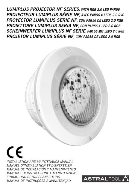
LUMIPLUS PROJECTOR NF SERIES, WITH RGB 2.0 LED PAR56<br />
PROJECTEUR LUMIPLUS SÉRIE NF, AVEC PAR56 À LEDS 2.0 RVG<br />
PROYECTOR LUMIPLUS SERIE NF, CON PAR56 DE LEDS 2.0 RGB<br />
PROIETTORE LUMIPLUS SERIA NF, CON PAR56 A LED 2.0 RGB<br />
SCHEINWERFER LUMIPLUS NF SERIE, PAR 56 MIT LEDS 2.0 RGB<br />
PROJETOR LUMIPLUS SÉRIE NF, COM PAR56 DE LEDS 2.0 RGB<br />
INSTALLATION AND MAINTENANCE MANUAL<br />
MANUEL D’INSTALLATION ET D’ENTRETIEN<br />
MANUAL DE INSTALACIÓN Y MANTENIMIENTO<br />
MANUALE DI INSTALAZIONE E MANUTENZIONE<br />
EINBAU-UND BETRIEBSANLEITUNG<br />
MANUAL DE INSTRUÇÕES E MANUTENÇÃO<br />
1
ENGLISH<br />
IMPORTANT: The instruction manual you are holding inclu<strong>de</strong>s essential information on the safety measures to be implemented for<br />
installation and start-up. Therefore, the installer as well as the user must read the instructions before beginning installation and start-up.<br />
Keep this manual for future reference.<br />
To achieve optimum performance of the NF Floodlamp follow the instructions provi<strong>de</strong>d below:<br />
1. VERIFY THE CONTENTS OF THE PACKING:<br />
The following accessories are inclu<strong>de</strong>d insi<strong>de</strong> the box:<br />
Panelled pool floodlamp:<br />
Housing body<br />
Floodlamp unit<br />
Watertight joint<br />
Clamp<br />
Bag of screws<br />
Installation and maintenance manual<br />
2. GENERAL CHARACTERISTICS:<br />
This floodlamp has been <strong>de</strong>signed to be used fully submerged un<strong>de</strong>rwater in fresh water swimming pools. It is a Class III electric apparatus with<br />
very low safety voltage (12V with alternating current).<br />
The floodlamp complies with IPX8 <strong>de</strong>gree of protection (resistance to penetration of dust, solid bodies and humidity) at a nominal immersion<br />
<strong>de</strong>pth of 2 m.<br />
This floodlamp complies with international safety standards for lights, especially the EN 60598-2-18 standard. LIGHTS PART 2: SPECIFIC<br />
REQUIREMENTS SECTION 18 LIGHTS FOR SWIMMING POOLS AND SIMILAR APPLICATIONS.<br />
The manufacturer is not responsible in any circumstances for assembly, installation or start-up of any electric components which have been<br />
inserted or handled at locations other than its own premises.<br />
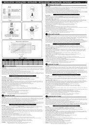
3. INSTALLATION:<br />
• Never install in vertical position with the lamp facing downwards.<br />
• In or<strong>de</strong>r to clearly light a pool it is recommen<strong>de</strong>d lo install a floodlamp every 25 m² of water surface.<br />
• In or<strong>de</strong>r to prevent glare, the floodlamps should be installed so that they face away from the resi<strong>de</strong>nce or usual view of the swimming pool.<br />
• In the event that lighting is used in training or competition pools, the floodlamps should be installed on the si<strong>de</strong>s to prevent glare on the<br />
swimmers.<br />
• To avoid the need to empty the pool to change the lamp, we recommend that the floodlamp be installed in areas which are accessible from<br />
the upper edge of the pool, at approximately 400-700 mm from the water surface (Fig. 1).<br />
Prior to installation verify that the gland seal (no. 13) has been fully tightened.<br />
The method of fastening the housing to the pool wall varies <strong>de</strong>pending on whether it is a floodlamp for concrete pools, prefabricated pools or<br />
panelled swimming pool.<br />
Panelled swimming pool with Liner<br />
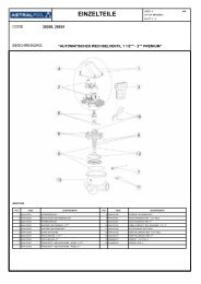
The projector can be installed in a metal sheet or plastic panelled swimming pool, using the template, and making a circular hole of 277 mm.<br />
diameter and 8 holes ∅ 4 mm (Fig. 6).<br />
Place the recess (no. 23) (The housing incorporates the joint that carries out the water tightness), through the insi<strong>de</strong> of the pool and bolt the 8<br />
DIN 7982 4.8x25 screws (no. 22) (fig. 7). Make sure that the cable outlet from the recess is on the upper si<strong>de</strong>.<br />
Place the liner.<br />
Place the clamp (no. 20) through the insi<strong>de</strong> of the pool, fasten it to the recess (no. 23) with 16 screws.<br />
Cut the Liner which is insi<strong>de</strong> the clamp, so that the recess is free and proceed to assemble the projector.<br />
4. ASSEMBLY:<br />
After installation of the housing and the clamp, if it is a prefabricated swimming pool, assemble the floodlamp.<br />
To connect the floodlamp to the electric power supply insert the cable through the gland seal nut (no. 13). Tighten the gland seal nut until you<br />
can verify that the cable will not yield when you pull on it with your hand.<br />
Take the precaution of leaving 1.5 m of cable wound on the base of the floodlamp (no. 9) in or<strong>de</strong>r to be able to remove the floodlamp to the<br />
edge of the pool in the event that lamp replacement or handling is required (Fig. 1).<br />
Before introducing the ensemble of the projector in the housing (Fig. 8), check that both of the screws (n. 1) are in the position OPEN. If it is<br />
so, introduce the projector ensemble to the housing. To obtain a good illumination of the swimming pool it is important that the anagram of the<br />
<strong>de</strong>corative ring (n. 2) remains situated at the top (Fig. 8).<br />
Turning the two screws (no. 1), the slot has to remain in vertical position (Fig. 9).<br />
5. CONTROL SYSTEMS OF THE LED LAMP:<br />
The LED lamp can be controlled in two different ways: either by a normally closed pushbutton or by means of the receiver and/or remote control<br />
In both cases, you should make sure that the voltage received by the lamp is never more than 12V.<br />
The lamp should only be operated un<strong>de</strong>rwater and anchored to the vertical walls of the pool. The lamp is supplied with heat protection, which in<br />
the event of excess temperature reduces the lighting level to avoid overheating.<br />
5.1. COLORPLUS ECO: pushbutton control<br />
The system has 14 operation mo<strong>de</strong>s: 7 set colours and 7 sequences of different colours (see section 5.1.2.) The colour or sequence is changed<br />
by a quick press of the pushbutton. The lamp/s is/are placed in white if the pushbutton is pressed for longer.<br />
5.1.1. Electrical connection diagram<br />
The COLORPLUS ECO system is composed of the projector/s, the transformer and the normally closed (NC) pushbutton.<br />
2
The transformer must be able to supply 70VA for each led lamp connected. For example, if you want to control 4 lamps, you must connect<br />
them in parallel to a transformer of at least 280VA. The pushbutton must be able to withhold the power consumed by the number of lamps<br />
installed.<br />
5.1.2. Operation mo<strong>de</strong>s<br />
The COLORPLUS ECO unit enables different light scenarios to be created insi<strong>de</strong> the swimming pool with two operation possibilities:<br />
Set colour: Selection of one set colour out of seven possibilities.<br />
COLOUR Nº<br />
COLOUR<br />
1 White<br />
2 Red<br />
3 Blue<br />
4 Green<br />
5 Purple<br />
6 Cyan<br />
7 Yellow<br />
Automatic sequence of colours: Selection of seven colour sequence programmes. Each programme is <strong>de</strong>fined by the lighting time of each colour<br />
and the transition time from one colour to another according to the following table:<br />
SEQUENCE<br />
ORDER OF COLOURS<br />
1 Red Blue Green Purple Cyan Yellow<br />
2 Red Green Cyan Blue Purple Yellow<br />
3 Purple Cyan Yellow - - -<br />
4 Red Blue Green - - -<br />
5 Purple Cyan Yellow - - -<br />
6 Yellow Purple Cyan - - -<br />
7 Green Red Blue - - -<br />
The colour or sequence is changed by pressing the pushbutton. The colour and sequence cycle is rotary. For example, if you are in colour 6, by<br />
pressing once, you will reach colour 7. If you press once again, you will go to sequence 1. If you are in sequence 7, press once and you will get<br />
to colour 2, which is Red.<br />
Colour 1, corresponds to white and is reached by one long press.<br />
5.2. COLORPLUS TOP: Modulator control and/or Remote control<br />
The system has 20 operation mo<strong>de</strong>s: 12 set colours and 8 sequences of different colours (see section 5.2.2.).<br />
The Modulator controls switching the lamps on and off, changes of colour and sequences and switching off timing.<br />
If you have a remote control, apart from the modulator operations, you can also switch colours of a sequence on and off and select the switching<br />
off time.<br />
5.2.1. Electrical connection diagram<br />
For correct installation, you will need the Modulator, the transformer and finally the leds lamp. As an option, this system can be controlled by<br />
Remote Control.<br />
The Modulator is connected to the 230 V~ac mains by means of two terminals indicated MAINS, and to the primary input of the transformer<br />
(230 V~ac) by means of the terminals indicated TRF (See attached diagram).<br />
Each Modulator, it can control until a maximum of five spotlights.<br />
The transformer must have the capacity to supply 70 VA to each led lamp connected. For example, if you want to control 4 lamps, they should<br />
be connected in parallel to a transformer of at least 280VA.<br />
Each Modulator can control up to a maximum of 12 LED spotlights.<br />
Once the unit is connected, proceed as follows to start-up the projector for the first time:<br />
• Switch on the unit by activating the 230 V~ac. at the input of the Modulator, which will automatically syntonize with the transformer. The<br />
green led of the Modulator will flash every 2 seconds and the lamp will remain off.<br />
3
5.2.2 Types of lighting<br />
The Remote Control – Modulator – Transformer – Led Projector unit enables you to create different lighting settings insi<strong>de</strong> the pool with two<br />
operation options:<br />
Set colour: Selection of a set colour among twelve possibilities.<br />
1<br />
Red 7 Sky-blue<br />
2 Green 8 Pale Violet<br />
3 Blue 9 Orange<br />
4 Yellow 10 Magenta<br />
5 Cyan 11 Emerald green<br />
6 Purple 12 White<br />
Automatic sequence of colours: Selection of eight colour sequence programmes. Each programme is <strong>de</strong>fined by the lighting time of each colour<br />
and the transition time from one colour to another according to the following table:<br />
SEQUENCE<br />
1 Red Green Blue<br />
2 Cyan Purple Yellow<br />
3 Green<br />
Emerald<br />
green<br />
4 Red Orange Green Orange<br />
5 Red Magenta Blue Magenta<br />
Cyan Sky-blue Blue Sky-blue Cyan<br />
6 Red Orange Green Cyan Blue Magenta<br />
7<br />
Pale<br />
Violet<br />
Emerald<br />
green<br />
Purple Cyan Yellow White Yellow Cyan Purple<br />
8 Red Green Blue Yellow Cyan Purple<br />
Pale<br />
Violet<br />
Sky-blue Orange Magenta<br />
Emerald<br />
green<br />
White<br />
6. MAINTENANCE:<br />
This lamp does not require any type of maintenance work. If you notice that the lamp is not working properly, please contact our customer<br />
attention service.<br />
THIS PRODUCT DOES NOT CONTAIN ANY ELEMENTS THAT CAN BE HANDLED, DISMANTLED OR REPLACED BY THE USER. IT IS<br />
FORBIDDEN TO ACCESS INSIDE THE PRODUCT, OTHERWISE THE GUARANTEE OF THE PRODUCT WILL BECOME INVALID.<br />
7. CHANGE OF LAMP:<br />
First, you have to extract the projector up to the edge of the swimming pool (Fig. 1), you must turn the 2 screws (no 1) to the position OPEN<br />
until the wedge of fixation gives up (Fig. 6 and 7).<br />
To remove the lamp, unscrew the 6 nuts (no. 10) which secure the <strong>de</strong>corative ring (no. 2) to the base of the floodlamp (no. 9) (Fig. 10).<br />
Remove the lamp (no. 6) from the insi<strong>de</strong> of the base of the floodlamp (Fig. 9) and disconnect the two terminals, loosening the two screws which<br />
secure them to the lamp (Fig. 10).<br />
Change the lamp and assemble the Floodlamp, in the opposite or<strong>de</strong>r <strong>de</strong>scribed in point 4 of assembly, taking special care to:<br />
• Connect the cable terminals to the lamp, using the 2 screws supplied with the lamp (Fig. 12).<br />
• Fully centre the 110x11 O-ring (no. 8) in its seat.<br />
• Firmly tighten the nuts.<br />
Attention:<br />
• Before any handling ensure that there is NO voltage supplied to the floodlamp.<br />
• The new lamp should have the same characteristics as that supplied with the floodlamp, of led PAR56, 12 V.<br />
• In or<strong>de</strong>r to ensure full watertightness, clean the seat of the O-ring (no. 6) for the lamp or replace the O-ring if you observe any notches or<br />
permanent damage.<br />
8. SAFETY WARNINGS:<br />
ATTENTION<br />
THE HOLES AT THE BACK OF THE LAMP (FIG. 11) SHOULD BE LEFT FREE WHEN ASSEMBLING THE PROJECTOR, SO THAT WATER<br />
CAN FLOW INSIDE FOR OPTIMUM PERFORMANCE OF THE LAMP.<br />
• The persons who are in charge of assembly should have the required qualifications for this type of work.<br />
• If the end cable of this light fitting is damaged, it should only be replaced by the manufacturer, its technical service or by a similarly qualified<br />
person, to avoid any danger.<br />
• Avoid making contact with the electric voltage.<br />
• Comply with the current standards regarding acci<strong>de</strong>nt prevention.<br />
• In this regard, the IEC 364-7-702 standards must be observed. WIRING IN BUILDINGS. SPECIAL WIRING. SWIMMING POOLS.<br />
• Any operation related to the maintenance or replacement of parts should be performed with the floodlamp disconnected from the electric<br />
power system.<br />
• Do not handle with wet feet.<br />
• The lamp is <strong>de</strong>signed TO BE USED ONLY SUBMERGED IN WATER and TO OPERATE ONLY WITH A SAFETY TRANSFORMER.<br />
• The manufacturer is not responsible in any circumstances for assembly, installation or start-up of any electric components which have been<br />
inserted or handled at locations other than its own premises.<br />
• The projector is equipped with a 2x1.5 section cable according to the power of the lamp supplied. If the lamp is changed, the cable section<br />
should be recalculated and changed if necessary.<br />
4
FRANÇAIS<br />
IMPORTANT: le manuel d’instructions que vous avez entre les mains contient <strong>de</strong>s informations <strong>de</strong> première importance sur les mesures <strong>de</strong><br />
sécurité à adopter au moment <strong>de</strong> l’installation et <strong>de</strong> la mise en service. Il est par conséquent indispensable que l’installateur et l’utilisateur<br />
lisent attentivement les instructions avant <strong>de</strong> commencer le montage et la mise en marche.<br />
Conservez ce manuel en vue <strong>de</strong> futures consultations sur le fonctionnement <strong>de</strong> cet appareil.<br />
Pour optimiser le ren<strong>de</strong>ment du Projecteur NF, il est recommandé <strong>de</strong> bien suivre les instructions qui vous sont données ci-<strong>de</strong>ssous:<br />
1. VÉRIFIER LE CONTENU DE L’EMBALLAGE :<br />
Vous <strong>de</strong>vez trouver á l'intérieur <strong>de</strong> la boîte les accessoires suivants.<br />
Projecteur pour piscine <strong>de</strong> panneaux:<br />
Corps <strong>de</strong> la niche<br />
Ensemble projecteur<br />
Joint d'étanchéité<br />
Bri<strong>de</strong><br />
Sachet <strong>de</strong> vis<br />
Manuel d’installation et d’entretien<br />
2. CARACTÉRISTIQUES GÉNÉRALES:<br />
Ce projecteur a été conçu pour être utilisé entièrement submergé dans <strong>de</strong>s piscines d'eau douce. Il s'agit d'un appareil électrique <strong>de</strong> classe III<br />
avec une tension <strong>de</strong> sécurité très basse (12 V avec courant alternatif).<br />
Le projecteur est conforme au <strong>de</strong>gré <strong>de</strong> protection IPX8 (résistance à la pénétration <strong>de</strong> la poussière, <strong>de</strong>s corps soli<strong>de</strong>s et <strong>de</strong> l'humidité). II a une<br />
profon<strong>de</strong>ur d'immersion nominale <strong>de</strong> 2 m.<br />
Ce projecteur est conforme aux normes internationales <strong>de</strong> sécurité <strong>de</strong>s luminaires, en particulier à la norme EN 60598-2-18. LUMINAIRES<br />
2ème PARTIE: CONDITIONS NÉCESSAIRES PARTICULIÈRES SECTION 18 LUMINAIRES POUR PISCINES ET APPLICATIONS SIMILAIRES.<br />
Le fabricant n'est aucunement responsable du montage, <strong>de</strong> l'installation ou <strong>de</strong> la mise en marche suite à toute manipulation ou rajout <strong>de</strong><br />
composants électriques qui ne se seraient pas produits chez lui.<br />
3. INSTALLATION:<br />
• Ne jamais installer le projecteur en position verticale avec la lampe orientée vers le bas.<br />
• Pour assurer un bon éclairage á une piscine, il est recommandé d'installer un projecteur tous les 25 m² <strong>de</strong> surface d'eau.<br />
• Pour éviter d'être aveuglé par la lumière, il faut que 1'orientation <strong>de</strong>s projecteurs soit contraire à la direction <strong>de</strong> l'habitation ou <strong>de</strong> la vue<br />
habituelle <strong>de</strong> la piscine.<br />
• SI l'éclairage est <strong>de</strong>stiné à <strong>de</strong>s piscines <strong>de</strong> compétition ou d'entraînement, les projecteurs <strong>de</strong>vront être installés sur les bords pour éviter que<br />
les nageurs soient éblouis par la lumière.<br />
• Pour éviter d'avoir à vi<strong>de</strong>r la piscine lorsqu'il faut remplacer la lampe, il est recommandé d'installer les projecteurs á <strong>de</strong>s endroits facilement<br />
accessibles à partir du bord supérieur <strong>de</strong> la piscine, à environ 400-700 mm <strong>de</strong> la surface <strong>de</strong> l'eau (Fig. 1).<br />
Avant <strong>de</strong> procé<strong>de</strong>r á l'installation, vérifier que le presse-étoupe (num. 13) est bien serré<br />
La métho<strong>de</strong> <strong>de</strong> fixation <strong>de</strong> la niche à la paroi <strong>de</strong> la piscine est différente suivant qu'il s'agit d'un projecteur pour piscine en béton, piscine<br />
préfabriquée ou piscine en polymère.<br />
Piscine en Polymère avec Liner<br />
Pour mettre un projecteur dans la piscine à panneaux, celle-ci pouvant être en tôle ou en plastique, il faut faire, en utilisant l’étiquette gabarit,<br />
un trou circulaire <strong>de</strong> 277 mm <strong>de</strong> diamètre et huit trous <strong>de</strong> 4 mm <strong>de</strong> diamètre (Fig. 6).<br />
Poser la niche (nº 23) (La niche incorpore le joint que réalise l'étanchéité), par la partie intérieure du bassin <strong>de</strong> la piscine, puis visser les 8 vis<br />
DIN 7982 4,8x25 (nº 22) (Fig. 7). Vérifier que la sortie du câble <strong>de</strong> la niche soit bien sur la partie supérieure.<br />
Puis poser le liner.<br />
Placer la bri<strong>de</strong> (nº 20) sur le côté intérieur <strong>de</strong> la piscine et la fixer à la niche (nº 23) à l’ai<strong>de</strong> <strong>de</strong>s 16 vis.<br />
Découper le liner qui est à l’intérieur <strong>de</strong> la bri<strong>de</strong>, pour que la niche soit bien dégagée, puis procé<strong>de</strong>r au montage du projecteur.<br />
4. MONTAGE:<br />
Une fois installée la niche et la bri<strong>de</strong>, dans le cas <strong>de</strong> la piscine préfabriquée, procé<strong>de</strong>r au montage du projecteur.<br />
Pour brancher le projecteur à la ligne électrique introduire le câble à travers l'écrou presse-étoupe (num. 13). Serrer l'écrou presse-étoupe et<br />
s'assurer que le câble tient bon lorsqu'on tire sur celui-ci.<br />
II faut gar<strong>de</strong>r 1,5 m <strong>de</strong> câble enroulé sur le fond du projecteur (num. 9) pour pouvoir ramener le projecteur jusqu'au bord <strong>de</strong> la piscine en cas<br />
<strong>de</strong> manipulation ou <strong>de</strong> remplacement <strong>de</strong> la lampe. (Fig. 1).<br />
Avant d'introduire l'ensemble du projecteur dans la niche (Fig. 8), vérifiez que les <strong>de</strong>ux vis (n. 1) sont dans la position OPEN. S'il est ainsi,<br />
introduisez l'ensemble <strong>de</strong> projecteur à la niche. Pour obtenir un bon éclairage <strong>de</strong> la piscine c'est important que l'anagramme <strong>de</strong> l'anneau<br />
enjoliveur (n. 2) reste située au sommet (Fig. 8).<br />
Tournant les <strong>de</strong>ux vis (no. 1), la fente <strong>de</strong>voir rester dans la position verticale (Fig. 9).<br />
5. SYSTÈMES DE CONTRÔLE DES LAMPES À LEDS :<br />
Le contrôle <strong>de</strong>s lampes à LEDS peut se faire en utilisant <strong>de</strong>ux systèmes différents : au moyen d’un bouton poussoir normalement fermé ou bien<br />
au moyen du modulateur et/ou du contrôle à distance.<br />
Dans les <strong>de</strong>ux cas, il faut vous assurer que la tension reçue par la lampe ne dépasse, en aucun cas, 12 V.<br />
La lampe ne doit fonctionner que s’il est immergé et fixé aux parois verticales <strong>de</strong> la piscine. La lampe est pourvue d’une protection thermique<br />
qui, dans le cas d’un excès <strong>de</strong> température, réduit le niveau d’éclairage pour éviter <strong>de</strong>s surchauffes.<br />
5.1. COLORPLUS ECO : contrôle au moyen d’un bouton-poussoir<br />
Le système dispose <strong>de</strong> 14 mo<strong>de</strong>s <strong>de</strong> fonctionnement : 7 couleurs fixes et 7 séquences <strong>de</strong> couleurs différentes (consulter le paragraphe 5.1.2).<br />
Chaque fois que vous appuyez brièvement, vous effectuez un changement <strong>de</strong> couleur ou <strong>de</strong> séquence. En appuyant plus longuement sur ce<br />
bouton, vous faîtes passer le/s lampe/s à la couleur blanche.<br />
5
5.1.1 Diagramme du branchement électrique<br />
Le système COLORPLUS ECO se compose du/<strong>de</strong>s lampe/s, du transformateur et du bouton-poussoir normalement fermé (NC).<br />
Le transformateur doit être dimensionné pour fournir 70VA sur chaque lampe à leds qui y est branché. Par exemple, si vous souhaitez contrôler<br />
4 projecteurs, vous <strong>de</strong>vez les connecter en parallèle à un transformateur d’au moins 280VA. Le bouton-poussoir <strong>de</strong>vra être dimensionné pour<br />
supporter la puissance consommée par le nombre <strong>de</strong>s lampes <strong>de</strong> l’installation.<br />
5.1.2. Mo<strong>de</strong>s <strong>de</strong> fonctionnement<br />
Le bloc COLORPLUS ECO permet <strong>de</strong> créer <strong>de</strong>s différentes ambiances décoratives et lumineuses à l’intérieur <strong>de</strong> la piscine avec <strong>de</strong>ux possibilités<br />
<strong>de</strong> fonctionnement :<br />
Couleur fixe : Sélection d’une couleur fixe parmi sept couleurs proposées.<br />
Nº DE COULEUR COULEUR<br />
1 Blanc<br />
2 Rouge<br />
3 Bleu<br />
4 Vert<br />
5 Pourpre<br />
6 Cyan<br />
7 Jaune<br />
Séquence automatique <strong>de</strong> couleurs : Sélection entre sept programmes <strong>de</strong> la séquence <strong>de</strong> couleurs. Chaque programme est défini par le temps<br />
<strong>de</strong> présence <strong>de</strong> chaque couleur et la durée <strong>de</strong> la transition d’une couleur à une autre selon le tableau suivant :<br />
SÉQUENCE<br />
ORDRE DES COULEURS<br />
1 Rouge Bleu Vert Pourpre Cyan Jaune<br />
2 Rouge Vert Cyan Bleu Pourpre Jaune<br />
3 Pourpre Cyan Jaune - - -<br />
4 Rouge Bleu Vert - - -<br />
5 Pourpre Cyan Jaune - - -<br />
6 Jaune Pourpre Cyan - - -<br />
7 Vert Rouge Bleu - - -<br />
Chaque fois que vous appuyez sur le bouton-poussoir, vous effectuez un changement <strong>de</strong> couleur ou <strong>de</strong> séquence. Le cycle <strong>de</strong>s couleurs et <strong>de</strong>s<br />
séquences est rotatif. Si par exemple vous avez la couleur 6, la prochaine fois que vous appuierez sur le bouton-poussoir, vous obtiendrez la<br />
couleur 7 et, si vous appuyez encore une fois <strong>de</strong>ssus, vous obtiendrez la séquence 1.<br />
Si vous êtes sur la séquence 7, en appuyant une fois <strong>de</strong> plus sur le bouton, vous obtiendrez la couleur 2 qui correspond au rouge.<br />
La couleur 1 correspond à la couleur blanche et s’obtient en appuyant longuement sur le bouton-poussoir.<br />
5.2. COLORPLUS TOP : contrôle au moyen du Modulateur et/ou du Contrôle à distance<br />
Le système dispose <strong>de</strong> 20 mo<strong>de</strong>s <strong>de</strong> fonctionnement : 12 couleurs fixes et 8 séquences <strong>de</strong> couleurs différentes (consulter le paragraphe 5.2.2).<br />
Le Modulateur permet <strong>de</strong> contrôler l’allumage et l’extinction <strong>de</strong>s projecteurs, les changements <strong>de</strong> couleurs et <strong>de</strong> séquences et une temporisation<br />
d’extinction.<br />
Si vous disposez du contrôle à distance, en plus <strong>de</strong> réaliser les fonctions du modulateur, la comman<strong>de</strong> à distance vous permettra d’activer ou <strong>de</strong><br />
désactiver la présence <strong>de</strong>s couleurs composant une séquence et <strong>de</strong> sélectionner le temps <strong>de</strong> temporisation d’extinction.<br />
5.2.1 Diagramme du branchement électrique<br />
Pour pouvoir l’installer correctement, nous avons besoin du Modulateur, du transformateur et finalement du lampe à voyants lumineux. Ce<br />
système peut, optionnellement, être contrôlé par un Contrôle à distance.<br />
Le Modulateur se branche sur le réseau électrique <strong>de</strong> 230 V~ac au moyen <strong>de</strong>s <strong>de</strong>ux bornes signalées RED et se connecte au primaire du<br />
transformateur (230 V~ac) grâce aux bornes signalées TRF (Voir schéma ci-joint).<br />
Chaque Modulateur, il peut contrôler jusqu'à un maximum <strong>de</strong> cinq projecteurs.<br />
Le transformateur doit être dimensionné pour fournir 70 VA sur chaque lampe à voyants qui est connecté. Par exemple, si nous voulons<br />
contrôler 4 lampes, nous <strong>de</strong>vons les brancher en parallèle sur un transformateur d’au moins 280VA.<br />
Chaque Modulateur peut contrôler jusqu’à un maximum <strong>de</strong> 12 projecteurs à LEDS.<br />
6
Après avoir effectué le branchement électrique, pour sa première mise en marche, procé<strong>de</strong>r comme suit :<br />
• Connectez l’ensemble en activant les 230 V~ac. à l’entrée du Modulateur et celui-ci se syntonisera automatiquement avec le transformateur.<br />
Le voyant vert du Modulateur se mettra alors à clignoter toutes les 2 sec. et la lampe restera éteint.<br />
5.2.2 Types d’éclairage<br />
L’ensemble Comman<strong>de</strong> à distance – Modulateur – Transformateur - Projecteur à voyants permet <strong>de</strong> créer différents décors lumineux à l’intérieur<br />
<strong>de</strong> la piscine avec <strong>de</strong>ux possibilités <strong>de</strong> fonctionnement :<br />
Couleur fixe : Sélection d’une couleur fixe entre douze couleurs possibles.<br />
1<br />
Rouge 7 Violet Pâle<br />
2 Vert 8 Céleste<br />
3 Bleu 9 Orange<br />
4 Jaune 10 Magenta<br />
5 Cyan 11 Vert Émerau<strong>de</strong><br />
6 Pourpre 12 Blanc<br />
Séquence automatique <strong>de</strong> couleurs : Sélection entre huit programmes <strong>de</strong> la séquence <strong>de</strong> couleurs. Chaque programme est défini par le temps <strong>de</strong><br />
présence <strong>de</strong> chaque couleur et la durée <strong>de</strong> la transition d’une couleur à une autre selon le tableau suivant :<br />
SÉQUENCE<br />
1 Rouge Vert Bleu<br />
2 Cyan Pourpre Jaune<br />
3 Vert<br />
Vert<br />
Émerau<strong>de</strong><br />
4 Rouge Orange Vert Orange<br />
5 Rouge Magenta Bleu Magenta<br />
Cyan Céleste Bleu Céleste Cyan<br />
6 Rouge Orange Vert Cyan Bleu Magenta<br />
7<br />
Violet<br />
Pâle<br />
Vert<br />
Émerau<strong>de</strong><br />
Pourpra Cyan Jaune Blanc Jaune Cyan Pourpra<br />
8 Rouge Vert Bleu Jaune Cyan Pourpra<br />
Violet<br />
Pâle<br />
Céleste Orange Magenta<br />
Vert<br />
Émerau<strong>de</strong><br />
Blanc<br />
6. ENTRETIEN:<br />
Cette lampe ne requiert aucune sorte d’entretien ; si vous observez que la lampe ne fonctionne pas correctement, veuillez prendre contact avec<br />
notre Service Client.<br />
LE PRODUIT NE CONTIENT PAS D’ÉLÉMENTS MANIPULABLES, DÉMONTABLES OU REMPLAÇABLES PAR L’UTILISATEUR ; IL EST<br />
INTERDIT D’ACCÉDER À L’INTÉRIEUR DU PRODUIT, SOUS PEINE D’EN PERDRE LA GARANTIE.<br />
7. CHANGEMENT DE LAMPE:<br />
D'abord, vous <strong>de</strong>vez extraire le projecteur jusqu'au bord <strong>de</strong> la piscine (Fig. 1), vous <strong>de</strong>vez faire <strong>de</strong>venir les 2 vis (1) à la position OPEN jusqu'à<br />
ce que la cale <strong>de</strong> la fixation abandonne (Fig. 6 et 7).<br />
Pour retirer la lampe il faut <strong>de</strong>sserrer les 6 écrous (num. 10) qui retiennent l'anneau enjoliveur (num. 2) au fond du projecteur (num. 9)<br />
(Fig. 10).<br />
Retirer la lampe (num. 6) à l'intérieur du fond du projecteur (Fig. 9) et déconnecter les 2 cosses en <strong>de</strong>sserrant les <strong>de</strong>ux vis qui les retiennent à<br />
la lampe (Fig. 10).<br />
Changer la lampe et procé<strong>de</strong>r au montage du projecteur, effectuer l'opération inverse à celle qui vient d'être décrite au point 4 du montage, en<br />
faisant bien attention aux points suivants :<br />
• Connecter les cosses du câble à la lampe, en utilisant les 2 vis fourmes avec la lampe (Fig. 12).<br />
• Placer le joint torique 110x11 (num. 8) bien centré dans son logement.<br />
• Bien serrer tous les écrous.<br />
Attention :<br />
• Avant toute manipulation, s'assurer que le projecteur N'EST PAS sous tension.<br />
• La lampe neuve doit avoir les mêmes caractéristiques que celle fournie avec le projecteur, lampe à leds PAR56 , 12 V.<br />
• Pour que l'étanchéité soit parfaite, il faut nettoyer l'assiette du joint torique (num, 6) <strong>de</strong> la lampe ou le remplacer si l'on y a observé une<br />
entaille ou n’importe quelle déformation permanente.<br />
ATTENTION<br />
LES ORIFICES SITUÉS À L’ARRIÈRE DE LA LAMPE (FIG. 11) DOIVENT ÊTRE DÉGAGÉS LORS DU MONTAGE SUR LE PROJECTEUR<br />
POUR PERMETTRE À L’EAU DE PÉNÉTRER À L’INTÉRIEUR, AFIN D’OBTENIR UN RENDEMENT OPTIMAL DE LA LAMPE.<br />
7
8. AVERTISSEMENTS CONCERNANT LA SÉCURITÉ:<br />
• Les personnes chargées du montage doivent avoir la qualification requise pour ce genre <strong>de</strong> travail.<br />
• Au cas où le bout du câble <strong>de</strong> ce luminaire était abîmé, il faudrait le faire remplacer exclusivement par le fabriquant ou son service technique<br />
ou bien par une personne possédant une qualification similaire en vue d’éviter un possible danger.<br />
• II faut éviter tout contact avec la tension électrique.<br />
• II faut respecter les normes <strong>de</strong> prévention <strong>de</strong>s acci<strong>de</strong>nts en vigueur.<br />
• Pour ce faire, il faut en particulier respecter les normes IEC 364-7-702 • INSTALLATIONS ÉLECTRIQUES DANS L'INTÉRIEUR DES<br />
BÂTIMENTS, INSTALLATIONS SPÉCIALES. PISCINES,<br />
• Toute opération <strong>de</strong> maintenance ou <strong>de</strong> remplacement <strong>de</strong>s pièces doit être précédée <strong>de</strong> la déconnexion du projecteur du réseau électrique.<br />
• Ne pas le manipuler avec les pieds mouillés.<br />
• La lampe est conçue POUR ÊTRE UTILISÉE UNIQUEMENT IMMERGÉE DANS L’EAU et POUR FONCTIONNER UNIQUEMENT AVEC UN<br />
TRANSFORMATEUR DE SÉCURITÉ.<br />
• Le fabricant n'est aucunement responsable du montage, <strong>de</strong> l'installation ou <strong>de</strong> la mise en marche suite à toute manipulation ou rajout <strong>de</strong><br />
composants électriques qui ne se seraient pas produits chez lui.<br />
• Le projecteur est équipé d’un câble à section 2 x 1,5 conformément à la puissance <strong>de</strong> la lampe qui est fournie ; si vous changez <strong>de</strong> lampe, il<br />
faut recalculer la section du câble et le remplacer, si besoin est.<br />
8
ESPAÑOL<br />
IMPORTANTE: El manual <strong>de</strong> instrucciones que usted tiene en sus manos, contiene información fundamental acerca <strong>de</strong> las medidas <strong>de</strong><br />
seguridad a adoptar a la hora <strong>de</strong> la <strong>instalación</strong> y la puesta en servicio. Por ello, es imprescindible que tanto el instalador como el usuario<br />
lean las instrucciones antes <strong>de</strong> pasar al montaje y la puesta en marcha.<br />
Conserve este manual para futuras consultas acerca <strong>de</strong>l funcionamiento <strong>de</strong> este aparato.<br />
Para conseguir un óptimo rendimiento <strong>de</strong>l Proyector NF, es conveniente observar las instrucciones que se indican a continuación:<br />
1. COMPRUEBE EL CONTENIDO DEL EMBALAJE:<br />
En el interior <strong>de</strong> la caja encontrará los siguientes accesorios:<br />
Proyector piscina <strong>de</strong> paneles<br />
Cuerpo nicho<br />
Conjunto proyector<br />
Junta adhesiva <strong>de</strong> estanqueidad<br />
Brida<br />
Bolsa <strong>de</strong> tornillos<br />
Etiqueta Plantilla<br />
<strong>Manual</strong> <strong>de</strong> <strong>instalación</strong> y <strong>mantenimiento</strong><br />
2. CARACTERÍSTICAS GENERALES:<br />
Este proyector ha sido diseñado para utilizarse totalmente sumergido en piscinas <strong>de</strong> agua dulce. Se trata <strong>de</strong> un aparato eléctrico <strong>de</strong> clase III con<br />
una muy baja tensión <strong>de</strong> seguridad (12 V con corriente alterna).<br />
El proyector cumple con el grado <strong>de</strong> protección IPX8 (resistencia a la penetración <strong>de</strong> polvo, a los cuerpos sólidos y a la humedad) con una<br />
profundidad <strong>de</strong> inmersión nominal <strong>de</strong> 2 m.<br />
Este proyector cumple con las normas internacionales <strong>de</strong> seguridad <strong>de</strong> luminarias, en especial la norma EN 60598-2-18: LUMINARIAS PARTE<br />
2: REQUERIMIENTOS PARTICULARES SECCIÓN 18 LUMINARIAS PARA PISCINAS Y APLICACIONES SIMILARES.<br />
El fabricante en ningún caso se responsabiliza <strong>de</strong>l montaje, <strong>instalación</strong> o puesta en funcionamiento <strong>de</strong> cualquier manipulación o incorporación<br />
<strong>de</strong> componentes eléctricos que no se hayan llevado a cabo en sus instalaciones.<br />
3. INSTALACIÓN:<br />
• El proyector únicamente <strong>de</strong>be funcionar sumergido y fijado a las pare<strong>de</strong>s verticales <strong>de</strong> la piscina. No encen<strong>de</strong>r nunca el proyector si no está<br />
sumergido en agua. No instalar nunca en posición vertical con la lámpara hacia arriba.<br />
• Para iluminar claramente una piscina se recomienda instalar un proyector cada 25 m 2<br />
<strong>de</strong> superficie <strong>de</strong> agua.<br />
• A fin <strong>de</strong> evitar <strong>de</strong>slumbramientos, los proyectores <strong>de</strong>ben instalarse orientados en sentido contrario <strong>de</strong> la vivienda o vista habitual <strong>de</strong> la<br />
piscina.<br />
• En caso <strong>de</strong> utilizar iluminación en piscinas <strong>de</strong> competición o entrenamiento, los proyectores <strong>de</strong>berán instalarse en los laterales pera evitar el<br />
<strong>de</strong>slumbramiento <strong>de</strong> los nadadores.<br />
• Para evitar el vaciado <strong>de</strong> la piscina en caso <strong>de</strong> recambio <strong>de</strong> la lámpara se recomienda la <strong>instalación</strong> <strong>de</strong>l proyector en lugares accesibles <strong>de</strong>s<strong>de</strong><br />
el bor<strong>de</strong> superior <strong>de</strong> la piscina, a unos 400-700 mm <strong>de</strong> la superficie <strong>de</strong>l agua (Fig. 1).<br />
Antes <strong>de</strong> instalar comprobar que el cuerpo prensaestopas (nº 13) esté bien apretado.<br />
El método <strong>de</strong> fijación <strong>de</strong>l nicho a la pared <strong>de</strong> la piscina varía según sea un proyector para piscina <strong>de</strong> hormigón, piscina prefabricada o piscina <strong>de</strong><br />
paneles.<br />
Piscina <strong>de</strong> Paneles con Liner<br />
Para colocar un proyector en la piscina <strong>de</strong> paneles, ésta pue<strong>de</strong> ser <strong>de</strong> chapa o <strong>de</strong> plástico, <strong>de</strong>be realizarse, con la ayuda <strong>de</strong> la etiqueta plantilla,<br />
un agujero circular <strong>de</strong> 277 mm <strong>de</strong> diámetro y 8 agujeros <strong>de</strong> Ø 4mm (Fig. 6).<br />
Colocar el nicho (nº 23) (El nicho incorpora la junta que realiza la estanqueidad), por la parte interior <strong>de</strong>l vaso piscina, y atornillar los 8 tornillos<br />
DIN 7982 4,8x25 (nº 22) (Fig. 7). Asegurarse que la salida <strong>de</strong>l cable <strong>de</strong>l nicho queda en la parte superior.<br />
Colocar el liner.<br />
Proce<strong>de</strong>r a la colocación <strong>de</strong> la brida (nº 20) por el lado interior <strong>de</strong> la piscina, fijarla en el nicho (nº 23) mediante 16 tornillos.<br />
Recortar el Liner que queda en el interior <strong>de</strong> la brida, para que el nicho que<strong>de</strong> libre y proce<strong>de</strong>r al montaje <strong>de</strong>l proyector.<br />
4. MONTAJE:<br />
Una vez instalado el nicho, y la brida en el caso <strong>de</strong> la piscina prefabricada, pue<strong>de</strong> proce<strong>de</strong>r al montaje <strong>de</strong>l proyector.<br />
Para conectar el proyector a la red eléctrica <strong>de</strong>be introducir el cable a través <strong>de</strong> la tuerca prensaestopas (nº 13). Apriete la tuerca prensaestopas<br />
hasta asegurarse que al tirar <strong>de</strong>l cable con la mano éste no ce<strong>de</strong>.<br />
Debe tener la precaución <strong>de</strong> <strong>de</strong>jar 1,5 m <strong>de</strong> cable enrollados en el fondo <strong>de</strong>l proyector (nº 9) para po<strong>de</strong>r extraer el proyector hasta el bor<strong>de</strong> <strong>de</strong> la<br />
piscina en caso <strong>de</strong> manipulación o cambio <strong>de</strong> la lámpara. (Fig. 1).<br />
Antes <strong>de</strong> introducir el conjunto <strong>de</strong>l proyector en el nicho (Fig. 8) comprobar que los tornillos nº 1 están en posición OPEN, si es así introducir el<br />
conjunto proyector al nicho. Para obtener una buena iluminación <strong>de</strong> la piscina es importante que el anagrama <strong>de</strong>l anillo embellecedor (nº 2)<br />
que<strong>de</strong> situado en la parte superior (Fig. 8).<br />
Girar los dos tornillos (nº 1), la ranura <strong>de</strong>be quedar en posición vertical (Fig. 9).<br />
5. SISTEMAS DE CONTROL DE LOS PROYECTORES NF DE LEDS COLORPLUS<br />
El control <strong>de</strong> las lámparas <strong>de</strong> LEDS pue<strong>de</strong> realizarse mediante dos sistemas diferentes: mediante un pulsador normalmente cerrado o bien<br />
mediante el modulador y/o el control remoto.<br />
En ambos casos <strong>de</strong>be asegurarse que bajo ningún concepto la tensión que reciba la lámpara sea superior a 12 V.<br />
La lámpara únicamente <strong>de</strong>be funcionar sumergido y fijada a las pare<strong>de</strong>s verticales <strong>de</strong> la piscina. La lámpara va provista <strong>de</strong> una protección<br />
térmica que, en el caso <strong>de</strong> un exceso <strong>de</strong> temperatura, reduce el nivel <strong>de</strong> iluminación para evitar sobrecalentamientos.<br />
9
5.1. COLORPLUS ECO: control mediante pulsador<br />
El sistema dispone <strong>de</strong> 14 modos <strong>de</strong> funcionamiento: 7 colores fijos y 7 secuencias <strong>de</strong> colores diferentes (consultar apartado 5.1.2). Mediante<br />
cada pulsación corta efectuamos un cambio <strong>de</strong> color o <strong>de</strong> secuencia. Mediante una pulsación larga situamos el/las lámpara/s en el color blanco.<br />
5.1.1. Diagrama <strong>de</strong> conexionado eléctrico<br />
El sistema COLORPLUS ECO está compuesto por el/las lámpara/s, el transformador y el pulsador normalmente cerrado (NC).<br />
El transformador ha <strong>de</strong> estar dimensionado para suministrar 70VA por cada lámpara <strong>de</strong> leds que se conecte. Por ejemplo, si <strong>de</strong>seamos controlar<br />
4 lámparas <strong>de</strong>bemos conectarlas en paralelo a un transformador <strong>de</strong> cómo mínimo 280VA. El pulsador <strong>de</strong>berá estar dimensionado para soportar<br />
la potencia consumida por el número <strong>de</strong> lámparas <strong>de</strong> la <strong>instalación</strong>.<br />
5.1.2. Modos <strong>de</strong> funcionamiento<br />
El conjunto COLORPLUS ECO permite crear distintos escenarios luminosos en el interior <strong>de</strong> la piscina con dos posibilida<strong>de</strong>s <strong>de</strong> funcionamiento:<br />
Color fijo: Selección <strong>de</strong> un color fijo entre siete posibles.<br />
Nº DE COLOR COLOR<br />
1 Blanco<br />
2 Rojo<br />
3 Azul<br />
4 Ver<strong>de</strong><br />
5 Púrpura<br />
6 Cian<br />
7 Amarillo<br />
Secuencia automática <strong>de</strong> colores: Selección entre siete programas <strong>de</strong> la secuencia <strong>de</strong> colores. Cada programa viene <strong>de</strong>finido por el tiempo <strong>de</strong><br />
presencia <strong>de</strong> cada color y la duración <strong>de</strong> la transición <strong>de</strong> un color a otro según la siguiente tabla:<br />
Secuencia<br />
Or<strong>de</strong>n <strong>de</strong> los colores<br />
1 Rojo Azul Ver<strong>de</strong> Púrpura Cian Amarillo<br />
2 Rojo Ver<strong>de</strong> Cian Azul Púrpura Amarillo<br />
3 Púrpura Cian Amarillo - - -<br />
4 Rojo Azul Ver<strong>de</strong> - - -<br />
5 Púrpura Cian Amarillo - - -<br />
6 Amarillo Púrpura Cian - - -<br />
7 Ver<strong>de</strong> Rojo Azul - - -<br />
Mediante cada pulsación efectuamos un cambio <strong>de</strong> color o secuencia. El ciclo <strong>de</strong> colores y secuencias es rotativo. Si por ejemplo tenemos el<br />
color 6, en la siguiente pulsación obtendremos el color 7, si volvemos a pulsar, obtendremos la secuencia 1. Si estamos en la secuencia 7, en la<br />
siguiente pulsación vamos a obtener el color 2 que correspon<strong>de</strong> al Rojo.<br />
El color 1, correspon<strong>de</strong> al color blanco y se obtiene mediante una pulsación larga.<br />
5.2. COLORPLUS TOP: control mediante el Modulador y/o el Control Remoto<br />
El sistema dispone <strong>de</strong> 20 modos <strong>de</strong> funcionamiento: 12 colores fijos y 8 secuencias <strong>de</strong> colores diferentes (consultar apartado 5.2.2).<br />
Mediante el Modulador se controla el encendido y apagado <strong>de</strong> las lámparas, los cambios <strong>de</strong> colores y secuencias y una temporización <strong>de</strong><br />
apagado.<br />
En caso <strong>de</strong> disponer <strong>de</strong> control remoto, a<strong>de</strong>más <strong>de</strong> realizar las funciones <strong>de</strong>l Modulador, el mando a distancia nos permitirá activar o <strong>de</strong>sactivar<br />
la presencia <strong>de</strong> los colores que componen una secuencia y seleccionar el tiempo <strong>de</strong> temporización <strong>de</strong> apagado.<br />
5.2.1. Diagrama <strong>de</strong> conexionado eléctrico<br />
Para una correcta <strong>instalación</strong>, necesitamos el Modulador, el transformador y la lámpara <strong>de</strong> leds. Opcionalmente este sistema pue<strong>de</strong> ser<br />
controlado por Control Remoto.<br />
El Modulador se conecta a la red eléctrica <strong>de</strong> 230 V~ac mediante los dos bornes indicados como RED y se conecta al primario <strong>de</strong>l transformador<br />
(230 V~ac) mediante los bornes indicados con TRF (ver esquema adjunto).<br />
El transformador ha <strong>de</strong> estar dimensionado para suministrar 70VA por cada lámpara <strong>de</strong> leds que se conecte. Por ejemplo, si <strong>de</strong>seamos controlar<br />
4 lámparas <strong>de</strong>bemos conectarlos en paralelo a un transformador <strong>de</strong> cómo mínimo 280VA.<br />
Cada Modulador pue<strong>de</strong> controlar hasta un máximo <strong>de</strong> 12 lámparas <strong>de</strong> LEDs.<br />
10
Después <strong>de</strong> efectuar la conexión eléctrica, para su primera puesta en marcha, operar como sigue:<br />
• Dar alimentación al conjunto activando los 230 V~ac. a la entrada <strong>de</strong>l Modulador y este se sintonizará <strong>de</strong> forma automática con el<br />
transformador. El led ver<strong>de</strong> <strong>de</strong>l Modulador efectuará un parpa<strong>de</strong>o cada 2 seg. y la lámpara permanecerá apagada.<br />
5.2.2. Modos <strong>de</strong> funcionamiento<br />
El conjunto Mando a Distancia – Modulador – Transformador - Lámpara <strong>de</strong> leds, permite crear distintos escenarios luminosos en el interior <strong>de</strong> la<br />
piscina con dos posibilida<strong>de</strong>s <strong>de</strong> funcionamiento:<br />
Color fijo: Selección <strong>de</strong> un color fijo entre doce posibles.<br />
1 Rojo 7 Violeta pálido<br />
2 Ver<strong>de</strong> 8 Celeste<br />
3 Azul 9 Naranja<br />
4 Amarillo 10 Magenta<br />
5 Cian 11 Ver<strong>de</strong> esmeralda<br />
6 Púrpura 12 Blanco<br />
Secuencia automática <strong>de</strong> colores: Selección entre ocho programas <strong>de</strong> la secuencia <strong>de</strong> colores. Cada programa viene <strong>de</strong>finido por el tiempo <strong>de</strong><br />
presencia <strong>de</strong> cada color y la duración <strong>de</strong> la transición <strong>de</strong> un color a otro según la siguiente tabla:<br />
SECUENCIA<br />
1 Rojo Ver<strong>de</strong> Azul<br />
2 Cian Púrpura Amarillo<br />
3 Ver<strong>de</strong><br />
Ver<strong>de</strong><br />
esmeralda<br />
Cian Celeste Azul Celeste Cian<br />
4 Rojo Naranja Ver<strong>de</strong> Naranja<br />
5 Rojo Magenta Azul Magenta<br />
Ver<strong>de</strong><br />
esmeralda<br />
6 Rojo Naranja Ver<strong>de</strong> Cian Azul Magenta<br />
7<br />
Violeta<br />
Pálido<br />
Púrpura Cian Amarillo Blanco Amarillo Cian Púrpura<br />
8 Rojo Ver<strong>de</strong> Azul Amarillo Cian Púrpura<br />
Violeta<br />
Pálido<br />
Celeste Naranja Magenta<br />
Ver<strong>de</strong><br />
Esmeralda<br />
Blanco<br />
Por ejemplo, el programa 5 indica que cada color permanece 30 segundos, <strong>de</strong> los que 22 presentan un color fijo y 8 son empleados para hacer<br />
la transición al siguiente color. El programa 8 indica que los 60 segundos correspondientes a cada color se utilizan para hacer la transición al<br />
siguiente.<br />
6. MANTENIMIENTO:<br />
La lámpara <strong>de</strong> LEDS no necesita <strong>de</strong> ningún tipo <strong>de</strong> <strong>mantenimiento</strong>, si <strong>de</strong>tectan que la lámpara no funciona correctamente por favor pónganse en<br />
contacto con nuestro <strong>de</strong>partamento <strong>de</strong> atención al cliente.<br />
LA LÁMPARA NO CONTIENE ELEMENTOS MANIPULABLES, DESMONTABLES O SUBSTITUIBLES POR EL USUARIO, ESTÀ PROHIBIDO<br />
ACCEDER AL INTERIOR DEL PRODUCTO, SE PERDERIA LA GARANTIA DEL PRODUCTO.<br />
7. CAMBIO DE LÁMPARA:<br />
Primero se <strong>de</strong>be extraer el proyector hasta el bor<strong>de</strong> <strong>de</strong> la piscina (Fig. 1) se <strong>de</strong>ben girar los 2 tornillos (nº 1) a la posición OPEN hasta que la<br />
cuña <strong>de</strong> fijación ceda (Fig. 6 y 7).<br />
Para extraer la lámpara <strong>de</strong>be <strong>de</strong>senroscar las 6 tuercas (nº 10) que fijan el anillo embellecedor (nº 2) al fondo proyector (nº 9) (Fig. 10).<br />
Extraer la lámpara (nº 6) <strong>de</strong>l interior <strong>de</strong>l fondo proyector (Fig. 9) y <strong>de</strong>sconectar los 2 terminales, aflojando los dos tornillos que los fijan a la<br />
lámpara. (Fig. 10).<br />
Cambiar la lámpara y proce<strong>de</strong>r al montaje <strong>de</strong>l Proyector, <strong>de</strong> modo inverso al <strong>de</strong>scrito en el punto 4 <strong>de</strong> montaje, teniendo especial cuidado en:<br />
• Conectar los terminales <strong>de</strong>l cable a la lámpara, utilizando los 2 tornillos suministrados con la lámpara (Fig. 12).<br />
• Poner la Junta tórica 110x11 (nº 8) bien centrada en su alojamiento.<br />
• Apretar bien todas las tuercas.<br />
Atención:<br />
• Antes <strong>de</strong> cualquier manipulación asegurarse que el proyector NO recibe tensión.<br />
• La lámpara nueva <strong>de</strong>be reunir las mismas características que la suministrada, PAR56 <strong>de</strong> Leds, 12V.<br />
• Para asegurar una perfecta estanqueidad <strong>de</strong>be limpiarse el asiento <strong>de</strong> la junta tórica (nº 6) <strong>de</strong> la lámpara o bien sustituir esta si se observa en<br />
ella alguna entalla o <strong>de</strong>formación permanente.<br />
ATENCIÓN<br />
LOS AGUJEROS DE LA PARTE POSTERIOR DE LA LÁMPARA (FIG. 11) DEBEN ESTAR LIBRES EN EL MONTAJE CON EL PROYECTOR PARA<br />
QUE PUEDA ENTRAR AGUA EN EL INTERIOR Y OBTENER ASÍ UN OPTIMO RENDIMIENTO DE LA LÁMPARA.<br />
11
8. ADVERTENCIAS DE SEGURIDAD:<br />
• Las personas que se encarguen <strong>de</strong>l montaje <strong>de</strong>ben poseer la calificación requerida para este tipo <strong>de</strong> trabajos.<br />
• En el caso <strong>de</strong> que el cable extremo <strong>de</strong> esta luminaria estuviera dañado, este <strong>de</strong>be ser reemplazado exclusivamente por el fabricante o su<br />
servició técnico o por una persona <strong>de</strong> calificación similar para evitar un posible peligro.<br />
• Se <strong>de</strong>be evitar entrar en contacto con la tensión eléctrica.<br />
• Se <strong>de</strong>ben respetar las normas vigentes para la prevención <strong>de</strong> acci<strong>de</strong>ntes.<br />
• A tal respecto, se <strong>de</strong>ben cumplir las normas IEC 364-7-702: INSTALACIONES ELÉCTRICAS EN EDIFICIOS. INSTALACIONES ESPECIALES.<br />
PISCINAS.<br />
• Cualquier operación <strong>de</strong> <strong>mantenimiento</strong> o sustitución <strong>de</strong> piezas <strong>de</strong>be realizarse con el proyector <strong>de</strong>sconectado <strong>de</strong> la red.<br />
• No manipular con los pies mojados.<br />
• La lámpara está diseñada PARA USAR ÚNICAMENTE SUMERGIDA EN AGUA y está concebida PARA FUNCIONAR ÚNICAMENTE CON UN<br />
TRANSFORMADOR DE SEGURIDAD.<br />
• El fabricante en ningún caso se responsabiliza <strong>de</strong>l montaje, <strong>instalación</strong> o puesta en funcionamiento <strong>de</strong> cualquier manipulación o<br />
incorporación <strong>de</strong> componentes eléctricos que no se hayan llevado a cabo en sus instalaciones.<br />
12
ITALIANO<br />
IMPORTANTE: Il manuale d’istruzioni in suo possesso contiene informazioni fondamentali sulle misure di sicurezza da adottare per<br />
l'installazione e la messa in servizio. Per ciò è imprescindibile che sia l’installatore che l’utente leggano le istruzioni prima di iniziare il<br />
montaggio e la messa in servizio.<br />
Conservi questo manuale per poter consultare in futuro in merito al funzionamento di questo apparecchio.<br />
Per ottenere un ottimo rendimento <strong>de</strong>llo Proiettore NF, è conveniente fare attenzione alle seguenti istruzioni:<br />
1. CONTROLLARE IL CONTENUTO DELL'IMBALLAGGIO:<br />
Nella cassa troverà i seguenti accessori:<br />
Proiettore piscina di panelli:<br />
Corpo nicchia<br />
Insieme proiettore<br />
Guarnizione di tenuta<br />
Flangia<br />
Sacchetto viti<br />
<strong>Manual</strong>e di installazione e manutenzione<br />
2. CARATTERISTICHE GENERALI:<br />
Questo proiettore è stato disegnato per essere utilizzato totalmente sommerso nelle piscine d'acqua dolce. Si tratta di un apparecchio elettrico di<br />
classe III con una bassissima tensione di sicurezza (12 V con corrente alternata).<br />
II proiettore compie con iI grado di protezione IPX8 (resistenza alla penetrazione <strong>de</strong>lla polvere, al corpi solidi e all'umidità) con una profondità<br />
d'immersione nominale di 2m.<br />
Questo proiettore segue le norme internazionali di sicurezza d'illuminazione, specialmente la norma EN 60598-2-18: ILLUMINAZIONE PARTE<br />
2-. PRESCRIZIONI PARTICOLARI SEZiONE 18 ILLUMINAZIONE PER PISCINE E APPLICAZIONI SIMILARI.<br />
II fabbricante rifiuta qualsiasi responsabilità per il montaggio, I'installazione o la messa in funzione di componenti elettrici che sono stati<br />
manipolati o introdotti al di fuori <strong>de</strong>i suoi stabilimenti.<br />
3. INSTALLAZIONE:<br />
• Non installare mal in posizione verticale con la lampada verso il basso,<br />
• Per ben illuminare una piscina, si raccomanda d'installare un proiettore per ogni 25 m² di superficie d'acqua.<br />
• Per evitare abbagliamenti, i proiettori dovranno essere installati orientati nel senso contrario <strong>de</strong>lla casa o <strong>de</strong>lla vista abituale <strong>de</strong>lla piscina.<br />
• Nel caso si usi l’illuminazione in piscine di competizione o allenamento, i proiettori dovranno essere installati lateralmente per evitare<br />
l'abbagliamento <strong>de</strong>i nuotatori.<br />
• Per evitare di dover vuotare la piscina per poter cambiare la lampada, é raccomandato d'installare il proiettore in luoghi accessibili dal bordo<br />
superiore <strong>de</strong>lla piscina, 400-700 mm dalla superficie <strong>de</strong>ll'acqua (Fig.1).<br />
Prima d'installare, verificare che iI premistoppa (n. 13) sia stretto bene.<br />
II metodo per fissare la nicchia alla parete <strong>de</strong>lla piscina varia a secondo se si tratta di un proiettore per piscine in cemento, prefabbricate o<br />
piscina di panelli.<br />
Piscina di Panelli con Liner<br />
Per collocare un proiettore nella piscina a pannelli, sia che essa sia di lamiera o di plastica, utilizzando una etichetta come mo<strong>de</strong>llo, si <strong>de</strong>ve<br />
realizzare un foro circolare di 277 mm di diametro e 8 fori da Ø 4 mm (Fig. 6).<br />
Collocare la nicchia (nº 23) (La nicchia incorpora la guarnizione che esegue l’isolamento), attraverso la parte interiore <strong>de</strong>lla vasca <strong>de</strong>lla piscina e<br />
avvitare le 8 viti DIN 7982 4,8 x 25 (nº 22) (Fig. 7). Assicurarsi che l’uscita <strong>de</strong>l cavo dalla nicchia rimanga nella parte superiore.<br />
Collocare il liner.<br />
Proce<strong>de</strong>re alla collocazione <strong>de</strong>lla flangia (nº 20) attraverso il lato interno <strong>de</strong>lla piscina, fissarla nella nicchia (nº 23) per mezzo di 16 viti.<br />
Ritagliare il liner che rimane all’interno <strong>de</strong>lla flangia, affinché la nicchia rimanga libera, e proce<strong>de</strong>re al montaggio <strong>de</strong>l proiettore.<br />
4. MONTAGGIO:<br />
Una volta installata la nicchia, e la flangia nel caso <strong>de</strong>lla piscina prefabbricata, si può proce<strong>de</strong>re al montaggio <strong>de</strong>l proiettore,<br />
Per collegare il proiettore alla rete elettrica, inserire il cavo attraverso iI dado premistoppa (n. 13), Stringere il dado premistoppa fino ad essere<br />
sicuri che tirando iI cavo con la mano, questo non ceda.<br />
Si <strong>de</strong>ve avere la precauzione di lasciare 1,5 m di cavo arrotolato nel corpo <strong>de</strong>l proiettore (n. 9) per poter estrarre il proiettore fino al bordo <strong>de</strong>lla<br />
piscina in caso di manipolazione o cambio <strong>de</strong>lla lampada (Fig. 1).<br />
Prima di introdurre l'insieme <strong>de</strong>l proiettore nella nicchia (Fig. 8), controllare che entrambe le viti (n. 1) sono nella posizione OPEN. Se è così,<br />
introdurre l'ensemble proiettore alla nicchia. Per ottenere una buona illuminazione <strong>de</strong>lla piscina è importante che l'anagramma <strong>de</strong>ll'anello<br />
<strong>de</strong>corativo (n. 2) rimane situata alla cima (Fig. 8).<br />
Girando le due viti (n. 1), lo slot è di rimanere in posizione verticale (Fig. 9).<br />
5. SISTEMI DI CONTROLLO DEI PROIETTORI A LED<br />
Il controllo <strong>de</strong>i proiettori a LED si può realizzare per mezzo di due sistemi diversi: mediante un pulsante normalmente chiuso oppure mediante il<br />
Modulatore e/o il controllo a distanza.<br />
In entrambi i casi si ren<strong>de</strong>rà necessario assicurarsi che la tensione che riceva la lampada non sia superiore a 12 V, per nessun concetto.<br />
Il proiettore <strong>de</strong>ve funzionare unicamente sotto l’acqua, fissato alle pareti verticali <strong>de</strong>lla piscina. Il faretto è dotato di una protezione termica che,<br />
nel caso di un eccesso di temperatura, riduce il livello d’illuminazione allo scopo di evitare <strong>de</strong>i surriscaldamenti.<br />
5.1. COLORPLUS ECO: controllo mediante pulsante<br />
Il sistema dispone di 14 modalità di funzionamento: 7 colori fissi e 7 sequenze di colori diversi (vedi paragrafo 5.1.2.). Per ogni pressione breve<br />
<strong>de</strong>l pulsante si effettuerà un cambio di colore o di sequenza. Con una pressione lunga si passerà/anno il/i proiettore/i sul colore bianco.<br />
5.1.1 Diagramma di connessione elettrica<br />
Il sistema COLORPLUS ECO è composto dal/i proiettore/i, il trasformatore e il pulsante normalmente chiuso (NC).<br />
Il trasformatore <strong>de</strong>ve essere dimensionato in maniera tale da fornire 70 VA per ogni faretto a led che venga allacciato. Per esempio, se si<br />
<strong>de</strong>si<strong>de</strong>ra controllare 4 faretti, si ren<strong>de</strong>rà necessario connetterli in parallelo ad un trasformatore con un minimo di 270 VA. Il pulsante dovrà<br />
essere dimensionato in maniera tale da sopportare la potenza consumata dal numero di proiettori <strong>de</strong>ll’installazione.<br />
13
5.1.2. Modalità di funzionamento<br />
L’insieme COLORPLUS ECO permette di creare vari scenari luminosi all’interno <strong>de</strong>lla piscina, con due diverse possibilità di funzionamento:<br />
Colore fisso: selezione di un colore fisso tra sette possibilità.<br />
Nº DE COLORE COLORE<br />
1 Bianco<br />
2 Rosso<br />
3 Blu<br />
4 Ver<strong>de</strong><br />
5 Porpora<br />
6 Ciano<br />
7 Giallo<br />
Sequenza automatica di colori: selezione tra sette programmi <strong>de</strong>lla sequenza di colori. Ogni programma viene <strong>de</strong>finito dal tempo di presenza di<br />
ogni colore e la durata <strong>de</strong>lla transizione da un colore all’altro, in base alla seguente tabella:<br />
SEQUENZA<br />
ORDINE DEI COLORI<br />
1 Rosso Blu Ver<strong>de</strong> Porpora Ciano Giallo<br />
2 Rosso Ver<strong>de</strong> Ciano Blu Porpora Giallo<br />
3 Porpora Ciano Giallo - - -<br />
4 Rosso Blu Ver<strong>de</strong> - - -<br />
5 Porpora Ciano Giallo - - -<br />
6 Giallo Porpora Ciano - - -<br />
7 Ver<strong>de</strong> Rosso Blu - - -<br />
Mediante ogni pressione <strong>de</strong>l pulsante si realizzerà un cambio di colore o di sequenza. Il ciclo di colori e sequenze è rotativo. Se per esempio<br />
abbiamo il colore 5, alla seguente pressione si otterrà il colore 6, e se si preme di nuovo si otterrà la sequenza 1. Se ci troviamo nella sequenza<br />
7, alla seguente pressione si otterrà il colore 2 che corrispon<strong>de</strong> al rosso.<br />
Il colore 1, corrispon<strong>de</strong> al colore bianco e si ottiene mediante una pressione lunga.<br />
5.2. COLORPLUS TOP: controllo mediante il Modulatore e/o il controllo a distanza<br />
Il sistema dispone di 20 modalità di funzionamento: 12 colori fissi e 8 sequenze di colori diversi (vedi paragrafo 5.2.2).<br />
Mediante il Modulatore si controlla l’accensione e lo spegnimento <strong>de</strong>i faretti, il cambio <strong>de</strong>i colori e <strong>de</strong>lle sequenze e un timer per lo<br />
spegnimento.<br />
In caso di disporre di controllo a distanza, oltre a realizzare le funzioni <strong>de</strong>l Modulatore, il comando a distanza consente di attivare o disattivare la<br />
presenza <strong>de</strong>i colori che compongono una sequenza e selezionare il tempo <strong>de</strong>l timer di spegnimento.<br />
5.2.1 Diagramma di connessione elettrica<br />
Per una corretta installazione, si ren<strong>de</strong>rà necessario disporre <strong>de</strong>l Modulatore, <strong>de</strong>l trasformatore e <strong>de</strong>l faro a led. In forma opzionale, questo<br />
sistema può essere controllato con un controllo a distanza.<br />
Il Modulatore si connette alla rete elettrica da 230 V~ac per mezzo <strong>de</strong>i due morsetti indicati come RETE e si connette al primario <strong>de</strong>l<br />
trasformatore (230 V~ac) per mezzo <strong>de</strong>i morsetti indicati con TRF (Vedi schema allegato).<br />
Ogni Modulatore, può controllare fino a che un massimo di cinque ribalte.<br />
Il trasformatore <strong>de</strong>ve essere dimensionato in maniera tale da fornire 70 VA per ogni faro a led che si connetta. Per esempio, se si <strong>de</strong>si<strong>de</strong>ra<br />
controllare 4 fari, si ren<strong>de</strong>rà necessario connetterli in parallelo a un trasformatore con un minimo di 280 VA.<br />
Ogni Modulatore può controllare fino ad un massimo di 12 faretti a LED.<br />
Dopo aver effettuato la connessione elettrica, per la prima messa in funzione <strong>de</strong>l proiettore si dovrà proce<strong>de</strong>re nella seguente maniera:<br />
14
• Dare alimentazione all’insieme attivando i 230 V~AC all’entrata <strong>de</strong>l Modulatore e questo si sintonizzerà in maniera automatica con il<br />
trasformatore. Il led ver<strong>de</strong> <strong>de</strong>l Modulatore comincerà a lampeggiare con una ca<strong>de</strong>nza di 2 sec. e il faro rimarrà spento.<br />
5.2.2 Tipi d’illuminazione<br />
Il gruppo Telecomando – Modulatore – Trasformatore – Proiettore a led, consente di creare diversi scenari luminosi all’interno <strong>de</strong>lla piscina, con<br />
due possibilità di funzionamento:<br />
Colore fisso: selezione di un colore fisso tra dodici possibili.<br />
1 Rosso 7 Viola Pallido<br />
2 Ver<strong>de</strong> 8 Celeste<br />
3 Blu 9 Arancione<br />
4 Giallo 10 Magenta<br />
5 Ciano 11 Ver<strong>de</strong> Smeraldo<br />
6 Porpora 12 Bianco<br />
Sequenza automatica di colori: selezione tra otto programmi <strong>de</strong>lla sequenza di colori. Ogni programma viene <strong>de</strong>finito dal tempo di presenza di<br />
ogni colore e la durata <strong>de</strong>lla transizione da un colore all’altro, in base alla seguente tabella:<br />
SEQUENZA<br />
1 Rosso Ver<strong>de</strong> Blu<br />
2 Ciano Porpora Giallo<br />
3 Ver<strong>de</strong><br />
Ver<strong>de</strong><br />
Smeraldo<br />
4 Rosso Arancione Ver<strong>de</strong> Arancione<br />
Ciano Celeste Blu Celeste Ciano<br />
Ver<strong>de</strong><br />
Smeraldo<br />
5 Rosso Magenta Blu Magenta<br />
6 Rosso Arancione Ver<strong>de</strong> Ciano Blu Magenta<br />
7<br />
Viola<br />
Pallido<br />
Porpora Ciano Giallo Bianco Giallo Ciano Porpora<br />
8 Rosso Ver<strong>de</strong> Blu Giallo Ciano Porpora<br />
Viola<br />
Pallido<br />
Celeste Arancione Magenta<br />
Ver<strong>de</strong><br />
Smeraldo<br />
Bianco<br />
6. MANUTENZIONE:<br />
Questa lampada non ha bisogno di alcun tipo di manutenzione; nel caso in cui si osservasse che la lampada non funziona in maniera corretta, si<br />
prega di mettersi in contatto con il nostro reparto di servizio al cliente.<br />
IL PRODOTTO NON CONTIENE ELEMENTI MANIPOLABILI, SMONTABILI O SOSTITUIBILI DA PARTE DELL’UTENTE; È PROIBITO ACCEDERE<br />
ALL’INTERNO DEL PRODOTTO, SI PERDEREBBE LA GARANZIA DEL PRODOTTO.<br />
7. CAMBIAMENTO DELLA LAMPADA:<br />
Prima, lei <strong>de</strong>ve estrarre il proiettore fino al bordo <strong>de</strong>lla piscina di nuoto (Fig. 1), lei <strong>de</strong>ve girare le 2 viti (n. 1) allo OPEN di posizione finché la<br />
zeppa di fissazione abbandona (Fig. 6 e 7).<br />
Per estrarre la lampada, svitare i 6 dadi (n. 10) che fissano l'anello ornamentale (n. 2) al fondo proiettore (n. 9) (Fig. 10).<br />
Estrarre la lampada (n. 6) dall'interno <strong>de</strong>l fondo proiettore e scollegare i 2 terminali, allentando le due viti che li fissano alla lampada. (Fig. 10).<br />
Cambiare la lampada e proce<strong>de</strong>re al montaggio <strong>de</strong>l Proiettore, in modo inverso a Quanto <strong>de</strong>scritto nel punto 4 di montaggio, avendo particolare<br />
cura di:<br />
• Collegare i terminali <strong>de</strong>l cavo alia lampada usando le due viti fornite con la lampada (Fig. 12).<br />
• Metiere la guarnizione tonca 110x11 (n. 8) ben centrata nel suo allogglamento,<br />
• Stringere bene tutti i dadi.<br />
Attenzione:<br />
• Prima di qualsiasi manipolazione, assicurarsi che il proiettore NON riceva corrente.<br />
• La lampada nuova <strong>de</strong>ve avere le stesse caratteristiche di quella fornita con iI proiettore, PAR56 a led 12V.<br />
• Per assicurare una perfetta tenuta, puliré l'alloggiamento <strong>de</strong>lla guarnizione tonca (n. 6) oppure sostituirla se si osservano intagli o<br />
<strong>de</strong>formazioni permanenti.<br />
ATTENZIONE<br />
I FORI DELLA PARTE POSTERIORE DELLA LAMPADA (FIG. 11) DEVONO ESSERE LIBERI DURANTE IL MONTAGGIO CON IL PROIETTORE<br />
AFFINCHÉ POSSA ENTRARE ACQUA ALL’INTERNO, PER OTTENERE UN OTTIMO RENDIMENTO DELLA LAMPADA.<br />
8. AVVERTENZE DI SICUREZZA:<br />
• Le persone che si incaricano <strong>de</strong>l montaggio <strong>de</strong>vono avere la qualifica necessaria per questo tipo di lavoro.<br />
• Nel caso in cui il cavo <strong>de</strong>ll’estremità di questo impianto d’illuminazione fosse danneggiato, si ren<strong>de</strong>rà necessario farlo sostituire<br />
esclusivamente dal fabbricante o dal servizio tecnico di questi, oppure da una persona con simile qualifica, on<strong>de</strong> evitare eventuali pericoli.<br />
• Si <strong>de</strong>ve evitare di entrare in contatto con la tensione elettrica.<br />
• Si <strong>de</strong>vono rispettare le norme vigenti per la prevenzione d'inci<strong>de</strong>nti,<br />
15
• A tal proposito, si <strong>de</strong>vono rispettare le norme IEC 364-7-702: INSTALLAZIONI ELETTRICHE IN EDIFICI. INSTALLAZIONI SPECIALI.<br />
PISCINE.<br />
• Qualsiasi operazione di mantutenzione o sostituzione di pezzi <strong>de</strong>ve essere realizzata con il proiettore scollegato dalla rete.<br />
• No operare con i piedi bagnati.<br />
• La lampada è concepita PER ESSERE USATA UNICAMENTE IMMERSA NELL’ACQUA ed è concepita PER FUNZIONARE UNICAMENTE CON<br />
UN TRASFORMATORE DI SICUREZZA.<br />
• II fabbricante rifiuta qualsiasi responsabilità per il montaggio, I'installazione o la messa in funzione di componenti elettrici che sono stati<br />
manipolati o introdotti al di fuori <strong>de</strong>i suoi stabilimenti.<br />
• Il proiettore è dotato di un cavo con una sezione di 2 x 1,5 in base alla potenza <strong>de</strong>lla lampada fornita, se si cambia la lampada si ren<strong>de</strong>rà<br />
necessario ricalcolare la sezione <strong>de</strong>l cavo e cambiarlo, se necessario.<br />
16
DEUTSCH<br />
WICHTIG: Das Handbuch mit <strong>de</strong>n Betriebsanleitungen, das Sie in Hän<strong>de</strong>n halten, enthält wichtige Information über die anzuwen<strong>de</strong>n<strong>de</strong>n<br />
Sicherheitsmaßnahmen für die Installation und Inbetriebnahme. Es ist daher unerläßlich, daß die Anweisungen vom Installateur und vom<br />
Benutzer vor <strong>de</strong>r Montage und Inbetriebnahme aufmerksam durchgelesen wer<strong>de</strong>n.<br />
Bewahren Sie dieses Handbuch auf, falls Sie zu einem späteren Zeitpunkt Informationen über die Funktion dieses Apparates nachschlagen<br />
möchten<br />
Um die beste Leistung <strong>de</strong>s NF Strahler, zu erzielen, empfiehlt es sich, die nachfolgen<strong>de</strong>n Anweisungen zu befolgen:<br />
1. ÜBERPRÜFEN SIE DEN INHALT DES PACKSTÜCKES:<br />
Im Inneren <strong>de</strong>s Kartons befin<strong>de</strong>t sich folgen<strong>de</strong>s Zubehör:<br />
Strahler Für Swimmingpools Paneelen<br />
Nischenteil<br />
Satz Strahler<br />
Wasserundurchlässige Dichtung<br />
Klammer<br />
Tüte mit Schrauben<br />
Einbau-und betriebsanleitung<br />
2. ALLGEMEINE CHARAKTERISTIKEN:<br />
Dieser Strahler ist so ausgelegt, daß er für ein vollkommenes Eintauchen im Süßwasser <strong>de</strong>r Swimmingpools geeignet ist. Es han<strong>de</strong>lt sich um ein<br />
Elektrogerät <strong>de</strong>r Schutzklasse III mit sehr niedriger Sicherheitsspannung (12V Wechselstrom)<br />
Der Strahler erfüllt <strong>de</strong>n Schutzgrad IPX8 (Wi<strong>de</strong>rstand gegen das Eindringen von Staub, festen Teilen und Feuchtigkeit) bei einer nominellen<br />
Tauchtiefe von 2 m.<br />
Dieser Strahler erfüllt die internationalen Sicherheitsnormen für Leuchtkörper und insbeson<strong>de</strong>re die Norm EN 60598-2-18: LEUCHTKÖRPER<br />
TEIL 2: BESONDERE ANFORDERUNGEN ABTEILUNG 18 LEUCHTKÖRPER FÜR SWIMMINGPOOLS UND ÄHNLICHE ANWENDUNGEN.<br />
Der Hersteller übemimmt keinerlei Verantwortung für die Montage, Installation o<strong>de</strong>r Inbetriebnahme, sofern irgen<strong>de</strong>ine Art Handhabung o<strong>de</strong>r<br />
Einbau von Elektrokomponenten nicht in seinem Betrieb durchgeführt wor<strong>de</strong>n sind.<br />
3. INSTALLATION:<br />
• Der Strahler darf nie in vertikaler Lage, mit <strong>de</strong>r Lampe nach unten weisend Installiert wer<strong>de</strong>n.<br />
• Um ein Swimmingpool hell zu erleuchten, empfiehlt sich die Installation von einem Strahler für je<strong>de</strong>n 25m² Wasseroberfläche.<br />
• Um ein Blen<strong>de</strong>n zu vermei<strong>de</strong>n, müssen die Strahler so eingebaut wer<strong>de</strong>n, daß sie in Gegenrichtung <strong>de</strong>r Wohnung o<strong>de</strong>r <strong>de</strong>m üblichen Blickfeld<br />
zum Swimmingpool strahlen.<br />
• Bei Verwendung einer Beleuchtung für Wettkampfswimmingpools o<strong>de</strong>r Pools zum Trainieren müssen die Strahler seitlich angebracht wer<strong>de</strong>n,<br />
um ein Blen<strong>de</strong>n <strong>de</strong>r Schwimmer zu vermei<strong>de</strong>n,<br />
• Um zu vermei<strong>de</strong>n, daß für ein Auswechseln <strong>de</strong>r Glühbirne das Wasser aus <strong>de</strong>m Pool ausgelassen wer<strong>de</strong>n muß, empfiehlt es sich, <strong>de</strong>n Strahler<br />
an einem vom oberen Rand <strong>de</strong>s Swimmingpools leicht zugänglichen Platz zu installieren. ungefähr 400-700mm unterhalb <strong>de</strong>r<br />
Wasseroberfläche angebracht wer<strong>de</strong>n (Abb.1).<br />
Vor <strong>de</strong>r Installation ist zu prüfen, ob die Stopfbüchse (Nr. 13) dicht ist.<br />
Die Befestigungsart <strong>de</strong>s Haltekreuzes an <strong>de</strong>r Wand <strong>de</strong>s Pools hängt davon ab, ob es sich um einen Strahler für einen Pool aus Beton o<strong>de</strong>r für<br />
einem vorgefertigten Pool han<strong>de</strong>lt.<br />
Swimmingpool aus Paneelen zu Liner<br />
Zum Anbringen eines Projektors in einem Schwimmbecken mit Paneelen aus Blech o<strong>de</strong>r Kunststoff bohren Sie mit Hilfe <strong>de</strong>r Schablone ein<br />
run<strong>de</strong>s Loch mit einem Durchmesser von 277 mm und 8 Löcher mit einem Durchmesser von 4mm (Abb. 6).<br />
Die Nische (Nr. 13) innen im Becken anbringen (Die Nische glie<strong>de</strong>rt <strong>de</strong>r Dichtung ein, <strong>de</strong>r die Dichtheit realisiert), und die 8 Schrauben DIN<br />
7982 4, 8x25 (Nr. 22) einschrauben. (Abb. 7). Stellen Sie sicher, dass <strong>de</strong>r Kabelausgang <strong>de</strong>r Nische sich oben befin<strong>de</strong>t.<br />
Anschließend <strong>de</strong>n Liner anbringen.<br />
Den Flansch (Nr. 20) innen im Schwimmbecken anbringen, ihn in <strong>de</strong>r Nische (Nr. 23) mit 16 Schrauben befestigen.<br />
Den Liner, <strong>de</strong>r innen im Flansch übersteht, abschnei<strong>de</strong>n, damit die Nische frei ist, und anschließend <strong>de</strong>n Projektor montieren.<br />
4. MONTAGE:<br />
Nach Einbau <strong>de</strong>r Nische und <strong>de</strong>r Klammer, falls es sich um einen vorgefertigten Swimmingpool han<strong>de</strong>lt, kann mit <strong>de</strong>r Montage <strong>de</strong>s Strahlers<br />
begonnen wer<strong>de</strong>n.<br />
Für <strong>de</strong>n Anschluß <strong>de</strong>s Strahlers an die Stromleitung muß das Kabel über die Stopfbuchsenschraube eingeführt wer<strong>de</strong>n (Nr. 13). Ziehen Sie die<br />
Stopfbuchsenschraube fest an, bis das Kabel bei einem manuellen Herausziehen nicht mehr nachgibt.<br />
Es ist darauf zu achten, daß 1,5m aufgewickeltes Kabel im Strahlerkörper zurückbleibt (Nr. 9), um <strong>de</strong>n Strahler später für eine Wartung o<strong>de</strong>r<br />
Auswechseln <strong>de</strong>r Lampe bis zum Rand <strong>de</strong>s Pools herausziehen zu können (Abb. 1).<br />
Bevor man die Gesamtheit <strong>de</strong>s Scheinwerfers in die Nische einführt (Fig. 8), überprüfen Sie das die zwei Schrauben (nicht. 1) sind in <strong>de</strong>r<br />
Position OPEN. Wenn er so ist, Sie die Scheinwerfergesamtheit in <strong>de</strong>r Nische einzuführen. Um eine gute Beleuchtung im Schwimmbad zu<br />
erreichen, ist es wichtig, dass das Anagramm <strong>de</strong>r Radkappenringes (nicht. 2) liegen placiert im Gipfel (Fig. 8).<br />
Beim Umdrehen <strong>de</strong>r zwei Schrauben (Nr. 1), muss <strong>de</strong>r Schlitz in vertikaler Position bleiben (Abb. 9).<br />
5. STEUERSYSTEME FÜR PROJEKTOREN MIT LEDS:<br />
Die Steuerung <strong>de</strong>r Projektoren mit LEDS kann durch zwei Systeme erfolgen: Über einen Schalter, <strong>de</strong>r normalerweise geschlossen ist, o<strong>de</strong>r über<br />
einen Modulator und/o<strong>de</strong>r die Fernbedienung.<br />
In bei<strong>de</strong>n Fällen darf die Lampe niemals einer Spannung von über 12 V ausgesetzt wer<strong>de</strong>n.<br />
Der Scheinwerfer darf nur unter Wasser und an <strong>de</strong>n Seitenwän<strong>de</strong>n <strong>de</strong>s Schwimmbeckens befestigt benutzt wer<strong>de</strong>n. Der Scheinwerfer verfügt<br />
über eine Wärmeschutzvorrichtung, die im Falle zu hoher Temperaturen die Beleuchtung herunterschaltet, um eine Überhitzung zu vermei<strong>de</strong>n.<br />
5.1. COLORPLUS ECO: Steuerung über Schalter<br />
Das System verfügt über 14 Funktionsmodus: 7 feste Farben und 7 Sequenzen verschie<strong>de</strong>ner Farben (siehe Absatz 5.1.2). Mit je<strong>de</strong>m<br />
Schalterdruck wird eine Farb- o<strong>de</strong>r Sequenzän<strong>de</strong>rung durchgeführt. Durch einen langen Schalterdruck wird/wer<strong>de</strong>n <strong>de</strong>r/die Projektor/en auf die<br />
Farbe Weiß gestellt.<br />
17
5.1.1 Elektrischer Schaltplan<br />
Das System COLORPLUS ECO besteht aus <strong>de</strong>m/<strong>de</strong>n Projektor/en, <strong>de</strong>m Transformator und <strong>de</strong>m normalerweise geschlossenem Schalter (NC).<br />
Der Transformator muss für 70 VA für je<strong>de</strong>n angeschlossenen Schweinwerfer mit Leds ausgerichtet sein. Wenn Sie zum Beispiel 4 Scheinwerfer<br />
steuern möchten, müssen Sie diese parallel an einen Transformator mit min<strong>de</strong>stens 270 VA anschließen. Der Schalter muss für die notwendige<br />
Leistung <strong>de</strong>r Anzahl <strong>de</strong>r installierten Projektoren geeignet sein.<br />
5.1.2. Funktionsmodus<br />
Mit <strong>de</strong>m Projektor COLORPLUS ECO können verschie<strong>de</strong>n beleuchtete Atmosphären im Swimmingpool geschaffen wer<strong>de</strong>n. Dazu gibt es zwei<br />
verschie<strong>de</strong>ne Funktionen:<br />
Feste Farbe: Auswahl einer festen Farbe unter sieben Möglichkeiten.<br />
FARBNUMMER<br />
FARBE<br />
1 Weiß<br />
2 Rot<br />
3 Blau<br />
4 Grün<br />
5 Purpurrot<br />
6 Cyan<br />
7 Gelb<br />
Automatische Farbfolge: Auswahl unter sieben Programmen für Farbfolgen. Je<strong>de</strong>s Programm ist durch die Zeit, in <strong>de</strong>r die jeweilige Farbe präsent<br />
ist, <strong>de</strong>finiert, und auch durch die Dauer <strong>de</strong>s Übergangs von einer Farbe in die an<strong>de</strong>re. Im folgen<strong>de</strong>n fin<strong>de</strong>n Sie eine entsprechen<strong>de</strong> Tabelle:<br />
SEQUENZ<br />
REIHENFOLGE DER FARBEN<br />
1 Rot Blau Grün Purpurrot Cyan Gelb<br />
2 Rot Grün Cyan Blau Purpurrot Gelb<br />
3 Purpurrot Cyan Gelb - - -<br />
4 Rot Blau Grün - - -<br />
5 Purpurrot Cyan Gelb - - -<br />
6 Gelb Purpurrot Cyan - - -<br />
7 Grün Rot Blau - - -<br />
Mit je<strong>de</strong>m Schalterdruck wird eine Farb- o<strong>de</strong>r Sequenzän<strong>de</strong>rung durchgeführt. Der Zyklus <strong>de</strong>r Farben o<strong>de</strong>r Sequenzen ist rotierend. Wenn z. B.<br />
die Farbe 6 gezeigt wird, wird durch die Schalterbetätigung auf die Farbe 7 geän<strong>de</strong>rt, wenn Sie <strong>de</strong>n Schalter wie<strong>de</strong>r drücken, kommen Sie zur<br />
Sequenz 1. Wenn die Sequenz 7 eingestellt ist, folgt beim nächsten Schalterdruck die Farbe 2, die <strong>de</strong>r Farbe Rot entspricht.<br />
Die Farbe 1, die <strong>de</strong>r Farbe Weiß entspricht, wird durch einen längeren Schalterdruck eingestellt.<br />
5.2. COLORPLUS TOP: Steuerung über einen Modulator und/o<strong>de</strong>r Fernbedienung<br />
Das System verfügt über 20 Funktionsmodus: 12 feste Farben und 8 Sequenzen verschie<strong>de</strong>ner Farben (siehe Absatz 5.2.2)<br />
Mithilfe <strong>de</strong>s Modulator wer<strong>de</strong>n die Scheinwerfer ein- und ausgeschaltet, <strong>de</strong>r Farb- und Sequenzwechsel gesteuert und das automatische<br />
Ausschalten wird über einen Zeitschalter eingestellt.<br />
Falls eine Fernbedienung vorhan<strong>de</strong>n ist, die die Funktionen <strong>de</strong>s Modulator ausführen kann, kann man mit dieser auch Farben aktivieren o<strong>de</strong>r<br />
<strong>de</strong>aktivieren, die zu einer Sequenz gehören, und die Zeit für das automatische Abschalten einstellen.<br />
5.2.1 Elektrischer Schaltplan<br />
Für eine korrekte Montage ist <strong>de</strong>r Modulator, <strong>de</strong>r Transformator und schließlich <strong>de</strong>r Scheinwerfer mit Ledanzeige notwendig. Dieses System kann<br />
optional mit einer Fernbedienung gesteuert wer<strong>de</strong>n.<br />
Der Modulator wird an ein elektrisches Netz mit 230 VAC mit zwei Klemmen angeschlossen, die mit RED ausgewiesen sind. An die<br />
Oberspannungsseite <strong>de</strong>s Transformators (230 VAC) wird er mit <strong>de</strong>n Klemmen angeschlossen, die mit TRF bezeichnet sind (Siehe beiliegen<strong>de</strong><br />
Abbildung).<br />
Modulator, es kann bis ein Maximum von fünf Scheinwerfern kontrollieren.<br />
Der Transformator muss für 45 VA für je<strong>de</strong>n Scheinwerfer mit LED-Anzeige ausgelegt sein. Wenn Sie zum Beispiel 5 Scheinwerfer kontrollieren<br />
möchten, müssen Sie diese parallel an einen Transformator mit min<strong>de</strong>stens 270 VA anschließen.<br />
Je<strong>de</strong>r Modulator kann bis zu 12 Scheinwerfer mit Leds steuern.<br />
18
Zunächst <strong>de</strong>n elektrischen Anschluss durchführen und dann für die erste Inbetriebnahme wie folgt verfahren:<br />
• Wenn Sie <strong>de</strong>m Apparat Strom zuführen und die 230 Vac am Eingang <strong>de</strong>s Modulator aktivieren, stellt sich <strong>de</strong>r Modulator automatisch mit <strong>de</strong>m<br />
Transformator ein. Das grün Led <strong>de</strong>s Modulator blinkt alle 2 Sekun<strong>de</strong>n auf und <strong>de</strong>r Scheinwerfer ist aus.<br />
5.2.2 Arten <strong>de</strong>r Beleuchtung<br />
Die Gruppe Fernbedienung – Modulator – Transformator Scheinwerfer mit Led-Anzeige ermöglicht verschie<strong>de</strong>ne Beleuchtungsarten im Inneren<br />
<strong>de</strong>s Schwimmbeckens mit zwei Funktionsmöglichkeiten:<br />
Feste Farbe: Auswahl einer festen Farbe unter zwölf Möglichkeiten.<br />
1 Rot 7 Violettmatt<br />
2 Grün 8 Himmelblau<br />
3 Blau 9 Orange<br />
4 Gelb 10 Magentarot<br />
5 Cyan 11 Smaragdgrün<br />
6 Purpurrot 12 Weiß<br />
Automatische Farbfolge: Auswahl unter acht Programmen für Farbfolgen. Je<strong>de</strong>s Programm ist durch die Zeit, in <strong>de</strong>r die jeweilige Farbe präsent<br />
ist, <strong>de</strong>finiert, und auch durch die Dauer <strong>de</strong>s Übergangs von einer Farbe in die an<strong>de</strong>re. Im folgen<strong>de</strong>n fin<strong>de</strong>n Sie eine entsprechen<strong>de</strong> Tabelle:<br />
SEQ.<br />
1 Rot Grün Blau<br />
2 Cyan Purpurrot Gelb<br />
3 Grün Smaragdgrün Cyan Himmelblau Blau Himmelblau Cyan Smaragdgrün<br />
4 Rot Orange Grün Orange<br />
5 Rot Magentarot Blau Magentarot<br />
6 Rot Orange Grün Cyan Blau Magentarot<br />
7 Violettmatt Purpurrot Cyan Gelb Weiß Gelb Cyan Purpurrot<br />
8 Rot Grün Blau Gelb Cyan Purpurrot Violettmatt Himmelblau Orange Magentarot Smaragdgrün Weiß<br />
6. WARTUNG:<br />
An dieser Lampe muss keinerlei Instandhaltung durchgeführt wer<strong>de</strong>n. Wenn Sie feststellen, dass sie nicht korrekt funktioniert, wen<strong>de</strong>n Sie sich<br />
bitte an unsere Kun<strong>de</strong>ndienstabteilung.<br />
DAS PRODUKT ENTHÄLT KEINE ELEMENTE, AN DENEN DER BENUTZER EINGRIFFE VORNEHMEN MUSS ODER DIE VOM BENUTZER<br />
ABMONTIERT ODER AUSGETAUSCHT WERDEN KÖNNEN. FALLS EINGRIFFE IM INNEREN DES PRODUKTES VORGENOMMEN WERDEN,<br />
ERLÖSCHT DIE GARANTIE<br />
7. ÄNDERUNG DER LAMPE:<br />
Zuerst müssen Sie <strong>de</strong>n Projektor bis <strong>de</strong>n Rand <strong>de</strong>s Schwimmpools extrahieren (Abb. 1), müssen Sie die 2 Schrauben (kein 1) zur Position<br />
OPEN machen, bis <strong>de</strong>r Keil von Fixierung aufgibt (Abb. 6 und 7).<br />
Zum Herausnehmen <strong>de</strong>r Lampe müssen die 6 Schrauben (Nr. 10), die <strong>de</strong>n Verzierungsring (Nr. 2) am Strahlerbo<strong>de</strong>n (Nr., 9) feslhalten (Abb.<br />
10). herausgeschraufat wer<strong>de</strong>n,<br />
Die Lampe (Nr. 5) wird aus <strong>de</strong>m Inneren <strong>de</strong>s Stranlerbo<strong>de</strong>ns (Abb. 9) herausgenommen und die 2 Kabeischuhe entfernt, in<strong>de</strong>m die bei<strong>de</strong>n<br />
Schrauben, die sie an <strong>de</strong>r Lampe befestigen. (Abb. 10), gelockert wer<strong>de</strong>n.<br />
Die Lampe wird ausgewechseit und die Montage <strong>de</strong>s Strahiers erfolgt nun in umgekehrter Weise wie oben im Punkt 4 beschrieben, wobei auf<br />
folgen<strong>de</strong>s beson<strong>de</strong>rs geacntet wer<strong>de</strong>n muß:<br />
• Die Kabelschuhe wer<strong>de</strong>n an <strong>de</strong>r Lampe angeschlossen, wofür die bei<strong>de</strong>n mit <strong>de</strong>r Lampe mitgelieferten Schrauben zu verwen<strong>de</strong>n sind<br />
(Abb. 12).<br />
• Die Rundringdichtung 110x11 (Nr. 8) muß gut zentriert in ihre Aufnahme gelegt wer<strong>de</strong>n.<br />
• Die Schrauben müssen gut angezogen wer<strong>de</strong>n.<br />
Achtung:<br />
• Vor je<strong>de</strong>r Art Handhabung muß man sich vergewissern, daß die Stromzufuhr zum Strahler UNTERBROCHEN ist.<br />
• Die neue Glühbirne muß die gleichen Charakteristiken wie die mit <strong>de</strong>m Strahler mitgelieferte ausweisen, d.h., PAR56 mit led 12V.<br />
• Um eine perfekte Wasserundurchlässigkeit zu garantieren, muß <strong>de</strong>r Sitz <strong>de</strong>r Rundringdichtung (Nr. 6) <strong>de</strong>r Lampe gereinigt o<strong>de</strong>r ausgetauscht<br />
wer<strong>de</strong>n, falls beobachtet wird, daß sie einen Kratzer o<strong>de</strong>r bleiben<strong>de</strong> Verformung hat.<br />
ACHTUNG<br />
DIE ÖFFNUNGEN AM HINTEREN TEIL DER LAMPE (ABB. 11) MÜSSEN BEI DER MONTAGE MIT DEM SCHEINWERFER FREI SEIN, DAMIT<br />
WASSER INS INNERE GELANGEN KANN, UM EINE OPTIMALE LEISTUNG DER LAMPE ZU ERZIELEN.<br />
19
8. SICHERHEITSVORSCHRIFTEN:<br />
• Die mit <strong>de</strong>r Montage beauftragten Personen müssen über die für diese Arbeiten erfor<strong>de</strong>rliche Qualifizierung verfügen.<br />
• Falls das Kabel am En<strong>de</strong> dieser Lampe beschädigt ist, darf es nur vom Hersteller o<strong>de</strong>r Kun<strong>de</strong>ndienst o<strong>de</strong>r einer Person, die eine ähnliche<br />
Qualifikation besitzt, ausgetauscht wer<strong>de</strong>n, um Gefahren zu vermei<strong>de</strong>n.<br />
• Der Kontakt mit <strong>de</strong>r Elektrospannung muss vermie<strong>de</strong>n wer<strong>de</strong>n.<br />
• Die für die Vermeidung von Unfällen gültigen Normen müssen beachtet wer<strong>de</strong>n.<br />
• Zu diesem Zweck müssen die Normen IEC 364-7-702: ELEKTROINSTALLATI0NEN IN GEBÄUDEN. SPEZIALINSTALLATIONEN.<br />
SWIMMINGPOOLS angewen<strong>de</strong>t wer<strong>de</strong>n.<br />
• Je<strong>de</strong> Wartung und <strong>de</strong>r Austausch von Teilen darf nur vorgenommen wer<strong>de</strong>n, wenn <strong>de</strong>r Scheinwerfer von <strong>de</strong>r Stromzufuhr abgeschaltet ist. Am<br />
Scheinwerfer darf nie gearbeitet wer<strong>de</strong>n, wenn man im Wasser steht.<br />
• Die Lampe ist AUSSCHLIESSLICH FÜR DIE BENUTZUNG UNTER WASSER entworfen. Sie darf nur mit einem<br />
SICHERHEITSTRANSFORMATOR BETRIEBEN WERDEN.<br />
• Der Hersteller übernimmt keinerlei Verantwortung für die Montage, Installation o<strong>de</strong>r Inbetriebnahme, sofern irgen<strong>de</strong>ine Art Handhabung o<strong>de</strong>r<br />
Einbau von Elektrokomponenten nicht in seinem Betrieb durchgeführt wor<strong>de</strong>n sind.<br />
• Der Strahler ist mit einem Kabel mit einem Kabelschnitt von 2x1,5 ausgestattet, <strong>de</strong>r <strong>de</strong>r Leistung <strong>de</strong>r gelieferten Lampe entspricht. Falls die<br />
Lampe gewechselt wird, muss <strong>de</strong>r Kabelschnitt neu berechnet und gegebenenfalls geän<strong>de</strong>rt wer<strong>de</strong>n.<br />
20
PORTUGUÊS<br />
IMPORTANTE: O manual <strong>de</strong> instruções que você tem nas mãos contém informação fundamental sobre as medidas <strong>de</strong> segurança a tomar ao<br />
realizar a instalação e a colocação em funcionamento. Por isso, é imprescindível que tanto o instalador como o utilizador leiam as instruções<br />
antes <strong>de</strong> realizar a montagem e a colocação em funcionamento.<br />
Guar<strong>de</strong> este manual para futuras consultas sobre o funcionamento <strong>de</strong>ste aparelho.<br />
Para conseguir um ótimo rendimento do Projetor NF, é conveniente observar as instruções que se indicam abaixo:<br />
1. VERIFIQUE O CONTEÚDO DA EMBALAGEM:<br />
No interior da caixa encontrará os seguintes acessórios:<br />
Projetor piscina do painéis:<br />
Corpo nicho<br />
Conjunto projetor<br />
Junta estanqueida<strong>de</strong><br />
Flange<br />
Bolsa parafusos<br />
<strong>Manual</strong> <strong>de</strong> instruções e manutenção<br />
2. CARACTERÍSTICAS GERAIS:<br />
Este projetor foi concebido para ser utilizado totalmente submergido em piscinas <strong>de</strong> água doce. Trata-se <strong>de</strong> um aparelho elétrico da classe III<br />
com urna tensão <strong>de</strong> segurança muito baixa (12 V com corrente alterna).<br />
O projetor cumpre o grau <strong>de</strong> proteção IPX8 (resistência à penetração <strong>de</strong> pó, aos corpos sólidos e à umida<strong>de</strong>) com urna profundida<strong>de</strong> <strong>de</strong> imersão<br />
nominal <strong>de</strong> 2 m.<br />
Este projetor cumpre as normas internacionais <strong>de</strong> segurança <strong>de</strong> aparelhos <strong>de</strong> iluminação, em especial a norma EN 60598-2-18. APARELHOS<br />
DE ILUMINAÇÃO PARTE 2: REQUISITOS ESPECIAIS SECÇÃO 18 APARELHOS DE ILUMINAÇÃO PARA PISCINAS E APLICAÇÕES SIMILARES.<br />
O fabricante não se responsabiliza em nenhum caso pela montagem, instalação ou colocação em funcionamento, por qualquer manipulação ou<br />
incorporação <strong>de</strong> componentes elétricos que não tenham sido realizadas nas suas instalações.<br />
3. INSTALAÇÃO:<br />
• Não instalar nunca na posição vertical com a lâmpada para baixo.<br />
• Para iluminar claramente uma piscina recomenda-se a instalação <strong>de</strong> um projetor a cada 25 m² <strong>de</strong> superfície <strong>de</strong> água.<br />
• A fim <strong>de</strong> evitar <strong>de</strong>slumbramentos, os projetores <strong>de</strong>vem ser instalados orientados em sentido contrário à vivenda ou vista habitual da piscina.<br />
• Em caso <strong>de</strong> utilizar iluminação em piscinas <strong>de</strong> competição ou <strong>de</strong> treinamento, os projetores <strong>de</strong>verão ser instalados nas laterais para evitar o<br />
<strong>de</strong>slumbramento dos nadadores.<br />
• Para evitar o esvaziamento da piscina em caso <strong>de</strong> substituição da lâmpada, recomenda-se a instalação do projetor em lugares acessíveis da<br />
borda superior da piscina, a uns 400-700 mm da superfície da água (Fig. 1).<br />
Antes <strong>de</strong> instalar comprovar que o prensa-estopas (n. 13) esteja bem apertado.<br />
O método <strong>de</strong> fixação do nicho à pare<strong>de</strong> da piscina varia em função do tipo <strong>de</strong> projetor, para piscina <strong>de</strong> betão, piscina pré-fabricada ou para<br />
piscina <strong>de</strong> painéis.<br />
Piscina <strong>de</strong> Painéis com Liner<br />
Para instalar um projetor na piscina <strong>de</strong> painéis, que po<strong>de</strong> ser <strong>de</strong> chapa ou <strong>de</strong> plástico, faça um furo circular <strong>de</strong> 277 mm <strong>de</strong> diâmetro e 8 furos<br />
<strong>de</strong> Ø 4 mm, com a ajuda do gabarito <strong>de</strong> furação (Fig. 6).<br />
Coloque o nicho (nº 23) (O nicho incorpora uma junta que realiza a estanqueida<strong>de</strong>) pela parte <strong>de</strong> <strong>de</strong>ntro do vaso da piscina e aparafuse os 8<br />
parafusos DIN 7982 4,8x25 (nº 22) (Fig. 7). Assegure-se <strong>de</strong> que a saída do cabo do nicho fique situada na parte superior.<br />
Coloque o liner.<br />
Proceda à colocação do flange (nº 20) pelo lado <strong>de</strong> <strong>de</strong>ntro da piscina e fixe o flange ao nicho (nº 23) com 16 parafusos.<br />
Recorte a parte do liner que tiver ficado no interior do flange, para <strong>de</strong>ixar o nicho livre, e proceda à montagem do projetor.<br />
4. MONTAGEM:<br />
Depois <strong>de</strong> instalar o nicho, e o flange no caso da piscina pré-fabricada, proceda à montagem do projetor,<br />
Para ligar o projetor à re<strong>de</strong> elétrica <strong>de</strong>verá introduzir o cabo através da porca prensa-estopas (n. 13). Aperte a porca prensa-estopas até se<br />
certificar <strong>de</strong> que o cabo não ce<strong>de</strong>rá ao ser puxado com a mão.<br />
Deve-se ter a precaução <strong>de</strong> <strong>de</strong>ixar 1,5 m <strong>de</strong> cabo enrolado no corpo do projetor (n. 9) para po<strong>de</strong>r extrair o projetor até à borda da piscina em<br />
caso <strong>de</strong> manipulação ou <strong>de</strong> substituição da lâmpada (Fig. 1).<br />
Antes <strong>de</strong> introduzir o conjunto do projetor no nicho (Fig. 6), verifique se ambos os parafusos (n. 1) estão na posição OPEN. Para uma boa<br />
iluminação na piscina é importante que o anagrama do anel <strong>de</strong>corativo (n. 2) está localizado na parte superior (Fig. 8).<br />
Gire os dois parafusos (no. 1), o slot <strong>de</strong>ve ser vertical (Fig. 9).<br />
5. SISTEMAS DE CONTROLO DOS PROJETORES DE LEDS:<br />
O controlo dos projetores <strong>de</strong> LEDS po<strong>de</strong> ser realizado <strong>de</strong> duas formas: através <strong>de</strong> um botão normalmente fechado ou do Modulador e/ou do<br />
telecomando.<br />
Em ambos os casos, <strong>de</strong>ve assegurar-se <strong>de</strong> que a lâmpada não receba em nenhuma hipótese uma tensão superior a 12 V.<br />
O projetor só <strong>de</strong>ve funcionar submergido e fixado às pare<strong>de</strong>s verticais da piscina. O foco integra uma proteção térmica que reduz o nível <strong>de</strong><br />
iluminação, no caso <strong>de</strong> uma temperatura excessiva, para evitar sobreaquecimentos.<br />
5.1. COLORPLUS ECO: controlo através do botão<br />
O sistema dispõe <strong>de</strong> 14 modos <strong>de</strong> funcionamento: 7 cores fixas e 7 seqüências <strong>de</strong> cores diferentes (consultar ponto 5.1.2). Pressionando e<br />
soltando o botão, efetuamos uma mudança <strong>de</strong> cor ou <strong>de</strong> seqüência. Mantendo o botão pressionado durante uns segundos, situamos o/os<br />
projetor/es na cor branca.<br />
21
5.1.1 Diagrama das ligações elétricas<br />
O sistema COLORPLUS ECO é composto por projetor/es, transformador e botão normalmente fechado (NC).<br />
O transformador <strong>de</strong>verá estar dimensionado para fornecer 70VA por cada foco <strong>de</strong> leds ligado. Por exemplo, para controlar 4 focos <strong>de</strong>vemos ligálos<br />
em paralelo a um transformador <strong>de</strong> no mínimo 270VA. O botão <strong>de</strong>verá estar dimensionado para suportar a potência consumida pelo número<br />
<strong>de</strong> projetores da instalação.<br />
5.1.2. Modos <strong>de</strong> funcionamento<br />
O conjunto COLORPLUS ECO permite criar diversos cenários luminosos no interior da piscina com duas possibilida<strong>de</strong>s <strong>de</strong> funcionamento:<br />
Cor fixa: Seleção <strong>de</strong> uma cor fixa entre as sete cores possíveis.<br />
Nº DE COLOR COLOR<br />
1 Branco<br />
2 Vermelho<br />
3 Azul<br />
4 Ver<strong>de</strong><br />
5 Púrpura<br />
6 Ciano<br />
7 Amarelo<br />
Seqüência <strong>de</strong> cores automática: Seleção dos sete programas <strong>de</strong> seqüência <strong>de</strong> cores. Cada programa vem <strong>de</strong>finido pelo tempo <strong>de</strong> presença <strong>de</strong><br />
cada cor e pela duração da transição <strong>de</strong> uma cor para outra, <strong>de</strong> acordo com a tabela abaixo:<br />
SEQUÊNCIA<br />
ORDEM DAS COLORES<br />
1 Vermelho Azul Ver<strong>de</strong> Púrpura Ciano Amarelo<br />
2 Vermelho Ver<strong>de</strong> Ciano Azul Púrpura Amarelo<br />
3 Púrpura Ciano Amarelo - - -<br />
4 Vermelho Azul Ver<strong>de</strong> - - -<br />
5 Púrpura Ciano Amarelo - - -<br />
6 Amarelo Púrpura Ciano - - -<br />
7 Ver<strong>de</strong> Vermelho Azul - - -<br />
Cada vez que pressionamos o botão, efetuamos uma mudança <strong>de</strong> cor ou <strong>de</strong> seqüência. O ciclo <strong>de</strong> cores e <strong>de</strong> seqüências é rotativo. Se temos por<br />
exemplo a cor 6, a próxima vez que pressionarmos o botão obteremos a cor 7; se voltarmos a pressionar, obteremos a seqüência 1. Estando na<br />
seqüência 7, pressionando novamente o botão, obteremos a cor 2 que correspon<strong>de</strong> ao vermelho.<br />
A cor 1 correspon<strong>de</strong> ao branco e po<strong>de</strong> ser obtida mantendo o botão pressionado alguns segundos.<br />
5.2. COLORPLUS TOP: controlo através do Modulador e/ou do Telecomando<br />
O sistema dispõe <strong>de</strong> 20 modos <strong>de</strong> funcionamento: 12 cores fixas e 8 seqüências <strong>de</strong> cores diferentes (consultar ponto 5.2.2).<br />
Através do Modulador po<strong>de</strong>mos acen<strong>de</strong>r e apagar os focos, controlar as mudanças <strong>de</strong> cores e <strong>de</strong> seqüências e controlar um temporizador <strong>de</strong><br />
<strong>de</strong>sligamento.<br />
Se dispor <strong>de</strong> telecomando, para além <strong>de</strong> realizar as funções do Modulador, o telecomando permite ativar ou <strong>de</strong>sativar a presença das cores que<br />
compõem uma seqüência e selecionar o tempo <strong>de</strong> funcionamento do temporizador.<br />
5.2.1 Diagrama das ligações elétricas<br />
Para uma correta instalação, necessitará do Modulador, do transformador e do foco <strong>de</strong> leds. Opcionalmente, este sistema po<strong>de</strong> ser controlado<br />
por Telecomando.<br />
Ligue o Modulador à re<strong>de</strong> elétrica <strong>de</strong> 230 V~ac, através dos dois bornes indicados como RED, e também ao primário do transformador<br />
(230 V~ac), através dos bornes indicados com TRF (ver diagrama anexo).<br />
Cada Modulador, po<strong>de</strong> controlar até um máximo <strong>de</strong> cinco projetores.<br />
O transformador <strong>de</strong>verá ter a potência necessária para fornecer 70 VA a cada foco <strong>de</strong> leds instalado. Por exemplo, para controlar 4 focos, <strong>de</strong>verá<br />
ligá-los em paralelo a um transformador <strong>de</strong> no mínimo 280VA.<br />
Cada Modulador po<strong>de</strong> controlar até no máximo 12 focos <strong>de</strong> LEDs.<br />
22
Depois <strong>de</strong> efetuar a ligação elétrica, siga os passos <strong>de</strong>scritos abaixo para ligá-lo pela primeira vez:<br />
• Fornecer alimentação ao conjunto ativando 230 V~ac. na entrada do Modulador para que ele se sintonize <strong>de</strong> forma automática com o<br />
transformador. O led ver<strong>de</strong> do Modulador piscará em intervalos <strong>de</strong> 2 segundos e o foco permanecerá apagado.<br />
5.2.2 Tipos <strong>de</strong> iluminação<br />
O conjunto Telecomando – Modulador – Transformador - Projetor <strong>de</strong> leds permite criar diversos cenários luminosos no interior da piscina com<br />
duas possibilida<strong>de</strong>s <strong>de</strong> funcionamento:<br />
Cor fixa: Seleção <strong>de</strong> uma cor fixa entre as doze cores possíveis.<br />
1 Vermelho 7 Violeta pálido<br />
2 Ver<strong>de</strong> 8 Cerúleo<br />
3 Azul 9 Laranja<br />
4 Amarelo 10 Magenta<br />
5 Ciano 11 Ver<strong>de</strong> esmeralda<br />
6 Púrpura 12 Branco<br />
Seqüência <strong>de</strong> cores automática: Seleção dos oito programas <strong>de</strong> seqüência <strong>de</strong> cores. Cada programa vem <strong>de</strong>finido pelo tempo <strong>de</strong> presença <strong>de</strong><br />
cada cor e pela duração da transição <strong>de</strong> uma cor para outra, <strong>de</strong> acordo com a tabela abaixo:<br />
SEQÜÊNCIA<br />
1 Vermelho Ver<strong>de</strong> Azul<br />
2 Ciano Púrpura Amarelo<br />
3 Ver<strong>de</strong><br />
Ver<strong>de</strong><br />
esmeralda<br />
4 Vermelho Laranja Ver<strong>de</strong> Laranja<br />
5 Vermelho Magenta Azul Magenta<br />
Ciano Cerúleo Azul Cerúleo Ciano<br />
Ver<strong>de</strong><br />
esmeralda<br />
6 Vermelho Laranja Ver<strong>de</strong> Ciano Azul Magenta<br />
7<br />
Violeta<br />
Pálido<br />
Púrpura Ciano Amarelo Branco Amarelo Ciano Púrpura<br />
8 Vermelho Ver<strong>de</strong> Azul Amarelo Ciano Púrpura<br />
Violeta<br />
Pálido<br />
Cerúleo Laranja Magenta<br />
Ver<strong>de</strong><br />
Esmeralda<br />
Branco<br />
6. MANUTENÇÃO:<br />
Esta lâmpada não necessita <strong>de</strong> nenhum tipo <strong>de</strong> manutenção. Se observar que a lâmpada não funciona corretamente, por favor entre em contacto<br />
com o nosso <strong>de</strong>partamento <strong>de</strong> apoio ao cliente.<br />
ESTE PRODUTO NÃO CONTÉM ELEMENTOS MANIPULÁVEIS, DESMONTÁVEIS OU SUBSTITUÍVEIS PELO UTILIZADOR. É PROIBIDO<br />
ACEDER AO INTERIOR DO PRODUTO, JÁ QUE ANULARÁ A GARANTIA DO PRODUTO.<br />
7. MUDANÇA DA LÂMPADA<br />
Primeiro você <strong>de</strong>ve extrair o projetor até a borda da piscina (Fig. 1) <strong>de</strong>ve girar os dois parafusos (no. 1) para a posição aberta até o rendimento<br />
<strong>de</strong> cunha <strong>de</strong> travamento (Fig. 6 e 7).<br />
Para extrair a lâmpada <strong>de</strong>verá <strong>de</strong>senroscar as 6 porcas (n. 10) que fixam o anel <strong>de</strong>corativo (n. 2) ao fundo do projetor (n. 9) (Fig. 10).<br />
Extraia a lâmpada (n. 6) do interior do fundo do projetor (Fig. 9) e <strong>de</strong>sligue os 2 terminais, afrouxando os dois parafusos que os fixam à lâmpada<br />
(Fig. 10).<br />
Substituir a lâmpada e proce<strong>de</strong>r à montagem do Projetor, da forma inversa à <strong>de</strong>scrita no ponto 4 da montagem, tendo especial cuidado em:<br />
• Ligar os terminais do cabo à lâmpada, utilizando os 2 parafusos fornecidos com a lâmpada (Fig. 12).<br />
• Colocar a Junta tórica 110x11 (n. 8) bem centralizada no seu alojamento.<br />
• Apertar bem todas as porcas.<br />
Atenção:<br />
• Antes <strong>de</strong> qualquer manipulação, assegure-se <strong>de</strong> que o projetor NÃO recebe tensão.<br />
• A lâmpada nova <strong>de</strong>ve reunir as mesmas características que a fornecida com o projetor, PAR56 a led 12V.<br />
• Para assegurar urna perfeita estanqueida<strong>de</strong>, <strong>de</strong>verá limpar o assento da junta tórica (n. 6) da lâmpada ou substituir a junta se observar algum<br />
entalhe ou <strong>de</strong>formação permanente.<br />
A T E N Ç Ã O<br />
PARA OBTER UM ÓPTIMO RENDIMENTO DA LÂMPADA, OS ORIFÍCIOS DA PARTE POSTERIOR DA LÂMPADA (FIG. 11) DEVEM ESTAR<br />
LIVRES NA MONTAGEM COM O PROJECTOR DE FORMA A PERMITIR A ENTRADA DE ÁGUA NO INTERIOR.<br />
8. ADVERTÊNCIAS DE SEGURANÇA:<br />
• As pessoas que se encarreguem da montagem <strong>de</strong>vem ter a qualificação exigida para este tipo <strong>de</strong> trabalho.<br />
• Se o cabo extremo <strong>de</strong>ste aparelho <strong>de</strong> iluminação apresentar danos, <strong>de</strong>verá ser substituído exclusivamente pelo fabricante, pelo serviço <strong>de</strong><br />
assistência técnica do fabricante ou por uma pessoa com qualificação similar, para evitar possíveis riscos.<br />
23
• Dever-se-á evitar entrar em contacto com a tensão elétrica.<br />
• As normas vigentes para a prevenção <strong>de</strong> aci<strong>de</strong>ntes <strong>de</strong>vem ser respeitadas.<br />
• A esse respeito, <strong>de</strong>ver-se-ao cumprir as normas lEC 364-7-702: INSTALAÇÕES ELÉTRICAS EM EDIFICIOS. INSTALAÇÕES ESPECIAIS<br />
PISCINAS.<br />
• Qualquer operação <strong>de</strong> manutenção ou <strong>de</strong> substituição <strong>de</strong> peças <strong>de</strong>ve ser realizada com o projetor <strong>de</strong>sligado da re<strong>de</strong>.<br />
• Não manipular com os pés molhados.<br />
• A lâmpada foi concebida exclusivamente PARA SER UTILIZADA MERGULHADA NA ÁGUA e PARA FUNCIONAR COM UM<br />
TRANSFORMADOR DE SEGURANÇA.<br />
• Fabricante não se responsabiliza em nenhum caso pela montagem, instalação ou colocação em funcionamento, por qualquer manipulação ou<br />
incorporação <strong>de</strong> componentes elétricos que não tenham sido realizadas nas suas instalações.<br />
• O projetor vem equipado com um cabo <strong>de</strong> secção 2x1,5 <strong>de</strong> acordo com a potência da lâmpada fornecida. Se <strong>de</strong>sejar utilizar outras lâmpadas,<br />
<strong>de</strong>verá recalcular a secção do cabo e substituí-lo se necessário.<br />
• A alimentação <strong>de</strong>ste tipo <strong>de</strong> luminarias <strong>de</strong>ve ser realizada com transformadores <strong>de</strong> segurança, conforme a norma EN 61558 "Segurança <strong>de</strong><br />
Transformadores, unida<strong>de</strong>s <strong>de</strong> alimentação e análogos, parte 2-6: Regras particulares para transformadores <strong>de</strong> segurança para uso geral"<br />
• A instalação do transformador <strong>de</strong>ve obe<strong>de</strong>cer ao especificado nas "Regras Técnicas <strong>de</strong> Instalações Elétricas <strong>de</strong> Baixa Tensão (Portaria nº 949-<br />
A/2006, <strong>de</strong> 11 <strong>de</strong> Setembro)", em particular no que respeita à sua parte 7 "Regras para Instalações e Locais Especiais".<br />
24
3<br />
7<br />
4 5 6<br />
8<br />
9<br />
10<br />
13<br />
12<br />
11<br />
14<br />
2<br />
1<br />
ENGLISH<br />
CODE DESCRIPTION 43413 43414 Q<br />
1 33975R0003 Fixation screw X X 2<br />
2 07837R0101 Stainless <strong>de</strong>corative ring X 1<br />
3 33975R0005 Decorative ring X X 1<br />
4 7020106055 DIN 933 M-6x55 screw X X 6<br />
5 00347R0002 Floodlamp base fastening ring X X 1<br />
6 43411R0500 PAR 56 2.0 12V lamp X X 1<br />
7 33975R0004 Base srew fixation X X 2<br />
8 7211100110 110x11 O-ring X X 1<br />
9 33975R0002 Floodlamp base X X 1<br />
10 7022106000 Nut DIN 934 A4 M-6 X X 6<br />
11 07838R0009 Gland seal joint X X 2<br />
12 00352R0013 Plastic washer X X 2<br />
13 07838R0005 Gland seal nut X X 2<br />
14 37159R0002 H07 RN-F 2,5 m 2x1,5 cable X X 1<br />
25
FRANÇAIS<br />
ID. CODE DESCRIPTION 43413 43414 Q<br />
1 33975R0003 Vis fixation X X 2<br />
2 07837R0101 Anneau enjoliveur inox. X 1<br />
3 33975R0005 Anneau enjoliveur X X 1<br />
4 7020106055 Vis DIN 933 M-6x55 X X 6<br />
5 00347R0002 Anneau fixation fond projecteur X X 1<br />
6 43411R0500 Lampe PAR 56 2.0 12V X X 1<br />
7 33975R0004 Base vis fixation X X 2<br />
8 7211100110 Joint torique 110x11 X X 1<br />
9 33975R0002 Fon projecteur X X 1<br />
10 7022106000 Vis DIN 934 A4 M-6 X X 6<br />
11 37159R0001 Joint presse-étoupe X X 2<br />
12 00352R0013 Ron<strong>de</strong>lle plastique X X 2<br />
13 07838R0005 Écrou presse-étoupe X X 2<br />
14 37159R0002 Cáble 2,5 m 2x6 X X 1<br />
ESPAÑOL<br />
CÓDIGO DESCRIPCIÓN 43413 43414 CAN<br />
1 33975R0003 Tornillo fijación X X 2<br />
2 07837R0101 Anillo embellecedor inox. X 1<br />
3 33975R0005 Anillo embellecedor X X 1<br />
4 7020106055 Tornillo DIN 933 M-6x55 X X 6<br />
5 00347R0002 Aro fijación fondo proyector X X 1<br />
6 43411R0500 Lámpara PAR 56 2.0 12V X X 1<br />
7 33975R0004 Base tornillo fijación X X 2<br />
8 7211100110 Junta tórica 110x11 X X 1<br />
9 33975R0002 Fondo proyector X X 1<br />
10 7022106000 Tuerca DIN 934 A4 M-6 X X 6<br />
11 37159R0001 Junta prensaestopas X X 2<br />
12 00352R0013 Aran<strong>de</strong>la plástico X X 2<br />
13 07838R0005 Tuerca prensaestopas X X 2<br />
14 37159R0002 Cable 2,5 m 2x1,5 X X 1<br />
ITALIANO<br />
ID. CODICE DESCRIZIONE 43413 43414 Q<br />
1 33975R0003 Vite fissaggio X X 2<br />
2 07837R0101 Anello ornamentale inox. X 1<br />
3 33975R0005 Anello ornamentale X X 1<br />
4 7020106055 Vite DIN 933 M-6x55 X X 6<br />
5 00347R0002 Cerchio fissaggio fondo proiettore X X 1<br />
6 43411R0500 Lampada PAR 56 2.0 12V X X 1<br />
7 33975R0004 Base vite fissaggio X X 2<br />
8 7211100110 Guarnizione torica 110x11 X X 1<br />
9 33975R0002 Fondo proiettore X X 1<br />
10 7022106000 Dado DIN 934 A4 M-6 X X 6<br />
11 37159R0001 Guarnizione premistoppa X X 2<br />
12 00352R0013 Ron<strong>de</strong>lla plastica X X 2<br />
13 07838R0005 Dado premistoppa X X 2<br />
14 37159R0002 Cavo 2,5 m 2x1,5 X X 1<br />
26
DEUTSCH<br />
ARTIKEL NR. BESCHREIBUNG 43413 43414 ME<br />
1 33975R0003 Schraube figación X X 2<br />
2 07837R0101 Zierring aus E<strong>de</strong>lstahl X 1<br />
3 33975R0005 Verzierungsring wieB X X 1<br />
4 7020106055 Schraube DIN 933 M-6x55 X X 6<br />
5 00347R0002 Rin zur Befestigung <strong>de</strong>s Strahlerbo<strong>de</strong>ns X X 1<br />
6 43411R0500 Lampe PAR 56 2.0 12V X X 1<br />
7 33975R0004 Base Schraube Befestigung X X 2<br />
8 7211100110 Rundringdichtung 110x11 X X 1<br />
9 33975R0002 Strahlerbo<strong>de</strong>ns X X 1<br />
10 7022106000 Mutter DIN 934 A4 M-6 X X 6<br />
11 37159R0001 Dichtung Stopfbuchse X X 2<br />
12 00352R0013 Unterlegscheibe aus Plastik X X 2<br />
13 07838R0005 Schraube Stopfbuchse X X 2<br />
14 37159R0002 Electrokabel 2,5 m 2x1,5 X X 1<br />
PORTUGUÊS<br />
ID. CÓDIGO DESCRIÇÃO 43413 43414 CAN<br />
1 33975R0003 Parafusso fixação X X 2<br />
2 07837R0101 Anel <strong>de</strong>corativo inox. X 1<br />
3 33975R0005 Anel <strong>de</strong>corativo X X 1<br />
4 7020106055 Parafuso DIN 933 M-6x55 X X 6<br />
5 00347R0002 Aro fixação fundo projector X X 1<br />
6 43411R0500 Lámpara PAR 56 2.0 12V X X 1<br />
7 33975R0004 Base parafuso fixação X X 2<br />
8 7211100110 Junta tórica 110x11 X X 1<br />
9 33975R0002 Fundo projetor X X 1<br />
10 7022106000 Porca DIN 934 A4 M-6 X X 6<br />
11 37159R0001 Junta prensa-estopas X X 2<br />
12 00352R0013 Aran<strong>de</strong>la plástico X X 2<br />
13 07838R0005 Porca prensa-estopas X X 2<br />
14 37159R0002 Cabo 2,5 m 2x1,5 X X 1<br />
27
• TECHNICAL CHARACTERISTICS<br />
• CARACTERISTIQUES TECHNIQUES<br />
• CARACTERISTICAS TECNICAS<br />
• DATI TECNICI<br />
• TECHNISCHE ANGABEN<br />
• CARACTERISTICAS TECNICAS<br />
DESCRIPTION<br />
Rated voltage / Tension nominale / Tensión nominal<br />
Tensione nominale / Anschlusspannung / Tensão nominal<br />
Current supply / Type <strong>de</strong> courant / Tipo <strong>de</strong> corriente<br />
Tipo di corrente / Stromtype / Tipo <strong>de</strong> corrente<br />
Lamp / Lampe / Lámpara / Lampada / Lampe / Lâmpada<br />
NF<br />
12 V<br />
~ AC<br />
PAR 56 2.0 12V ~AC 70 W<br />
Protection / Protection / Protección<br />
CLASE III IPX8<br />
Protezione / Schutz / Proteção<br />
TO BE USED ONLY WITH A SECURITY TRANSFORMER / À UTILISER UNIQUEMENT AVEC UN<br />
TRANSFORMATEUR DE SECURITÉ / PARA USO EXCLUSIVO CON TRANSFORMADOR DE SEGURIDAD /<br />
PER USO ESCLUSIVO CON TRANSFORMATORE DI SICUREZZA / NUR ZUSAMMEN MIT EINEM<br />
SICHERHEITSTRANSFORMATOR ZU BENUTZEN / PARA USO EXCLUSIVO COM TRANSFORMADOR DE<br />
SEGURANÇA<br />
THE UNDERWATER LIGHT NEVER TO BE SWITCHED ON IF IT IS NOT SUBMERGED / N’ALLUMER LE PROJECTEUR<br />
QUE SUBMERGÉ DANS L’EAU / NO ENCENDER NUNCA EL PROYECTOR SI NO ESTA SUMERGIDO EN AGUA / NON<br />
ACCENDERE MAI IL PROIETTORE SE NON È IMMERSO IN ACQUA / UNTERWASSER SHEINWERFER NUR UNTER<br />
WASSER GETAUCHT ANZUMACHEN / NÃO ACENDER NUNCA O PROJETOR SE NÃO ESTIVER SUBMERGIDO NA AGUA<br />
Ma<strong>de</strong> in Spain<br />
Sacopa, S.A.U.<br />
Pol. Ind. Poliger Sud – Sector I<br />
17854 Sant Jaume <strong>de</strong> Llierca (Spain)<br />
ASTRALPOOL<br />
Avda. Francesc Macià, 38, planta 16<br />
08208 Saba<strong>de</strong>ll (Barcelona) Spain<br />
43413E201-02 info@astralpool.com<br />
• We reserve to change all or part of the articles or contents of this document, without prior notice.<br />
• Nous nous réservons le droit <strong>de</strong> modifier totalement ou en partie les caractéristiques <strong>de</strong> nos articles ou le contenu <strong>de</strong> ce document sans pré avis.<br />
• Nos reservamos el <strong>de</strong>recho <strong>de</strong> cambiar total o parcialmente las características <strong>de</strong> nuestros artículos o contenido <strong>de</strong> este documento sin previo aviso.<br />
• Ci riserviamo il diritto di cambiare totalemente o parzialmente le caratteristiche tecniche <strong>de</strong>i nostri prodotti e dil contenuto di questo documento senza nessuno preavviso<br />
• Wir behalten uns das recht vor die eigenschatten unserer produkte o<strong>de</strong>r <strong>de</strong>n inhalt dieses prospektes teilweise o<strong>de</strong>r vollstanding, ohne vorherige benachichtigung zu<br />
an<strong>de</strong>rn.<br />
• Reservamo-nos no <strong>de</strong>reito <strong>de</strong> alterar, total ou parcialmente as caracteristicas dos nossos artigos ou o conteúdo <strong>de</strong>ste documento sem aviso prévio<br />
32