81500 - Universal Sewing Supply
81500 - Universal Sewing Supply
81500 - Universal Sewing Supply

Create successful ePaper yourself
Turn your PDF publications into a flip-book with our unique Google optimized e-Paper software.
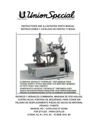
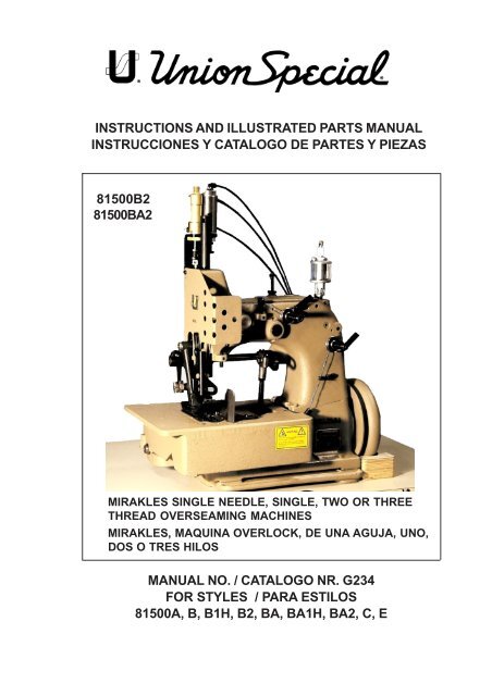
INSTRUCTIONS AND ILLUSTRATED PARTS MANUAL<br />
INSTRUCCIONES Y CATALOGO DE PARTES Y PIEZAS<br />
<strong>81500</strong>B2<br />
<strong>81500</strong>BA2<br />
MIRAKLES SINGLE NEEDLE, SINGLE, TWO OR THREE<br />
THREAD OVERSEAMING MACHINES<br />
MIRAKLES, MAQUINA OVERLOCK, DE UNA AGUJA, UNO,<br />
DOS O TRES HILOS<br />
MANUAL NO. / CATALOGO NR. G234<br />
FOR STYLES / PARA ESTILOS<br />
<strong>81500</strong>A, B, B1H, B2, BA, BA1H, BA2, C, E
MANUAL NO. G234<br />
INSTRUCTIONS AND ILLUSTRATED PARTS LIST<br />
FOR <strong>81500</strong> SERIES MACHINES<br />
Fitfth Edition Copyright 2002<br />
by<br />
Union Special GmbH Rights Reserved in All<br />
Countries<br />
Printed in Germany<br />
CATALOGO Nº G234<br />
INSTRUCCIONES Y LISTA DE PARTES<br />
ILUSTRADAS MODELOS SERIE <strong>81500</strong><br />
Quinta Edición © 2002<br />
Union Special GmbH<br />
Derechos Reservados<br />
en todos los paises del mundo<br />
Impreso en Alemania<br />
PREFACE<br />
This catalog has been prepared to guide you while<br />
operating <strong>81500</strong> series machines and arranged to simplify<br />
ordering spare parts.<br />
INTRODUCCION<br />
Este manual fue preparado para guiar al usuario en la<br />
operación de máquinas de la serie <strong>81500</strong> y ayudar para<br />
simplificar la elaboración de los pedidos de repuestos.<br />
This catalog explains in detail the proper settings for<br />
operation of the machines. Illustrations are used to show<br />
the adjustments and reference letters are used to point<br />
out specific items discussed.<br />
Careful attention to the instructions and cautions for<br />
operating and adjusting these machines will enable you<br />
to maintain the superior performance and reliability<br />
designed and built into every Union Special bag sewing<br />
machine.<br />
Adjustments and cautions are presented in sequence so<br />
that a logical progression is accomplished. Some<br />
adjustments performed out of sequence may have an<br />
adverse effect on the function of the other related parts.<br />
This manual has been comprised on the basis of available<br />
information. Changes in design and / or improvements<br />
may incorporate a slight modification of configuration in<br />
illustrations or cautions.<br />
On the following pages will be found illustrations and<br />
terminology used in describing the instructions and the<br />
parts for your machine.<br />
In addition to the instructions and to the mandatory rules<br />
and regulations for accident prevention and environmental<br />
protection in the country and place of use of the machine<br />
/ unit, the generally recognized technical rules for safe<br />
and proper working must also be observed.<br />
The instructions are to be supplemented by the respective<br />
national rules and regulations for accident prevention and<br />
environmental protection.<br />
Este manual explica detalladamente los ajustes para la<br />
operación de la máquina. Las ilustraciones sirven para<br />
demostrar los ajustes y las letras en referencia indican<br />
los puntos específicos discutidos.<br />
Una cuidadosa atención a las instrucciones y las<br />
precauciones operando y ajustando estas máquinas le<br />
va a permitir mantener el mejor funcionamiento y la<br />
confiabilidad que caracteriza las máquinas cosedoras<br />
de sacos de Union Special.<br />
Los ajustes y precauciones son presentados en<br />
secuencia para que se consiga una progresión lógica.<br />
La ejecución de algunos ajustes fuera de la secuencia<br />
puede causar un efecto adverso para el funcionamiento<br />
de otras partes relacionadas.<br />
Este manual se comprende a base de la información<br />
actual. Cambios en diseño y/o mejoras pueden significar<br />
leves modificaciones de la configuración de las<br />
ilustraciones o precauciones.<br />
En las páginas siguientes se encuentran ilustraciones<br />
y terminologías usadas en la descripción de las<br />
instrucciones y las piezas de la máquina.<br />
Adicionalmente a las instrucciones, las reglas y<br />
regulaciones obligatorias para prevenir accidentes y la<br />
protección ambiental del país y lugar donde se<br />
encuentra la máquina/unidad, hay que considerar las<br />
reglas técnicas para un trabajo seguro y adecuado.<br />
Las instrucciones hay que complementarlas con las<br />
respectivas reglas y regulaciones nacionales contra<br />
accidentes y protección del ambiente.<br />
2
SAFETY RULES<br />
REGLAS DE SEGURIDAD<br />
IDENTIFICATION OF MACHINES<br />
IDENTIFICACION DE LAS MAQUINAS<br />
APPLICATION OF THIS INSTRUCTION MANUAL<br />
APLICACION DE ESTE MANUAL DE INSTRUCCIONES<br />
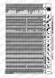
STYLES OF MACHINES<br />
ESTILOS DE MAQUINAS<br />
INSTALLATION<br />
INSTALACION<br />
LUBRICATING<br />
LUBRICACION<br />
NEEDLES<br />
AGUJAS<br />
THREADING DIAGRAM<br />
DIAGRAMAS DE ENHEBRADO<br />
OPERATING INSTRUCTIONS<br />
INSTRUCCIONES DE OPERACION<br />
MAINTENANCE<br />
MANTENIMIENTO<br />
INSTRUCTION FOR MECHANICS<br />
INSTRUCCIONES PARA LOS MECANICOS<br />
ORDERING WEAR AND SPARE PARTS<br />
INSTRUCCIONES PARA LOS PEDIDOS DE REPUESTOS<br />
VIEWS AND DESCRIPTION OF PARTS<br />
DIBUJOS Y DESCRIPCION DE LOS REPUESTOS<br />
BUSHINGS, SIGHT FEED OILER, OILERS<br />
BOCINAS Y PARTES DE LUBRICACION<br />
TABLE OF CONTENTS<br />
INDICE<br />
CLOTH PLATE, BASE PLATE, GUARDS AND MISCELLANEOUS COVERS<br />
TAPA Y BASE DE LA MAQUINA, GUARDAS Y OTRAS TAPAS<br />
THREAD TENSIONS AND THREAD GUIDE PARTS<br />
TENSIONES DE LOS HILOS Y PARTES DEL GUIA HILOS<br />
NEEDLE BAR, NEEDLE LEVER, CRANKSHAFT, HANDWHEEL<br />
BARRAS DE LA AGUJA, LEVANTADOR AGUJA, EJE PRINCIPAL, VOLANTE<br />
LOOPER DRIVE MECHANISM<br />
MECANISMO DE OPERACION DEL LOOPER<br />
UPPER AND LOWER FEED DRIVE MECHANISM<br />
MECANISMOS DEL TRANSPORTE SUPERIOR E INFERIOR<br />
PAGE / PAGINA<br />
4 - 5<br />
5<br />
5<br />
6 - 7<br />
8 – 11<br />
12 - 13<br />
13<br />
14 – 15<br />
16 – 18<br />
19<br />
20 - 31<br />
32<br />
33<br />
34 – 35<br />
36 – 37<br />
38 – 41<br />
42 – 43<br />
44 – 45<br />
46 - 47<br />
PRESSER BARS, PRESSER BAR SPRINGS AND PRESSER FOOT LIFTER LEVER<br />
BARRAS DEL PIE PRENSATELA, MUELLES PARA LAS BARRAS DEL PIE PRENSATELA Y LEVANTADOR DEL PIE<br />
PRENSATELA<br />
ELECTRO-PNEUMATIC PARTS KIT FOR UPPER FEED PRESSURE AND LIFTER FOR <strong>81500</strong>B1H, B2, BA1H, BA2 WITH<br />
ELECTRONIC DRIVE<br />
PIEZAS DEL SISTEMA ELECTRO NEUMATICO PARA PRESION DEL PIE SUPERIOR Y PARA LEVANTAR EL PIE PRENSA<br />
TELA PARA <strong>81500</strong>B1H, B2, BA1H, BA2 , CON MOTOR ELECTRONICO<br />
CONTROL FOR ELECTRO-PNEUMATIC HOT THREAD CHAIN CUTTER FOR <strong>81500</strong>B1H, BA1H<br />
CONTROL PARA EL SISTEMA ELECTRO NEUMATICO CORTADOR CALIENTE DE CADENETA PARA <strong>81500</strong>B1H, BA1H<br />
ELECTRO-PNEUMATIC HOT THREAD CHAIN CUTTER FOR <strong>81500</strong>B1H, BA1H<br />
SISTEMA ELECTRO NEUMATICO CORTADOR CALIENTE DE CADENETA PARA <strong>81500</strong>B1H, BA1H<br />
SEWING PARTS; STYLES <strong>81500</strong>A, B, B1H, B2, BA, BA1H, BA2 AND <strong>81500</strong>C<br />
PIEZAS DE FORMACION DE COSTURA, MODELOS <strong>81500</strong>A, B, B1H, B2, BA, BAH1, BA2 Y <strong>81500</strong>C<br />
SEWING PARTS, STYLE <strong>81500</strong>E<br />
PIEZAS DE FORMACION DE COSTURA, MODELO <strong>81500</strong>E<br />
ACCESSORIES<br />
ACCESORIOS<br />
NUMERICAL INDEX OF PARTS<br />
INDICE NUMERICO DE PARTES<br />
48 - 49<br />
50 - 51<br />
52 - 55<br />
56 - 57<br />
58 - 59<br />
60 - 61<br />
63 - 64<br />
65 - 66<br />
3
SAFETY RULES<br />
1. Before putting the machines described in this manual<br />
into service, carefully read the instructions. The starting<br />
of each machine is only permitted after taking notice of<br />
the instructions and by qualified operators.<br />
IMPORTANT! Before putting the machine into service,<br />
also read the safety rules and instructions from the<br />
motor supplier.<br />
2. Observe the national safety rules valid for your country.<br />
3. The sewing machines described in this instruction manual<br />
are prohibited from being put into service until it has<br />
been ascertained that the sewing units which these<br />
sewing machines will be built into, have conformed with<br />
the provisions of EC Machinery Directive 98/37/EC,<br />
Annex II B.<br />
Each machine is only allowed to be used as foreseen.<br />
The foreseen use of the particular machine is described<br />
in paragraph "STYLES OF MACHINES" of this instruction<br />
manual. Another use, going beyond the description, is<br />
not as foreseen.<br />
4. All safety devices must be in position when the machine<br />
is ready for work or in operation. Operation of the<br />
machine without the appertaining safety devices is<br />
prohibited.<br />
5. Wear safety glasses.<br />
6. In case of machine conversions and changes all valid<br />
safety rules must be considered. Conversions and<br />
changes are made at your own risk.<br />
REGLAS DE SEGURIDAD<br />
1. Antes de poner en marcha las máquinas descritas en<br />
este manual, hay que leer cuidadosamente las instrucciones.<br />
El arranque de cada máquina solamente<br />
se permite después de haber leído las instrucciones y<br />
debe ser realizado por personal calificado.<br />
IMPORTANTE! Antes de poner la máquina a operar,<br />
también hay que leer las reglas de seguridad y las<br />
instrucciones del fabricante del motor.<br />
2. Observe las reglas nacionales de seguridad que<br />
rigen para su país.<br />
3. No se puede poner en marcha la máquina descrita en<br />
este manual hasta que se confirme que la unidad de<br />
coser esta conforme con el reglamento del Directivo<br />
de las Máquinas de la Comunidad Europea 98/37/EC,<br />
Anexo II B.<br />
La máquina solamente se puede utilizar para su uso<br />
previsto. El uso previsto esta descrito en el capitulo<br />
ESTILO DE MAQUINAS de este manual de instrucciones.<br />
Otro uso, diferente de la descripción, no esta<br />
previsto.<br />
4. Todos los dispositivos de seguridad tienen que estar<br />
en su sitio cuando la máquina este lista para trabajar<br />
u operando. La operación de la máquina sin los<br />
dispositivos de seguridad esta prohibida.<br />
5. Utilice lentes de seguridad.<br />
6. En el caso de una modificación de la máquina hay que<br />
tomar en cuenta las reglas de seguridad. Modificaciones<br />
y cambios corren por su riesgo.<br />
7. The warning hints in the instructions are marked with<br />
one of these two symbols.<br />
7. Las advertencias en el manual de instrucciones están<br />
marcadas con las siguientes señales de aviso:<br />
8. When doing the following the machine has to be<br />
disconnected from the power supply by turning off<br />
the main switch or by pulling out the main plug.<br />
8.1 When threading needle(s), looper,<br />
spreader etc.<br />
8.2 When replacing any parts such as<br />
needle(s), presser foot, throat plate,<br />
looper, spreader, feed dog, needle guard,<br />
folder, fabric guide etc.<br />
8.3 When leaving the workplace and when<br />
the work place is unattended.<br />
8.4 When doing maintenance work.<br />
8.5 When using clutch motors with or without<br />
actuation lock, wait until motor is stopped<br />
totally.<br />
8. Para las siguientes maniobras hay que desconectar<br />
la máquina del suministro eléctrico desconectando el<br />
enchufe principal:<br />
8.1 Enhebrando agujas, looper y spreaders.<br />
8.2 Reemplazando piezas como agujas, pie prensa<br />
tela, plancha de aguja, looper, spreader, dientes<br />
de arrastre, guarda aguja, dobladilladores, guía<br />
tela, cuchillas, etc.<br />
8.3 Cuando salga de su puesto de trabajo y no se<br />
encuentre alguien para atender la máquina.<br />
8.4 Durante trabajos de mantenimiento.<br />
8.5 Utilizando motores de embrague sin freno, tiene<br />
que esperar que el motor pare completamente.<br />
4
9. Maintenance, repair and conversion work (see item 8)<br />
must be done only by trained technicians ors pecial<br />
skilled personnel under condsideration of the instructions.<br />
Only genuine spare parts approved by UNION SPECIAL<br />
have to be used for repairs. These parts are designed<br />
specifically for your machine and manufactured with<br />
utmost precision to assure long lasting service.<br />
10. Any work on the electrical equipment must be done by an<br />
electrician or under direction and supervision of special<br />
skilled personnel.<br />
11. Work on parts and equipment under electrical power is<br />
not permitted. Permissible exceptions are described in<br />
the applicable section of standard sheet EN 50 110 / VDE<br />
0105.<br />
12. Before doing maintenance and repair work on the<br />
pneumatic equipment, the machine has to be disconnected<br />
from the compressed air supply. In case of existing<br />
residual air pressure after disconnecting from compressed<br />
air supply (e.g. pneumatic equipment with air tank), the<br />
pressure has to be removed by bleeding. Exceptions are<br />
only allowed for adjusting work and function checks done<br />
by special skilled personnel.<br />
9. Mantenimiento, reparaciones y trabajos de conversión<br />
(véase No. 8) solamente pueden ser efectuados por<br />
técnicos entrenados o personal especializado bajo<br />
consideración de las instrucciones.<br />
Solamente repuestos originales y aprobados por Union<br />
Special pueden ser utilizados para reparaciones.<br />
Estos repuestos han sido diseñados específicamente<br />
para estas máquinas, con precisión y para asegurar<br />
su máxima vida útil.<br />
10. Cualquier trabajo con el equipo eléctrico tiene que ser<br />
ejecutado por un electricista o bajo la supervisión de<br />
personal especialmente entrenado.<br />
11. No esta permitido trabajar en piezas y equipos con la<br />
electricidad conectada. Excepciones permitidas están<br />
descritas en EN 50110 / VDE 0105.<br />
12. Antes de hacer mantenimiento o reparaciones del<br />
equipo neumático, hay que desconectar la máquina<br />
de la alimentación del aire comprimido. En el caso<br />
que exista una presión de aire residual después de<br />
desconectar la máquina (por ejemplo equipos con<br />
tanques de aire), la presión tiene que ser eliminada<br />
abriendo las válvulas. Excepciones están solamente<br />
permitidas para trabajos de ajuste y revisión de<br />
funciones por personal especialmente entrenado.<br />
IDENTIFICATION OF MACHINES<br />
Each UNION SPECIAL <strong>81500</strong> series machine is identified<br />
by a style number, which is stamped on the style plate affixed<br />
to the right front of machine. Serial number is stamped into<br />
bed casting at the right front base of machine.<br />
IDENTIFICACION DE LAS MAQUINAS<br />
Cada máquina UNION SPECIAL <strong>81500</strong> está identificada por<br />
un número de estilo, el cual está estampado en la placa fijada<br />
a la máquina. El número de serial está troquelado en la carcasa<br />
de la máquina.<br />
APPLICATION OF THIS INSTRUCTION MANUAL<br />
NOTE: Instructions stating direction or location such as right<br />
left, front or rear of machine, are given relative to<br />
operator’s position at the machine, unless otherwise<br />
noted.<br />
CAUTION!<br />
The handwheel pulley rotates clockwise, in operating<br />
direction, when viewed from the right end of machine.<br />
Before putting into service check the direction<br />
of rotation. Breakage may occur when the<br />
direction of rotation is wrong.<br />
APLICACIONES DE ESTE MANUAL DE INSTRUCCIONES<br />
NOTA: Instrucciones que se refieren a direcciones y<br />
posiciones como derecho, izquierdo, adelante o atrás<br />
se entienden desde el punto de vista de un operador<br />
sentado enfrente de la máquina, si no está notificado<br />
de una manera diferente.<br />
El manubrio del volante gira en sentido del reloj, en su<br />
dirección de operación, cuando es visto desde la par<br />
te derecha del final de la máquina.<br />
PRECAUCION: Revise antes de poner la máquina en<br />
marcha el sentido de la rotación. El<br />
sentido de rotación equivocado puede<br />
causar roturas.<br />
5
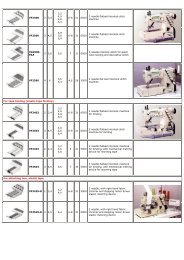
STYLES OF MACHINES<br />
„MIRAKLES“ single needle, single two and three thread<br />
overseamers with 71 mm (2 51/64 in.) needle throw. Manual<br />
lubrication.<br />
<strong>81500</strong>A: Two thread machine. For even matched seaming<br />
of heavy bag fabrics made from jute. Perfect start of seam.<br />
Uniform, neat seam.<br />
Plain feed with only swinging upper feed.<br />
Teeth cut 5 mm (5 teeth per inch).<br />
Seam specification 502/SSa-1.<br />
Standard seam width 19 mm (3/4 in.).<br />
Parts for 10, 12 and 15 mm (25/64, 15/32 and 19/32 in.)<br />
seam width come with the machine.<br />
<strong>Sewing</strong> capacity:<br />
At 19 mm (3/4 in.) seam width up to 16 mm (5/8 in.)<br />
At 15 mm (19/32 in.) seam width up to 19 mm (3/4 in.)<br />
At 12 mm (15/32 in.) seam width up to 21 mm (13/16 in.)<br />
At 10 mm (25/64 in.) seam width up to 22 mm (7/8 in.)<br />
Standard recommended needle type 9859G<br />
430/172. **<br />
Stitch range 6 to 13 mm (2 to 4 SPI). Standard setting 10<br />
mm (2 1/2 SPI).<br />
Working dia. of handwheel pulley 150 mm (5 29/32 in.).<br />
Speed up to 1400 stitches per minute, depending on fabric<br />
and sewing operation.<br />
Recommended operating speed 1200 stitches per minute.<br />
Equivalent continuous A-weighted sound pressure level<br />
on work stations at recommended operating speed: 84<br />
dB(A)*<br />
Weight net: 36 kg<br />
ESTILOS DE MAQUINAS:<br />
„MIRAKLES“ máquina overlock de una aguja, uno, dos o tres<br />
hilos, con un recorrido de la barra de aguja de 71 mm. Lubricación<br />
manual.<br />
<strong>81500</strong>A: Máquina de dos hilos. Para emparejar piezas sueltas en<br />
sacos de yute. Comienzo perfecto de la costura. Costura limpia,<br />
uniforme y pareja.<br />
Costura simple con alimentador superior solamente oscilando.<br />
Distancia entre dientes: 5 mm<br />
Especificación de costura 502/Ssa-a<br />
Ancho de costura estándar 19 mm<br />
Partes para 10, 12 y 15 mm vienen con la máquina.<br />
Capacidad de costura:<br />
Ancho de costura 19 mm: hasta 16 mm<br />
Ancho de costura 15 mm: hasta 19 mm<br />
Ancho de costura 12 mm: hasta 21 mm<br />
Ancho de costura 10 mm: hasta 22 mm<br />
Aguja normal recomendada: 9859G430/172. **<br />
Rango de puntada 6 a 13 mm. Ajuste de fabrica 10 mm.<br />
Diámetro efectivo del volante 150 mm.<br />
Velocidad de hasta 1400 Puntadas / min., dependiendo del material<br />
y la operación de costura.<br />
Velocidad de operación recomendada 1200 Puntadas / min.<br />
Nivel de ruido de la unidad referente al puesto de trabajo con la<br />
velocidad de operación recomendada 84dB (A)<br />
Peso, neto<br />
36 kgs<br />
<strong>81500</strong>B: Two thread machine. For even matched seaming<br />
of container bags made from woven polypropylene and<br />
simultaneously attaching regular, loosely woven belt bands<br />
with polypropylene sewing threads.<br />
Plain feed with synchronized upper feed.<br />
Teeth cut 5 mm (5 teeth per inch).<br />
Seam specification 502/SSa-1.<br />
Standard seam width 19 mm (3/4 in.).<br />
Parts for 10, 12 and 15 mm (25/64, 15/32 and 19/32 in.)<br />
seam width come with the machine.<br />
<strong>Sewing</strong> capacity:<br />
At 19 mm (3/4 in.) seam width up to 16 mm (5/8 in.)<br />
At 10 (25/64 in.), 12 (15/32 in.), and 15 mm (19/32 in.)<br />
seam width up to 19 mm (3/4 in.)<br />
Standard recommended needle type 9859G<br />
300/120 **.<br />
Stitch range 6 to 13 mm (2 to 4 SPI). Standard setting 10<br />
mm (2 1/2 SPI).<br />
Working dia. of handwheel pulley 150 mm (5 29/32 in.).<br />
* Noise measurement according to DIN 45635-48 /<br />
ISO 10 821<br />
** Please note page 13<br />
<strong>81500</strong>B: Máquina de dos hilos. Para emparejar piezas sueltas en<br />
sacos de polipropileno tejido y simultáneamente pegar correas<br />
suaves de material de polipropileno de alta tenacidad.<br />
Costura simple con alimentador superior sincronizado.<br />
Distancia entre dientes: 5 mm<br />
Especificación de costura 502/Ssa-a<br />
Ancho de costura standard 19 mm<br />
Partes para 10, 12 y 15 mm vienen con la máquina.<br />
Capacidad de costura:<br />
A 19 mm: hasta 16 mm.<br />
A 10, 12 y 15 mm: hasta 19 mm<br />
Aguja normal recomendada: 9859G430/172. **<br />
Rango de puntada 6 a 13 mm. Ajuste de fabrica 10 mm.<br />
Diámetro efectivo del volante 150 mm.<br />
*Medición de ruido, según norma DIN 45635-48 / ISO 10 821<br />
** Por favor, vea NOTA en página 13<br />
6
Speed up to 1400 stitches per minute, depending on<br />
fabric and sewing operation.<br />
Recommended operating speed 1200 stitches per<br />
minute.<br />
Equivalent continuous A-weighted sound pressure level<br />
on work stations at recommended operating speed: 81<br />
dB(A)*<br />
Weight net: 37 kg<br />
<strong>81500</strong>B1H: Same as <strong>81500</strong>B, but with built-in electropneumatically<br />
operated hot thread chain cutter. Electropneumatically<br />
operated presser foot and<br />
upper feed dog lifter.<br />
Pneumatic presser foot spring.<br />
Guides for filler cord from the top and / or from below<br />
for sealing the needle punctures of the left needle.<br />
<strong>81500</strong>B2: Same as 81300B1H, but without any thread<br />
chain cutter.<br />
<strong>81500</strong>BA: Same as <strong>81500</strong>B except for simultaneously<br />
attaching tightly woven, heavy belt bands.<br />
Standard recommended needle type 9859G430/172 **<br />
<strong>81500</strong>BA1H: Same as <strong>81500</strong>BA, but with built-in electropneumatically<br />
operated hot thread chain cutter. Electropneumatically<br />
operated presser foot and<br />
upper feed dog lifter.<br />
Pneumatic presser foot spring.<br />
Guides for filler cord from the top and / or from below<br />
for sealing the needle punctures of the left needle.<br />
<strong>81500</strong>BA2: Same as <strong>81500</strong>BA1H, but without any thread<br />
chain cutter.<br />
<strong>81500</strong>C: Three thread machine. Same as <strong>81500</strong> B, except<br />
three thread seam, stitch type 504.<br />
<strong>81500</strong>E: Single thread machine. For even matched, butted<br />
joining medium to heavy weight webs of fabric for finishing<br />
and dyeing purposes.<br />
Plain feed with synchronized upper feed. Alternating upper<br />
feed dog and presser foot. Teeth cut 5 mm (5 teeth per<br />
inch).<br />
Seam specification 501/ FSf-1.<br />
Seam width 19 mm (3/4 in.). Width of abutted seam<br />
35 mm (1 3/8 in.).<br />
<strong>Sewing</strong> capacity 13 mm (33/64 in.).<br />
Standard recommended needle type 9859G300/120 **<br />
Stitch range 6 to 13 mm (2 to 4 SPI).<br />
Standard setting 10 mm (2 1/2 SPI).<br />
Working dia. of handwheel pulley 150 mm (5 29/32 in.).<br />
Speed up to 1400 stitches per minute, depending on fabric<br />
and sewing operation.<br />
Recommended operating speed 1200 stitches per minute.<br />
Equivalent continuous A-weighted sound pressure level on<br />
work stations at recommended operating speed: 81 dB(A)*<br />
Weight net: 37 kg.<br />
* Noise measurement according to DIN 45635-48 /<br />
ISO 10 821<br />
Velocidad de hasta 1400 Puntadas / min., dependiendo del<br />
material y la operación de costura.<br />
Velocidad de operación recomendada 1200 Puntadas / min.<br />
Nivel de ruido de la unidad referente al puesto de trabajo con<br />
la velocidad de operación recomendada81dB (A)<br />
Peso, neto<br />
37 kg.<br />
<strong>81500</strong>B1H: Igual a la <strong>81500</strong>B, pero con cortador electroneumático<br />
caliente de cadeneta y pie prensatelas y levantador<br />
del diente superior activados electroneumáticamente.<br />
Pie prensatelas con presión neumática por pistón.<br />
La máquina está equipada con una guía superior e inferior<br />
de los cordeles para sellar las perforaciones de las agujas<br />
desde arriba y/o desde abajo de la aguja izquierda.<br />
<strong>81500</strong>B2: Igual a la <strong>81500</strong>B1H, pero sin ningún cortador de<br />
cadeneta.<br />
<strong>81500</strong>BA: Igual a la <strong>81500</strong>B, excepto que simultáneamente<br />
se pueden pegar correas tejidas de rafia.<br />
Tipo de aguja recomendada 9859G430/172 **<br />
<strong>81500</strong>BA1H: Igual a la <strong>81500</strong>BA, pero con cortador electroneumático<br />
caliente de cadeneta y pie prensatelas y levantador<br />
del diente superior operados electroneumáticamente.<br />
Pie prensatelas con presión neumática por pistón.<br />
La máquina está equipada con una guía superior e inferior<br />
de los cordeles para sellar las perforaciones de las agujas<br />
desde arriba y/o desde abajo de la aguja izquierda.<br />
<strong>81500</strong>BA2: Igual a la <strong>81500</strong>BA1H, pero sin ningún cortador<br />
de cadeneta.<br />
<strong>81500</strong>C: Máquina de 3 hilos, Igual a la <strong>81500</strong> B, pero con 3<br />
hilos. Tipo de costura 504.<br />
<strong>81500</strong>E: Máquina de un solo hilo, para coser tejidos medianos<br />
y pesados sin desplazamiento y pegado a tope, para<br />
acabado posterior de tintorería.<br />
Transporte alimentador simple con diente superior sincronizado.<br />
Diente superior alternando con el pie prensatelas. Distancia<br />
entre dientes: 5 mm<br />
Especificación de costura 501/ FSf-1.<br />
Ancho de costura 19 mm: hasta 35 mm.<br />
Capacidad de costura: 13 mm.<br />
Aguja normal recomendada 9859G300/120 **<br />
Rango de puntada 6 a 13 mm.<br />
Ajuste de fabrica 10 mm.<br />
Diámetro efectivo del volante 150 mm.<br />
Velocidad de hasta 1400 Puntadas / min., dependiendo del<br />
material y la operación de costura.<br />
Velocidad de operación recomendada 1200 Puntadas / min.<br />
Nivel de ruido de la unidad referente al puesto de trabajo con<br />
la velocidad de operación recomendada81dB (A)<br />
Peso, neto<br />
37 kg.<br />
* Medición de ruido, según norma DIN 45635-48 / ISO 10 821<br />
** Por favor, vea NOTA en página 13<br />
** Please note page 13<br />
Use UNION SPECIAL sewing tables for the described sewing<br />
machines. UNION SPECIAL sewing tables complete the<br />
particular sewing machine to a sewing unit and guarantee<br />
safe operation as well as the indicated data of the sound<br />
pressure level generated by the sewing unit.<br />
Utilize montajes de UNION SPECIAL para las máquinas descritas.<br />
Mesas y pedestales de UNION SPECIAL complementan<br />
las máquinas de coser a una unidad de coser y garantizan<br />
una operación segura y los niveles de ruido.<br />
7
INSTALLATION<br />
INSTALACION<br />
8
INSTALLATION (continued)<br />
INSTALACION (Continuación)<br />
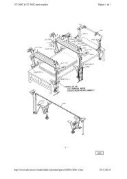
1. Unpack the sewing machine and the accessories.<br />
2. Mount the base plate (A, Fig. 1) with four screws, nuts<br />
and washers (B) in the provided holes on the table board.<br />
3. Place the sewing machine on the base plate so that the<br />
roll pin (C) in the base plate engages with the right rear<br />
hole in the machine base.<br />
4. Fasten the sewing machine with the two T-screws (D) on<br />
the base plate.<br />
5. Place the V-belt, supplied with the sewing table, on the<br />
handwheel pulley .<br />
6. Assemble the handwheel pulley (E) with three<br />
countersunk screws (F) to the sewing machine. Pin (G)<br />
must engage with the hole in hub (H).<br />
1. Desempaque la máquina y los accesorios.<br />
2. Monte la placa de base (A, Fig. 1) con los 4 tornillos,<br />
tuercas y arandelas (B) en los huecos previstos en la<br />
tabla de la mesa.<br />
3. Coloque la maquina sobre la base, de manera que el<br />
pasador de regulación (C) en la placa base, encaje en<br />
el hueco derecho trasero de la base de la máquina.<br />
4. Asegure la máquina de coser con los 2 tornillos T (D)<br />
en la placa de base.<br />
5. Coloque la correa en forma de V, en la rueda del volante.<br />
6. Monte el volante (E) con los 3 tornillos remache (F) a<br />
la máquina de coser. El pasador (G) debe encajar en<br />
el hueco de la parte central del volante (H).<br />
7. Screw in needle bar guard (J).<br />
8. Screw in sight feed oiler (K).<br />
9. Align the handwheel belt guard (L) with the V-belt slot<br />
(M) in the table board and with the handwheel pulley and<br />
fasten it with two wood screws (N) on the table board.<br />
10. Dismount motor belt guard. Place the V-belt around the<br />
motor pulley and slue the motor to tense the belt. The<br />
tension on the V-belt is correct, when with moderate<br />
finger pressure it will deflect approx. 10 mm (3/8 in.)<br />
midway between handwheel pulley on the sewing<br />
machine and motor pulley (see Fig. 2).<br />
Remount motor belt guard.<br />
7. Atornille el protector de la barra de aguja (J).<br />
8. Asegure la aceitera (K).<br />
9. Alinie el guarda correa del volante (L) con la perforación<br />
para la correa en la mesa (M) y con la rueda del<br />
volante y sujetelo con los 2 tornillos para madera (N)<br />
a la mesa.<br />
10. Desmonte el guarda correa del motor. Coloque la correa<br />
en V alrededor del volante y ajuste el motor para<br />
tensar la correa. La tensión de la correa en V será la<br />
correcta cuando ejerciendo presión moderada con el<br />
dedo ceda en aprox. 10mm (3/8 pulgada) en la mitad<br />
entre la rueda del volante en la maquina de coser y la<br />
rueda del motor (Ver Fig. 2).<br />
Coloque nuevamente el guarda correa del motor.<br />
9
INSTALLATION (continued)<br />
11. Hook the lifter chain to the lifter lever of the sewing<br />
machine and to the small treadle on the sewing table.<br />
12. Assemble the thread stand and mount the thread stand<br />
base with three wood screws on the right rear corner of<br />
the table board.<br />
13. Before being put into service note the specified service<br />
voltage and frequency of the motor. Check if the mains<br />
voltage and frequency at site correspond with the factory<br />
specified service voltage and frequency.<br />
14. Check the direction of rotation. The handwheel pulley<br />
must rotate clockwise (to the right), when viewed from<br />
the right end of the machine.<br />
Switch on the motor. Only shortly and very slightly depress<br />
the motor treadle and check the direction of rotation.<br />
Immediately release the treadle. Switch off and wait<br />
until the motor has stopped.<br />
INSTALACION (Continuación)<br />
11. Enganche la cadena a la palanca levantadora de la<br />
máquina de coser y al pequeño pedal en la mesa de la<br />
máquina de coser.<br />
12. Asegure la base del porta conos con tres tornillos al lado<br />
derecho de la mesa de la máquina de coser y monte el<br />
porta conos.<br />
13. Antes de comenzar a utilizar la máquina, verifique que<br />
el voltaje y la frecuencia del motor coinciden con la instalada<br />
en el lugar donde operará la máquina.<br />
14. Verifique la dirección de rotación. El volante debe girar<br />
en dirección del reloj (a la derecha), cuando es visto<br />
desde la parte derecha de la máquina.<br />
Encienda el motor. Presione ligeramente el pedal y<br />
chequee la dirección de rotación. Suéltelo inmediatamente.<br />
Apague el motor y espere hasta que se detenga totalmente.<br />
CAUTION!<br />
In case the direction of rotation has to be<br />
changed, the reversing of the polarity is only<br />
allowed to be done by a skilled electrician.<br />
PRECAUCION! En el caso que la dirección de rotación<br />
deba ser cambiada, la reversión de la polaridad<br />
debe ser realizada por un electricista<br />
calificado.<br />
11
LUBRICATING<br />
Turn off main power switch before<br />
lubricating! When using clutch motors with<br />
or without actuation lock wait until motor<br />
has completely stopped.<br />
LUBRICACION<br />
Antes de lubricar, apague el interruptor<br />
principal. Con un motor de embrague<br />
sin freno espere hasta que el motor se<br />
detenga completamente!<br />
12
LUBRICATING (continued)<br />
PREPARING FOR OPERATING<br />
Before operating a new machine for the first time, the sight<br />
feed oiler has to be adjusted. All lubrication points, indicated<br />
on the oiling diagram (Fig. 4), have to be oiled.<br />
For adjusting fill the sight feed oiler half-way with oil and<br />
turn the metering pin (A, Fig. 4) a little bit out and then turn<br />
it in, until there will flow two to three drops of oil per minute.<br />
This can be checked on the sight glass (B). Secure the setting<br />
of the metering pin with lock nut (C). Fill the oiler.<br />
Repeat the oiling of a new machine after 10 minutes of<br />
operation!<br />
When the machine is out of operation, the oil flow can be<br />
stopped by tilting lever (D).<br />
IMPORTANT!The oil flow has to be switched on again<br />
before operating the machine.<br />
For lubrication we recommend "Mobil Oil DTE Medium" or<br />
equivalent, which can be purchased from UNION SPECIAL<br />
in 1/2 liter containers under part number G28604L or in 5<br />
liter containers under part number G28604L5.<br />
NEEDLES<br />
Each needle has both a type and size number. The type<br />
number denotes the kind of shank, point, length, groove,<br />
finish and other details. The size number, stamped on the<br />
needle shank, denotes the largest diameter of the blade,<br />
measured midway between the shank and the eye.<br />
Collectively, type and size number represent the complete<br />
symbol, which is given on the label of all needle packs and<br />
sold by UNION SPECIAL.<br />
LUBRICACION (Continuación)<br />
INSTRUCCIONES DE OPERACION<br />
Antes de poner en marcha una nueva máquina por la primera<br />
vez, hay que fijar y ajustar el engrasador cuentagotas. Lubrique<br />
todos los puntos indicados en el diagrama de lubricación (Fig.<br />
4).<br />
Llene el engrasador cuentagotas hasta la mitad con aceite y<br />
ajuste girando el pasador de la regulación (A, Fig. 4) en tal<br />
manera que suministre aproximadamente dos gotas de aceite<br />
por minuto. Este ajuste se puede revisar a través del vidrio (B).<br />
Asegure la posición del pasador de la regulación con la<br />
contratuerca (C). Llene el engrasador cuentagotas con aceite.<br />
Para máquinas nuevas, repita la lubricación después de diez<br />
minutos de operación.<br />
Si la máquina no está operando se puede parar el flujo del aceite<br />
doblando la palanca (D) del engrasador cuentagotas.<br />
Nota: El flujo de aceite tiene que ser restablecido antes de<br />
operar la máquina otra vez.<br />
Para la lubricación recomendamos „Mobil Oil DTE Medium“ o<br />
un aceite equivalente, que se puede pedir a UNION SPECIAL<br />
en contenedores de ½ litro bajo el número de referencia G28604L<br />
y en contenedores de 5 litros bajo el número de referencia<br />
G28604L5.<br />
AGUJAS<br />
Cada aguja tiene un número de sistema y un número del grosor.<br />
El número del sistema se refiere al tipo del cabo, la punta, el<br />
largo, la ranura, acabado y otros detalles. El número del grosor,<br />
troquelado en el cabo, indica el grosor máximo de la caña,<br />
medido en la mitad de la distancia entre cabo y ojo de la aguja.<br />
El número del sistema y del grosor dan la descripción completa,<br />
que se encuentra en todos los empaques de agujas vendidas<br />
por UNION SPECIAL.<br />
TYPE AND DESCRIPTION<br />
9859G Round shank with seat, round point (size 300/120)<br />
or rounded square point (size 430/172), single groove,<br />
spotted, ball eye, chromium plated.<br />
Sizes available: 300/120, 430/172.<br />
NEEDLE ORDERING<br />
To have needle orders promptly and accurately filled, an<br />
empty package, a sample needle or the type and size number<br />
should be forwarded. Use the description on the label.<br />
The standard needle for styles <strong>81500</strong>B, B1H, B2,<br />
<strong>81500</strong>C and <strong>81500</strong>E is 9859G300/120*.<br />
The standard needle for styles <strong>81500</strong>A, BA, BA1H, BA2<br />
is 9859G430/172.*<br />
A complete order should read as follows:<br />
100 needles, type 9859G, size 300/120*.<br />
* Please note, shorter needles 9853GA300/120 and<br />
9853GA430/172 are also available.<br />
TIPO Y DESCRIPCION<br />
9859G Cabo redondo con superificie plana para asentar la aguja,<br />
punta redonda (Tamaño 300/120) o punta cuadrada redondeada<br />
(Tamaño 430/172), ranura simple,rebajo,ojo reforzado,<br />
cromado.<br />
Tamaños disponibles: 300/120, 430/172.<br />
PEDIDO DE AGUJAS<br />
Para garantizar un despacho correcto y rápido les sugerimos<br />
enviarnos el empaque vacío de las agujas ó una aguja de<br />
muestra ó indicar el sistema con el grosor. Utilíze la descripción<br />
de la etiqueta en el empaque de la aguja.<br />
La aguja normal recomendada para los estilos <strong>81500</strong>B, B1H,<br />
B2, <strong>81500</strong>C y <strong>81500</strong>E es la 9859G300/120*.<br />
La aguja normal recomendada para los estilos <strong>81500</strong>A, BA,<br />
BA1H, BA2 es la 9859G430/172.*<br />
Un pedido completo de agujas sería por ejemplo:<br />
100 agujas, tipo 9859G, Grosor 300/120.*<br />
*Por favor, tome en cuenta que tambien tenemos disponibles<br />
agujas mas cortas 9853GA300/120 y 9853GA430/172.<br />
13
THREADING DIAGRAM<br />
DIAGRAMA DE ENHEBRADO<br />
CAUTION!<br />
Turn off main power switch before<br />
threading! When using clutch motors with<br />
or without actuation lock wait until the<br />
motor has completely stopped!<br />
PRECAUCION! Apague el motor principal antes de<br />
enhebrar!. Cuando utilice motor con clutch<br />
debe esperar hasta que el mismo se<br />
detenga totalmente!.<br />
14
THREADING DIAGRAM<br />
DIAGRAMA DE ENHEBRADO<br />
CAUTION!<br />
Turn off main power switch before<br />
threading! When using clutch motors with<br />
or without actuation lock wait until the<br />
motor has completely stopped!<br />
PRECAUCION! Apague el motor principal antes de<br />
enhebrar!. Cuando utilice motor con clutch<br />
debe esperar hasta que el mismo se<br />
detenga totalmente!.<br />
15
OPERATING INSTRUCTIONS<br />
THREADING<br />
INSTRUCCIONES DE OPERACION<br />
DIAGRAMA DE ENHEBRADO<br />
CAUTION!<br />
Turn off main power switch before<br />
threading! When using clutch motors<br />
with or without actuation lock wait until<br />
the motor has stopped!<br />
PRECAUCION! Apague el motor principal antes de<br />
enhebrar!. Cuando utilice motor con clutch<br />
debe esperar hasta que el mismo se<br />
detenga totalmente!.<br />
Styles <strong>81500</strong>A, B, B1H, B2, BA, BA1H, BA2 and <strong>81500</strong>E<br />
are threaded as shown in Fig. 5.<br />
Style <strong>81500</strong>C is threaded as shown in Fig. 5 A.<br />
For threading the needle turn handwheel in operating<br />
direction until the needle is in the upmost position.<br />
For looper threading open the hinge plate by lifting locking<br />
bolt knob (A, Figs. 5 and 5 A).<br />
Reclose hinge plate after threading.<br />
OPERATING<br />
1. Switch on main power switch.<br />
2. Without lifting the presser foot, place the fabric to<br />
be sewn as close as possible in front of the needle<br />
and to the right on the edge guide.<br />
Para enhebrar estilos <strong>81500</strong>A, B, B1H, B2, BA, BA1H,<br />
BA2 y <strong>81500</strong>E, por favor vea diagrama en Fig. 5.<br />
Para enhebrar estilo <strong>81500</strong>C, por favor vea diagrama en<br />
Fig. 5 A.<br />
Para enhebrar la aguja gire el volante en sentido de operación<br />
hasta que la aguja se encuentre en su posición<br />
superior. Para enhebrar el looper abra la tapa delantera<br />
levantando el tornillo de manivela (A, Figs.5 y 5A).<br />
Cierre la tapa delantera otra vez.<br />
OPERACION<br />
1. Active el interruptor principal.<br />
2. Ponga las telas lo más cercano posible delante de la aguja<br />
y a la derecha a la guía tope, sin levantar el pie prensatela.<br />
CAUTION!<br />
Remove the foot from the motor treadle,<br />
to avoid inadvertently starting of the<br />
machine, in case it is necessary to lift<br />
presser foot and upper feed dog for<br />
aligning the fabric to be sewn!<br />
PRECAUCION! Quite el pie del pedal del motor para no<br />
arrancar la máquina accidentalmente, si<br />
fuera necesario levante el pie prensatela y<br />
el transporte superior manualmente para<br />
guiar las telas.<br />
3. Depress the motor treadle. The machine sews.<br />
Guide the fabric to be sewn.<br />
3. Pise el pedal de motor hacia adelante. La máquina cose.<br />
Guíe las telas.<br />
CAUTION! Keep a security distance of approx. 100<br />
mm (4 in.) between hand and sewing<br />
needle when guiding the fabric to be<br />
sewn!<br />
4. Release the motor treadle. The machine stops.<br />
Cut the thread chain at the trailing edge of the fabric<br />
and remove the fabric from the machine.<br />
PRECAUCION! Mantenga una distancia de por lo menos<br />
100 mm entre la aguja y la mano mientras<br />
guíe las telas!<br />
4. Suelte el pedal del motor. La máquina se parará. Corte la<br />
cadeneta al final de las telas cosidas y quite los sobrantes<br />
de la superficie de la máquina.<br />
16
NEEDLE THREAD TAKE-UP<br />
Basically the needle thread take-up roller (B, Figs. 5 and<br />
5A), located left on the upper bed casting under the face<br />
cover, is set as low as possible.<br />
In case more needle thread should be pulled off for a bigger<br />
needle thread loop (depending on thread and fabric), raise<br />
the needle thread take-up roller accordingly.<br />
Fasten the needle thread guide (C, Figs. 5 and 5A), located<br />
on the top of the upper bed casting, approx. in the middle of<br />
its shank.<br />
THREAD TENSION<br />
Regulate the tension on the threads so that uniform stitches<br />
are produced.<br />
In general the tension applied to the needle thread is slightly<br />
higher than the tension applied to the looper thread(s).<br />
Turning the tension nuts clockwise increases the tension,<br />
turning counterclockwise decreases the tension.<br />
ALIMENTACION DEL HILO DE LA AGUJA<br />
Generalmente el rodillo del alimentador del hilo de la aguja<br />
(B, Figs. 5 y 5A), que está situado en la parte delantera<br />
izquierda del brazo debajo de la tapa frontal, debería estar<br />
fijado tan bajo como sea posible.<br />
En el caso que se necesite más hilo para crear un lazo de hilo<br />
más grande (dependiendo del hilo y tela) tiene que subir el<br />
rodillo adecuadamente.<br />
Fije el guía hilo (C, Fig. 5 y 5 A), que está situada en la parte<br />
delantera superior del brazo, aproximadamente en la mitad de<br />
su mango.<br />
TENSION DE LOS HILOS<br />
Regule la tensión de los hilos de tal manera que se logre una<br />
formación uniforme de la costura.<br />
Normalmente el hilo de la aguja tiene más tensión que el hilo<br />
del looper.<br />
Girar las tuercas del tensor en sentido de reloj aumenta la<br />
tensión, girar en sentido contra el reloj la disminuye.<br />
CHANGING THE NEEDLE<br />
CAUTION!<br />
Turn off main power switch before<br />
changing the needle! When using clutch<br />
motors with or without actuation lock wait<br />
until the motor has stopped!<br />
Turn the handwheel pulley in operating direction until the<br />
needle is in its upmost position.<br />
Unthread the eye of the needle to be changed.<br />
Loosen screw (D, Figs. 5 and 5A) for the needle and pull<br />
out the needle. Insert the shank of the new needle as far as<br />
it will go and with the long groove of the needle facing to the<br />
front (toward the operator). Tighten screw (D) on the seat of<br />
the needle shank and thread the needle eye.<br />
CAMBIO DE AGUJA<br />
PRECAUCION! Antes de cambiar la aguja, apague el interruptor<br />
principal de la máquina. Con un motor<br />
de embrague sin freno, espere hasta que<br />
el motor se detenga completamente!<br />
Gire el volante en sentido de operación hasta que la aguja se<br />
encuentre en su posición superior.<br />
Retire el hilo del ojo de la aguja.<br />
Suelte el tornillo fijador de la aguja (D, Fig. 5 y 5 A) y quite la<br />
aguja. Inserte la nueva aguja en tal manera que el cabo de la<br />
aguja toque el final de la barra de la aguja y la ranura de la<br />
aguja esté posicionada hacia adelante en dirección al operador.<br />
Apriete el tornillo (D) otra vez en la superficie plana para asentar<br />
la aguja y enhebre el hilo por el ojo de la aguja.<br />
EDGE GUIDE AND STITCH TONGUE<br />
CAUTION!<br />
Turn off main power switch before setting<br />
edge guide and stitch tongue and changing<br />
the seam width! When using clutch motors<br />
with or without actuation lock wait until<br />
the motor has stopped!<br />
Styles <strong>81500</strong>A, B, B1H, B2, BA, BA1H, BA2 and <strong>81500</strong>C,<br />
see Fig. 6.<br />
Style <strong>81500</strong>E, see Fig. 6 A.<br />
GUIA TOPE Y LENGUETA DE COSTURA:<br />
PRECAUCION! Antes de cambiar la guía tope y la lengüeta<br />
de costura, apague el interruptor principal<br />
de la máquina. Con un motor de embrague<br />
sin freno, espere hasta que el motor se<br />
detenga completamente!<br />
Para estilos <strong>81500</strong>A, B, B1H, B2, BA, BA1H, BA2 y <strong>81500</strong>C,<br />
favor ver Fig. 6.<br />
Para estilo <strong>81500</strong>E, vea Fig. 6 A.<br />
17
Set the edge guide (A, Figs. 6 and 6 A) laterally as close<br />
as possible to the presser foot, without contacting it. When<br />
loosening the two screws (B), the edge guide (A) can be<br />
moved laterally. Retighten screws.<br />
Ajuste la guía tope (A, Figs. 6 y 6A) tan cerca como sea<br />
posible al pie prensatelas, pero sin tocarlo. Cuando suelte los<br />
dos tornillos (B) la guía tope (A) podrá moverse lateralmente.<br />
Reajuste los tornillos de nuevo.<br />
Set the stitch tongue (C, Figs. 6 and 6 A) so that the rear<br />
part of the thread loop slides over the tongue onto the fabric,<br />
while the front part of the loop is retained until the needle<br />
securely has entered the loop. After loosening screws (D)<br />
the stitch tongue (C) can be moved to the front or to the<br />
rear. When moving the stitch tongue to the rear, the front<br />
part of the thread loop is retained longer. Retighten screws<br />
(D).<br />
On its travel the upper spreader or upper looper should not<br />
contact stitch tongue (C).<br />
ADJUSTABLE EDGE GUIDE<br />
Style <strong>81500</strong>E<br />
Set the adjustable edge guide (E, Fig. 6 A) so far to the left<br />
that the edges of the joined fabric webs are butted when<br />
opening the seam.<br />
Ajuste la lengüeta de costura (C, Figs. 6 y 6 A) , de manera tal<br />
que la parte trasera del lazo del hilo desliza sobre la lengüeta<br />
hacia el tejido, mientras la parte delantera del lazo del hilo<br />
queda retenida hasta que la aguja entra al lazo del hilo. Después<br />
de soltar los tornillos (D) la lengüeta de costura (C) podrá<br />
moverse hacia adelante o hacia atrás. Cuando la lengüeta<br />
de costura se mueva hacia atrás, la parte frontal del lazo<br />
del hilo quedará retenida por mas tiempo. Reajuste los tornillos<br />
(D) de nuevo.<br />
Durante el movimiento el spreader superior o el looper superior<br />
no deben tocar la lengüeta de costura (C).<br />
GUIA TOPE AJUSTABLE<br />
Estilo <strong>81500</strong>E<br />
Ponga la guía tope ajustable (E, Fig. 6 A) tanto hacia la izquierda<br />
como sea posible para que los bordes de las telas<br />
queden paralelos y uno frente al otro cuando se abra la costura.<br />
CHANGING THE SEAM WIDTH<br />
Styles <strong>81500</strong>A, B, B1H, B2, BA, BA1H, BA2 and <strong>81500</strong>C<br />
The machines are set at the factory to a seam width of 19<br />
mm (3/4 in.) Presser foot tongues for 10 mm (25/64 in.),<br />
12 mm 15/32 in.) and 15 mm (19/32 in.) are added to the<br />
machines.<br />
For changing the seam width remove the three screws (F,<br />
Fig. 6) and interchange the presser foot tongue (G) with<br />
the presser foot tongue for the required seam width. Fasten<br />
the tongue with the three screws (F).<br />
Set the edge guide (A) laterally as close as possible to the<br />
presser foot tongue without contacting it.<br />
Readjust the thread tension, if required.<br />
18<br />
AJUSTE DEL ANCHO DE LA COSTURA<br />
Estilos <strong>81500</strong>A, B, B1H, B2, BA, BA1H, BA2 y <strong>81500</strong>C<br />
Las máquinas han sido ajustadas en la fabrica con un ancho<br />
de costura de 19 mm. Lengüetas del pie prensatelas adicionales<br />
para 10, 12 y 15 mm vienen con la máquina.<br />
Para cambiar el ancho de la costura, remueve los tres tornillos<br />
(F, Fig. 6) y coloque la lengüeta del pie prensatelas (G)<br />
con el ancho deseado. Asegure la lengüeta nuevamente con<br />
los tres tornillos (F).<br />
Ajuste la guía tope (A) lateralmente lo mas cerca posible a la<br />
lengüeta pero sin tocarla.<br />
Reajuste la tensión de los hilos, en caso de ser necesario.
MAINTENANCE<br />
MANTENIMIENTO<br />
CAUTION!<br />
Turn off main power switch before doing<br />
maintenance works! When using clutch<br />
motors with or without actuation lock wait<br />
until the motor has stopped!<br />
PRECAUCION! Antes de efectuar cualquier trabajo de<br />
mantenimiento, apague el interruptor<br />
principal de la máquina. Con un motor<br />
de embrague sin freno, espere hasta que<br />
el motor se detenga completamente!<br />
LUBRICATING AND CLEANING<br />
The machines of class <strong>81500</strong> have to be cleaned and<br />
lubricated twice a day before morning and afternoon start<br />
on the lubrication points indicated on the oiling diagram<br />
(Fig. 4). The sight feed oiler has to be kept filled and should<br />
be adjusted so, that it feeds two to three drops of oil per<br />
minute. The oiler has to be refilled latest, when 2/3 of the<br />
oil are used up.<br />
Also refer to section LUBRICATING.<br />
LUBRICACION Y LIMPIEZA<br />
Las máquinas de la serie <strong>81500</strong> hay que limpiar dos veces<br />
al día – preferiblemente en la mañana y en la tarde antes de<br />
empezar la operación - y lubricar con aceite en los puntos<br />
indicados en el diagrama de lubricación (Fig. 4). Llene el<br />
engrasador cuentagotas hasta la mitad con aceite y ajuste<br />
girando el pasador de la regulación en tal manera que<br />
suministre aproximadamente dos a tres gotas de aceite por<br />
minuto. Hay que rellenar el engrasador cuentagotas con<br />
aceite cuando se hayan consumido 2/3 de su contenido.<br />
También refiérase a la sección LUBRICACION.<br />
19
INSTRUCTIONS FOR MECHANICS<br />
INSTRUCCIONES PARA MECANICOS<br />
Observe the SAFETY RULES when making<br />
adjustments!<br />
Before adjusting the machine remove the face cover and<br />
the finger guard left on the machine head, the upper feed<br />
dog, the presser foot, the cloth plate with hinge plate and<br />
throat plate, the feed dog, the throat plate support with<br />
front needle guard and the rear needle guard.<br />
Insert a new needle!<br />
Refer to paragraph CHANGING THE NEEDLE in section<br />
OPERATING INSTRUCTIONS.<br />
SETTING THE LOWER LOOPER<br />
1. Styles <strong>81500</strong>A, B, B1H, B2, BA, BA1H, BA2 and<br />
<strong>81500</strong>C<br />
The lower looper (A, Fig. 7) of these styles has two<br />
offset flats on its shank for adjusting the looper respectively<br />
the looper point with respect to the needle.<br />
Insert the lower looper (A) into the rear hole of looper<br />
lever (B). Now snug the set screw (C) at the back of<br />
the looper lever against the flat on the looper shank<br />
(E) so that the point of the lower looper passes as<br />
close as possible to the spot on the back of the needle<br />
(N), without deflecting it. Now tighten the second screw<br />
(D) firmly.<br />
Preste atención a las REGLAS DE SEGURI-<br />
DAD mientras realiza ajustes!<br />
Antes de realizar ajustes en la máquina, quite la tapa frontal y<br />
el protector de dedos, el diente alimentador superior, el pie<br />
prensatelas, la plancha de tela con la plancha articulada y la<br />
plancha de aguja, el diente alimentador, el soporte de la plancha<br />
de aguja y los guarda aguja delantero y trasero.<br />
Coloque una nueva aguja!<br />
Refiérase al parágrafo CAMBIO DE AGUJA en la sección INS-<br />
TRUCCIONES DE OPERACION.<br />
AJUSTE DEL LOOPER INFERIOR<br />
1. Estilos <strong>81500</strong>A, B, B1H, B2, BA, BA1H, BA2 y <strong>81500</strong>C<br />
El looper inferior (A, Fig. 7) en estos estilos de máquinas<br />
tienen dos superficies planas en su cuello para ajustar<br />
adecuadamente el looper con respecto a la aguja.<br />
Inserte el looper inferior (A) en el hueco posterior de la<br />
leva del looper (B). Sujete el tornillo de sujeción (C) en la<br />
parte trasera de la leva del looper contra la parte plana<br />
del cuello del looper (E) para que la punta del looper<br />
inferior pase lo mas cerca posible al rebajo en la parte<br />
trasera de la aguja (N) sin desviarla. Apriete el segundo<br />
tornillo (D) ahora.<br />
1.1. Rotate handwheel in operating direction until the<br />
needle just starts from its lowest position moving<br />
upward. In this position the distance between the point<br />
of the looper and the center of the needle should be<br />
12 mm (15/32 in.) (see Fig. 8).<br />
If adjustment is necessary loosen nut (G, Fig. 7) and<br />
move the ball stud (H) of ball joint (J) in the slot of<br />
looper lever (B) accordingly until the distance of 11<br />
mm (7/16 in.) is reached. Retighten nut (G).<br />
1.1 Gire el volante en sentido de operación hasta que la aguja<br />
quede en su posición mas baja antes de moverse hacia<br />
arriba. En este punto, la distancia entre la punta del<br />
looper y el centro de la aguja debe ser de 12 mm (Ver<br />
Fig. 8).<br />
De ser necesario algún ajuste adicional, suelte la tuerca<br />
(G, Fig. 7) y mueva el perno de bola (H) de la articulación<br />
esférica (J) en la ranura de la leva del looper (B)<br />
hasta que alcance una distancia de 11 mm.<br />
Apriete la tuerca (G) nuevamente.<br />
2. Style <strong>81500</strong>E<br />
The lower spreader (A, Fig. 7 A) of this style has only<br />
one seat on its shank.<br />
Insert the lower spreader (A, Fig. 7 A) into the rear<br />
hole of looper lever (B). Tighten screw (D) on the seat<br />
of the lower spreader shank, then tighten set screw<br />
(C).<br />
2. Estilo <strong>81500</strong>E<br />
El spreader inferior (A, Fig. 7 A) en este estilo de máquina<br />
tiene 1 sola superficie plana en su cuello.<br />
Inserte el spreader inferior (A, Fig. 7 A) en el hueco<br />
posterior de la leva del looper (B). Ajuste el tornillo (D)<br />
en la parte plana del cuello del spreader, luego apriete<br />
el tornillo de sujeción (C).<br />
The point of the lower spreader must pass as close<br />
as possible to the spot on the back of the needle (N),<br />
without deflecting it.<br />
If adjustment is necessary loosen set screws (K, Fig.<br />
7 A) and move looper lever (B) on its cone shaft<br />
accordingly. Retighten set screws (K).<br />
The distance of 11 mm (7/16 in.) (see Fig. 8 A)<br />
between the point of spreader and the center of the<br />
needle is set as described in item 1.1.<br />
La punta del spreader inferior debe pasar lo más cerca<br />
posible a la rebaja en la parte trasera de la aguja (N) sin<br />
desplazarlo.<br />
De ser necesario realizar algún ajuste, suelte los tornillos<br />
de sujeción (K, Fig. 7A) y mueva la leva del looper<br />
(B) en su eje cónico adecuadamente. Apriete los tornillos<br />
de sujeción (K).<br />
La distancia de 11 mm (Ver Fig. 8 A) entre la punta del<br />
spreader y el centro de la aguja se ajusta como está<br />
descrito en el punto 1.1.<br />
20
SETTING THE HEIGHT OF THE NEEDLE BAR<br />
Rotate handwheel in operating direction until the point of<br />
lower looper (A, Fig. 9) or the point of lower spreader (A,<br />
Fig. 9 A) projects 3 mm (1/8 in.) on styles <strong>81500</strong>A, B,<br />
B1H, B2, BA, BA1H, BA2 and <strong>81500</strong>C resp. 1 to 1,5 mm<br />
(.040 to .060 in.) on style <strong>81500</strong>E to the right from the right<br />
side of the needle. Lower edge of looper/ spreader and<br />
upper edge of needle eye must be flush in this position.<br />
If an adjustment is necessary loosen clamp screw (A, Fig.<br />
10) in the needle bar connection and move the needle bar<br />
(B) up or down, as required. Care should be taken not to<br />
disturb the alignment of the needle bar when making this<br />
adjustment. Retighten clamp screw.<br />
SETTING THE UPPER SPREADER<br />
Styles <strong>81500</strong>A, B, B1H, BA, BA1H, BA2 and <strong>81500</strong>E<br />
Before inserting a new upper spreader (A, Fig. 11) remove<br />
thread hook (B). This facilitates the visual check of the<br />
adjustment.<br />
For adjustment of spreader (A, Fig. 11) with respect to the<br />
needle (N), the shank of spreader (A) has two offset flats.<br />
Proceed as follows:<br />
First snug one screw (C, Fig. 11) on the flat of the spreader<br />
shank with which the following position of the spreader is<br />
reached:<br />
When rotating the handwheel in sewing direction, spreader<br />
(A, Fig. 11 A) should pass with its face (D) as close as<br />
possible to the front of needle (N), without contacting it.<br />
Now tighten the second screw (C, Fig. 11) firmly.<br />
HINT: In case the adjusting possibility of the spreader by<br />
means of the two offset flats on the spreader shank is<br />
not sufficient, additionally the complete bearing (A,<br />
Fig. 12) can be moved slightly up or down when<br />
loosening screws (B). Retighten both screws.<br />
In the extreme left upper end position of spreader (A, Fig.<br />
11) the distance between the bottom of the forked cut-out<br />
and the center of needle (N) should be 6 mm (15/64 in.)<br />
If an adjustment is necessary, loosen nuts (L and R, Fig.<br />
12) and turn connecting rod (C) forward or backward as<br />
required to obtain the required position.<br />
NOTE:<br />
The left nut (L) has a left hand thread, Temporarily<br />
snug the two nuts (L and R) manually.<br />
Remount thread hook (B, Fig. 11) on spreader (A) and set<br />
it so that its tip passes close behind the needle without<br />
contacting it (see Fig. 11 A).<br />
AJUSTE DE LA ALTURA DE LA BARRA DE AGUJA<br />
Gire el volante en dirección de operación hasta que la punta<br />
del looper inferior (A, Fig. 9) o la punta del spreader inferior<br />
(A, Fig. 9 A) sobresalga 3 mm. en los estilos <strong>81500</strong>A,<br />
B, B1H, B2, BA, BA1H, BA2 y <strong>81500</strong>C respectivamente. En<br />
el estilo <strong>81500</strong>E, 1 a 1,5 mm a la derecha del lado derecho<br />
de la aguja. En esta posición, el borde inferior del looper<br />
/ spreader y el borde superior del ojo de la aguja deben<br />
estar nivelados.<br />
De ser necesario algún ajuste adicional, suelte el tornillo<br />
sujetador (A, Fig. 10) en la conexión de la barra de aguja y<br />
mueva la barra de aguja (B) hacia arriba o hacia abajo,<br />
como sea necesario. Tenga mucho cuidado de no descuadrar<br />
la alineación de la barra de aguja mientras efectúe<br />
este ajuste. Apriete de nuevo el tornillo sujetador.<br />
AJUSTE DEL SPREADER SUPERIOR<br />
Para estilos <strong>81500</strong>A, B, B1H, BA, BA1H, BA2 y <strong>81500</strong>E<br />
Antes de colocar un nuevo spreader superior (A, Fig. 11)<br />
retire el gancho del hilo. Esto permite visualizar mejor el<br />
ajuste.<br />
Para ajustar el spreader superior (A, Fig. 11) con respecto<br />
a la aguja (N) el cuello del spreader (A) tiene dos superficies<br />
planas.<br />
Proceda de la siguiente manera:<br />
Primero acomode un tornillo (C, Fig. 11) contra la parte<br />
plana del cuello del spreader, con lo cual se alcanzará la<br />
siguiente posición del spreader:<br />
Cuando se gire el volante en dirección de costura, el<br />
spreader (A, Fig. 11 A) debe pasar con su cara (D) tan cerca<br />
como sea posible por delante de la aguja (N) pero sin<br />
tocarla. Apriete el segundo tornillo (C), Fig. 11) firmemente.<br />
DATO: En el caso de que el ajuste del spreader con las dos<br />
superficies en el cuello no sea suficiente, se recomienda<br />
mover el rodamiento del looper (A, Fig. 12) ligeramente<br />
hacia arriba o hacia abajo, cuando se suelten<br />
los tornillos (B). Apriete los tornillos.<br />
En la extrema posición superior del spreader (A, Fig. 11) la<br />
distancia entre la parte inferior de la horquilla y el centro de<br />
la aguja (N) debe ser de 6 mm.<br />
De ser necesario un ajuste, afloje las tuercas (L y R, Fig.<br />
12) y gire la varilla de conexión (C) hacia adelante o hacia<br />
atrás, como sea requerido, hasta obtener la posición adecuada.<br />
NOTA: La tuerca izquierda (L) enrosca a la izquierda.<br />
Temporalmente ajuste las dos tuercas (L y R)<br />
manualmente.<br />
Monte de nuevo el gancho del hilo (B, Fig.11) en el spreader<br />
(A) y ajuste de tal manera que su punta pase cerca detrás<br />
de la aguja pero sin tocarla (Ver Fig. 11 A).<br />
22
Fig. 10 Fig. 11<br />
Fig. 11 A<br />
Fig. 11 B<br />
Fig. 11 C Fig. 12<br />
23
Rotate handwheel in operating direction until the upper<br />
spreader is in its extreme right lower end position. The upper<br />
spreader should not contact any machine parts during its<br />
motion.<br />
If required loosen clamp screw (D, Fig. 12) in the drive<br />
lever (E) and set the lever so that the upper spreader (F)<br />
clears at all points. Retighten clamp screw (D).<br />
After this setting recheck the position of the upper spreader<br />
to the needle, as described above. Reset with connecting<br />
rod (C, Fig. 12) if required and tighten nuts (L and R).<br />
Rotate handwheel in operating direction. On the upward<br />
travel of the upper spreader (B, Figs. 13 and 13 A) the tip<br />
of its lower prong (G) must pass as close as possible in<br />
the recess behind the eye of the lower looper (A, Fig. 13),<br />
respectively in the recess on lower spreader (A, Fig. 13 A)<br />
without contacting it.<br />
If an adjustment is required, loosen nut (G, Fig. 7) and<br />
swing the looper lever with lower looper accordingly to the<br />
right or left. Retighten nut (G).<br />
Gire el volante en dirección de operación hasta que el<br />
spreader superior esté en su posición extrema inferior. El<br />
spreader superior no debe tocar ninguna parte de la máquina<br />
durante esta operación.<br />
Si es necesario, afloje el tornillo de sujeción (D, Fig. 12) en<br />
la palanca (E) y ajústela de manera tal que el spreader superior<br />
(F) no toque ninguna otra pieza. Apriete el tornillo de<br />
sujeción (D).<br />
Después de realizar este ajuste, verifique la posición del<br />
spreader superior con la aguja, tal y como se describe en el<br />
párrafo anterior. Reajuste con la barra de conexión (C, Fig.<br />
12) de ser necesario y apriete de nuevo las tuercas (L y R) .<br />
Gire el volante en dirección de operación. En la extrema<br />
superior de su recorrido, la punta inferior (C) del spreader<br />
superior (B, Fig. 13 y 13 A) debería pasar lo mas cerca<br />
posible del espacio detrás del ojo del looper inferior (A, Fig.<br />
13) respectivamente en el espacio del spreader inferior (A,<br />
Fig. 13 A) pero sin tocarlo.<br />
De ser necesario un ajuste, suelte la tuerca (G, Fig. 7) y<br />
mueva la palanca del looper hacia la derecha o izquierda,<br />
como sea necesario. Reajuste la tuerca (G) nuevamente.<br />
CAUTION! Check the setting of the needle bar height after<br />
making this adjustment and reset if required.<br />
Refer to paragraph SETTING THE HEIGHT<br />
OF THE NEEDLE BAR.<br />
SETTING THE UPPER LOOPER<br />
Style <strong>81500</strong>C<br />
Preliminary mount the upper looper (A, Fig. 11 B) and the<br />
thread hook (B) to the looper shank (S) so that the distance<br />
(T) between upper looper and thread hook is as big as<br />
possible.<br />
For adjustment of upper looper (A, Fig. 11 B) with respect<br />
to the needle (N) the looper shank (S) has two offsett flats.<br />
Proceed as follows:<br />
First snug one screw (C, Fig. 11 B) on the flat of looper<br />
shank (S) with which the following position of the upper<br />
looper is reached:<br />
When rotating the handwheel in operating direction, upper<br />
looper (A, Fig. 11 C) should pass with its face (D) as close<br />
as possible to the front of needle (N), without contacting it.<br />
Now tighten the second screw (C, Fig. 11 B) firmly.<br />
For precise adjustment of upper looper (A, Fig. 11 C) with<br />
respect to the needle (N) loosen screws (U) and set the<br />
upper looper (A) accordingly.<br />
Simultaneously set the thread hook (B, Fig. 11 C) so that<br />
its tip passes close behind the needle (N) without contacting<br />
it. Retighten the two screws (U).<br />
HINT: In case the adjusting possibility of the upper looper<br />
as described is not sufficient, additionally the bearing<br />
(A, Fig. 12) can be moved slightly up or down when<br />
loosening the two screws (B). Retighten screws.<br />
PRECAUCION! Revise la altura de la barra de aguja después<br />
de realizar estos ajustes y reajuste de ser<br />
necesario. Refiérase al párrafo AJUSTE DE<br />
LA ALTURA DE LA BARRA DE AGUJA.<br />
AJUSTE DEL LOOPER SUPERIOR<br />
Estilo <strong>81500</strong>C<br />
Monte el looper superior (A, Fig. 11 B) y el gancho de hilo<br />
(B) en el tronco del looper (S), de manera que la distancia<br />
(T) entre el looper superior y el gancho de hilo sea tan grande<br />
como posible.<br />
Para ajustar el looper superior (A, Fig. 11B) con respecto<br />
a la aguja (N) el tronco del looper (S) tiene dos superficies<br />
planas.<br />
Proceda de la siguiente manera:<br />
Primero acomode un tornillo (C, Fig. 11B) contra la parte<br />
plana del tronco del looper (S) , con lo cual se alcanzará la<br />
siguiente posición del looper:<br />
Cuando se gire el volante en dirección de operación, el<br />
looper (A, Fig. 11CA) debe pasar con su cara (D) tan cerca<br />
como sea posible por delante de la aguja (N) pero sin<br />
tocarla. Ajuste el segundo tornillo (C), Fig. 11B) firmemente.<br />
Para un ajuste preciso del looper superior (A, Fig. 11 C)<br />
con respecto a la aguja (N) suelte los tornillos (U) y ajuste<br />
el looper superior (A) como sea necesario.<br />
Simultáneamente ajuste el gancho del hilo (B, Fig. 11 C)<br />
de manera que su punta pase lo mas cerca posible detrás<br />
de la aguja (N) pero sin tocarla. Apriete los dos tornillos<br />
(U).<br />
DATO: En el caso de que el ajuste descrito del looper superior<br />
no sea suficiente, se recomienda mover el rodamiento<br />
del looper (A, Fig. 12) ligeramente hacia<br />
arriba o hacia abajo, después de haber soltado los<br />
tornillos (B). Apriete los tornillos.<br />
24
In the extreme left upper end position of upper looper (A,<br />
Fig. 11 B), the distance between the left edge of looper eye<br />
and the center of needle (N) should be 6 mm (15/64 in.)<br />
If an adjustment is necessary, loosen nuts (L and R, Fig.<br />
12) and turn connecting rod (C) forward or backward as<br />
required to obtain the required position.<br />
NOTE: The left nut (L) has a left hand thread. Temporarily<br />
snug the two nuts (L and R) manually.<br />
Rotate handwheel in operating direction until the upper looper<br />
is in its extreme right lower end position. The upper looper<br />
with thread hook should not contact any machine parts during<br />
its motion.<br />
If required loosen clamp screw (D, Fig. 12) in the drive lever<br />
(E) and set the lever so that the upper looper (F) clears at<br />
all points. Retighten clamp screw (D).<br />
After this setting recheck the position of the spreader to the<br />
needle, as described above. Reset with connecting rod (C,<br />
Fig. 12) if required and tighten nuts (L and R).<br />
Rotate handwheel in operating direction. On the upward<br />
travel of upper looper (B, Fig. 13 B) its tip (C) must pass as<br />
close as possible in the recess behind the eye of the lower<br />
looper (A) without contacting it.<br />
If an adjustment is required, loosen nut (G, Fig. 7) on the<br />
double joint and swing the looper lever with lower looper<br />
accordingly to the right or left. Retighten nut (G.)<br />
NOTE:<br />
Check the setting of the needle bar height after<br />
making this adjustment and reset if required.<br />
Refer to paragraph SETTING THE HEIGHT OF<br />
THE NEEDLE BAR.<br />
SETTING THE THREAD RETAINER<br />
Styles <strong>81500</strong>A, B, B1H, B2, BA, BA1H, BA2 and <strong>81500</strong>C<br />
The thread retainer (B, Fig. 14) should retain the lower looper<br />
thread before the lower looper (A) enters into the needle<br />
thread loop.<br />
Viewed from the left end of the machine the thread retainer<br />
(B) should pass as close as possible on the left side of lower<br />
looper (A) when swinging upward without contacting it.<br />
On the most upward travel of its swing motion the tip of the<br />
thread retainer (B) should be as close as possible below the<br />
underside of the throat plate. It should not contact neither<br />
the throat plate nor the feed dog.<br />
After loosening screw (C, Fig. 14) the thread retainer (B)<br />
can be moved to the left or right. Retighten screw on the flat<br />
of the thread retainer shank.<br />
After loosening the two set screws (D), shaft (E) with the<br />
thread retainer (B) can be rotated into the correct position.<br />
Make sure to remove all lateral end play when tightening<br />
the set screws.<br />
En la posición izquierda superior extrema del looper superior<br />
(A, Fig. 11 B), la distancia entre el costado izquierdo del<br />
ojo del looper y el centro de la aguja (N) debería ser de 6<br />
mm.<br />
Si un ajuste es necesario, suelte las tuercas (L y R, Fig. 12)<br />
y gire la varilla de conexión (C) hacia adelante o hacia atrás,<br />
como sea necesario, hasta obtener la posición requerida.<br />
NOTA: La tuerca izquierda (L) enrosca a la izquierda. Temporalmente<br />
acomode las dos tuercas (L y R) manualmente.<br />
Gire el volante en dirección de operación hasta que el looper<br />
superior esté en su posición derecha extrema inferior. El<br />
looper superior y el gancho del hilo no deben tocar ninguna<br />
parte de la máquina durante este movimiento.<br />
De ser necesario, suelte el tornillo de sujeción (D, Fig. 12)<br />
en la palanca de movimiento (E) y ajústela de manera tal<br />
que el looper superior (F) no toque ninguna otra pieza. Reajuste<br />
el tornillo de sujeción (D).<br />
Después de realizar este ajuste, verifique la posición del<br />
spreader superior con la aguja, tal y como se describe en el<br />
párrafo anterior. Reajuste con la barra de conexión (C, Fig.<br />
12) de ser necesario y apriete de nuevo las tuercas (L y R) .<br />
Gire el volante en dirección de operación. En la extrema<br />
superior de su recorrido, la punta (C) del looper superior<br />
(B, Fig. 13) debería pasar lo mas cerca posible del espacio<br />
detrás del ojo del looper inferior (A) pero sin tocarlo.<br />
Si un ajuste es necesario, suelte la tuerca (G, Fig. 7) en la<br />
unión doble y mueva la palanca del looper con el looper<br />
inferior adecuadamente hacia la derecha o izquierda. Apriete<br />
la tuerca (G.)<br />
NOTA:<br />
Revise la altura de la barra de aguja después de<br />
realizar estos ajustes y reajuste de ser necesario.<br />
Refiérase al párrafo AJUSTE DE LA ALTU-<br />
RA DE LA BARRA DE AGUJA.<br />
AJUSTE DEL RETENEDOR DE HILO<br />
Estilos <strong>81500</strong>A, B, B1H, B2, BA, BA1H, BA2 y <strong>81500</strong>C.<br />
El retenedor de hilo (B, Fig. 14) debe retener el hilo del<br />
looper inferior antes de que el looper inferior (A) entre en el<br />
lazo del hilo de la aguja.<br />
Visto desde la extrema izquierda del final de la máquina el<br />
retenedor de hilo (B) debe pasar tan cerca como sea posible<br />
del lado izquierdo del looper inferior (A) en su movimiento<br />
hacia arriba, pero sin tocarlo.<br />
En su posición mas alta de este movimiento, la punta del<br />
retenedor del hilo (B) debe pasar tan cerca como sea posible<br />
por debajo de la parte inferior de la plancha de aguja.<br />
No debe tocar ni la plancha de aguja ni el diente alimentador.<br />
Después de soltar el tornillo (C, Fig. 14) el retenedor de hilo<br />
(B) debe poder moverse hacia la izquierda o hacia la derecha.<br />
Reajuste el tornillo en la parte plana del tronco del<br />
retenedor de hilo.<br />
Después de soltar los tornillos de sujeción (D), el tronco<br />
(E) con el retenedor de hilo (B) puede moverse hasta lograr<br />
la posición correcta. Asegúrese de corregir cualquier movimiento<br />
fuera de sitio antes de apretar los tornillos.<br />
26
SETTING THE LOWER FEED DOG<br />
The lower feed dog (A, Fig. 15) should center laterally in the<br />
slots of throat plate (B). If an adjustment is necessary loosen<br />
the two (set) screws (C) and move feed rocker (D) to the left<br />
or right as required. Retighten (set) screws (C).<br />
At highest point of feed travel the rear teeth of the feed dog<br />
(A, Fig. 15) should just project their full depth (F) above the<br />
top surface of throat plate.<br />
Adjust the supporting screw (E) in the feed bar to the required<br />
height and assemble the feed dog.<br />
AJUSTE DEL DIENTE ALIMENTADOR INFERIOR<br />
El diente alimentador inferior (A, Fig. 15) debe estar centrado<br />
lateralmente en las ranuras de la plancha de aguja (B). De ser<br />
necesario algún ajuste, suelte Ios dos tornillos de sujeción (C)<br />
y mueva el eje oscilante (D) a la izquierda o derecha, como sea<br />
requerido. Apriete los tornillos de sujeción (C).<br />
En el punto mas alto de movimiento los dientes del alimentador<br />
(A, Fig. 15) deberían sobrepasar la placa de la aguja por<br />
la altura completa (F) de los dientes.<br />
Ajuste el tornillo de soporte (E) en la barra alimentadora a la<br />
altura requerida e instale el diente de alimentación.<br />
THROAT PLATE SUPPORT AND BRACKET FOR FRONT<br />
NEEDLE GUARD<br />
Assemble the throat plate support (A, Fig. 16) and the bracket<br />
(B) for the front needle guard so that they do not interfere<br />
with the feed dog or any other machine parts.<br />
SETTING THE REAR NEEDLE GUARD<br />
Rotate handwheel in operating direction until the rear needle<br />
guard (A, Fig. 17) is in its most forward end position. In this<br />
position its guarding surface should just contact the back of<br />
needle (N) without deflecting it.<br />
After loosening screw (B, Fig. 17) the rear needle guard (A)<br />
can be moved accordingly to the front or to the rear. Retighten<br />
screw.<br />
SOPORTE DE LA PLANCHA DE AGUJA Y SUJETADOR DEL<br />
GUARDA AGUJA DELANTERO<br />
Monte el soporte de la plancha de aguja (A, Fig. 16) y el<br />
sujetador del guarda aguja delantero, cuidando que no toquen<br />
el diente alimentador o alguna otra parte de la máquina.<br />
AJUSTE DEL GUARDA AGUJAS TRASERO<br />
Gire el volante en dirección de operación hasta que el guarda<br />
agujas trasero (A, Fig. 17) alcance su posición extrema.<br />
En esta posición su superficie protectora debería contactar<br />
la parte trasera de la aguja (N) pero sin tocarla.<br />
Después de soltar el tornillo (B, Fig. 17) la parte posterior del<br />
guarda agujas puede moverse hacia adelante o hacia atrás<br />
como sea necesario. Asegure de nuevo el tornillo.<br />
NOTE:<br />
Any change in stitch length necessitates a corresponding<br />
change in the rear needle guard setting.<br />
NOTA: Todo cambio en el largo de la puntada necesita su<br />
correspondiente ajuste en el guarda agujas trasero.<br />
SETTING THE FRONT NEEDLE GUARD<br />
The front needle guard (C, Fig. 16) is set close to the needle<br />
(N) just contacting the needle without deflecting it.<br />
After loosening screw (D) the front needle guard (C) can be<br />
adjusted accordingly. Retighten screw (D).<br />
SETTING THE UPPER FEED DOG<br />
Assemble the upper feed dog (B, Fig. 18) and the presser<br />
foot (C). The upper feed dog (B) should not push against<br />
the front or rear end when moving in the slots of presser<br />
foot (C).<br />
Simultaneously the upper feed dog (B, Fig. 19) should be<br />
positioned so that the tips of its teeth engage with the tooth<br />
spaces of the lower feed dog (A), without contacting it. When<br />
the lower feed dog (A) is in its highest and the upper feed<br />
dog (B) in its lowest point of travel, there must be a small<br />
gap between both feed dogs.<br />
The feed travel of the upper and the lower feed dog should<br />
be synchronous.<br />
AJUSTE DEL GUARDA AGUJAS DELANTERO<br />
El guarda agujas delantero (C, Fig. 16) está ajustado de manera<br />
tal que contacta la aguja (N) pero sin desviarla.<br />
Después de soltar el tornillo (D) el guarda agujas delantero<br />
(C) puede ser ajustado adecuadamente. Asegure de nuevo<br />
el tornillo (D).<br />
AJUSTE DEL DIENTE ALIMENTADOR SUPERIOR<br />
Coloque el diente alimentador superior (B, Fig. 18) y el pie<br />
prensatelas (C). El diente alimentador superior no debe chocar<br />
contra los extremos delantero y traseros durante su movimiento<br />
en las ranuras del pie prensatelas (C).<br />
Simultáneamente el diente alimentador superior (B, Fig. 19)<br />
tiene que ser ajustado de tal manera que la punta de sus<br />
dientes coincidan con los espacios entre los dientes del alimentador<br />
inferior (A) sin tocarlo. Cuando el alimentador inferior<br />
(A) esta en su posición mas alta y el diente alimentador<br />
superior (B) en su posición mas baja, todavía debería haber<br />
una distancia mínima entre los dos transportadores. Los recorridos<br />
de ambos dientes alimentadores (superior e inferior)<br />
tienen que ser sincronizados.<br />
27
For setting the upper feed dog with respect to the slot ends<br />
in the presser foot and the tooth spaces of the lower feed<br />
dog, loosen screw (D, Fig. 18) and turn drive lever (E)<br />
accordingly to the front or rear. Retighten screw.<br />
For setting the small gap between the feed dogs loosen<br />
nut (F, Fig. 20). Turning in screw (G) increases the gap,<br />
turning it out decreases the gap. Retighten nut (F).<br />
For matching the upper feed dog travel with the lower feed<br />
dog travel loosen screw (A, Fig. 21). Moving the ball link in<br />
the slot of rocker lever (B) to the front decreases the upper<br />
feed dog travel, moving it to the rear increases the travel.<br />
Retighten screw (A).<br />
HINT: In general the travels of lower and upper feed dog<br />
are set equally. Depending on the fabric to be sewn<br />
however, it may be necessary to set a slightly longer<br />
upper feed dog travel in order to get a proper end<br />
matching of the fabric plies.<br />
Also refer to paragraph CHANGING STITCH LENGTH.<br />
UPPER FEED DOG MOTION<br />
Style <strong>81500</strong>A<br />
On this style the upper feed dog does not lift on its return<br />
travel. It works as a swinging upper feed, moving parallel<br />
to the height of the presser foot.<br />
UPPER FEED<br />
Standard on Styles <strong>81500</strong>B, B1H, B2, BA, BA1H, BA2,<br />
<strong>81500</strong>C and <strong>81500</strong>E<br />
SETTING THE MOTION OF THE UPPER FEED DOG<br />
On the return travel, the upper feed dog should lift so high<br />
that no fabric will be pulled against the sewing direction.<br />
The motion should be set so that the rear four teeth of the<br />
upper feed dog (B, Fig. 19) remain approx. 1/3 of their<br />
height in the presser foot slots when lifting.<br />
For adjustment loosen the two screws (H, Fig. 19) and<br />
raise the supporting yoke (J) when the upper feed dog<br />
should lift more or lower it when it should lift less. Retighten<br />
screws (H).<br />
On request an alternating upper feed is available.<br />
Para ajustar el diente alimentador superior con respecto a los<br />
extremos de las ranuras en el pie prensatelas y los espacios<br />
entre los dientes del diente alimentador inferior, hay que soltar<br />
el tornillo (D, Fig. 18) y girar la palanca de accionamiento<br />
(E) hacia adelante o atrás respectivamente. Apriete de nuevo<br />
el tornillo.<br />
Para ajustar la pequeña brecha dentro del diente transportador,<br />
suelte la tuerca (F, Fig. 20). Girando el tornillo (G) hacia<br />
adentro aumenta la brecha, hacia afuera la disminuye. Asegure<br />
la tuerca (F) de nuevo.<br />
Para ajustar el movimiento del diente superior con el diente<br />
inferior, suelte el tornillo (A, Fig. 21). Moviendo la junta esférica<br />
en la ranura de la palanca de accionamiento (B) hacia el<br />
frente disminuye el movimiento del diente alimentador superior,<br />
moviéndolo hacia atrás lo incrementa. Apriete de nuevo<br />
el tornillo (A).<br />
DATO: Generalmente, los movimientos de ambos dientes<br />
están ajustados igual. Dependiendo del tipo de tejido a coser,<br />
sin embargo, puede ser necesario ajustar un poco mas<br />
largo el movimiento del diente superior para poder tener un<br />
acabado parejo en las laminas de material.<br />
Refiérase también al párrafo AJUSTE DEL LARGO DE LA<br />
PUNTADA.<br />
MOVIMIENTO DEL DIENTE ALIMENTADOR SUPERIOR<br />
Estilo <strong>81500</strong>A<br />
En ésta máquina el diente alimentador superior no se eleva<br />
en su recorrido de regreso. Se balancea moviéndose paralelamente<br />
a la altura del pie prensatelas<br />
DIENTE SUPERIOR<br />
Normal en los estilos <strong>81500</strong>B, B1H, B2, BA, BA1H, BA2,<br />
<strong>81500</strong>C y <strong>81500</strong>E<br />
AJUSTE DEL MOVIMIENTO DEL DIENTE ALIMENTADOR<br />
SUPERIOR<br />
En su movimiento de regreso, el diente alimentador superior<br />
debería moverse tan alto que ningún material sea arrastrado<br />
contra la dirección de costura. El movimiento debe ser ajustado<br />
de manera tal que los últimos 4 dientes traseros del diente<br />
alimentador superior (B, Fig. 19) mantengan aproximadamente<br />
1/3 de su altura de las ranuras del pie prensatelas<br />
cuando se levanta.<br />
Para ajuste, suelte los dos tornillos (H, Fig. 19) y levante el<br />
soporte (J) cuando el diente alimentador superior deba subir<br />
mas, o bájelo cuando deba bajar menos. Asegure los tornillos<br />
(H).<br />
Bajo pedido un diente alimentador superior alternando también<br />
esta disponible.<br />
PRESSER FOOT PRESSURE<br />
Rotate handwheel until the lower feed dog is below the<br />
throat plate. Loosen knurled nut (A, Fig. 22) and turn out<br />
T-screw (B) until it does not exert any pressure on the leaf<br />
springs. In this position, the pressure exerted on the presser<br />
foot should be so strong that the presser foot bottom and<br />
the front end of the presser foot tongue rest squarely on<br />
the throat plate.<br />
By relocating the collars (C, Fig. 23) which serve as a leaf<br />
spring rest, on the left and right presser bar, the pressure<br />
can be changed. Raising the collars increases the pressure,<br />
lowering the collars decreases it.<br />
PRESION DEL PIE PRENSATELAS<br />
Gire el volante hasta que el transporte inferior se encuentre<br />
debajo de la plancha de la aguja. Afloje la tuerca (A, Fig. 22)<br />
y afloje el tornillo (B) hasta que no haga más presión contra<br />
los muelles. En esta posición la presión al pie prensatela<br />
debería ser tal que la planta del pie prensatela y la parte<br />
delantera de la lengüeta del pie prensatela se apoyen plano<br />
en la plancha de la aguja.<br />
Regulando los anillos (C, Fig. 23) en la barra derecha e<br />
izquierda del pie prensatela, que sirven como soporte para<br />
los muelles, se puede variar la presión. Subiendo los anillos<br />
aumenta la presión, bajándolos disminuye la presión.<br />
29
The presser foot lift is limited with the upper stop collar (D,<br />
Fig. 23) on the right presser bar. When the needle is in its<br />
lowest position and the presser foot is lifted with the presser<br />
foot lifter lever, the needle holder should not contact the<br />
presser foot. Besides this, the lifted presser foot should<br />
not contact the right upper spreader or upper looper moving<br />
upwards. Set the stop collar (D) accordingly.<br />
Make sure that both presser bars move up and down freely<br />
without binding.<br />
Now turn in T-screw (B, Fig. 22) until the necessary presser<br />
foot pressure for proper feeding is exerted (determine by<br />
sewing tests). Secure this setting with the knurled nut (A)<br />
which simultaneously fastens the upper arm cover.<br />
Remount the face cover and the finger guard.<br />
La elevación del pie prensatelas se limita con el anillo de<br />
ajuste (D, Fig. 23) en la parte superior de la barra derecha<br />
del pie prensa tela. Cuando la aguja está en su posición<br />
más baja y el pie prensa tela levantado, el porta aguja no<br />
debe tocar el pie prensa tela. Además, cuando el pie<br />
prensatelas está levantado no debería contactar el looper y<br />
el spreader superiores en su movimiento hacia arriba.<br />
Asegure el anillo de ajuste (D) adecuadamente.<br />
Asegúrese que ambas barras del pie prensa tela se muevan<br />
libremente hacia arriba y abajo.<br />
Ahora apriete el tornillo (B, Fig. 22) hasta que haya suficiente<br />
presión al pie prensatela para el transporte de la tela (compruebe<br />
con ensayos de costura). Asegure esta posición con<br />
la tuerca (A) , con la cual se fija simultáneamente la tapa<br />
superior en el brazo de la máquina. Coloque otra vez la tapa<br />
lateral en el brazo y el protector de los dedos.<br />
CHANGING STITCH LENGTH<br />
The length of the stitch can be adjusted by raising or<br />
lowering stud (A, Fig. 24) in the segment slot of feed rocker<br />
(C) located at the rear of machine below the cloth plate.<br />
Lowering stud (A) will lengthen the stitch, raising the stud<br />
will shorten the stitch. After loosening nut (B), stud (A) can<br />
be moved accordingly. When the desired stitch length is<br />
obtained, retighten nut (B).<br />
CAMBIO DEL LARGO DE LA PUNTADA<br />
El largo de la puntada se ajusta subiendo o bajando el perno<br />
(A, Fig. 24) en la ranura del marco del transportador (C) ubicado<br />
en la parte posterior de la máquina debajo de la tapa<br />
de la máquina. Bajando el perno (A) alarga la puntada, subiendo<br />
el perno acorta la puntada. Después de aflojar la tuerca<br />
(B) se puede mover el perno (A) adecuadamente. Apriete<br />
la tuerca (B) otra vez después de haber fijado el largo de la<br />
puntada.<br />
NOTE:<br />
Any change in stitch length necessitates a corresponding<br />
change in the rear needle guard setting<br />
and matching of the upper feed dog travel.<br />
NOTA:<br />
Cada cambio en el largo de la puntada, necesita<br />
que se ajuste el guarda aguja trasero y el movimiento<br />
del diente alimentador superior.<br />
Refer to paragraphs SETTING THE REAR<br />
NEEDLE GUARD and SETTING THE UPPER<br />
FEED DOG.<br />
Refiérase a los parágrafos AJUSTE DEL GUARDA<br />
AGUJAS TRASERO y AJUSTE DEL DIENTE<br />
ALIMENTADOR SUPERIOR.<br />
30
SETTING THE TIME RELAYS IN THE SWITCH BOX<br />
OF HOT THREAD CHAIN CUTTER<br />
Styles <strong>81500</strong>B1H, BA1H<br />
The switch box includes two time relays marked K2T<br />
and K4T.<br />
Set the heat up periode for the knife for hot cutter on<br />
relay K2T to approximately 3 seconds.<br />
Choose the time delay between two cutting operations<br />
on relay K4T. Recommended delay should be set to<br />
approximately 10 seconds.<br />
AJUSTE DE LOS RELES DE TIEMPO EN LA CAJA DE<br />
CONTROL DEL CORTADOR CALIENTE DE CADENE-<br />
TA<br />
Estilos <strong>81500</strong>B1H, BA1H<br />
La caja de control incluye dos relés de tiempo marcados<br />
K2T y K4T.<br />
Ajuste a 3 segundos aproximadamente el período de tiempo<br />
para la cuchilla de corte caliente.<br />
Seleccione el tiempo de espera entre las dos operaciones<br />
de corte en el relé K4T. Se recomienda ajustar a 10 segundos<br />
aproximadamente.<br />
TORQUE REQUIREMENTS<br />
Torque specifications given in this catalog are measured<br />
in Nm (Newtonmeter and inch-pound (in.lbs.). All straps<br />
and eccentrics must be tightened to 2.2 - 2.4 Nm (19 - 21<br />
in.lbs), unless otherwise noted. All nuts, bots, screws etc.<br />
without torque specifications must be secured as tightly<br />
as possible, unless otherwise noted. Special torque<br />
specifications of connecting rods, links, screws etc. are<br />
shown on part illustrations.<br />
REQUERIMIENTOS DE ESFUERZOS DE TORSION<br />
(TORQUE)<br />
Las especificaciones de los torques se indican en este<br />
catálogo en Nm (Newtonmetros) y pulgada-libra (in.lbs).<br />
Todos los cojinetes de conexión y excéntricas hay que<br />
apretar con 2,2 – 2,4 Nm (19 – 21 in.lbs) a no ser que<br />
se indique de otra manera. Todas las tuercas, pernos,<br />
tornillos etc. sin indicaciones de torques deberían ser<br />
apretadas lo máximo posible, si no se indica de otra<br />
manera. Especificaciones especiales de los torques<br />
para barras de conexión, junturas, tornillos etc. se<br />
encuentran en las ilustraciones de las partes y piezas.<br />
31
ORDERING WEAR AND SPARE PARTS<br />
The following section of this manual simplifies ordering<br />
wear and spare parts. Exploded views of various sections<br />
of the mechanism are shown so that the parts may be<br />
seen in their actual position in the sewing machine. On<br />
the page opposite the illustration will be found a listing of<br />
the parts with their part numbers, descriptions and the<br />
number of pieces required in the particular view being<br />
shown.<br />
Numbers in the first column are reference numbers only,<br />
and merely indicate the position of that part in the<br />
illustration. Reference numbers should never be used in<br />
ordering parts. Always use the part number listed in the<br />
second column.<br />
Component parts of sub-assemblies which can be<br />
furnished for repairs are indicated by indenting their<br />
description under the description of the main subassembly.<br />
As an example refer to the following text:<br />
18 G15442 P Ball Joint Assembly<br />
19 81345 Ball Stud<br />
20 G15442 R Shell<br />
21 22729 Screw<br />
Where the construction permits, each part is stamped<br />
with its part number. Some smaller parts and parts where<br />
the construction does not permit, are marked with<br />
identification letters, to distinguish the part from similar<br />
ones (e.g. "GP" thread hook, part No. 81310, "WL-19"<br />
presser foot tongue, part No. 81597 A-19).<br />
At the back of the manual will be found a numerical index<br />
of all parts shown in this manual. This will facilitate locating<br />
the illustration and description when only a part number<br />
is known.<br />
IMPORTANT!<br />
ON ALL ORDERS, PLEASE INCLUDE<br />
PART NUMBER, PART NAME,<br />
QUANTITY REQUIRED AND STYLE OF<br />
MACHINE FOR WHICH PART IS<br />
ORDERED.<br />
PEDIDO DE PIEZAS DE REPUESTOS<br />
Este catálogo fue diseñado para facilitar los pedidos de los<br />
repuestos. Los dibujos de grupos específicos del mecanismo<br />
demuestran la posición de las piezas en la máquina de coser.<br />
En la página en frente de la página de la ilustración se<br />
encuentra un listado de las piezas con su número de repuesto,<br />
descripción y la cantidad requerida para la sección indicada.<br />
Los números de la primera columna son números de referencia<br />
e indican donde se encuentra la piezas en la ilustración.<br />
Los números de referencia no se deben utilizar en sus pedidos<br />
de repuestos. Utilice siempre el número de repuesto de la<br />
segunda columna.<br />
Componentes de piezas compuestas que se pueden suministrar<br />
como repuestos se encuentran diferenciados en tal forma<br />
que las descripciones están desplazadas hacia la derecha<br />
referente a la descripción de la pieza compuesta. Vea el ejemplo<br />
del texto siguiente:<br />
Conjunto de la articulación esférica 1<br />
Perno de bola 1<br />
Casco 1<br />
Tornillo 4<br />
Donde sea posible, cada parte tiene estampado en su estructura<br />
el número de parte correspondiente. Algunas piezas<br />
pequeñas y otras donde la construcción no lo permite,<br />
están marcadas con letras de identificación, para diferenciar<br />
estas partes de otras similares (P.e. "GP" gancho del<br />
hilo, Parte No. 81310, "WL-19" Lengüeta del prensatelas,<br />
parte No. 81597 A-19).<br />
Al final de este catálogo se encuentra un listado de los números<br />
de partes de todos los repuestos que están descritos en el<br />
mismo. Esto facilita encontrar la ilustración y descripción de<br />
la pieza en el caso que solamente se conozca el número del<br />
repuesto.<br />
NOTA!<br />
FAVOR INDICAR EN TODOS LOS PEDIDOS EL<br />
NUMERO, LA DESCRIPCION DEL REPUESTO<br />
Y EL MODELO DE LA MAQUINA<br />
32
VIEWS AND DESCRIPTION<br />
OF PARTS<br />
VISTAS Y DESCRIPCIONES<br />
DE LAS PARTES Y PIEZAS<br />
33
Ref. No.<br />
Ref. No.<br />
Part No.<br />
Parte No.<br />
Description<br />
BUSHING, SIGHT FEED OILER, OILERS<br />
BOCINAS Y PARTES DE LUBRICACION<br />
Descripción<br />
Amt. Req.<br />
Cant.Req.<br />
1*<br />
2*<br />
3<br />
4<br />
5<br />
6<br />
7<br />
8<br />
9<br />
10<br />
11*<br />
12*<br />
13<br />
14<br />
15<br />
16<br />
17*<br />
18*<br />
19<br />
20<br />
21<br />
22<br />
23<br />
24<br />
25<br />
26*<br />
27<br />
28<br />
29<br />
30<br />
31<br />
32<br />
33<br />
34<br />
35*<br />
36<br />
37<br />
38<br />
39<br />
40<br />
41<br />
42<br />
43<br />
80862<br />
81373A<br />
80293A<br />
22894K<br />
22894J<br />
666-79<br />
80846<br />
89<br />
80644<br />
88<br />
80640EA<br />
80694DA<br />
M129KR<br />
TR118<br />
999-216E<br />
95861<br />
80692EA<br />
81240DA<br />
29111C<br />
81261<br />
81260<br />
15465F<br />
88B<br />
12987A<br />
22539<br />
80694DB<br />
80885<br />
80885C<br />
22596D<br />
999-106D<br />
80885B<br />
22891<br />
80885A<br />
HA81<br />
HA95<br />
81394BA<br />
M129KD<br />
21380V<br />
666-197<br />
80689C<br />
80689D<br />
15430L<br />
WO3<br />
Presser Bar Bushing<br />
Needle Bar Bushing<br />
Oil Distributor<br />
Spot Screw, headless<br />
Set Screw<br />
Sight Feed Oiler<br />
Bushing for needle lever shaft<br />
Spot Screw, headless<br />
Plug Screw<br />
Set Screw<br />
Bushing, left for upper feed drive shaft<br />
Bushing, right for upper feed drive shaft<br />
Sticker "OIL"<br />
Transfer<br />
Plug<br />
Screw<br />
Bushing for feed rocker shaft<br />
Bushing for looper driver rocker shaft<br />
Bushing and Cone Shaft Assembly for<br />
looper lever<br />
Bushing<br />
Cone Shaft<br />
Cone<br />
Set Screw<br />
Nut<br />
Plug Screw<br />
Bushing for crankshaft, left<br />
Ball Bearing Assembly for crankshaft<br />
Retaining Ring<br />
Screw<br />
Deep Groove Ball Bearing<br />
Hub<br />
Screw<br />
Housing<br />
Spot Screw, headless<br />
Set Screw<br />
Bushing for crankshaft, middle<br />
Transfer MIRAKLES<br />
Style Plate<br />
Grooved Drive Pin<br />
Spring Valve Oiler<br />
Spring Valve Oiler<br />
Felt<br />
Rayon / Wool<br />
Bocina de la barra del pie prensatelas<br />
Bocina de la barra de aguja<br />
Distribuidor de aceite<br />
Tornillo de punto fijo, sin cabeza<br />
Tornillo de sujeción<br />
Aceitera<br />
Bocina del eje de la palanca de la aguja<br />
Tornillo de sujeción sin cabeza<br />
Tornillo tapa<br />
Tornillo de sujeción<br />
Bocina, izq. impulsor palanca alimentadora<br />
Bocina, der. impulsor palanca alimentadora<br />
Calcomanía "ACEITE" (ÖIL)<br />
Calcomanía Union Special<br />
Tapón<br />
Tornillo<br />
Bocina eje oscilante del alimentador<br />
Bocina accionador del eje del looper<br />
Conjunto Bocina y cono accionador palanca<br />
del looper<br />
Bocina<br />
Cono accionador<br />
Cono<br />
Tornillo de sujeción<br />
Tuerca<br />
Tornillo tapa<br />
Bocina del cigüeñal, izquierda<br />
Conj. Cojinete de bolas del cigüeñal<br />
Anillo retenedor<br />
Tornillo<br />
Cojinete de bolas de canal profundo<br />
Manguito<br />
Tornillo<br />
Chumacera<br />
Tornillo de sujeción, sin cabeza<br />
Tornillo de sujeción<br />
Bocina del cigüeñal, media<br />
Calcomanía MIRAKLES<br />
Placa estilo de la máquina<br />
Pasador<br />
Válvula aceitera<br />
Válvula aceitera<br />
Fieltro<br />
Rayón / Lana<br />
4<br />
2<br />
1<br />
1<br />
1<br />
1<br />
2<br />
2<br />
2<br />
2<br />
1<br />
1<br />
4<br />
1<br />
1<br />
3<br />
2<br />
2<br />
1<br />
1<br />
1<br />
1<br />
2<br />
2<br />
2<br />
1<br />
1<br />
1<br />
3<br />
1<br />
1<br />
2<br />
1<br />
1<br />
1<br />
1<br />
1<br />
1<br />
2<br />
3<br />
6<br />
1<br />
1<br />
NOTE: Bushings marked with an asterisk are cemented in<br />
the bed casting. Instead of single bushings we<br />
recommend to order the following repair sets which<br />
include the required amount of bushings with<br />
engineering adhesive and instructions.<br />
NOTA: Bocinas marcadas con asterisco estan cementadas<br />
en la cama de la máquina. En lugar de bocinas ordinarias,<br />
recomendamos ordenar los siguientes Juegos de<br />
reparación, que incluyen las cantidades necesarias de<br />
bocinas, pega no permanente e instrucciones.<br />
29916RED<br />
29916REF<br />
29916REM<br />
29916REL<br />
29916RER<br />
29916RET<br />
Presser Bar Bushings (Ref. No. 1)<br />
Needle Bar Bushings (Ref. No. 2)<br />
Bushings for upper feed drive shaft<br />
(Ref. Nos. 11 and 12)<br />
Bushings for feed drive shaft<br />
(Ref. No. 17)<br />
Bushings for looper drive rocker shaft<br />
(Ref. No. 18)<br />
Bushings for crankshaft (Ref. Nos. 26<br />
and 36)<br />
Bocinas para pie prensatelas (Ref. No. 1)<br />
Bocinas barra de aguja (Ref. No. 2)<br />
Bocinas para transporte superior<br />
(Ref. Nos. 11 y 12)<br />
Bocinas para Eje oscilante del alimentador<br />
(Ref. No. 17)<br />
Bocinas para eje de movimiento del looper<br />
(Ref. No. 18)<br />
Bocinas del cigüeñal (Ref. No. 26<br />
y 36)<br />
1<br />
1<br />
1<br />
1<br />
1<br />
1<br />
1<br />
IMPORTANT! When cementing align the oil holes in the<br />
bushings with the oil holes in the bed<br />
casting!<br />
35<br />
NOTA!<br />
Cuando use la pega no permanente, alinee<br />
los huecos del aceite en las bocinas<br />
con los huecos en la cama de la carcasa!
CLOTH PLATE, BASE PLATE, GUARDS AND MISCELLANEOUS COVERS<br />
TAPA Y BASE DE LA MAQUINA, GUARDAS Y OTRAS TAPAS<br />
Ref. No.<br />
Ref. No.<br />
1<br />
2<br />
3<br />
4<br />
5<br />
6<br />
7<br />
8<br />
9<br />
9A*<br />
10<br />
11<br />
12<br />
13<br />
14<br />
15<br />
16*<br />
17*<br />
18<br />
19<br />
20<br />
21<br />
22<br />
Part No.<br />
Parte No.<br />
80673CB<br />
80888<br />
80764<br />
35733B<br />
81387<br />
22528<br />
A9453A<br />
AS126<br />
81301D<br />
99711LH<br />
80437A<br />
88B<br />
81239<br />
80438<br />
80440<br />
22574<br />
99711LHA<br />
95303<br />
80280A<br />
96664<br />
G105B<br />
21681<br />
G50-42<br />
Description Descripción Amt. Req.<br />
Cant.Req.<br />
Needle Bar Guard<br />
Arm Cover<br />
T-Screw<br />
Knurled Nut<br />
Face Cover<br />
Screw<br />
Finger Guard<br />
Washer<br />
Cloth Plate Assembly for <strong>81500</strong>A, B,<br />
B2, BA, BA2, C, E<br />
Cloth Plate Assembly for <strong>81500</strong>B1H,<br />
BA1H<br />
Hinge Pin<br />
Set Screw<br />
Locking Bolt<br />
Spring<br />
Locking Bolt Knob<br />
Countersunk Screw<br />
Insert for cloth plate<br />
Screw<br />
Base Plate<br />
Roll Pin<br />
Screw with nut and washer<br />
T-Screw for sewing machine<br />
Pin<br />
Protector de la barra de aguja<br />
Cubierta del brazo<br />
Tornillo "T"<br />
Tuerca estriada<br />
Cubierta frontal<br />
Tornillo<br />
Protector dedos<br />
Arandela<br />
Conj. Tapa de la máquina, para <strong>81500</strong>A, B,<br />
B2, BA, BA2, C, E<br />
Conj. Tapa de la máquina, <strong>81500</strong>B1H,<br />
BA1H<br />
Pasador eje<br />
Tornillo de sujeción<br />
Perno de seguridad<br />
Resorte<br />
Tirador del perno de seguridad<br />
Tornillo remache<br />
Inserto de la tapa<br />
Tornillo<br />
Base de la máquina<br />
Pasador de regulación<br />
Tornillo con tuerca y arandela<br />
Tornillo "T" para máquina de coser<br />
Pasador<br />
1<br />
1<br />
1<br />
1<br />
1<br />
2<br />
1<br />
1<br />
1<br />
1<br />
1<br />
2<br />
1<br />
1<br />
1<br />
3<br />
1<br />
2<br />
1<br />
1<br />
4<br />
2<br />
1<br />
9A* 99711LH Cloth Plate<br />
consists of:<br />
9 81301D Cloth Plate<br />
16* 99711LHA Insert for cloth plate<br />
17* 95303 Screw<br />
9A* 99711LH Tapa de la máquina<br />
consiste de:<br />
9 81301D Tapa de la máquina<br />
16* 99711LHA inserto de la tapa<br />
17* 95303 Tornillo<br />
37
Ref. No.<br />
Ref. No.<br />
1<br />
2<br />
3<br />
4<br />
5<br />
6<br />
7<br />
8<br />
9<br />
10<br />
11<br />
12<br />
13<br />
14<br />
15<br />
16<br />
17*<br />
17A*<br />
18<br />
19<br />
20<br />
21<br />
22<br />
23<br />
24<br />
25<br />
26<br />
27<br />
28<br />
29<br />
30<br />
31<br />
32<br />
Part No.<br />
Parte No.<br />
HS106<br />
80669B<br />
80676A<br />
HA1349<br />
HS110A<br />
110-3<br />
110-2<br />
107<br />
108<br />
80667<br />
81256A<br />
22560B<br />
AS135<br />
HA103B<br />
28C<br />
22894AD<br />
81559A<br />
81559<br />
BP108<br />
22894YA<br />
22894W<br />
81254B<br />
80665D<br />
80668<br />
88<br />
HS53B<br />
22560<br />
HA1286B<br />
12954C<br />
81086G<br />
22894AD<br />
81267<br />
93A<br />
THREAD TENSIONS AND THREAD GUIDE PARTS<br />
TENSIONES DE LOS HILOS Y PARTES DEL GUIA HILOS<br />
Description<br />
Tension Post for <strong>81500</strong>A, B, BA<br />
<strong>81500</strong>C<br />
<strong>81500</strong>E<br />
Tension Post Ferrule for<br />
<strong>81500</strong>A, B, BA<br />
<strong>81500</strong>C<br />
<strong>81500</strong>E<br />
Tension Disc for <strong>81500</strong>A, B, BA<br />
<strong>81500</strong>C<br />
<strong>81500</strong>E<br />
Tension Sleeve for <strong>81500</strong>A, B, BA<br />
<strong>81500</strong>C<br />
<strong>81500</strong>E<br />
Spring for Needle Thread Tension, all<br />
Styles, except <strong>81500</strong>E<br />
Spring for Needle Thread Tension,<br />
for <strong>81500</strong>E<br />
Spring for Looper Thread Tension<br />
for <strong>81500</strong>A, B, BA<br />
<strong>81500</strong>C<br />
Tension Spring Ferrule for<br />
<strong>81500</strong>A, B, BA<br />
<strong>81500</strong>C<br />
<strong>81500</strong>E<br />
Tension Nut for <strong>81500</strong>A, B, BA<br />
<strong>81500</strong>C<br />
<strong>81500</strong>E<br />
Pin for Tension Discs for<br />
<strong>81500</strong>A, B, BA<br />
<strong>81500</strong>C<br />
<strong>81500</strong>E<br />
Thread Sleeve<br />
Set Screw<br />
Holder<br />
Eyelet<br />
Set Screw for Eyelet<br />
Set Screw<br />
Needle Bar Conn. for straight pin "FK"<br />
Needle Bar Conn. for taper pin "GD"<br />
Hex. Head Cap Screw<br />
Set Screw<br />
Set Screw<br />
Eyelet<br />
Needle Thread Take-up Roller Assm.<br />
Take-up Roller<br />
Set Screw<br />
Roller Stud Assembly<br />
Set Screw<br />
Spring<br />
Spring Ball<br />
Roller Stud<br />
Set Screw<br />
Looper Thread Guide for<br />
<strong>81500</strong>A, B, BA, C<br />
Screw<br />
Descripción<br />
Poste de la tensión para <strong>81500</strong>A, B, BA<br />
<strong>81500</strong>C<br />
<strong>81500</strong>E<br />
Distanciador del poste de la tensión para<br />
<strong>81500</strong>A, B, BA<br />
<strong>81500</strong>C<br />
<strong>81500</strong>E<br />
Disco de la tensión para <strong>81500</strong> A, B, BA<br />
<strong>81500</strong>C<br />
<strong>81500</strong>E<br />
Manguito de la tensión para <strong>81500</strong>A, B, BA<br />
<strong>81500</strong>C<br />
<strong>81500</strong>E<br />
Resorte tensión hilo aguja, todos los<br />
estilos, excepto <strong>81500</strong>E<br />
Resorte tensión hilo aguja,<br />
para <strong>81500</strong>E<br />
Resorte tensión hilo del looper<br />
para <strong>81500</strong> A, B, BA<br />
<strong>81500</strong>C<br />
Distanciador de tensión para<br />
<strong>81500</strong>A, B, BA<br />
<strong>81500</strong>C<br />
<strong>81500</strong>E<br />
Tuerca de tensión para <strong>81500</strong>A, B, BA<br />
<strong>81500</strong>C<br />
<strong>81500</strong>E<br />
Pasador para disco de la tensión para<br />
<strong>81500</strong>A, B, BA<br />
<strong>81500</strong>C<br />
<strong>81500</strong>E<br />
Manguito del hilo<br />
Tornillo de sujeción<br />
Sujetador<br />
Guía hilo<br />
Tornillo de sujeción del guía hilo<br />
Tornillo de sujeción<br />
Con. Barra de aguja pasador cilíndrico "FK"<br />
Con. Barra de aguja pasador cónico "GD"<br />
Tornillo casquete cabeza hexagonal<br />
Tornillo de sujeción<br />
Tornillo de sujeción<br />
Guía hilo<br />
Conj. tira hilo<br />
Rollo tira hilo<br />
Tornillo de sujeción<br />
Conj. perno rodillo<br />
Tornillo de sujeción<br />
Resorte<br />
Bola de resorte<br />
Perno rodillo<br />
Tornillo de sujeción<br />
Guía hilo del looper, para<br />
<strong>81500</strong>A, B, BA, C<br />
Tornillo<br />
Amt. Req.<br />
Cant.Req.<br />
2<br />
3<br />
1<br />
2<br />
3<br />
1<br />
4<br />
6<br />
2<br />
2<br />
3<br />
1<br />
1<br />
1<br />
1<br />
2<br />
2<br />
3<br />
1<br />
2<br />
3<br />
1<br />
2<br />
3<br />
1<br />
3<br />
3<br />
1<br />
1<br />
1<br />
1<br />
1<br />
1<br />
1<br />
1<br />
2<br />
2<br />
1<br />
1<br />
1<br />
1<br />
1<br />
1<br />
1<br />
1<br />
1<br />
1<br />
1<br />
* Further parts see page 43 * Más partes, ver página 43<br />
Ref. Nos. 33-41 see page 41 Refs. Nos. 33 - 41 ver página 41<br />
39
Ref. No.<br />
Ref. No.<br />
Part No.<br />
Parte No.<br />
THREAD TENSIONS AND THREAD GUIDE PARTS<br />
TENSIONES DE LOS HILOS Y PARTES DEL GUIA HILOS<br />
Description<br />
Descripción<br />
Amt. Req.<br />
Cant.Req.<br />
Ref. Nos. 1 - 32 see page 39 Refs. Nos. 1 - 32, ver página 39<br />
33<br />
34<br />
35<br />
36<br />
37<br />
38<br />
39<br />
40<br />
41<br />
81256A<br />
81254A<br />
22894AD<br />
81252<br />
81392<br />
88<br />
81350D<br />
80696A<br />
99623A<br />
Thread Sleeve for looper thread<br />
for <strong>81500</strong>A, B, BA<br />
Eyelet for looper threads<br />
for <strong>81500</strong>C<br />
Set Screw<br />
Looper Thread Guide for<br />
<strong>81500</strong>A, B, BA<br />
Looper Thread Guide for <strong>81500</strong>C<br />
Set Screw<br />
Looper Thread Guide<br />
Stud<br />
Spacer for lower looper thread<br />
tension post for <strong>81500</strong>C<br />
Manguito para el hilo del looper<br />
para <strong>81500</strong>A, B, BA<br />
Guía hilo para el hilo del looper<br />
para <strong>81500</strong>C<br />
Tornillo de sujeción<br />
Guía hilo del looper para<br />
<strong>81500</strong>A, B, BA<br />
Guía hilo del looper para <strong>81500</strong>C<br />
Tornillo de sujeción<br />
Guía hilo del looper<br />
Perno<br />
Espaciador del poste de tensión para el hilo<br />
del looper inferior para <strong>81500</strong>C<br />
1<br />
1<br />
1<br />
1<br />
1<br />
1<br />
1<br />
1<br />
1<br />
41
NEEDLE BAR, NEEDLE LEVER, CRANK SHAFT, HANDWHEEL<br />
BARRAS DE AGUJA, LEVANTADOR AGUJA, EJE PRINCIPAL, VOLANTE<br />
Ref. No. Part No. Description Descripción Amt. Req.<br />
Ref. No. Parte No.<br />
Cant.Req.<br />
1<br />
1A<br />
2<br />
3<br />
4<br />
5<br />
6<br />
7<br />
8<br />
9<br />
9A*<br />
10<br />
11<br />
12<br />
13<br />
13A*<br />
14<br />
14A*<br />
15<br />
15A*<br />
16<br />
17<br />
18<br />
19<br />
20<br />
21<br />
22<br />
23<br />
24**<br />
25<br />
26<br />
26A*<br />
27<br />
27A*<br />
28<br />
28A*<br />
29<br />
30<br />
31<br />
32<br />
33<br />
33A*<br />
34<br />
35<br />
35A*<br />
36<br />
37<br />
38<br />
39<br />
40<br />
41<br />
42<br />
43<br />
44<br />
45<br />
46<br />
47<br />
48<br />
49<br />
50<br />
51<br />
52<br />
53<br />
54<br />
55<br />
56<br />
57<br />
58<br />
59<br />
60<br />
61<br />
62*<br />
63*<br />
81317<br />
80620H<br />
81566<br />
22536<br />
81518<br />
96B<br />
HA61D<br />
G89<br />
V80715A<br />
81559A<br />
81559<br />
BP108<br />
22894AY<br />
22894W<br />
HA54B<br />
HA54A<br />
51134Y<br />
51134V<br />
80715A<br />
80715<br />
22894AY<br />
22894BC<br />
22894J<br />
22894H<br />
96653<br />
BP108<br />
80776<br />
80774<br />
22882<br />
80772<br />
80771A<br />
80771<br />
51134Y<br />
51134V<br />
80770A<br />
80770<br />
22894AY<br />
80679<br />
80768<br />
79<br />
80732A<br />
80732<br />
22894AD<br />
51134Y<br />
51134V<br />
228070<br />
258<br />
22707<br />
907<br />
29066LA<br />
80650LA<br />
22587<br />
80656<br />
80636A<br />
G22515A<br />
80630C<br />
80630<br />
80630G<br />
80630D<br />
PI18<br />
80652<br />
22587<br />
81322A<br />
HA66K<br />
80885<br />
80621A<br />
81321B<br />
80<br />
80674<br />
80<br />
80643<br />
A9469N<br />
22574<br />
Needle Bar<br />
Sleeve<br />
Collar for <strong>81500</strong>A<br />
Screw<br />
Needle Holder<br />
Set Screw for needle<br />
Screw for needle for <strong>81500</strong>A<br />
Spot Screw, headless<br />
Needle Lever Assembly<br />
Needle Bar Conn. for straight pin, "FK"<br />
Needle Bar Conn. for taper pin, "GD"<br />
Hex. Head Cap Screw<br />
Set Screw<br />
Set Screw<br />
Connecting Link for straight pin<br />
Connecting Link for taper pin<br />
Link Pin, straight, Ø 6.53 mm<br />
Taper Pin<br />
Needle Lever for straight pin<br />
Needle Lever for taper pin<br />
Set Screw<br />
Set Screw<br />
Set Screw<br />
Set Screw<br />
Roll Pin<br />
Hex. Head Cap Screw<br />
Stud for all Styles, except <strong>81500</strong>A<br />
Guide for all Styles, except <strong>81500</strong>A<br />
Hex Head Cap Screw<br />
Washer, leather, except <strong>81500</strong>A<br />
Link for straight pin<br />
Link for taper pin<br />
Link Pin, straight, Ø 6.53 mm<br />
Taper Pin<br />
Lift Lever for straight pin<br />
Lift Lever for taper pin<br />
Set Screw<br />
Sliding Block for all Sty., ex. <strong>81500</strong>A<br />
Yoke for all styles, except <strong>81500</strong>A<br />
Screw<br />
Guide Link for straight pin<br />
Guide Link for taper pin<br />
Set Screw<br />
Link Pin, straight, Ø 6.53 mm<br />
Taper Pin<br />
Shank Screw<br />
Nut<br />
Screw<br />
Nut<br />
Needle Lever Ball Link<br />
Shell<br />
Screw<br />
Ball Stud<br />
Guide Fork<br />
Screw<br />
Nut, left hand thread<br />
Needle Lever Connecting Rod<br />
Oil Felt<br />
Nut, right hand thread<br />
Pin for oil felt<br />
Shell<br />
Screw<br />
Crank Shaft<br />
Woodruff Key<br />
Ball Bearing Ass. (comp. see page 32)<br />
Hub for handwheel<br />
Handwheel<br />
Countersunk Screw<br />
Lock Washer for hub<br />
Countersunk Screw<br />
Needle Lever Shaft<br />
Adapter<br />
Countersunk Screw for A9469N<br />
Barra de la aguja<br />
Manguito<br />
Anillo de metal para <strong>81500</strong>A<br />
Tornillo<br />
Sujetador de la aguja<br />
Tornillo de sujeción de la aguja<br />
Tornillo de la aguja para <strong>81500</strong>A<br />
Tornillo de sujeción, sin cabeza<br />
Conj. Palanca Movimiento de la aguja<br />
Con. Barra aguja pasador cilíndrico, "FK"<br />
Con. Barra aguja pasador cónico, "GD"<br />
Tornillo casquete cabeza hexagonal<br />
Tornillo de sujeción<br />
Tornillo de sujeción<br />
Conector para pasador cilíndrico<br />
Conector para pasador cónico<br />
Pasador conector cilíndrico, Ø 6,53 mm<br />
Pasador cónico<br />
Levantador aguja para pasador cilíndrico<br />
Levantador aguja pasador cónico<br />
Tornillo de sujeción<br />
Tornillo de sujeción<br />
Tornillo de sujeción<br />
Tornillo de sujeción<br />
Pasador de regulación<br />
Tornillo casquete cabeza hexagonal<br />
Perno todos los estilos, excepto <strong>81500</strong>A<br />
Guía todos los estilos, excepto <strong>81500</strong>A<br />
Tornillo casquete cabeza hexagonal<br />
Arandela, cuero, todos excepto <strong>81500</strong>A<br />
Conector para pasador cilíndrico<br />
Conector para pasador cónico<br />
Pasador conector cilíndrico, Ø 6,53 mm<br />
Pasador cónico<br />
Levanta palanca para pasador cilíndrico<br />
Levanta palanca para pasador cónico<br />
Tornillo de sujeción<br />
Bloque corredizo, todos excepto <strong>81500</strong>A<br />
Yugo para todos los estilos excepto <strong>81500</strong>A<br />
Tornillo<br />
Guía-Conector para pasador cilíndrico<br />
Guía-Conector para pasador cónico<br />
Tornillo de sujeción<br />
Pasador conector cilíndrico, Ø 6,53 mm<br />
Pasador cónico<br />
Tornillo tronco<br />
Tuerca<br />
Tornillo<br />
Tuerca<br />
Conector bola palanca aguja<br />
Casco<br />
Tornillo<br />
Perno de bola<br />
Tridente guía<br />
Tornillo<br />
Tuerca, enrosca a la izquierda<br />
Varilla conexión levantador aguja<br />
Fieltro para el aceite<br />
Tuerca, enrosca a la derecha<br />
Pasador para Fieltro para el aceite<br />
Casco<br />
Tornillo<br />
Cigüeñal<br />
Cuña<br />
Conj. Cojinete de bolas (ver pág. 32)<br />
Centro del volante<br />
Volante<br />
Tornillo remache<br />
Arandela de seguridad centro volante<br />
Tornillo remache<br />
Eje palanca aguja<br />
Adaptador<br />
Tornillo remache para A9469N<br />
1<br />
1<br />
1<br />
2<br />
1<br />
1<br />
1<br />
1<br />
1<br />
1<br />
1<br />
1<br />
1<br />
2<br />
1<br />
1<br />
2<br />
2<br />
1<br />
1<br />
1<br />
2<br />
1<br />
1<br />
1<br />
1<br />
1<br />
1<br />
2<br />
1<br />
1<br />
1<br />
1<br />
1<br />
1<br />
1<br />
2<br />
1<br />
1<br />
2<br />
1<br />
1<br />
4<br />
1<br />
1<br />
1<br />
1<br />
1<br />
1<br />
1<br />
1<br />
2<br />
1<br />
1<br />
1<br />
1<br />
1<br />
1<br />
1<br />
1<br />
1<br />
2<br />
1<br />
1<br />
1<br />
1<br />
1<br />
3<br />
1<br />
1<br />
1<br />
1<br />
3<br />
* Extra order und charge item<br />
** Used on alternating upper feed only<br />
43 * Pieza tiene que ser ordenada y pagada por separado<br />
** Solo para alimentador superior
Ref. No.<br />
Ref. No.<br />
1<br />
2<br />
3<br />
4<br />
5<br />
6<br />
7<br />
8<br />
9<br />
10<br />
11<br />
12<br />
13<br />
14<br />
15<br />
16<br />
17<br />
18<br />
19<br />
20<br />
21<br />
22<br />
23<br />
24<br />
25<br />
26<br />
27<br />
28<br />
29<br />
30<br />
31<br />
32<br />
33<br />
34<br />
35<br />
36<br />
37<br />
38<br />
39<br />
40<br />
41<br />
42<br />
43<br />
44<br />
45<br />
46<br />
47<br />
48<br />
49<br />
50<br />
51<br />
52<br />
53<br />
54<br />
55<br />
56<br />
Part No.<br />
Parte No.<br />
G29442L<br />
G29442LA<br />
80236<br />
88F<br />
666-19<br />
PI18<br />
81342<br />
22894K<br />
22894C<br />
81336A<br />
22524<br />
81349<br />
81240<br />
80691<br />
81338<br />
74A<br />
81337<br />
G15442P<br />
81345<br />
G15442R<br />
22729<br />
81345A<br />
18<br />
81348<br />
81313<br />
98<br />
74F<br />
99240<br />
57849C<br />
18<br />
81339<br />
BP108<br />
81358<br />
81358B<br />
HS36K<br />
81358A<br />
22729<br />
18<br />
18<br />
35741A<br />
269<br />
81357<br />
81345<br />
81357A<br />
22729<br />
81348<br />
81313A<br />
98<br />
74F<br />
18<br />
81251B<br />
90<br />
81255A<br />
81354<br />
318<br />
81257<br />
Description<br />
LOOPER DRIVE MECHANISM<br />
MECANISMO DE OPERACION DEL LOOPER<br />
Upper Spreader / Looper Drive<br />
Eccentric Assembly<br />
Lower Looper Drive Eccentric Assy.<br />
Connection<br />
Shoulder Screw<br />
Oil Wick<br />
Pin for oil wick<br />
Eccentric<br />
Spot Screw, headless<br />
Set Scre<br />
Guide Disc<br />
Countersunk Screw<br />
Ball Stud<br />
Rocker Shaft for looper drive<br />
Nut<br />
Rocker Lever<br />
Hex. Head Cap Screw<br />
Rocker Lever<br />
Ball Joint Assembly<br />
Ball Stud<br />
Shell<br />
Screw<br />
Washer<br />
Nut<br />
Locking Disc<br />
Lower Looper Lever<br />
Set Screw<br />
Set Screw<br />
Screw<br />
Washer<br />
Nut<br />
Drive Lever for upper spreader/looper<br />
Hex. Head Cap Screw<br />
Ball Joint Assembly<br />
Ball Stud<br />
Washer<br />
Shell<br />
Screw<br />
Nut<br />
Nut<br />
Connecting Rod<br />
Nut, left hand thread<br />
Ball Joint Assembly<br />
Ball Stud<br />
Shell<br />
Screw<br />
Locking Disc<br />
Spreader Lever<br />
Set Screw<br />
Set Screw<br />
Nut<br />
Shaft for spreader lever<br />
Screw<br />
Bearing for spreader/looper lever shaft<br />
Bushing<br />
Screw<br />
Washer<br />
Descripción<br />
Conj. Excéntrica de accionamiento del looper y<br />
spreader superior<br />
Conj. Excéntrica accionamiento looper inferior<br />
Conexión<br />
Tornillo insertable<br />
Mecha para el aceite<br />
Pasador de la mecha para el aceite<br />
Excéntrica<br />
Tornillo de sujeción, sin cabeza<br />
Tornillo de sujeción<br />
Disco guía<br />
Tornillo remache<br />
Perno de bola<br />
Eje oscilante del accionador del looper<br />
Tuerca<br />
Palanca del eje oscilante<br />
Tornillo con cabeza hexagonal<br />
Palanca del oscilante<br />
Conj. Articulación esférica<br />
Perno de bola<br />
Casco<br />
Tornillo<br />
Arandela<br />
Tuerca<br />
Arandela de seguridad<br />
Palanca looper inferior<br />
Tornillo de sujeción<br />
Tornillo de sujeción<br />
Tornillo<br />
Arandela<br />
Tuerca<br />
Palanca accionadora spreader superior<br />
Tornillo con cabeza hexagonal<br />
Conj. Articulación esférica<br />
Perno de bola<br />
Arandela<br />
Casco<br />
Tornillo<br />
Tuerca<br />
Tuerca<br />
Varilla de conexión<br />
Tuerca, enrosca a la izquierda<br />
Conj. Articulación esférica<br />
Perno de bola<br />
Casco<br />
Tornillo<br />
Arandela de seguridad<br />
Palanca del spreader<br />
Tornillo de sujeción<br />
Tornillo de sujeción<br />
Tuerca<br />
Eje de la palanca del spreader<br />
Tornillo<br />
Soporte para el eje del spreader/ looper<br />
Bocina<br />
Tornillo<br />
Arandela<br />
Amt. Req.<br />
Cant.Req.<br />
1<br />
1<br />
1<br />
4<br />
2<br />
2<br />
1<br />
1<br />
1<br />
1<br />
2<br />
1<br />
1<br />
2<br />
1<br />
2<br />
1<br />
1<br />
2<br />
1<br />
4<br />
1<br />
1<br />
1<br />
1<br />
2<br />
1<br />
1<br />
1<br />
1<br />
1<br />
1<br />
1<br />
1<br />
1<br />
1<br />
2<br />
1<br />
1<br />
1<br />
1<br />
1<br />
1<br />
1<br />
2<br />
1<br />
1<br />
2<br />
2<br />
1<br />
1<br />
1<br />
1<br />
2<br />
2<br />
2<br />
* See NOTE: on page 35: * Ver NOTA: en la pág. 35:<br />
29916REG<br />
Bushings for spreader/looper lever shaft<br />
(Ref. No. 54) repair set<br />
Bocinas para palanca del spreader/looper<br />
(Ref. No. 54), Juego de reparación<br />
IMPORTANT! When cementing align the oil holes in the<br />
bushings with the oil holes in the bed casting!<br />
NOTA!<br />
Cuando use la pega no permanente, alinee<br />
los huecos del aceite en las bocinas con<br />
los huecos en la cama de la carcasa!<br />
45
Ref. No.<br />
Ref. No.<br />
1<br />
2<br />
3<br />
4<br />
5<br />
6<br />
7<br />
8<br />
9<br />
10<br />
11<br />
12<br />
13<br />
14<br />
15<br />
16<br />
17<br />
18<br />
19<br />
20<br />
21<br />
22<br />
23<br />
24<br />
25<br />
26<br />
27<br />
28<br />
29<br />
30<br />
31<br />
32<br />
33<br />
34<br />
35<br />
36<br />
37<br />
38<br />
38A<br />
39<br />
40<br />
41<br />
42<br />
43<br />
44<br />
44A*<br />
44B*<br />
44C*<br />
44D<br />
45<br />
46<br />
47<br />
48<br />
49<br />
50<br />
51<br />
52<br />
53<br />
54<br />
55<br />
56<br />
57<br />
58<br />
59<br />
60<br />
61<br />
62<br />
63<br />
64<br />
65<br />
66<br />
67<br />
68<br />
Part No.<br />
Parte No.<br />
UPPER AND LOWER FEED DRIVE MECHANISM<br />
MECANISMOS DEL TRANSPORTE SUPERIOR E INFERIOR<br />
Description<br />
Descripción<br />
80740 Drive Shaft<br />
Eje impulsor<br />
80791 Drive Lever<br />
Palanca del impulsor<br />
BP108 Hex. Head Cap Screw<br />
Tornillo con cabeza hexagonal<br />
51147 Collar<br />
Abrazadera de metal<br />
95<br />
Set Screw<br />
Tornillo de sujeción<br />
80790 Rocker Lever<br />
Palanca del oscilante<br />
BP109 Hex. Head Cap Screw<br />
Tornillo con cabeza hexagonal<br />
52951C Washer (as required)<br />
Arandela (como requerido)<br />
G29139 Ball Link<br />
Junta<br />
1230A Shell<br />
Casco<br />
22587<br />
Screw<br />
Tornillo<br />
21710<br />
Ball Stud<br />
Perno de bola<br />
21711 Nut<br />
Tuerca<br />
21712 Washer<br />
Arandela<br />
80630C Nut, left hand thread<br />
Tuerca, enrosca a la izquierda<br />
80730 Connecting Rod<br />
Varilla de conexión<br />
15430L Oil Felt<br />
Fieltro para el aceite<br />
80630D Nut, right hand thread<br />
Tuerca, enrosca a la derecha<br />
G29099Q Drive Eccentric Assembly<br />
Conj. Accionador de la excéntrica<br />
666-19 Oil Wick<br />
Mecha para el aceite<br />
PI18<br />
Pin for oil wick<br />
Pasador de la mecha para el aceite<br />
15430M Shell<br />
Casco<br />
22587<br />
Screw<br />
Tornillo<br />
81306<br />
Eccentric<br />
Excéntrica<br />
22894C<br />
Set Screw<br />
Tornillo de sujeción<br />
22894L<br />
Spot Screw, headless<br />
Tornillo de sujeción, sin cabeza<br />
81234A Feed Lever<br />
Palanca del alimentador<br />
81235 Stud<br />
Perno<br />
22894AD Set Screw<br />
Tornillo de sujeción<br />
80755 Connecting Link Assembly<br />
Conj. conector<br />
2145<br />
Shell<br />
Casco<br />
97A<br />
Shoulder Screw<br />
Tornillo insertable<br />
36E<br />
Ball Stud<br />
Articulación esférica<br />
HS36K Washer<br />
Arandela<br />
21212 Ring<br />
Empaquetadura<br />
18<br />
Nut<br />
Tuerca<br />
80233 Feed Rocker<br />
Oscilante del alimentador<br />
89<br />
Set Screw for all Styles, exc. <strong>81500</strong>A Tornillo de sujeción, todos menos <strong>81500</strong>A<br />
22596B Screw for <strong>81500</strong>A<br />
Tornillo para <strong>81500</strong>A<br />
11<br />
Feed Bar Shaft<br />
Eje de la barra del alimentador<br />
482C Collar<br />
Abrazadera de metal<br />
22894C Set Screw<br />
Tornillo de sujeción<br />
8A<br />
Feed Rocker Shaft<br />
Eje del oscilante del alimentador<br />
FP80234BA Feed Bar Assembly<br />
Conj. Barra alimentador<br />
88<br />
Set Screw for all Styles, exc. <strong>81500</strong>A Tornillo de sujeción, todos menos <strong>81500</strong>A<br />
22686C Stud<br />
Perno<br />
69H<br />
Washer<br />
Arandela<br />
51487<br />
Nut<br />
Tuerca<br />
22596 Screw for <strong>81500</strong>A<br />
Tornillo para <strong>81500</strong>A<br />
97X<br />
Screw for feed dog height adjustment Tornillo para ajuste altura del alimentador<br />
HA23 Guide Plate<br />
Plancha guía<br />
93A<br />
Screw<br />
Tornillo<br />
HA10B Guide<br />
Guía<br />
93A<br />
Screw<br />
Tornillo<br />
HS70A Oil Felt<br />
Fieltro para el aceite<br />
80680C Oil Felt<br />
Fieltro para el aceite<br />
AS70A Holder for oil felt<br />
Sujetador del fieltro aceite<br />
18<br />
Nut<br />
Tuerca<br />
20<br />
Washer<br />
Arandela<br />
HA43X Feed Lift Eccentric<br />
Excéntrica levantador alimentador<br />
22894D Spot Screw, headless<br />
Tornillo de sujeción sin cabeza<br />
G29099RA Feed Drive Eccentric Assembly Conj. Excéntrica impulsor alimentador<br />
81351<br />
Connecting Link<br />
Conector<br />
22587<br />
Screw<br />
Tornillo<br />
666-121 Oil Wick<br />
Mecha para el aceite<br />
666-19 Oil Wick<br />
Mecha para el aceite<br />
80654A Bushing<br />
Bocina<br />
81395<br />
Eccentric<br />
Excéntrica<br />
22894L<br />
Spot Screw, headless<br />
Tornillo de sujeción sin cabeza<br />
80696 Stud<br />
Perno<br />
HA20A Washer<br />
Arandela<br />
HA18A Nut<br />
Tuerca<br />
96676 Roll Pin<br />
Pasador rollo<br />
* Further parts see pages 59 and 61 47 * Otras partes, ver págs. 59 y 61<br />
Amt. Req.<br />
Cant.Req.<br />
1<br />
1<br />
1<br />
1<br />
2<br />
1<br />
1<br />
1-2<br />
1<br />
1<br />
2<br />
1<br />
1<br />
1<br />
1<br />
1<br />
1<br />
1<br />
1<br />
1<br />
1<br />
1<br />
2<br />
1<br />
1<br />
1<br />
1<br />
1<br />
2<br />
1<br />
1<br />
4<br />
2<br />
1<br />
1<br />
2<br />
1<br />
2<br />
2<br />
1<br />
2<br />
2<br />
1<br />
1<br />
2<br />
1<br />
1<br />
1<br />
2<br />
1<br />
1<br />
1<br />
1<br />
2<br />
1<br />
1<br />
1<br />
1<br />
1<br />
1<br />
1<br />
1<br />
1<br />
2<br />
1<br />
1<br />
1<br />
1<br />
1<br />
1<br />
1<br />
1<br />
1
PRESSER BARS, PRESSER BAR SPRINGS AND PRESSER FOOT LIFTER LEVER<br />
BARRAS Y MUELLES DEL PIE PRENSATELAS Y LEVANTADOR DEL PIE PRENSATELAS<br />
Ref. No.<br />
Ref. No.<br />
Part No.<br />
Parte No.<br />
Description<br />
Descripción<br />
Amt. Req.<br />
Cant.Req.<br />
1<br />
2<br />
3<br />
4<br />
5<br />
6<br />
7<br />
8<br />
9<br />
10<br />
11<br />
12<br />
13<br />
14<br />
14A<br />
15<br />
80648<br />
420<br />
80649<br />
80631<br />
94<br />
81566A<br />
99376A<br />
80666D<br />
22894C<br />
80663<br />
80664<br />
80766<br />
80676A<br />
80760A<br />
A10455E<br />
81360A<br />
Lifter Lever<br />
Shoulder Screw for lifter lever<br />
Spring<br />
Guide Plate<br />
Screw<br />
Collar<br />
Screw<br />
Collar<br />
Set Screw<br />
Leaf Spring, upper<br />
Leaf Spring, lower<br />
Spring Rest<br />
Shank Screw<br />
Presser Bar, left for <strong>81500</strong>A, B, BA, C, E<br />
Presser Bar, left for <strong>81500</strong>B1H, B2,<br />
BA1H, BA2<br />
Presser Bar, right<br />
Palanca levantadora<br />
Tornillo insertable para palanca levantadora<br />
Resorte<br />
Plancha guía<br />
Tornillo<br />
Abrazadera de metal<br />
Tornillo<br />
Abrazadera de metal<br />
Tornillo de sujeción<br />
Ballesta, superior<br />
Ballesta, inferior<br />
Soporte ballesta<br />
Tornillo tronco<br />
Barra prensatelas, izquierda, <strong>81500</strong>A, B, BA, C, E<br />
Barra prensatelas, izquierda, <strong>81500</strong>B1H, B2,<br />
BAH,BA2<br />
Barra prensatelas, derecha<br />
1<br />
1<br />
1<br />
1<br />
4<br />
2<br />
1<br />
1<br />
2<br />
1<br />
1<br />
1<br />
1<br />
1<br />
1<br />
1<br />
49
ELECTRO-PNEUMATIC PARTS KIT FOR UPPER FEED PRESSURE AND LIFTER FOR <strong>81500</strong>B1H, B2, BA1H, BA2<br />
WITH ELECTRONIC DRIVE<br />
PIEZAS DEL SISTEMA ELECTRONEUMATICO PARA LA PRESION Y LEVANTAMIENTO DEL TRANSPORTE<br />
SUPERIOR Y EL PIE PRENSATELAS PARA <strong>81500</strong>B1H, B2, BA1H, BA2, CON MOTOR ELECTRONICO<br />
Ref. No.<br />
Ref. No.<br />
Part No.<br />
Parte No.<br />
Description Descripción Amt. Req.<br />
Cant.Req.<br />
1-33,35<br />
1-22,<br />
24-35<br />
1<br />
2<br />
3*<br />
4<br />
5<br />
6<br />
7<br />
8<br />
9<br />
10<br />
11<br />
12<br />
13<br />
14<br />
15<br />
16<br />
17<br />
18<br />
19<br />
20<br />
21<br />
22<br />
23<br />
23A**<br />
24<br />
25<br />
26<br />
27<br />
28<br />
29<br />
30<br />
31<br />
32*<br />
33<br />
34<br />
34A**<br />
35<br />
A10455-813E<br />
A10455H813E<br />
671A1<br />
999-411G1/8-4<br />
1314003<br />
21233FB<br />
671G22<br />
999-194Q<br />
999-411M5-4<br />
95291<br />
671G23<br />
671C25<br />
80783<br />
99373G<br />
HA20B<br />
999-172C<br />
999-400M5-4<br />
999-430-4-4<br />
99590J<br />
95111<br />
90561K<br />
999-174D<br />
998-429B<br />
999-292<br />
995-735Q<br />
90233CX<br />
99683M<br />
999-179<br />
999-254N<br />
999-254D<br />
999-210A<br />
99683C<br />
90561K<br />
999-411G1/8-6<br />
1314001<br />
999-460M5-4<br />
995-735QH<br />
995-852FH<br />
A10455E<br />
Electro-Pneumatic Parts Kit for upper<br />
feed pressure and lifter for<br />
<strong>81500</strong>B2, BA2<br />
Electro-Pneumatic Parts Kit for upper<br />
feed pressure, lifter and hot thread<br />
chain cutter for <strong>81500</strong>B1H, BA1H<br />
Air Cylinder with nut<br />
Corner Connection<br />
PA-Tube 4 x 0.65, length 3 m<br />
Nut<br />
Cylinder Rod End<br />
Air Cylinder with nut<br />
Coupling<br />
Nut<br />
Cylinder Rod End<br />
Connection<br />
Bracket<br />
Screw<br />
Washer<br />
Speed Regulating Valve<br />
Coupling<br />
Coupling<br />
Bracket<br />
Screw<br />
Wood Screw<br />
4 Way Solenoid Valve 24 V DC<br />
Coupler Plug<br />
Coupling<br />
Cable with plug, 37 pins,<br />
for 997A735, not shown<br />
Cable with plug, 6 pins, for 997A730<br />
Filter Regulator Assembly<br />
Filter Regulator<br />
O-Ring<br />
Filter Glass with condence drain<br />
Barbed Fitting<br />
Holder<br />
Wood Screw<br />
Coupling<br />
PA-Tube 6 x 1, length 1.5 m<br />
Speed Regulating Coupling<br />
Cable with plug, 37 pins, for<br />
997A735, not shown<br />
Cable with plug, 37 pins, for<br />
997A852, not shown<br />
Presser Bar, left for <strong>81500</strong>B1H,<br />
B2, BA1H, BA2, see page 49<br />
Piezas del sistema electroneumático para<br />
presión y levantamiento del transporte superior<br />
y pie prensatelas para <strong>81500</strong>B2, BA2<br />
Piezas del sistema electroneumático para<br />
presión y levantamiento del transporte superior<br />
y cortador caliente de cadeneta para<br />
<strong>81500</strong>B1H, BA1H<br />
Cilindro neumático con tuerca<br />
Codo<br />
Tubo PA 4 x 0,65, Largo 3 m<br />
Tuerca<br />
Final varilla del cilindro<br />
Cilindro neumático con tuerca<br />
Acoplamiento<br />
Tuerca<br />
Final varilla del cilindro<br />
Conexión<br />
Sujetador<br />
Tornillo<br />
Arandela<br />
Válvula reguladora de velocidad<br />
Acoplamiento<br />
Acoplamiento<br />
Sujetador<br />
Tornillo<br />
Tornillo para madera<br />
Válvula solenoide de 4 vías 24 V DC<br />
Enchufe de acople<br />
Acoplamiento<br />
Cable con enchufe, 37 pines, para<br />
997A735, no se muestra en el dibujo<br />
Cable con enchufe, 6 pines, para 997A730<br />
Conj. Filtro Regulador<br />
Filtro Regulador<br />
Empaquetadura<br />
Vidrio del filtro, con drenaje<br />
Conector, acoplamiento<br />
Sujetador<br />
Tornillo para madera<br />
Acoplamiento<br />
Tubo PA 6 x 1, Largo 1,5 m<br />
Acoplamiento regulador de velocidad<br />
Cable con enchufe, 37 pines, para 997A735,<br />
no se muestra en el dibujo<br />
Cable con enchufe, 37 pines, para 997A852,<br />
no se muestra en el dibujo<br />
Barra prensatelas, izquierda, para<br />
<strong>81500</strong>B1H, B2, BA1H, BA2, ver pág. 49<br />
1<br />
1<br />
1<br />
1<br />
1<br />
1<br />
1<br />
1<br />
1<br />
1<br />
1<br />
1<br />
1<br />
3<br />
3<br />
1<br />
2<br />
1<br />
1<br />
2<br />
2<br />
1<br />
1<br />
2<br />
1<br />
1<br />
1<br />
1<br />
1<br />
1<br />
1<br />
1<br />
2<br />
1<br />
1<br />
1<br />
1<br />
1<br />
1<br />
* Please indicate part No., description and required length<br />
when ordering!<br />
** Extra order and charge item.<br />
* Por favor indique número de parte, descripción y<br />
largo requerido cuando ordene!<br />
** Pieza tiene que ser ordenada y pagada separadamente.<br />
51
CONTROL FOR ELECTRO-PNEUMATIC HOT THREAD CHAIN CUTTER FOR <strong>81500</strong>B1H, BA1H<br />
CONTROL PARA EL SISTEMA ELECTRO NEUMATICO CORTADOR CALIENTE DE CADENETA PARA <strong>81500</strong>B1H, BA1H<br />
Ref. No.<br />
Ref. No.<br />
Part No.<br />
Parte No.<br />
Description Descripción Amt. Req.<br />
Cant.Req.<br />
1<br />
2*<br />
3**<br />
3A**<br />
4<br />
5<br />
6<br />
7<br />
8<br />
9<br />
10<br />
11<br />
12<br />
13<br />
14<br />
15<br />
16<br />
99712HAE<br />
134001<br />
995-735QH<br />
995-852FH<br />
998-429B<br />
999-174D<br />
90561K<br />
95111<br />
99590J<br />
998-338<br />
999-99<br />
999-176<br />
999-185<br />
999-401G1/8-6<br />
999-411G1/8-6<br />
90235FG<br />
90242TA<br />
Control for Hot Thread Chain Cutter<br />
PA Tube 6 x 4; 1 m long<br />
Cable for 997A735<br />
Cable for 997A852<br />
Coupler Plug<br />
Solenoid Valve<br />
Screw<br />
Screw<br />
Bracket<br />
Knee Switch<br />
Reduction Valve<br />
Connector<br />
T-Connector<br />
Straight Connector<br />
Corner Connector<br />
Terminal Box, not shown<br />
Control Board, not shown,<br />
see page 55<br />
Control para cortador caliente de cadeneta<br />
Tubo PA 6x4, Largo 1 m<br />
Cable para 997A735<br />
Cable para 997A852<br />
Enchufe de acople<br />
Válvula del solenoide<br />
Tornillo<br />
Tornillo<br />
Soporte<br />
Interruptor de rodilla<br />
Válvula de reducción<br />
Conector<br />
Conector-T<br />
Conector<br />
Codo<br />
Caja de terminales, no se muestra,<br />
Panel de control, no se muestra, ver<br />
pág.55<br />
1<br />
1<br />
1<br />
1<br />
1<br />
2<br />
2<br />
1<br />
1<br />
1<br />
2<br />
1<br />
1<br />
1<br />
1<br />
1<br />
* Please indicate part No., description and required<br />
length when ordering.<br />
* Por favor indique número de parte, descripción y<br />
largo requerido cuando ordene!<br />
** Extra order and charge item, see also page 51.<br />
** Pieza tiene que ser ordenada y pagada separadamente. Tambien ver pág. 51.<br />
53
CONTROL FOR ELECTRO-PNEUMATIC HOT THREAD CHAIN CUTTER <strong>81500</strong>B1H, BA1H<br />
CONTROL PARA EL SISTEMA ELECTRO NEUMATICO CORTADOR CALIENTE DE CADENETA PARA <strong>81500</strong>B1H, BA1H<br />
Ref. No.<br />
Ref. No.<br />
Part No.<br />
Parte No.<br />
Description<br />
Descripción<br />
Amt. Req.<br />
Cant.Req.<br />
1<br />
2<br />
90242TA<br />
Control Box of hot thread chain cutter<br />
999-315B<br />
Control Board<br />
Caja de control para cortador caliente de<br />
cadeneta 999-315B<br />
Panel de control<br />
1<br />
1<br />
55
ELECTRO-PNEUMATIC HOT THREAD CHAIN CUTTER FOR <strong>81500</strong>B1H, BA1H<br />
SISTEMA ELECTRONEUMATICO CORTADOR CALIENTE DE CADENETA PARA <strong>81500</strong>B1H, BA1H<br />
Ref. No.<br />
Ref. No.<br />
Part No.<br />
Parte No.<br />
Description Descripción Amt. Req.<br />
Cant.Req.<br />
1<br />
2<br />
3<br />
4<br />
5<br />
6<br />
7<br />
8<br />
9<br />
10<br />
11<br />
12<br />
13<br />
14<br />
15<br />
16<br />
17<br />
18<br />
19<br />
20<br />
21<br />
22<br />
23<br />
24<br />
25<br />
26<br />
27<br />
28<br />
29<br />
30<br />
31<br />
32<br />
33<br />
34<br />
99712H813<br />
999-315B<br />
999-315BAL<br />
999-460M5-4<br />
999-194Q<br />
95403A<br />
95255<br />
95955<br />
99711RHA<br />
99711RH<br />
999-194QB<br />
2166A<br />
99711TH<br />
99711MH<br />
95050<br />
482C<br />
99711QH<br />
99711SH<br />
99711NH<br />
99711UH<br />
999-129CA<br />
95412B<br />
99711LH<br />
999-129CB<br />
99711PH<br />
95059<br />
96123<br />
95050A<br />
95950<br />
2165C1.0<br />
RM3293-3<br />
998-32<br />
999-292<br />
999-430-4-4<br />
El.-Pneum.Hot Thread Chain Cutter<br />
Hot Cutter for thread chain with<br />
control box<br />
Knife for hot cutter, w-shape<br />
Flow Control Connector<br />
Air Cylinder<br />
Screw<br />
Nut<br />
Washer<br />
Drive Link for knife driving arm<br />
Drive Link for cover<br />
Fork Head<br />
Collar<br />
Stud for air cylinder<br />
Support<br />
Screw<br />
Collar<br />
Shaft<br />
Cover<br />
Arm for knife<br />
Bracket<br />
Mikro Valve<br />
Screw<br />
Cloth Plate<br />
Roller Lever<br />
Lever<br />
Screw<br />
Lock Washer<br />
Screw<br />
Washer<br />
Shim Ring<br />
Washer<br />
Pipe Clamp, not shown<br />
Coupling, not shown<br />
Coupling, not shown<br />
Cortador caliente electroneumático<br />
Cortador caliente de cadeneta con caja<br />
de controles<br />
Cuchilla, con forma de w<br />
Conector regulador de flujo<br />
Cilindro neumático<br />
Tornillo<br />
Tuerca<br />
Arandela<br />
Conector eje palanca cuchilla<br />
Conector eje cubierta<br />
Cabeza de tridente<br />
Abrazadera de metal<br />
Perno del cilindro de aire<br />
Soporte<br />
Tornillo<br />
Abrazadera de metal<br />
Perno<br />
Cubierta<br />
Brazo de la cuchilla<br />
Soporte<br />
Micro válvula<br />
Tornillo<br />
Tapa máquina<br />
Palanca del rodillo<br />
Palanca<br />
Tornillo<br />
Arandela de seguridad<br />
Tornillo<br />
Arandela<br />
Distanciador<br />
Arandela<br />
Sujetador, no se muestra<br />
Acople, no se muestra<br />
Acople, no se muestra<br />
1<br />
1<br />
1<br />
4<br />
2<br />
2<br />
6<br />
6<br />
1<br />
1<br />
2<br />
5<br />
1<br />
1<br />
2<br />
1<br />
1<br />
1<br />
1<br />
1<br />
1<br />
2<br />
1<br />
1<br />
1<br />
2<br />
2<br />
1<br />
1<br />
1<br />
2<br />
1<br />
2<br />
2<br />
57
SEWING PARTS, STYLES <strong>81500</strong>A, B, B1H, B2, BA , BA1H, BA2 AND <strong>81500</strong>C<br />
PIEZAS DE FORMACION DE COSTURA, ESTILOS <strong>81500</strong>A, B, B1H, B2, BA, BA1H, BA2 Y <strong>81500</strong>C<br />
Ref. No.<br />
Ref. No.<br />
1<br />
2<br />
3<br />
4<br />
5<br />
6<br />
7<br />
8<br />
9<br />
10<br />
11<br />
12<br />
13<br />
14<br />
15<br />
15A<br />
16<br />
16A<br />
17<br />
18<br />
*19<br />
*20<br />
*21<br />
22<br />
23<br />
24<br />
25<br />
26<br />
27<br />
28<br />
29<br />
30<br />
31<br />
32<br />
33<br />
34<br />
35<br />
36<br />
37<br />
38<br />
39<br />
40<br />
41<br />
42<br />
43<br />
44<br />
44A<br />
Part No.<br />
Parte No.<br />
81326<br />
136A<br />
81330C<br />
22596B<br />
96658<br />
81597A10<br />
81597A12<br />
81597A15<br />
81597A19<br />
22596B<br />
81503A<br />
HS24C<br />
81303F<br />
22514<br />
81524A<br />
81528BA<br />
81524B<br />
81528B<br />
78057<br />
81505A<br />
51487<br />
69H<br />
22686C<br />
81508<br />
74F<br />
99240<br />
81507<br />
81310<br />
22KH<br />
81507C<br />
81507A<br />
81310<br />
22593A<br />
74F<br />
81511<br />
90<br />
81525<br />
22567<br />
81585<br />
22517<br />
81585A<br />
22528<br />
81525A<br />
90<br />
22528<br />
A10278D6<br />
A10278D10<br />
Description<br />
Feed Dog, upper<br />
Screw<br />
Presser Foot<br />
Screw<br />
Roll Pin<br />
Presser Foot Tongue, marked "WL-10"<br />
Presser Foot Tongue, marked "WL-12"<br />
Presser Foot Tongue, marked "WL-15"<br />
Presser Foot Tongue, marked "WL-19"<br />
Screw<br />
Stitch Tongue<br />
Screw<br />
Edge Guide<br />
Screw<br />
Throat Plate for <strong>81500</strong>A, <strong>81500</strong>BA<br />
Throat Plate with filler cord guide<br />
opening dia. 5 mm and slot 9 x 2 mm for<br />
<strong>81500</strong>BA1H, BA2<br />
Throat Plate for <strong>81500</strong>B, <strong>81500</strong>C<br />
Throat Plate with filler cord guide<br />
opening dia. 5 mm and slot 9 x 2 mm for<br />
<strong>81500</strong>B1H, B2<br />
Countersunk Screw<br />
Feed Dog, lower<br />
Nut, 10-32 thread<br />
Washer<br />
Stud, 10-32 thread, Ø 4.83 mm<br />
Looper, lower<br />
Set Screw<br />
Screw<br />
Spreader, upper, for <strong>81500</strong>A,B,BA<br />
Thread Hook, marked "GP"<br />
Screw<br />
Looper, upper, for <strong>81500</strong>C<br />
Looper Shank for <strong>81500</strong>C<br />
Thread Hook, marked "GP"<br />
Screw<br />
Set Screw<br />
Thread Retainer, marked "GR"<br />
Screw<br />
Needle Guard, rear<br />
Hex. Head Cap Screw<br />
Throat Plate Support<br />
Screw<br />
Bracket for needle guard, front<br />
Screw<br />
Needle Guard, front<br />
Screw<br />
Screw<br />
Guide with filler cord opening<br />
Ø 6 mm<br />
Guide with filler cord opening<br />
Ø 10 mm<br />
Descripción<br />
Diente alimentador, superior<br />
Tornillo<br />
Pie prensatelas<br />
Tornillo<br />
Pasador rodillo<br />
Lengüeta del prensatelas, marcada "WL-10"<br />
Lengüeta del prensatelas, marcada "WL-12"<br />
Lengüeta del prensatelas, marcada "WL-15"<br />
Lengüeta del prensatelas, marcada "WL-19"<br />
Tornillo<br />
Lengüeta de costura<br />
Tornillo<br />
Guía lateral<br />
Tornillo<br />
Plancha de aguja para <strong>81500</strong>A, <strong>81500</strong>BA<br />
Plancha de aguja con guía para cordón<br />
diámetro 5 mm y ranura 9 x 2 mm<br />
para <strong>81500</strong>BA1H, BA2<br />
Plancha de aguja para <strong>81500</strong>B, <strong>81500</strong>C<br />
Plancha de aguja con guía para cordón<br />
diámetro 5 mm y ranura 9 x 2 mm<br />
para <strong>81500</strong>B1H, B2<br />
Tornillo remache<br />
Diente alimentador, inferior<br />
Tuerca, 10-32<br />
Arandela<br />
Perno 10-32<br />
Ø 4,83 mm<br />
Looper, inferior<br />
Tornillo de sujeción<br />
Tornillo<br />
Spreader superior, para <strong>81500</strong>A, B, BA<br />
Gancho del hilo, marcado "GP"<br />
Tornillo<br />
Looper, superior, para <strong>81500</strong>C<br />
Tronco del looper, para <strong>81500</strong>C<br />
Gancho del hilo, marcado "GP"<br />
Tornillo<br />
Tornillo de sujeción<br />
Retenedor de hilo, marcado "GR"<br />
Tornillo<br />
Guarda agujas, posterior<br />
Tornillo con cabeza hexagonal<br />
Soporte de la plancha de aguja<br />
Tornillo<br />
Sujetador del guarda agujas, delantero<br />
Tornillo<br />
Guarda agujas, delantero<br />
Tornillo<br />
Tornillo<br />
Guía para cordón de relleno, diámetro<br />
Ø 6 mm<br />
Guía para cordón de relleno, diámetro<br />
Ø 10 mm<br />
Amt. Req.<br />
Cant. Req.<br />
1<br />
2<br />
1<br />
2<br />
1<br />
1<br />
1<br />
1<br />
1<br />
2<br />
1<br />
2<br />
1<br />
2<br />
1<br />
1<br />
1<br />
1<br />
2<br />
1<br />
1<br />
1<br />
1<br />
1<br />
1<br />
1<br />
1<br />
1<br />
2<br />
1<br />
1<br />
1<br />
2<br />
2<br />
1<br />
1<br />
1<br />
1<br />
1<br />
2<br />
1<br />
2<br />
1<br />
1<br />
2<br />
1<br />
1<br />
* SIMILAR PARTS, BUT DIFFERENT THREADS; PLEASE MEASURE DIAMETER OF STUD<br />
* PARTES SIMILARES, PERO CON DIFERENTE ROSCA, FAVOR MEDIR DIAMETRO DEL PERNO<br />
19*<br />
20*<br />
21*<br />
HA18A<br />
20<br />
99241<br />
Nut, Q2 thread<br />
Washer<br />
Stud, Q2 thread, Ø 5.44 mm<br />
Tuerca, Q2<br />
Arandela<br />
Perno, Q2, Ø 5,44 mm<br />
19*<br />
20*<br />
21*<br />
G5144<br />
69H<br />
80686C<br />
Nut, J2 thread<br />
Washer<br />
Stud, J2 thread, Ø 4.62 mm<br />
Tuerca, J2<br />
Arandela<br />
Perno, J2, Ø 4,62 mm<br />
59
SEWING PARTS, STYLE <strong>81500</strong>E<br />
PIEZAS DE FORMACION DE COSTURA, ESTILO <strong>81500</strong>E<br />
Ref. No.<br />
Ref. No.<br />
Part No.<br />
Parte No.<br />
Description<br />
Descripción<br />
Amt. Req.<br />
Cant.Req.<br />
1<br />
2<br />
3<br />
4<br />
5<br />
6<br />
7<br />
8<br />
9<br />
10<br />
11<br />
12<br />
13<br />
14<br />
*15<br />
*16<br />
*17<br />
18<br />
19<br />
20<br />
21<br />
22<br />
23<br />
24<br />
25<br />
26<br />
27<br />
28<br />
29<br />
30<br />
31<br />
32<br />
81326<br />
136A<br />
81530E<br />
22596B<br />
81597A19<br />
22596B<br />
81503G<br />
HS24C<br />
81303FA<br />
81503F<br />
22514A<br />
81524B<br />
78057<br />
81505A<br />
51487<br />
69H<br />
22686C<br />
81508E<br />
74F<br />
99240<br />
81507<br />
81310<br />
22KH<br />
74F<br />
81525<br />
22567<br />
81585<br />
22517<br />
81585A<br />
22528<br />
81525A<br />
90<br />
Feed Dog, upper<br />
Screw<br />
Presser Foot<br />
Screw<br />
Presser Foot Tongue, marked "WL-19"<br />
Screw<br />
Stitch Tongue<br />
Screw<br />
Edge Guide<br />
Edge Guide, adjustable<br />
Screw<br />
Throat Plate<br />
Countersunk Screw<br />
Feed Dog, lower<br />
Nut, 10-32 thread<br />
Washer<br />
Stud, 10-32 thread, Ø 4.83 mm<br />
Spreader, lower<br />
Set Screw<br />
Screw<br />
Spreader, upper<br />
Thread Hook, marked "GP"<br />
Screw<br />
Set Screw<br />
Needle Guard, rear<br />
Hex. Head Cap Screw<br />
Throat Plate Support<br />
Screw<br />
Bracket for Needle Guard<br />
Screw<br />
Needle Guard, front<br />
Screw<br />
Diente alimentador, superior<br />
Tornillo<br />
Pie prensatelas<br />
Tornillo<br />
Lengüeta del prensatelas, marcada "WL-19"<br />
Tornillo<br />
Lengüeta de costura<br />
Tornillo<br />
Guía lateral<br />
Guía lateral, ajustable<br />
Tornillo<br />
Plancha de aguja<br />
Tornillo remache<br />
Diente alimentador, inferior<br />
Tuerca, 10-32<br />
Arandela<br />
Perno, 10-32<br />
Ø 4,83 mm<br />
Spreader, inferior<br />
Tornillo de sujeción<br />
Tornillo<br />
Spreader, superior<br />
Gancho del hilo, marcado "GP"<br />
Tornillo<br />
Tornillo de sujeción<br />
Guarda agujas, posterior<br />
Tornillo con cabeza hexagonal<br />
Soporte de la plancha de aguja<br />
Tornillo<br />
Sujetador del guarda agujas<br />
Tornillo<br />
Guarda agujas, delantero<br />
Tornillo<br />
1<br />
2<br />
1<br />
2<br />
1<br />
2<br />
1<br />
2<br />
1<br />
1<br />
2<br />
1<br />
2<br />
1<br />
1<br />
1<br />
1<br />
1<br />
1<br />
1<br />
1<br />
1<br />
2<br />
2<br />
1<br />
1<br />
1<br />
2<br />
1<br />
2<br />
1<br />
1<br />
* SIMILAR PARTS, BUT DIFFERENT THREADS; PLEASE MEASURE DIAMETER OF STUD<br />
* PARTES SIMILARES, PERO CON DIFERENTE ROSCA, FAVOR MEDIR DIAMETRO DEL PERNO<br />
19*<br />
20*<br />
21*<br />
HA18A<br />
20<br />
99241<br />
Nut, Q2 thread<br />
Washer<br />
Stud, Q2 thread, Ø 5.44 mm<br />
Tuerca, Q2<br />
Arandela<br />
Perno, Q2, Ø 5,44 mm<br />
19*<br />
20*<br />
21*<br />
G5144<br />
69H<br />
80686C<br />
Nut, J2 thread<br />
Washer<br />
Stud, J2 thread, Ø 4.62 mm<br />
Tuerca, J2<br />
Arandela<br />
Perno, J2, Ø 4,62 mm<br />
61
ACCESSORIES<br />
ACCESORIOS<br />
Ref. No.<br />
Ref. No.<br />
Part No.<br />
Parte No.<br />
Description<br />
Descripción<br />
Amt. Req.<br />
Cant.Req.<br />
1<br />
1A<br />
1B<br />
2<br />
3<br />
4<br />
5<br />
6<br />
7<br />
8<br />
9<br />
10<br />
11<br />
12<br />
13<br />
14<br />
15<br />
16<br />
16A<br />
17<br />
18<br />
19<br />
93065B1<br />
93065B2<br />
93065B3<br />
93065BA<br />
93065BC<br />
93065BE<br />
93065BG<br />
93065BJ<br />
93065BL<br />
93065BD<br />
531<br />
G41041B<br />
90805K<br />
95003<br />
95068A<br />
96201<br />
90561Q<br />
99681J<br />
99681JA<br />
90562D<br />
421<br />
999-114B<br />
Thread Stand, 1 Cone for <strong>81500</strong>E<br />
Thread Stand, 2 Cones<br />
Thread Stand, 3 Cones<br />
Base<br />
Thread Stand Rod<br />
Thread Guide<br />
Clamp Washer for 16 mm<br />
Clamp Washer for 12 mm<br />
Washer<br />
Spool Pin<br />
Set Screw<br />
Collar<br />
Spool Seat Disc<br />
Hex. Head Cap Screw<br />
Hex. Head Cap Screw<br />
Locking Ring<br />
Wood Screw<br />
Belt Guard for handwheel<br />
Belt Guard for handwheel with<br />
synchronizer<br />
Wood Screw<br />
Chain for lifter lever<br />
Superfast Engineering Adhesive<br />
contents 10 mm<br />
Porta conos, 1 hilo para <strong>81500</strong>E<br />
Porta conos, 2 hilos<br />
Porta conos, 3 hilos<br />
Base<br />
Varilla del portaconos<br />
Guía para los hilos<br />
Arandela aisladora de 16 mm<br />
Arandela aisladora de 12 mm<br />
Arandela<br />
Pasador del carrete<br />
Tornillo de sujeción<br />
Abrazadera de metal<br />
Disco de asiento del carrete<br />
Tornillo con cabeza hexagonal<br />
Tornillo con cabeza hexagonal<br />
Anillo de seguridad<br />
Tornillo para madera<br />
Protector del volante<br />
Protector del volante con<br />
Sincronizador<br />
Tornillo para madera<br />
Cadena levanta palanca<br />
Pega no permanente<br />
Contenido 10 ml<br />
1<br />
1<br />
1<br />
1<br />
1<br />
1,2,3<br />
2,4,6<br />
2,4,6<br />
2,4,6<br />
1,2,3<br />
2,4,6<br />
1,2,3<br />
1,2,3<br />
2<br />
2,4,6<br />
2,4,6<br />
3<br />
1<br />
1<br />
2<br />
1<br />
1<br />
IMPORTANT HINT!<br />
To tighten screws, nuts etc. with the correct torgue,<br />
torque screw drivers and torque wrenches with<br />
corresponding tool inserts are available.<br />
DATO IMPORTANTE!<br />
Para ajustar tornillos, tuercas, etc. con la fuerza de<br />
torque correcta, tenemos disponibles destornilladores<br />
y llaves con la fuerza de torque correspondiente.<br />
63
ACCESSORIES<br />
ACCESORIOS<br />
Ref. No.<br />
Ref. No.<br />
Part No.<br />
Parte No.<br />
Description Descripción Amt. Req.<br />
Cant.Req.<br />
1<br />
1A<br />
1B<br />
1C<br />
2<br />
3<br />
4<br />
5<br />
6<br />
7<br />
8<br />
9<br />
10<br />
11<br />
12<br />
13<br />
14<br />
15<br />
16<br />
17<br />
18<br />
19<br />
20<br />
21<br />
22<br />
23<br />
24<br />
25<br />
26<br />
27<br />
28<br />
29<br />
30<br />
31<br />
32<br />
33<br />
33A<br />
34<br />
35<br />
36<br />
37<br />
38<br />
39<br />
40<br />
41<br />
42<br />
43<br />
44<br />
45<br />
46<br />
47<br />
48<br />
93065D2<br />
93065D3<br />
93065D4<br />
93065D5<br />
93065DA<br />
93065DC2<br />
93065DC3<br />
95067<br />
96203<br />
93065DH<br />
93065DB<br />
93065DD<br />
93065DE<br />
95141A<br />
93065DJ<br />
96902<br />
95250<br />
90709K6<br />
95407<br />
93065DG<br />
93065DF<br />
90709K5<br />
93065DTK<br />
A10287T<br />
A10287G<br />
1021U<br />
95252<br />
95005<br />
96203<br />
93065DT<br />
90805K<br />
95407<br />
A10287F<br />
96658<br />
HA69B<br />
99681J<br />
99681JA<br />
90562D<br />
80463A<br />
96203<br />
21393M<br />
666-166<br />
116<br />
116A<br />
21388R<br />
WR56<br />
TT16<br />
21202<br />
21204<br />
G43294B<br />
90233EB<br />
95182V<br />
Thread Stand, 2 Cones<br />
Thread Stand, 3 Cones<br />
Thread Stand, 4 Cones<br />
Thread Stand, 5 Cones<br />
Thread Stand Base<br />
Cone Support<br />
Cone Support<br />
Screw<br />
Locking Ring<br />
Sleeve<br />
Cone<br />
Thread Guide Rod<br />
Spool Seat Disc<br />
Screw<br />
Clamp Plate<br />
Washer<br />
Nut<br />
Cap<br />
Screw<br />
Pad<br />
Pad<br />
Cap<br />
Thread Stand, 1 cone, bottom<br />
Extension<br />
Rod for thread support<br />
Washer<br />
Nut<br />
Screw<br />
Retaining Ring<br />
Spool Set<br />
Spool Seat Disc<br />
Screw<br />
Extension Rod<br />
Roll Pin<br />
Thread Guide Rod<br />
Belt Guard for handwheel<br />
Belt Guard for handwheel<br />
with synchronizer<br />
Countersunk Wood Screw<br />
Machine Fastening Screw<br />
Locking Ring<br />
Clamp Spring<br />
Oil Drain Reservoir<br />
Wrench, size 9/32" (7.2 mm)<br />
Wrench, size 7/32" (5.5 mm)<br />
Wrench, size 3/8" and 1/2"<br />
(9.5 and 12.7 mm)<br />
Socket Head Wrench,<br />
size 1/8" (3.2 mm)<br />
Tweezers<br />
Screwdriver<br />
Screwdriver<br />
Oil Can<br />
Wire for potential equalization<br />
Ground Screw<br />
Porta conos, 2 hilos<br />
Porta conos, 3 hilos<br />
Porta conos, 4 hilos<br />
Porta conos, 5 hilos<br />
Base del portaconos<br />
Soporte del cono<br />
Soporte del cono<br />
Tornillo<br />
Anillo de seguridad<br />
Distanciador<br />
Cono<br />
Varilla Guía hilos<br />
Disco de asiento del carrete<br />
Tornillo<br />
Plato de sujeción<br />
Arandela<br />
Tuerca<br />
Tapa<br />
Tornillo<br />
Almohadilla<br />
Almohadilla<br />
Tapa<br />
Porta conos, 1 hilo, inferior<br />
Extensión<br />
Varilla de los hilos<br />
Arandela<br />
Tuerca<br />
Tornillo<br />
Anilla de retención<br />
Carretes<br />
Disco asiento carrete<br />
Tornillo<br />
Varilla de extensión<br />
Pasador rollo<br />
Varilla guía hilo<br />
Protector del volante<br />
Protector del volante con<br />
Sincronizador<br />
Tornillo remache para madera<br />
Tornillo sujetador de la máquina<br />
Arandela de seguridad<br />
Resorte sujetador<br />
Reserva del aceite<br />
Llave 7,2 mm<br />
Llave 5,5 mm<br />
Llave 9,5 y 12,7 mm<br />
Llave Allen,<br />
3,2 mm<br />
Pinzas<br />
Destornillador<br />
Destornillador<br />
Lata de aceite<br />
Cable para tierra<br />
Tornillo tierra<br />
1<br />
1<br />
1<br />
-<br />
1<br />
1<br />
-<br />
2<br />
2<br />
2<br />
4<br />
1<br />
4<br />
4<br />
2<br />
2<br />
2<br />
2<br />
1<br />
1<br />
1<br />
-<br />
1<br />
1<br />
1<br />
-<br />
3<br />
3<br />
3<br />
4<br />
1<br />
4<br />
4<br />
2<br />
3<br />
3<br />
3<br />
1<br />
1<br />
1<br />
1<br />
2<br />
2<br />
1<br />
1<br />
1<br />
1<br />
2<br />
1<br />
1<br />
1<br />
1<br />
1<br />
1<br />
3<br />
3<br />
1<br />
1<br />
1<br />
1<br />
1<br />
1<br />
1<br />
1<br />
1<br />
1<br />
1<br />
1<br />
1<br />
1<br />
2<br />
-<br />
1<br />
1<br />
1<br />
4<br />
4<br />
4<br />
4<br />
1<br />
4<br />
4<br />
4<br />
4<br />
4<br />
4<br />
-<br />
1<br />
1<br />
1<br />
1<br />
1<br />
1<br />
1<br />
5<br />
5<br />
5<br />
4<br />
1<br />
4<br />
4<br />
4<br />
5<br />
5<br />
5<br />
-<br />
65
NUMERICAL INDEX OF PARTS<br />
INDICE NUMERICO DE PARTES<br />
Part No. Page<br />
Parte No. Pág.<br />
Part No. Page<br />
Parte No. Pág.<br />
Part No. Page<br />
Parte No. Pág.<br />
Part No. Page<br />
Parte No. Pág.<br />
1021U ... 65<br />
107 ... 39<br />
108 ... 39<br />
11 ... 47<br />
110-2 ... 39<br />
110-3 ... 39<br />
116 ... 65<br />
116A ... 65<br />
1230A ... 47<br />
12954C ... 39<br />
12987A ... 35<br />
1314001 ... 51<br />
1314003 ... 51<br />
134001 ... 53<br />
136A ... 59, 61<br />
15430L ... 35, 47<br />
15430M ... 47<br />
15465F ... 35<br />
18 ... 45, 47<br />
20 ... 47, 59, 61<br />
21203 ... 65<br />
21204 ... 65<br />
21212 ... 47<br />
21233FB ... 51<br />
21380V ... 35<br />
21388R ... 65<br />
21393M ... 65<br />
2145 ... 47<br />
2165C1.0 ... 57<br />
2166A ... 57<br />
21681 ... 37<br />
21710 ... 47<br />
21711 ... 47<br />
21712 ... 47<br />
22514 ... 59<br />
22514A ... 61<br />
22517 ... 59, 61<br />
22524 ... 45<br />
22528 ... 37, 59, 61<br />
22536 ... 43<br />
22539 ... 35<br />
22560 ... 39<br />
22560B ... 39<br />
22567 ... 59, 61<br />
22574 ... 37, 43<br />
22587 ... 43, 47<br />
22593A ... 59<br />
22596 ... 47<br />
22596B ... 47, 59, 61<br />
22596D ... 35<br />
22686C ... 47, 59, 61<br />
22707 ... 43<br />
22729 ... 45<br />
228070 ... 43<br />
22882 ... 43<br />
22891 ... 35<br />
22894AD ... 39, 41, 43, 47<br />
22894AY ... 43<br />
22894BC ... 43<br />
22894C ... 45, 47, 49<br />
22894D ... 47<br />
22894H ... 43<br />
22894J ... 35, 43<br />
22894K ... 35, 45<br />
22894L ... 47<br />
22894W ... 39, 43<br />
22894YA ... 39<br />
22KH ... 59, 61<br />
258 ... 43<br />
269 ... 45<br />
28C ... 39<br />
29066LA ... 43<br />
29111C ... 35<br />
29916RED ... 35<br />
29916REF ... 35<br />
29916REG ... 45<br />
29916REL ... 35<br />
29916REM ... 35<br />
29916RER ... 35<br />
29916RET ... 35<br />
318 ... 45<br />
35733B ... 37<br />
35741A ... 45<br />
36E ... 47<br />
420 ... 49<br />
421 ... 63<br />
482C ... 47, 57<br />
51134V ... 43<br />
51134Y ... 43<br />
51147 ... 47<br />
51487 ... 47, 59, 61<br />
52951C ... 47<br />
531 ... 63<br />
57849C ... 45<br />
666-121 ... 47<br />
666-166 ... 65<br />
666-19 ... 45, 47<br />
666-197 ... 35<br />
666-79 ... 35<br />
671A1 ... 51<br />
671C25 ... 51<br />
671G22 ... 51<br />
671G23 ... 51<br />
69H ... 47, 59, 61<br />
74A ... 45<br />
74F ... 45, 59, 61<br />
78057 ... 59, 61<br />
79 ... 43<br />
80 ... 43<br />
80233 ... 47<br />
80236 ... 45<br />
80280A ... 37<br />
80293A ... 35<br />
80437A ... 37<br />
80438 ... 37<br />
80440 ... 37<br />
80463A ... 65<br />
80566 ... 43<br />
80620H ... 43<br />
80621A ... 43<br />
80630 ... 43<br />
80630C ... 43, 47<br />
80630D ... 43, 47<br />
80630G ... 43<br />
80631 ... 49<br />
80636A ... 43<br />
80640EA ... 35<br />
80643 ... 43<br />
80644 ... 35<br />
80649 ... 49<br />
80650LA ... 43<br />
80652 ... 43<br />
80654A ... 47<br />
80656 ... 43<br />
80663 ... 49<br />
80664 ... 49<br />
80665D ... 39<br />
80666D ... 49<br />
80667 ... 39<br />
806689 ... 39<br />
80669B ... 39<br />
80673CB ... 37<br />
80674 ... 43<br />
80676A ... 39, 49<br />
80679 ... 43<br />
80680C ... 47<br />
80686C ... 59, 61<br />
80689C ... 35<br />
80689D ... 35<br />
80691 ... 45<br />
80692EA ... 35<br />
80694DA ... 35<br />
80694DB ... 35<br />
80696 ... 47<br />
80696A ... 41<br />
80715 ... 43<br />
80715A ... 43<br />
80730 ... 47<br />
80732 ... 43<br />
80732A ... 43<br />
80755 ... 47<br />
80760A ... 49<br />
80764 ... 37<br />
80766 ... 49<br />
80768 ... 43<br />
80770 ... 43<br />
80770A ... 43<br />
80771 ... 43<br />
80771A ... 43<br />
80772 ... 43<br />
80774 ... 43<br />
80776 ... 43<br />
80783 ... 51<br />
80790 ... 47<br />
80791 ... 47<br />
80846 ... 35<br />
80862 ... 35<br />
80885 ... 35, 43<br />
80885A ... 35<br />
80885B ... 35<br />
80885C ... 35<br />
80888 ... 37<br />
81086G ... 39<br />
81234A ... 47<br />
81235 ... 47<br />
81239 ... 37<br />
81240 ... 45<br />
81240DA ... 35<br />
81251B ... 45<br />
81252 ... 41<br />
81254A ... 41<br />
81254B ... 39<br />
81255A ... 45<br />
81256A ... 39, 41<br />
81257 ... 45<br />
81260 ... 35<br />
81261 ... 35<br />
81267 ... 39<br />
81301D ... 37<br />
81303F ... 59<br />
81303FA ... 61<br />
81306 ... 47<br />
81310 ... 59, 61<br />
81313 ... 45<br />
81313A ... 45<br />
81321B ... 43<br />
81322A ... 43<br />
81326 ... 59, 61<br />
81330C ... 59, 61<br />
81336A ... 45<br />
81337 ... 45<br />
81338 ... 45<br />
81339 ... 45<br />
81342 ... 45<br />
81345 ... 45<br />
81345A ... 45<br />
81348 ... 45<br />
81349 ... 45<br />
81350D ... 41, 43, 45<br />
81351 ... 47<br />
81354 ... 45<br />
81357 ... 45<br />
81357A ... 45<br />
81358 ... 45<br />
81358A ... 45<br />
81358B ... 45<br />
81360A ... 49<br />
81373A ... 35<br />
81387 ... 37<br />
81392 ... 41<br />
81394BA ... 35<br />
81395 ... 47<br />
81503A ... 59<br />
81503F ... 61<br />
81503G ... 61<br />
81505A ... 59, 61<br />
81507 ... 59, 61<br />
81507A ... 59<br />
81507C ... 59<br />
81508 ... 59<br />
81508E ... 61<br />
66
NUMERICAL INDEX OF PARTS<br />
INDICE NUMERICO DE PARTES<br />
Part No. Page<br />
Parte No. Pág.<br />
Part No. Page<br />
Parte No. Pág.<br />
Part No. Page<br />
Parte No. Pág.<br />
Part No. Page<br />
Parte No. Pág.<br />
81511 ... 59<br />
81518 ... 43<br />
81524A ... 59<br />
81524B ... 59, 61<br />
81525 ... 59, 61<br />
81525A ... 59, 61<br />
81528B ... 59<br />
81528BA ... 59<br />
81559 ... 39, 43<br />
81559A ... 39, 43<br />
81566A ... 49<br />
81585 ... 59, 61<br />
81585A ... 59, 61<br />
81597A10 ... 59<br />
81597A12 ... 59<br />
81597A15 ... 59<br />
81597A19 ... 59, 61<br />
88 ... 35, 39, 41, 47<br />
88B ... 35, 37<br />
88F ... 45<br />
89 ... 35, 47<br />
8A ... 47<br />
90 ... 45, 59, 61<br />
90233CX ... 51<br />
90233EB ... 65<br />
90235FG ... 53<br />
90242TA ... 53, 55<br />
90561K ... 51, 53<br />
90561Q ... 63<br />
90562D ... 63, 65<br />
907 ... 43<br />
90709K5 ... 65<br />
90709K6 ... 65<br />
90805K ... 63, 65<br />
93065B1 ... 63<br />
93065B2 ... 63<br />
93065B3 ... 63<br />
93065BA ... 63<br />
93065BC ... 63<br />
93065BD ... 63<br />
93065BE ... 63<br />
93065BG ... 63<br />
93065BJ ... 63<br />
93065BL ... 63<br />
93065D2 ... 65<br />
93065D3 ... 65<br />
93065D4 ... 65<br />
93065D5 ... 65<br />
93065DA ... 65<br />
93065DB ... 65<br />
93065DC2 ... 65<br />
93065DC3 ... 65<br />
93065DD ... 65<br />
93065DE ... 65<br />
93065DF ... 65<br />
93065DG ... 65<br />
93065DH ... 65<br />
93065DJ ... 65<br />
93065DT ... 65<br />
93065DTK ... 65<br />
93A ... 39, 47<br />
94 ... 49<br />
95 ... 47<br />
95003 ... 63<br />
95005 ... 65<br />
95050 ... 57<br />
95050A ... 57<br />
95059 ... 57<br />
95067 ... 65<br />
95068A ... 63<br />
95110A ... 51<br />
95111 ... 53<br />
95141A ... 65<br />
95182V ... 65<br />
95250 ... 65<br />
95252 ... 65<br />
95255 ... 57<br />
95291 ... 51<br />
95303 ... 37<br />
95403A ... 57<br />
95407 ... 65<br />
95412B ... 57<br />
95861 ... 35<br />
95950 ... 57<br />
95955 ... 57<br />
96123 ... 57<br />
96201 ... 63<br />
96203 ... 65<br />
96653 ... 43<br />
96658 ... 59, 65<br />
96664 ... 37<br />
96676 ... 47<br />
96902 ... 65<br />
96B ... 43<br />
97A ... 47<br />
97X ... 47<br />
98 ... 45<br />
99240 ... 45, 59, 61<br />
99241 ... 59, 61<br />
99373G ... 51<br />
99376A ... 49<br />
995-735QH ... 51, 53<br />
995-852FH ... 51, 53<br />
99590J ... 51, 53<br />
99623A ... 41<br />
99681J ... 63, 65<br />
99681JA ... 63, 65<br />
99683C ... 51<br />
99683M ... 51<br />
99711LH ... 37, 57<br />
99711LHA ... 37<br />
99711MH ... 57<br />
99711NH ... 57<br />
99711PH ... 57<br />
99711QH ... 57<br />
99711RH ... 57<br />
99711RHA ... 57<br />
99711SH ... 57<br />
99711TH ... 57<br />
99711UH ... 57<br />
99712H813 ... 57<br />
99712HAE ... 53<br />
998-32 ... 57<br />
998-338 ... 53<br />
998-429B ... 51, 53<br />
999-106D ... 35<br />
999-126 ... 51<br />
999-129CA ... 57<br />
999-129CB ... 57<br />
999-172C ... 51<br />
999-174D ... 51, 53<br />
999-176 ... 53<br />
999-179 ... 51<br />
999-185 ... 53<br />
999-194Q ... 51, 57<br />
999-194QB ... 57<br />
999-210A ... 51<br />
999-215E ... 35<br />
999-254D ... 51<br />
999-254N ... 51<br />
999-292 ... 51, 57<br />
999-315B ... 57<br />
999-315BAL ... 57<br />
999-400M5-4 ... 51<br />
999-401G1/8-6 ... 53<br />
999-411G1/8-4 ... 51<br />
999-411G1/8-6 ... 53<br />
999-411M5-4 ... 51<br />
999-430-4-4 ... 51, 57<br />
999-460M5-4 ... 57<br />
999-460MS-4 ... 51<br />
999-99 ... 53<br />
A10278D10 ... 59<br />
A10278D6 ... 59<br />
A10287F ... 65<br />
A10287G ... 65<br />
A10287T ... 65<br />
A10455-813E ... 51<br />
A10455E ... 49, 51<br />
A10455H813E ... 51<br />
A9453A ... 37<br />
A9469N ... 43<br />
AS126 ... 37<br />
AS135 ... 39<br />
AS70A ... 47<br />
BP108 ... 39, 43, 45, 47<br />
BP109 ... 47<br />
FP80234BA ... 47<br />
G105B ... 37<br />
G15442P ... 45<br />
G15442R ... 45<br />
G22515A ... 43<br />
G29099Q ... 47<br />
G29099RA ... 47<br />
G29139 ... 47<br />
G29442LA ... 45, 47<br />
G41041B ... 63<br />
G43294B ... 65<br />
G50-42 ... 37<br />
G5144 ... 59, 61<br />
G89 ... 43<br />
HA103B ... 39<br />
HA10B ... 47<br />
HA1286B ... 39<br />
HA1349 ... 39<br />
HA18A ... 47, 59, 61<br />
HA20A ... 47<br />
HA20B ... 51<br />
HA23 ... 47<br />
HA43X ... 47<br />
HA54A ... 43<br />
HA54B ... 43<br />
HA61D ... 43, 49<br />
HA66K ... 43<br />
HA69B ... 65<br />
HA81 ... 35<br />
HA95 ... 35<br />
HS106 ... 39<br />
HS110A ... 39<br />
HS24C ... 59, 61<br />
HS36K ... 45, 47<br />
HS53B ... 39<br />
HS70A ... 47<br />
M129KD ... 35<br />
M129KR ... 35<br />
PI18 ... 43, 45, 47<br />
RM3293-3 ... 57<br />
TR118 ... 35<br />
TT16 ... 65<br />
V80715A ... 43<br />
WO3 ... 35<br />
WR56 ... 65<br />
67