2. Specifications - Albatross Control System
2. Specifications - Albatross Control System
2. Specifications - Albatross Control System

You also want an ePaper? Increase the reach of your titles
YUMPU automatically turns print PDFs into web optimized ePapers that Google loves.
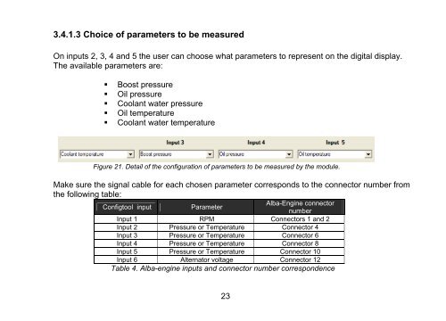
3.4.1.3 Choice of parameters to be measured<br />
On inputs 2, 3, 4 and 5 the user can choose what parameters to represent on the digital display.<br />
The available parameters are:<br />
� Boost pressure<br />
� Oil pressure<br />
� Coolant water pressure<br />
� Oil temperature<br />
� Coolant water temperature<br />
Figure 21. Detail of the configuration of parameters to be measured by the module.<br />
Make sure the signal cable for each chosen parameter corresponds to the connector number from<br />
the following table:<br />
Configtool input Parameter<br />
Alba-Engine connector<br />
number<br />
Input 1 RPM Connectors 1 and 2<br />
Input 2 Pressure or Temperature Connector 4<br />
Input 3 Pressure or Temperature Connector 6<br />
Input 4 Pressure or Temperature Connector 8<br />
Input 5 Pressure or Temperature Connector 10<br />
Input 6 Alternator voltage Connector 12<br />
Table 4. Alba-engine inputs and connector number correspondence<br />
23
![PDF[0.59Mb] - Albatross Control System](https://img.yumpu.com/28676183/1/190x132/pdf059mb-albatross-control-system.jpg?quality=85)