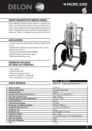
bombas doble membrana manual de instrucciones lista de ... - Sagola
bombas doble membrana manual de instrucciones lista de ... - Sagola
bombas doble membrana manual de instrucciones lista de ... - Sagola
- No tags were found...
You also want an ePaper? Increase the reach of your titles
YUMPU automatically turns print PDFs into web optimized ePapers that Google loves.
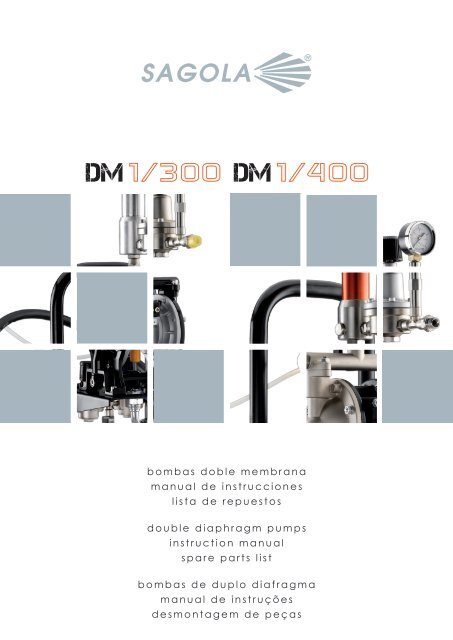
o m b a s d o b l e m e m b r a n am a n u a l d e i n s t r u c c i o n e sl i s t a d e r e p u e s t o sd o u b l e d i a p h r a g m p u m p si n s t r u c t i o n m a n u a ls p a r e p a r t s l i s tb o m b a s d e d u p l o d i a f r a g m am a n u a l d e i n s t r u ç õ e sd e s m o n t a g e m d e p e ç a s
1. ATENCIÓNEste equipo es <strong>de</strong> uso exclusivamente PROFESIONAL.Antes <strong>de</strong> ponerlo en marcha <strong>de</strong>be haber leído y asimiladoen su totalidad todas las indicaciones <strong>de</strong>scritas en esteManual, <strong>de</strong>biendo tenerlas en cuenta y cumplirlas.Deberá conservarlo en un lugar seguro y accesible atodos los usuarios <strong>de</strong>l equipo.El equipo sólo <strong>de</strong>be ser puesto en funcionamiento yutilizado por personas instruidas en su manejo, y exclusivamentepara ser utilizado para los fines previstos.Asimismo, <strong>de</strong>berá tener en cuenta las Normas <strong>de</strong>Prevención <strong>de</strong> acci<strong>de</strong>ntes, los Reglamentos y Directivaspara los Centros <strong>de</strong> trabajo y las Leyes y restriccionesvigentes.SAGOLA S.A., los logotipos <strong>de</strong> SAGOLA y otros productosSAGOLA, mencionados en este <strong>manual</strong>, son marcasregistradas o marcas <strong>de</strong> la empresa SAGOLA S.A.2. INTRODUCCIÓNEl equipo que tiene en su po<strong>de</strong>r pertenece a la familia <strong>de</strong>equipos que trasvasan productos a baja presión, queincluso y a través <strong>de</strong> una pistola, pue<strong>de</strong>n ser directamentepulverizados.Equipo compuesto <strong>de</strong> serie por:- Bomba <strong>de</strong> <strong>doble</strong> <strong>membrana</strong>.- Regulador <strong>de</strong> presión <strong>de</strong> la salida <strong>de</strong>l producto(Versiones DM 01/300 y DM 01/400).- Regulador <strong>de</strong> presión <strong>de</strong> la entrada <strong>de</strong> aire (VersionesDM 01/300 y DM 01/400).- Regulador <strong>de</strong> presión <strong>de</strong> la salida aire (Versiones DM01/300 y DM 01/400).Elementos opcionales y complementarios <strong>de</strong>l equipo:-Mangueras <strong>de</strong> producto-Mangueras <strong>de</strong> aire-Pistolas Aerográficas-Kit Soporte Mural <strong>de</strong>l Equipo-Kits para aplicación <strong>de</strong> productos Abrasivos.3. DATOS TÉCNICOSEl Equipo está compuesto por una bomba neumática <strong>de</strong><strong>doble</strong> <strong>membrana</strong>, a través <strong>de</strong> la que, <strong>de</strong>s<strong>de</strong> un recipienteoriginal se trasvasa producto a presión regulable hastaotro, o hasta un dispositivo pulverizador (Pistola).El equipo pue<strong>de</strong> suministrarse en diferentes versiones:-En su versión básica, compuesto solo por la bomba <strong>de</strong><strong>doble</strong> <strong>membrana</strong> y en versiones standard o especial paraabrasivos, mo<strong>de</strong>los DM Aluminio y DM especial Abrasivos.- Con soporte (móvil o mural) <strong>de</strong> la bomba, reguladores<strong>de</strong> presión <strong>de</strong> aire y producto y <strong>de</strong>pósito <strong>de</strong> gravedad enel que se introduce el producto a trasvasar o aplicar.- Con soporte <strong>de</strong> la bomba (móvil o mural), reguladores<strong>de</strong> presión <strong>de</strong> aire y producto y sonda <strong>de</strong> absorción, quese introduce directamente en el recipiente que contiene elproducto a trasvasar o aplicar.DM Aluminio 300Alimentación <strong>de</strong>l equipo por aire comprimidoRelación <strong>de</strong> presión: 1:1Caudal Máximo: 30 litros/minutoConsumo <strong>de</strong> aire Máximo: 200 Litros/minutoPresión máxima entrada <strong>de</strong> aire: 7 barEntrada <strong>de</strong> aire: 1/4”Entrada <strong>de</strong> Producto: ½”Salida <strong>de</strong> Producto: ½”Peso Neto: 6 kg.Temperatura operativa máxima <strong>de</strong> 50ºCHomologacion CE Ex II 2G XDM Aluminio/AbrasivosAlimentación <strong>de</strong>l equipo por aire comprimidoRelación <strong>de</strong> presión: 1:1Caudal Máximo: 40 litros/minutoConsumo <strong>de</strong> aire Máximo: 580 Litros/minutoPresión máxima entrada <strong>de</strong> aire: 7 barEntrada <strong>de</strong> aire: 1/4”Entrada <strong>de</strong> Producto: ½”Salida <strong>de</strong> Producto: ½”Peso Neto: 6 kg.Temperatura operativa máxima <strong>de</strong> 50ºCHomologacion CE Ex II 2G XEquipo DM 01/300Mismas caracteristicas que DM Aluminio 300Carro soporte o soporte MuralReguladores <strong>de</strong> presión <strong>de</strong> aireRegulador <strong>de</strong> presión <strong>de</strong> producto (Opcional)Deposito <strong>de</strong> producto (Opcional)Sonda <strong>de</strong> absorción (Opcional)Peso: 9.5 Kgs.Equipo DM 01/400Mismas caracteristicas que DM AluminioCarro soporte o soporte MuralReguladores <strong>de</strong> presión <strong>de</strong> aireRegulador <strong>de</strong> presión <strong>de</strong> producto (Opcional)Deposito <strong>de</strong> producto (Opcional)Sonda <strong>de</strong> absorción (Opcional) en versiones standard oabrasivosPeso: 10.5 Kgs.-4-
4. COMPONENTES05140807150913101106041412050316DM 30016DM 4001 Depósito <strong>de</strong> Producto o Sonda <strong>de</strong> Absorción2 Sonda <strong>de</strong> Absorción o Sonda <strong>de</strong> Absorción3 Entrada <strong>de</strong>l producto4 Salida <strong>de</strong>l producto5 Regulador <strong>de</strong> presión <strong>de</strong> aire (Equipo)6 Regulador <strong>de</strong> presión <strong>de</strong> aire ( Pistola)7 Filtro antipulsaciones8 Regulador <strong>de</strong> presión <strong>de</strong> producto9 Tubería <strong>de</strong> retorno <strong>de</strong>l producto (Purga)10 Manómetro (Equipo)11 Manómetro (Pistola)12 Entrada <strong>de</strong> aire al equipo13 Carro <strong>de</strong> Transporte14 Llave <strong>de</strong> paso <strong>de</strong> aire15 Llave <strong>de</strong> purga16 Soporte muralFIG.1-5-
5. ADVERTENCIAS- Antes <strong>de</strong> su puesta en servicio se recomienda limpiar elequipo, ya que es sometido a pruebas <strong>de</strong> funcionamiento,y antes <strong>de</strong> su envasado se le aplica un tratamientointerno <strong>de</strong> protección <strong>de</strong>l que pue<strong>de</strong>n quedar restos.Haga una aplicación <strong>de</strong> diluyente para eliminarlo. Limpielas grasas residuales proce<strong>de</strong>ntes <strong>de</strong>l montaje.- El equipo se suministra <strong>de</strong>spresurizado (sin presión ensu interior).- Antes <strong>de</strong> la puesta en funcionamiento, y especialmente<strong>de</strong>spués <strong>de</strong> cada limpieza y/oreparación, <strong>de</strong>berá comprobar que los componentes <strong>de</strong>lequipo estén perfectamente apretados y que lasmangueras sean técnicamente aptas para las características<strong>de</strong>l equipo y trabajo a realizar, a<strong>de</strong>más <strong>de</strong> flexiblesy estancas (sin fugas). Las piezas <strong>de</strong>fectuosas <strong>de</strong>berácambiarlas o repararlas convenientemente.- Cerciorese <strong>de</strong> que los dispositivos <strong>de</strong> seguridad <strong>de</strong>lequipo funcionen correctamente antes <strong>de</strong> su utilización.- El Equipo es <strong>de</strong> fácil manejo, <strong>de</strong>bido a su diseño y a lasimplicidad <strong>de</strong> sus mecanismos. Utilícelo siguiendo las<strong>instrucciones</strong> <strong>de</strong> uso, mantenimiento y seguridad indicadasen el presente <strong>manual</strong> y realice las prácticas <strong>de</strong>aplicación necesarias para conseguir la calidad <strong>de</strong>acabado <strong>de</strong>seada.- Utilice mangueras antiestáticas SAGOLA a<strong>de</strong>cuadas alproducto a trasvasar.- Deberá conectar siempre el equipo, y todos los elementosque intervienen en el proceso <strong>de</strong> trabajo, a una toma<strong>de</strong> tierra para eliminar la electricidad estática. Verifiqueperiódicamente (una vez a la semana) su continuida<strong>de</strong>léctrica. Si su resistencia supera los limites recomendadoscorrijala. Un equipo sin conexión a tierra, o malrealizada, pue<strong>de</strong> convertir en peligrosa la instalación.- La resistencia <strong>de</strong>rivadora total <strong>de</strong> la línea <strong>de</strong>be ser
8. KITS DE SERVICIOSAGOLA S.A. dispone <strong>de</strong> Kits <strong>de</strong> servicio, indicados enlas láminas <strong>de</strong> <strong>de</strong>spiece, para aten<strong>de</strong>r las reparaciones ysustitución <strong>de</strong> componentes consumibles <strong>de</strong>l equipo.9. PUESTA EN MARCHAAntes <strong>de</strong> cada puesta en marcha y especialmente<strong>de</strong>spués <strong>de</strong> cada limpieza o reparación, <strong>de</strong>berá verificarque todos los elementos estén perfectamente blocados ylos sistemas <strong>de</strong> seguridad <strong>de</strong>l equipo funcionan correctamente.Conecte el equipo a tierra, así como las mangueras, losrecipientes a utilizar y los objetos a pintar.Sitúe siempre el equipo al menos a 6 metros <strong>de</strong> distancia<strong>de</strong> la zona <strong>de</strong> aplicación <strong>de</strong>l producto.La primera vez que utilice su equipo no es necesariorealizar el proceso <strong>de</strong> <strong>de</strong>spresurización, ya que en origense suministra totalmente <strong>de</strong>spresurizado, pero sí lo serácada vez que realice trabajos <strong>de</strong> mantenimiento, limpiezay reparación.Si no se tiene en cuenta esta instrucción <strong>de</strong> seguridad,pue<strong>de</strong>n ocurrir averías, lesiones personales y acci<strong>de</strong>ntes,pudiendo llegar a ser mortales. SAGOLA S.A. no seresponsabiliza <strong>de</strong> eventuales secuelas <strong>de</strong>bidas a incumplimiento<strong>de</strong> estas normas <strong>de</strong> seguridad.10. DESPRESURIZACIÓN1.-Accione el mando <strong>de</strong>l Regulador <strong>de</strong> presión <strong>de</strong> producto(Nº 8 <strong>de</strong> la Figura 1) en sentido <strong>de</strong> las agujas <strong>de</strong>l relojhasta que el manómetro indique una presión <strong>de</strong> 0.5 a 1bar. En el supuesto <strong>de</strong> que la bomba o el equipo no tengaeste regulador <strong>de</strong> presión, cierre el suministro <strong>de</strong> aire almismo.2.-Active el seguro <strong>de</strong> la pistola.3.-Accione el Regulador <strong>de</strong> presión <strong>de</strong> aire <strong>de</strong> entradaaire a la pistola (Nº 5 <strong>de</strong> la Figura 1) girándolo en sentidocontrario a las agujas <strong>de</strong>l reloj.4.-Cierre la llave <strong>de</strong> paso <strong>de</strong> entrada <strong>de</strong> aire a la bomba(Nº 14 <strong>de</strong> la Figura 1) y a continuación accione el Regulador<strong>de</strong> presión <strong>de</strong> entrada <strong>de</strong> aire al equipo (Nº 5 <strong>de</strong> laFigura 1). girándolo en sentido contrario a las agujas <strong>de</strong>lreloj.5.-Desactive el seguro <strong>de</strong> la pistola. Sujetando firmementeuna parte metálica <strong>de</strong> la pistola a la pared <strong>de</strong> un cubometálico puesto a tierra correctamente, accione el gatillopara purgar el producto (dirija el chorro contra la pared<strong>de</strong>l cubo).6.-Active el seguro <strong>de</strong> la pistola.7.-Abra la válvula <strong>de</strong> purga (Nº 15 <strong>de</strong> la Figura 1) habilitandopróximo al equipo un recipiente para verter elproducto. Mantenga abierta la válvula hasta que elequipo esté en condiciones <strong>de</strong> volver a trabajar.Si usted supone que el pico <strong>de</strong> fluido, el filtro o lamanguera están completamente obstruida, o que lapresión no ha sido totalmente eliminada <strong>de</strong>spués <strong>de</strong>haber seguido el procedimiento anteriormente <strong>de</strong>scrito,<strong>de</strong>smonte con cuidado el la manguera reduciendogradualmente la presión hasta que <strong>de</strong>saparezca. Actoseguido limpie la pistola y/o la manguera. En el supuesto<strong>de</strong> que no utilice pistola, complete el ciclo <strong>de</strong> trabajohasta que <strong>de</strong>je <strong>de</strong> salir producto por la bomba o el equipo.11. FUNCIONAMIENTOMUY IMPORTANTESolo si ha realizado correctamente todo el procesoindicado en el apartado <strong>de</strong> DESPRESURIZACIÓN<strong>de</strong>scrito en el Apartado 10, el equipo estará listo parauna nueva puesta en marcha, limpieza, mantenimientoy utilización.La incorrecta realización <strong>de</strong> todo este proceso <strong>de</strong>Despresurización pue<strong>de</strong> generar fallos en el funcionamiento<strong>de</strong>l equipo y <strong>de</strong>terioro <strong>de</strong> sus componentes.Antes <strong>de</strong> proce<strong>de</strong>r a la puesta en marcha <strong>de</strong>l equipo,actúe siguiendo el or<strong>de</strong>n indicado a continuación (si sesiguieron en todos los pasos especificados al efectuar laparada <strong>de</strong>l equipo, este estará en las condiciones acontinuación referidas)1. Abra la válvula <strong>de</strong> purga (Nº 15 <strong>de</strong> la Figura 1) paracolocar el equipo en estado <strong>de</strong> purga2. Accione el Regulador <strong>de</strong> presión <strong>de</strong> entrada <strong>de</strong> aire alequipo (Nº 5 <strong>de</strong> la Figura 1). girándolo en sentido <strong>de</strong> lasagujas <strong>de</strong>l reloj3.- Verifique que la llave <strong>de</strong> entrada <strong>de</strong> aire al equipo (Nº14 <strong>de</strong> la Figura 1) esté abierta.4.- Verifique la estanqueidad <strong>de</strong> todas las conexiones <strong>de</strong>lequipo.11.1. TRASVASE DE PRODUCTO1.- Monte el tubo <strong>de</strong> aspiración en el equipo (blocándolofirmemente) (Nº 3 <strong>de</strong> la Figura 1) e introdúzcalo en elproducto a trasvasar.2.-Verifique que la manguera <strong>de</strong> salida <strong>de</strong> producto seencuentra <strong>de</strong>ntro <strong>de</strong> su recipiente y que está conectadacorrectamente a la bomba.3.- Conecte el equipo (Nº 12 <strong>de</strong> la Figura 1) a la red general<strong>de</strong> aire.4.-Abra la llave <strong>de</strong> paso <strong>de</strong> aire (Nº 14 <strong>de</strong> la Figura 1).5.-Accione el mando <strong>de</strong>l regulador <strong>de</strong> presión (Nº 5 <strong>de</strong> laFigura 1), girándolo en el sentido <strong>de</strong> las agujas <strong>de</strong>l relojhasta que la bomba inicie el movimiento.6.- Aumente progresivamente el giro hasta que observela aspiración <strong>de</strong>l producto. Cuando observe que comienzaa fluir por la salida el producto trasvasado a la velocidad<strong>de</strong>seada cese el giro.11.2. APLICACIÓN CON PISTOLA1.- Monte el tubo <strong>de</strong> aspiración en el equipo (blocándolofirmemente) (Lámina DM01/300 Nº 02 y 06 en LáminaDM01/400) e introdúzcalo en el producto a trasvasar.Verifique que el filtro <strong>de</strong> aspiración (Lámina DM01/300Nº 01 y 07 en Lámina DM01/400) está limpio y correctamenteinstalado.2.- Conecte la manguera y la pistola al equipo (Nº 4 y 6 <strong>de</strong>la Figura 1 y ) blocando fuertemente sus conexiones.-7-
3.- Verifique que la tubería <strong>de</strong> retorno <strong>de</strong>l producto(sonda) (Nº9 figura 1) está fijada e introducida en sucorrespondiente <strong>de</strong>pósito. Abra la llave <strong>de</strong> paso <strong>de</strong> lapurga (Nº15 fig.1).4.- Verifique, girándo los mandos correspondientes ensentido contrario a las agujas <strong>de</strong>l reloj, que los reguladores<strong>de</strong> entrada <strong>de</strong> aire (Nº5 y 6 <strong>de</strong> la Fig.1) están sinpresión.5.- Conecte el equipo (Nº 12 <strong>de</strong> la Fig.1) a la red general<strong>de</strong> aire.6.-Abra la llave <strong>de</strong> paso <strong>de</strong> aire (Nº 14 <strong>de</strong> la Fig.1).7.-Accione el mando <strong>de</strong>l regulador <strong>de</strong> presión (Nº 5 <strong>de</strong> laFig.1), girándolo en el sentido <strong>de</strong> las agujas <strong>de</strong>l relojhasta que la bomba inicie el movimiento. A partir <strong>de</strong> estemomento existirá flujo <strong>de</strong> producto a través <strong>de</strong> la (tubería<strong>de</strong> retorno <strong>de</strong>l producto (sonda) (Nº9 fig.1). Deje quefluya durante 30 segundos para eliminar completamenteel aire existente en el interior <strong>de</strong> la bomba.8.- Cierre la llave <strong>de</strong> paso <strong>de</strong> purga (15 Fig.1).9.-Accione el mando <strong>de</strong>l regulador <strong>de</strong> presión <strong>de</strong> producto(Nº 8 <strong>de</strong> la Fig.1), girándolo en el sentido <strong>de</strong> las agujas<strong>de</strong>l reloj hasta conseguir la presión <strong>de</strong>seada.10.-Dirija la pistola hacia un recipiente y accione el gatillo<strong>de</strong> la misma hasta que empiece a salir producto por elpico <strong>de</strong> fluido sin aire. Una presión <strong>de</strong> producto excesivaocasiona un <strong>de</strong>sgaste prematuro en válvulas y cierres <strong>de</strong>la bomba y pistola, a<strong>de</strong>más <strong>de</strong> un gasto innecesario <strong>de</strong>producto durante la aplicación. En caso <strong>de</strong> tener uncaudal bajo <strong>de</strong> fluido es aconsejable aumentar el paso<strong>de</strong>l pico <strong>de</strong> producto <strong>de</strong> la pistola antes que incrementarla presión <strong>de</strong> trabajo en el regulador <strong>de</strong> presión <strong>de</strong>lequipo.12.-Accione, girándolo en el sentido <strong>de</strong> las agujas <strong>de</strong>lreloj, sobre el mando <strong>de</strong>l regulador <strong>de</strong> aire <strong>de</strong> la pistola(Nº 6 Fig.1) hasta conseguir la presión <strong>de</strong> aire <strong>de</strong>seadapara lograr una óptima aplicación.13.-Ajuste el regulador <strong>de</strong> producto <strong>de</strong> la pistola y elregulador <strong>de</strong> presión <strong>de</strong> producto <strong>de</strong>l equipo (Nº 8 Fig. 1)para controlar el flujo <strong>de</strong> producto proyectado por lapistola.14.-Ajuste el regulador <strong>de</strong> abanico <strong>de</strong> la pistola paraobtener la anchura <strong>de</strong> abanico <strong>de</strong>seada.15.- Realice una prueba <strong>de</strong> aplicación sin compromiso.12. PARADACorta duraciónCuando se produzca una parada <strong>de</strong> corta duración, queno plantee posibles problemas <strong>de</strong> catalizacion o endurecimiento<strong>de</strong>l producto <strong>de</strong>ntro <strong>de</strong>l equipo y accesorios,mantenga la sonda <strong>de</strong> aspiración <strong>de</strong> producto sumergida<strong>de</strong>ntro <strong>de</strong>l producto (si el equipo tiene <strong>de</strong>pósito <strong>de</strong> gravedadno es necesario vaciar el mismo) y aplique el procedimiento<strong>de</strong> Despresurización (Apdo. 10).Finalización <strong>de</strong> trabajo1.- Accione el Regulador <strong>de</strong> presión <strong>de</strong> entrada <strong>de</strong> aire alequipo (Nº 5 <strong>de</strong> la Fig.1) girándolo en sentido contrario alas agujas <strong>de</strong>l reloj hasta conseguir una presión <strong>de</strong> 0 bar.2.- Accione el gatillo <strong>de</strong> la pistola, manteniéndolo accionadohasta que <strong>de</strong>je <strong>de</strong> salir producto,El equipo está ahora listo para proce<strong>de</strong>r a su limpieza.13. LIMPIEZATanto la pistola como las mangueras y el resto <strong>de</strong>l equipo<strong>de</strong>berá limpiarlo con el diluyente a<strong>de</strong>cuado, para eliminartodo resto <strong>de</strong> producto y <strong>de</strong>spués <strong>de</strong> haber concluido eltrabajo. De la efectividad <strong>de</strong> este proceso <strong>de</strong> limpieza<strong>de</strong>pen<strong>de</strong>rá en gran medida la vida útil <strong>de</strong>l equipo.Es necesario limpiar el equipo:- Antes <strong>de</strong> utilizarlo por primera vez, con el fin <strong>de</strong> eliminarlos restos <strong>de</strong> aceite <strong>de</strong> mantenimiento que el equipo trae<strong>de</strong> fábrica.- Después <strong>de</strong> finalizar el trabajo.- Al proce<strong>de</strong>r a aplicar un producto distinto (en color ocaracterísticas) <strong>de</strong>l que estamos pulverizando actualmente.Antes <strong>de</strong> que proceda a la limpieza <strong>de</strong>l equipo <strong>de</strong>beráhaber seguido todos y cada uno <strong>de</strong> los pasos expuestosen el apartado <strong>de</strong> Parada con finalización <strong>de</strong>l trabajo(Apartado 12.2).Esto implica que el equipo y accesorios <strong>de</strong>ben estar<strong>de</strong>spresurizados y sin producto en su interior.Para la limpieza <strong>de</strong>l equipo utilice siempre el diluyentea<strong>de</strong>cuado. Para productos al agua siempre agua, paraotros productos siempre el recomendado por el fabricante<strong>de</strong>l producto a aplicar.Se consi<strong>de</strong>ra que el equipo y sus accesorios estántotalmente limpios, cuando el producto proyectado através <strong>de</strong> la pistola, o que en <strong>de</strong>finitiva fluye por lasalida <strong>de</strong> producto, sea diluyente limpio y exento <strong>de</strong>lproducto aplicado, para lo que habrá <strong>de</strong> renovarse elmismo cuantas veces sea necesario.Una vez limpio el equipo y sus accesorios y comopaso previo a su parada <strong>de</strong>finitiva <strong>de</strong>be aplicarse elProcedimiento <strong>de</strong> <strong>de</strong>spresurización <strong>de</strong>scrito conanterioridad en el Apartado 10 <strong>de</strong>l Manual.- Limpie los filtros <strong>de</strong> la Sonda <strong>de</strong> Absorción, o <strong>de</strong>pósito<strong>de</strong> producto, y <strong>de</strong> la pistola.- Limpie la pistola, mangueras y resto <strong>de</strong>l equipo <strong>de</strong> losrestos <strong>de</strong>l producto aplicado con un trapo impregnado endiluyente.- Mantenga limpias <strong>de</strong> adherencias y elementos extrañoslas zonas <strong>de</strong> cierre <strong>de</strong> paso <strong>de</strong>l producto.- La boquilla <strong>de</strong> producto es un elemento <strong>de</strong> precisión.Cualquier <strong>de</strong>formación, especialmente en los orificios <strong>de</strong>salida <strong>de</strong>l producto pue<strong>de</strong> <strong>de</strong>teriorar su funcionamiento yhacer que la calidad <strong>de</strong> la pulverización sea <strong>de</strong>ficiente eincorrecta.En caso necesario, sumerja la boquilla en diluyente parareblan<strong>de</strong>cer los restos <strong>de</strong> producto o suciedad. Una vezreblan<strong>de</strong>cidos proceda a soplar la boquilla con airecomprimido hasta eliminar los restos <strong>de</strong> producto ydiluyente.- Para realizar las labores <strong>de</strong> limpieza automática <strong>de</strong> lapistola, útiles y accesorios empleados en la mezcla ypreparación para la aplicación <strong>de</strong>l producto, recomendamosel empleo <strong>de</strong> las Lavadoras <strong>de</strong> la gama SAGOLA.13.1 DESPUÉS DE TRASVASE:1.- Accione el mando <strong>de</strong>l regulador <strong>de</strong> entrada <strong>de</strong> aire alequipo (Nº 5 <strong>de</strong> la Figura 1) girándolo en sentido <strong>de</strong> lasagujas <strong>de</strong>l reloj hasta conseguir una presión entre 2-2.5bares.2.- Retire la sonda <strong>de</strong> absorción (Lámina DM 01/300 Nº 02y 06 en Lámina DM 01/400) <strong>de</strong>l recipiente <strong>de</strong> productotrasvasado.3.- Espere hasta que cese la salida <strong>de</strong> producto por lamanguera.4.- Cierre la llave <strong>de</strong> paso <strong>de</strong> aire a la bomba (Nº14Figura 1).-8-
5.-Accione el mando <strong>de</strong>l regulador <strong>de</strong> entrada <strong>de</strong> aire a labomba (Nº 5 <strong>de</strong> la Fig.1) girándolo en sentido contrario alas agujas <strong>de</strong>l reloj.6.- Introduzca la sonda <strong>de</strong> aspiración en un recipientemetálico conectado a tierra y con el diluyente a<strong>de</strong>cuado.7.-introduzca en el diluyente <strong>de</strong>l mismo recipiente metálicola tubería <strong>de</strong> retorno <strong>de</strong>l producto (sonda) (Nº 9 Fig.1).Sujetándola firmemente para evitar salpicaduras.8.- Abra la llave <strong>de</strong> paso <strong>de</strong> aire a la bomba (Nº 14 Fig.1).9.- Acione sobre el mando <strong>de</strong>l regulador <strong>de</strong> entrada <strong>de</strong> aireal equipo (Nª 5 Fig.1) girándolo en el sentido <strong>de</strong> las agujas<strong>de</strong>l reloj, hasta que el equipo se ponga en marcha.10.- Mantenga el equipo en funcionamiento hasta queconsi<strong>de</strong>re que el equipo esté exento <strong>de</strong> producto.13.2 DESPUÉS DE APLICACIÓN CON PISTOLA:1.- Active el seguro <strong>de</strong> la pistola2.- Accione el mando <strong>de</strong>l regulador <strong>de</strong> entrada <strong>de</strong> aire alequipo (Nº 5 <strong>de</strong> la Fig. 1) girándolo en sentido <strong>de</strong> las agujas<strong>de</strong>l reloj hasta conseguir una presión entre 2-2.5 bares.3.- Accione el mando <strong>de</strong>l regulador <strong>de</strong> entrada <strong>de</strong> aire a lapistola (Nº 6 <strong>de</strong> la Fig.1) girándolo en sentido <strong>de</strong> lasagujas <strong>de</strong>l reloj y accione el gatillo <strong>de</strong> la misma paraexpulsar el aire existente en la manguera.4.- Accione el mando <strong>de</strong>l regulador <strong>de</strong> presión <strong>de</strong> producto(Nº 8 <strong>de</strong> la Fig.1) girándolo en sentido <strong>de</strong> las agujas <strong>de</strong>lreloj hasta conseguir una presión <strong>de</strong> 1 bar.5.- Retire la sonda <strong>de</strong> absorción (Lámina DM 01/300 Nº 02y 06 en Lámina DM 01/400) <strong>de</strong>l recipiente <strong>de</strong> productotrasvasado.6.- Desactive el seguro <strong>de</strong> la pistola y coloquela en unrecipiente metálico, conectado a tierra y con el diluyentea<strong>de</strong>cuado. Tenga la precaución <strong>de</strong> apoyar la propia pistolaa este mismo recipiente, conectándola también a tierra.7.- Accione y mantenga pulsado el gatillo <strong>de</strong> la pistolahasta que cese la salida <strong>de</strong> producto por la misma.8.- Sin <strong>de</strong>jar <strong>de</strong> mantener pulsado el gatillo <strong>de</strong> la pistola,cierre la llave <strong>de</strong> paso <strong>de</strong> aire a la bomba (Nº 14 Fig.1).9.- Active <strong>de</strong> nuevo el seguro <strong>de</strong> la pistola.10.- Accione el mando <strong>de</strong>l regulador <strong>de</strong> entrada <strong>de</strong> aire alequipo (Nº 5 <strong>de</strong> la Fig.1) girándolo en sentido contrario alas agujas <strong>de</strong>l reloj.11.- Accione el mando <strong>de</strong>l regulador <strong>de</strong> salida <strong>de</strong> presión<strong>de</strong> producto (Nº 8 <strong>de</strong> la Fig.1) girándolo en sentidocontrario a las agujas <strong>de</strong>l reloj.12.- Abra y mantenga abierta la llave <strong>de</strong> purga (Nº 15Fig.1), situando la tubería <strong>de</strong> retorno <strong>de</strong>l producto (sonda)(Nº 9 Fig.1) en el recipiente <strong>de</strong>l producto a aplicar.13.- Coloque la sonda <strong>de</strong> absorción (Lámina DM 01/300Nº 02 y 06 en Lámina DM 01/400) en un recipiente metálico,conectado a tierra y con el diluyente a<strong>de</strong>cuado.Tenga la precaución <strong>de</strong> apoyar la sonda a este mismorecipiente, conectándola también a tierra.14.- Coloque la tubería <strong>de</strong> retorno <strong>de</strong> producto <strong>de</strong> lapurga (sonda) (Nº 9 Fig. 1) en el mismo recipiente metálicoque contiene el diluyente y fijela a<strong>de</strong>cuadamente paraevitar salpicaduras.15.- Abra la llave <strong>de</strong> paso <strong>de</strong> aire a la bomba (Nº 14 Fig.1).16.- Accione el mando <strong>de</strong>l regulador <strong>de</strong> entrada <strong>de</strong> aire alequipo (Nº 5 <strong>de</strong> la Fig. 1) girándolo en sentido <strong>de</strong> lasagujas <strong>de</strong>l reloj hasta que el equipo se ponga en marcha.17.- Mantenga el equipo en funcionamiento hasta queconsi<strong>de</strong>re que el equipo está exento <strong>de</strong> producto.18.- Cierre la llave <strong>de</strong> paso <strong>de</strong> salida <strong>de</strong> producto (Nº 15 Fig.1).19.- Coloque la pistola en un recipiente metálico, conectadoa tierra y con el diluyente a<strong>de</strong>cuado. Tenga laprecaución <strong>de</strong> apoyar la propia pistola a este mismorecipiente, conectándola también a tierra.20.- Desactive el seguro <strong>de</strong> la pistola.21.- Accione y mantenga pulsado el gatillo <strong>de</strong> la pistolahasta que cese la salida <strong>de</strong> producto por la misma.22.- Accione el mando <strong>de</strong>l regulador <strong>de</strong> presión <strong>de</strong>producto (Nº 8 <strong>de</strong> la Fig.1) girándolo en sentido <strong>de</strong> lasagujas <strong>de</strong>l reloj hasta conseguir una presión <strong>de</strong> 1 bar.23.- Comenzará a salir diluyente a través <strong>de</strong> la pistola.Mantenga en marcha el equipo hasta que observe queéste ya está exento <strong>de</strong> producto.24.- Cierre la llave <strong>de</strong> paso <strong>de</strong> aire al equipo (Nº 14 <strong>de</strong> laFig.1), manteniendo el gatillo <strong>de</strong> la pistola accionadohasta que <strong>de</strong>je <strong>de</strong> salir diluyente por la pistola.25.- Accione el mando <strong>de</strong>l regulador <strong>de</strong> presión <strong>de</strong> producto(Nº 8 <strong>de</strong> la Fig.1) girándolo en sentido contrario a lasagujas <strong>de</strong>l reloj hasta conseguir una presión <strong>de</strong> 0 bar.26.- Accione el mando <strong>de</strong>l regulador <strong>de</strong> entrada <strong>de</strong> aire alequipo (Nº 5 <strong>de</strong> la Fig.1) girándolo en sentido contrario a lasagujas <strong>de</strong>l reloj.27.- Abra la llave <strong>de</strong> paso <strong>de</strong> purga (Nº 15 Fig.1).13.3. FILTRO ANTIPULSACIONES (Lámina DM 01/300Nº 14 y 04 en Lámina DM 01/400):1.- Vacíe <strong>de</strong> producto el equipo y realice el procedimiento<strong>de</strong> <strong>de</strong>scompresión.2.- Desenrosque la tapa <strong>de</strong>l filtro antipulsaciones.3.- Extraiga el filtro <strong>de</strong> producto (Lámina DM 01/300 Nº 16y Nº 27 en Lámina DM 01/400) y limpielo con el diluyentea<strong>de</strong>cuado, o sustitúyalo si proce<strong>de</strong>.4.- Monte a<strong>de</strong>cuadamente el filtro <strong>de</strong> producto.5.- Monte, roscando a tope, la tapa <strong>de</strong>l filtro antipulsaciones.IMPORTANTELa pistola pue<strong>de</strong> limpiarla con diluyentes o <strong>de</strong>tergentesen una lavadora <strong>de</strong> pistolas.Si opta por este sistema <strong>de</strong> lavado, aconsejamos tengapresente las siguientes consi<strong>de</strong>raciones que, <strong>de</strong> noseguirlas, pue<strong>de</strong>n <strong>de</strong>teriorar la pistola, y en todo casohacen per<strong>de</strong>r la garantía:- No sumerja la pistola en disolvente o <strong>de</strong>tergente más <strong>de</strong>lo necesario para la limpieza.- No utilice la pistola inmediatamente <strong>de</strong>spués <strong>de</strong> finalizarla limpieza.- Asegúrese <strong>de</strong> que no existe diluyente o <strong>de</strong>tergente ensu interior y está totalmente exenta <strong>de</strong>l mismo.14. MANTENIMIENTOAntes <strong>de</strong> iniciar el trabajo, verifique el estado <strong>de</strong> lasmangueras <strong>de</strong> producto, así como las conexiones <strong>de</strong> loselementos por los que fluye el producto.Para efectuar el mantenimiento o una reparación, <strong>de</strong>sconectepreviamente el equipo <strong>de</strong> la red <strong>de</strong> aire comprimido.Nunca mueva el equipo arrastrándolo por las mangueras.No se <strong>de</strong>ben utilizar gran<strong>de</strong>s esfuerzos ni herramientasina<strong>de</strong>cuadas para el mantenimiento y limpieza <strong>de</strong>lequipo. Algunas reparaciones <strong>de</strong>ben realizarse a vecescon herramientas especiales. En este supuesto <strong>de</strong>beráponerse en contacto con el Servicio <strong>de</strong> atención al cliente<strong>de</strong> SAGOLA. La manipulación <strong>de</strong>l producto por personalno autorizado extingue la garantía <strong>de</strong>l mismo.Es imprescindible hacer una revisión periódica <strong>de</strong>l equipopara verificar el estado <strong>de</strong> sus componentes y sustituirloscuando no estén en perfectas condiciones.En la mayoría <strong>de</strong> usos no es preciso realizar engrases enla bomba, excepto en las juntas tóricas que <strong>de</strong>bieranengrasarse durante alguna reparación.Cuando sea precisa la lubricación <strong>de</strong>l aire, hágalo conSAE 10 sin <strong>de</strong>tergente, y regule el lubricador <strong>de</strong> aire a nomás <strong>de</strong> una gota por minutoPARA OBTENER EL MEJORRESULTADO POSIBLE UTILICESIEMPRE REPUESTOS ORIGINALES SAGOLAASEGURAN UNA TOTAL INTERCAMBIABILIDAD,SEGURIDAD Y FUNCIONAMIENTO PERFECTOS.-9-
DM1/3(*) Min. 5 u.1614ed. 10510802150320111206040907180619130523242221101701Nº Cod. U.01 83660047 102 86465206 103 86410082 104 86410122 105 11020420 106 55751802 207 49000081 208 86464715 109 30090091 110 85760079 1Nº Cod. U.11 85770030 112 85760024 213 30910105 114 56413507 115 54250802 116 83660009 117 56411806 118 87260816 419 80860504 420 57550106 1Nº Cod. U.21 85760012 122 57450909 123 84760004 124 83660001 125 84760029 126 85770033 127 86463904 128 87560037 131 57110202 132 51911518 1Nº Cod. U.33 57810341 134 84560002 135 85760302 136 85770043 137 87260826 638 55752004 139 49000474 140 49000475 141 49000476 142 49000477 1Nº Cod. U.43 49000478 144 49000479 145 49000480 146 49000481 147 49000482 148 49000483 149 49000484 150 49000485 151 56418583 1-10-
DM2/3(*) Min. 5 u.ed. 1033323425372731263612283835Nº Cod. U.01 83660047 102 86465206 103 86410082 104 86410122 105 11020420 106 55751802 207 49000081 208 86464715 109 30090091 110 85760079 1Nº Cod. U.11 85770030 112 85760024 213 30910105 114 56413507 115 54250802 116 83660009 117 56411806 118 87260816 419 80860504 420 57550106 1Nº Cod. U.21 85760012 122 57450909 123 84760004 124 83660001 125 84760029 126 85770033 127 86463904 128 87560037 131 57110202 132 51911518 1Nº Cod. U.33 57810341 134 84560002 135 85760302 136 85770043 137 87260826 638 55752004 139 49000474 140 49000475 141 49000476 142 49000477 1Nº Cod. U.43 49000478 144 49000479 145 49000480 146 49000481 147 49000482 148 49000483 149 49000484 150 49000485 151 56418583 1-11-
DM3/3(*) Min. 5 u.ed. 1048424643391314474541444442 40435045394941Nº Cod. U.01 83660047 102 86465206 103 86410082 104 86410122 105 11020420 106 55751802 207 49000081 208 86464715 109 30090091 110 85760079 1Nº Cod. U.11 85770030 112 85760024 213 30910105 114 56413507 115 54250802 116 83660009 117 56411806 118 87260816 419 80860504 420 57550106 1Nº Cod. U.21 85760012 122 57450909 123 84760004 124 83660001 125 84760029 126 85770033 127 86463904 128 87560037 131 57110202 132 51911518 1Nº Cod. U.33 57810341 134 84560002 135 85760302 136 85770043 137 87260826 638 55752004 139 49000474 140 49000475 141 49000476 142 49000477 1Nº Cod. U.43 49000478 144 49000479 145 49000480 146 49000481 147 49000482 148 49000483 149 49000484 150 49000485 151 56418583 1-12-
DM1/3(*) Min. 5 u.22141 Standard2 Special0414271 - 602 - 100ed. 10232024110810 091013191 Standard2 Special0501 22180673150224 251221162617033031 290728Nº Cod. U.01 85760201 102 56410058 103 84663812 104 83660053 105 54250802 106 86465206 107 83660047 108 85762125 109 80860036 110 80860052 211 85760059 112 50850004 413 54550016 214 11020420 115 55752117 216 56411807 1Nº Cod. U.17 85760009 118 86410082 119/1 30910101 119/2 30910102 120/1 52410019 120/2 86464717 121 80860504 2422 57550106 223 55750802 124 55750803 225 57251011 426 57450909 427/1 83660030 127/2 83660029 128 85760079 129 30090091 1Nº Cod. U.30 84760004 131 83660001 132 85770033 133 86463904 134/1 87560037 134/2 87560039 137 57110202 138 51911518 139 57810341 140 84560002 141 85760302 142 85770043 143 87260826 644 55752004 145 85760024 146 85762117 5Nº Cod. U.47 85761101 248/1 30090020 148/2 30090092 149 81560009 250 56418581 151 87160024 152 87260027 453/1 30090017 153/2 30090096 154 82960101 255 82960102 256 30090018 157 81960601 158 81560010 259 83160717 160 80860069 2Nº Cod. U.61 80660011 362 86462106 263 80660303 264 50650304 265 50850402 466 85770081 167 87261031 268 57450904 469 85761902 170 54250946 571 30090019 172 84760029 173 56418582 1-13-
DM2/3(*) Min. 5 u.ed. 10393840 7243333732424544341 Standard2 Special41Nº Cod. U.01 85760201 102 56410058 103 84663812 104 83660053 105 54250802 106 86465206 107 83660047 108 85762125 109 80860036 110 80860052 211 85760059 112 50850004 413 54550016 214 11020420 115 55752117 216 56411807 1Nº Cod. U.17 85760009 118 86410082 119/1 30910101 119/2 30910102 120/1 52410019 120/2 86464717 121 80860504 2422 57550106 223 55750802 124 55750803 225 57251011 426 57450909 427/1 83660030 127/2 83660029 128 85760079 129 30090091 1Nº Cod. U.30 84760004 131 83660001 132 85770033 133 86463904 134/1 87560037 134/2 87560039 137 57110202 138 51911518 139 57810341 140 84560002 141 85760302 142 85770043 143 87260826 644 55752004 145 85760024 146 85762117 5Nº Cod. U.47 85761101 248/1 30090020 148/2 30090092 149 81560009 250 56418581 151 87160024 152 87260027 453/1 30090017 153/2 30090096 154 82960101 255 82960102 256 30090018 157 81960601 158 81560010 259 83160717 160 80860069 2Nº Cod. U.61 80660011 362 86462106 263 80660303 264 50650304 265 50850402 466 85770081 167 87261031 268 57450904 469 85761902 170 54250946 571 30090019 172 84760029 173 56418582 1-14-
DM3/3(*) Min. 5 u.ed. 1052462621517021 26476966481 Standard2 Special56575065 68586456605563596070617126 21 6267 54531 Standard2 Special46212649481 Standard2 SpecialNº Cod. U.01 85760201 102 56410058 103 84663812 104 83660053 105 54250802 106 86465206 107 83660047 108 85762125 109 80860036 110 80860052 211 85760059 112 50850004 413 54550016 214 11020420 115 55752117 216 56411807 1Nº Cod. U.17 85760009 118 86410082 119/1 30910101 119/2 30910102 120/1 52410019 120/2 86464717 121 80860504 2422 57550106 223 55750802 124 55750803 225 57251011 426 57450909 427/1 83660030 127/2 83660029 128 85760079 129 30090091 1Nº Cod. U.30 84760004 131 83660001 132 85770033 133 86463904 134/1 87560037 134/2 87560039 137 57110202 138 51911518 139 57810341 140 84560002 141 85760302 142 85770043 143 87260826 644 55752004 145 85760024 146 85762117 5Nº Cod. U.47 85761101 248/1 30090020 148/2 30090092 149 81560009 250 56418581 151 87160024 152 87260027 453/1 30090017 153/2 30090096 154 82960101 255 82960102 256 30090018 157 81960601 158 81560010 259 83160717 160 80860069 2Nº Cod. U.61 80660011 362 86462106 263 80660303 264 50650304 265 50850402 466 85770081 167 87261031 268 57450904 469 85761902 170 54250946 571 30090019 172 84760029 173 56418582 1-15-
16. SEGURIDAD Y SALUDPara efectuar el mantenimiento, una reparación o limpieza,<strong>de</strong>sconecte previamente el equipo <strong>de</strong> la red <strong>de</strong> airecomprimido, <strong>de</strong>spués <strong>de</strong> haber realizado correctamenteel proceso <strong>de</strong> DESPRESURIZACIÓN <strong>de</strong>scrito en elApartado 10 <strong>de</strong>l Manual.No dirija nunca la proyección <strong>de</strong>l equipo sobre sí mismo,personas ajenas o animales. Los diluyentes y medios <strong>de</strong>proyección empleados pue<strong>de</strong>n producir lesiones graves.En este equipo, el producto se proyecta a baja presión.Una proyección o salpicadura <strong>de</strong>l producto a los ojospue<strong>de</strong> ser causa <strong>de</strong> graves daños.Nunca trate <strong>de</strong> <strong>de</strong>tener el chorro <strong>de</strong> la aplicación, o unafuga con la mano o cualquier parte <strong>de</strong> su cuerpo. Si tienela sensación <strong>de</strong> haber recibido la proyección <strong>de</strong>l productoen su piel, SOLICITE INMEDIATAMENTE ATENCIÓNMEDICA. Esta inci<strong>de</strong>ncia no <strong>de</strong>be ser tratada como unsimple corte. Indique al Médico con la mayor precisiónposible el producto con el que se ha producido la misma.Los locales <strong>de</strong>ben estar dotados <strong>de</strong> ventilación suficientey acor<strong>de</strong> con las normativas y disposiciones vigentes alrespecto. En el entorno <strong>de</strong>l equipo sólo <strong>de</strong>be existir lacantidad <strong>de</strong> producto y diluyente necesarios para eltrabajo que se está realizando. Después <strong>de</strong> finalizar elmismo <strong>de</strong>berá retornar los diluyentes y productos aaplicar, a su lugar específico <strong>de</strong> almacenamiento. Mantenerla zona <strong>de</strong> trabajo limpia y exenta <strong>de</strong> <strong>de</strong>sechos potencialmentepeligrosos (Diluyentes, trapos, etc... ).Durante el trabajo y en la zona <strong>de</strong> trabajo, no <strong>de</strong>be existirninguna fuente <strong>de</strong> ignición (fuego abierto, cigarrillosencendidos, etc.), ya que durante el mismo se pue<strong>de</strong>ngenerar gases fácilmente inflamables. Asimismo <strong>de</strong>beráutilizar la protección laboral homologada (respiratoria,auditiva, etc.) <strong>de</strong> acuerdo con las Normativas establecidasal respecto.Si el equipo se utiliza <strong>de</strong> forma ina<strong>de</strong>cuada o se alteransus componentes, pue<strong>de</strong>n aparecer daños materiales yprovocar graves secuelas sanitarias en el propio cuerpo,en personas ajenas y/o animales, pudiendo llegar inclusola muerte.SAGOLA, S.A. no se responsabiliza <strong>de</strong> estos dañosproducidos por el mal uso <strong>de</strong>l equipo.Las piezas en movimiento son susceptibles <strong>de</strong> causarlesiones. Manténgase a distancia <strong>de</strong> las mismas cuandoponga en marcha el equipo o lo esté utilizando.Utilice siempre equipos respiratorios homologados conformea las Normativas y Reglamentos vigentes para protegerse<strong>de</strong> las emanaciones producidas en la aplicación.No supere nunca la presión máxima <strong>de</strong> trabajo. Losequipos están tarados por el fabricante <strong>de</strong> acuerdo con lasprestaciones <strong>de</strong> diseño <strong>de</strong>scritas en sus características.Como medida preventiva general se aconseja que utilicegafas protectoras, <strong>de</strong> acuerdo con las normativas ycaracterísticas ambientales específicas <strong>de</strong>l Centro <strong>de</strong>trabajo y las Normativas vigentes.Utilice guantes al manipular el producto (ver recomendaciones<strong>de</strong>l fabricante) y al limpiar la pistola Si durante lautilización <strong>de</strong> la pistola el nivel sonoro ambiental sobrepasa90 dB. Es recomendable el uso <strong>de</strong> protectores acústicoshomologados. El equipo en sí mismo no propicianingún riesgo mecánico <strong>de</strong> perforaciones, impactos opinzamientos, salvo los <strong>de</strong>rivables <strong>de</strong> instalacionesin<strong>de</strong>bidas o manipulaciones incorrectas.UTILICE MANGUERAS ANTIESTÁTICAS SAGOLAPARA ELIMINAR LAS POSIBLES DESCARGASELÉCTRICAS QUE PUDIERAN GENERAR RIESGOSDE INCENDIO O EXPLOSIÓN.La manipulación <strong>de</strong>l equipo, requiere una atencióna<strong>de</strong>cuada, para evitar que se produzcan en el mismo<strong>de</strong>terioros generadores <strong>de</strong> situaciones <strong>de</strong> peligro para elusuario o las personas que se hallen próximas, comoconsecuencia <strong>de</strong> escapes, roturas, etc.El equipo está preparado para su uso a temperaturaambiente. La temperatura máxima <strong>de</strong> servicio es <strong>de</strong>50ºC.La utilización <strong>de</strong> disolventes y/o <strong>de</strong>tergentes que contenganhidrocarburos halogenados (Tricloretano, Cloruro <strong>de</strong>metilo, etc.), pue<strong>de</strong> originar reacciones químicas en elequipo, así como en sus componentes cincados (eltricloroetano mezclado con pequeñas cantida<strong>de</strong>s <strong>de</strong>agua produce ácido clorhídrico). Debido a ello, talescomponentes pue<strong>de</strong>n oxidarse y en caso extremos, lareacción química originada pue<strong>de</strong> efectuarse <strong>de</strong> formaexplosiva.Recomendamos que utilicen productos que no contenganlos componentes mencionados. En ningún caso se<strong>de</strong>ben utilizar ácidos, sosa ( álcalis, o <strong>de</strong>capantes, etc.)para su limpieza.En general, toda manipulación <strong>de</strong>l equipo <strong>de</strong>be realizarseteniendo la precaución <strong>de</strong> no <strong>de</strong>teriorarlo. Los racores <strong>de</strong>unión y las conexiones en general <strong>de</strong>ben estar bienapretados y en buen estado <strong>de</strong> uso.Las normas <strong>de</strong> seguridad <strong>de</strong>ben estar comprendidas yaplicadas El incumplimiento <strong>de</strong> las indicaciones <strong>de</strong>lpresente <strong>manual</strong> pue<strong>de</strong> ocasionar inci<strong>de</strong>ntes que pue<strong>de</strong>nrepercutir en la integridad física <strong>de</strong>l usuario u otras personaso animales.Respete y cumpla las indicaciones relativas a la preservación<strong>de</strong>l medio ambiente.17. OBSERVACIONESObtendrá una buena pulverización y consecuentementeuna buena calidad <strong>de</strong> acabado, siguiendo las <strong>instrucciones</strong><strong>de</strong>l presente <strong>manual</strong>.Si tiene alguna duda al respecto, contacte con el Servicio<strong>de</strong> Atención al Cliente <strong>de</strong> SAGOLA S.A.-16-
18. CONDICIONES DE GARANTÍAEste aparato ha sido fabricado con rigurosa precisión,habiendo sido sometido a numerosos controles antes <strong>de</strong>su salida <strong>de</strong> fábrica.La GARANTÍA concedida es <strong>de</strong> 3 años, a partir <strong>de</strong> lafecha <strong>de</strong> compra, que será indicada por el establecimientoven<strong>de</strong>dor en el lugar habilitado al respecto, junto consu sello.Una vez recepcionado el equipo, cumplimente la garantíay remítala al fabricante para su validación.Esta GARANTÍA cubre cualquier <strong>de</strong>fecto <strong>de</strong> fabricación,que será subsanado sin cargo para el comprador. Sinembargo quedan expresamente excluidas todas aquellasaverías resultantes <strong>de</strong> un mal uso <strong>de</strong>l equipo, tales comoconexiones incorrectas, rotura por caídas ó similares,<strong>de</strong>sgaste normal <strong>de</strong> componentes y en general cualquier<strong>de</strong>ficiencia no imputable a la fabricación <strong>de</strong>l aparato.Asimismo se per<strong>de</strong>rá la GARANTÍA cuando se constateque el aparato ha sido manipulado por personas ajenas anuestro Servicio <strong>de</strong> Asistencia Técnica.Esta GARANTÍA no respalda los compromisos adquiridoscon cualquier persona ajena a nuestro ServicioTécnico.En caso <strong>de</strong> avería durante el periodo <strong>de</strong> garantía, adjunteal aparato el certificado <strong>de</strong> garantía <strong>de</strong>bidamente cumplimentado,y entréguelo en el Servicio <strong>de</strong> Asistencia quemás le interese, o bien poniéndose en contacto confábricaQueda excluida cualquier exigencia <strong>de</strong> más trascen<strong>de</strong>nciacontra el proveedor, en particular la in<strong>de</strong>mnizaciónpor daños y perjuicios. Esto se aplica igualmente a losdaños que se originasen durante el asesoramiento, laadquisición <strong>de</strong> practica y la <strong>de</strong>mostración.Las prestaciones por garantía no tienen por consecuenciauna prolongación <strong>de</strong>l periodo <strong>de</strong> la misma.Reservadas las modificaciones Técnicas19. TABLA DE AVERÍASAvería Causa <strong>de</strong> la avería ReparaciónSale producto porel escape <strong>de</strong> aire.Burbujas <strong>de</strong> aireen la salida <strong>de</strong>producto.La bomba se paraexpulsando el airepor el escape.Membrana rota.Tornillo <strong>de</strong> <strong>membrana</strong> insuficientementeapretado o junta <strong>de</strong>teriorada.Tubería <strong>de</strong> succióninsuficientemente apretada.Junta plana tornillo<strong>membrana</strong> <strong>de</strong>teriorada.Tornillo <strong>de</strong> la <strong>membrana</strong>insuficientemente apretado.Juntas <strong>de</strong> vaso en eldistribuidor <strong>de</strong>terioradas.Placa distribuidor y/oinserto <strong>de</strong>teriorados.Camisa y/o bulón <strong>de</strong>teriorados.Juntas tóricas <strong>de</strong>terioradas.Juntas tóricas <strong>de</strong>l bulón(nº 9 figura-1) <strong>de</strong>fectuosas.Sustituir <strong>membrana</strong>.Desmontar y apretar o sustituir.Apretar.Apretar o sustituir.Apretar.Sustituir.Sustituir.Sustituir.Sustituir.Sustituir por juntas nuevas.No se aten<strong>de</strong>rá en garantía ningún aparato <strong>de</strong>l cual noconste en los archivos <strong>de</strong> SAGOLA S.A. el resguardoadjunto, <strong>de</strong>l certificado <strong>de</strong> garantía <strong>de</strong>bidamente cumplimentado.-17-
Avería Causa <strong>de</strong> la avería ReparaciónPoco aporte <strong>de</strong>material.Entrada o presión <strong>de</strong> aire insuficiente.Manguera <strong>de</strong> salida <strong>de</strong> productoAbrir regulador <strong>de</strong> entrada <strong>de</strong> aire.Limpiar manguera <strong>de</strong> salida oatascada.sustituir.Manguera <strong>de</strong> aspiración suelta o Apretar manguera <strong>de</strong> aspiración<strong>de</strong> diámetro pequeño.o colocar manguera <strong>de</strong> diámetroa<strong>de</strong>cuado para el producto autilizar (en función <strong>de</strong> laviscosidad <strong>de</strong>l mismo).Filtro antipulsaciones, absorcióno pistola sucios.Limpiar o sustituir.Válvulas <strong>de</strong> producto sucias,Limpiar válvulas o sustituir.pegadas o <strong>de</strong>terioradas..Racores o conexiones <strong>de</strong> entrada Apretar conexiones firmemente.<strong>de</strong> producto flojos.La bomba cambia<strong>de</strong> ciclos estandola salida <strong>de</strong>producto cerrada.Asiento <strong>de</strong> válvula o bola cerradoo <strong>de</strong>fectuoso.Junta tórica <strong>de</strong> válvula <strong>de</strong>teriorada.Limpiar o sustituir.Sustituir.La bomba cambia<strong>de</strong> ciclos estandola salida <strong>de</strong>producto cerrada.Tubería <strong>de</strong> succióninsuficientemente apretada.Junta plana tornillo<strong>membrana</strong> <strong>de</strong>teriorada.Tornillo <strong>de</strong> la <strong>membrana</strong>insuficientemente apretado.Tornillo <strong>de</strong> la <strong>membrana</strong>insuficientemente apretado.Sustituir.Sustituir.Sustituir.Sustituir.20. DECLARACIÓN DE CONFORMIDAD CE PARA MÁQUINASSegún la directiva 2006/42/CEFabricante:SAGOLA S.A.Dirección:Calle Urartea, 6 · 01010 VITORIA-GASTEIZ (Álava) · ESPAÑADeclaramos que el producto:Marca:SAGOLAMo<strong>de</strong>lo: DM 1/300 - DM 1/400Se han aplicado las siguientes normas armonizadas (o parte <strong>de</strong> ellas en):Normas <strong>de</strong> diseño y construcción UNE EN 12100, EN 809, EN 12621, EN 12162, EN 1127-1 Y EN 13463-1Se encuentran disponibles, la documentación técnica completa y las <strong>instrucciones</strong> <strong>de</strong> servicio <strong>de</strong>l producto en la versiónoriginal, así como en los idiomas comunitarios <strong>de</strong> los usuarios.En Vitoria-Gasteiz, a 01/07/2014-18-
In<strong>de</strong>x1. Warning page 202. Introduction page 203. Technical data page 204. Components page 215. Warnings page 226. Useful advice page 227. Functional <strong>de</strong>scription of the equipment page 228. Service kits page 239. Start up page 2310. Depressurisation page 2311. Operation page 2311.1. Product transfer page 2311.2. Application with spray gun page 2312. Shut down page 2412.1. Short duration page 2412.2. Ending the job page 2413. Cleaning page 2413.1. After transfer page 2413.2. After spray gun application page 2513.3. Antipulsations filter page 2514. Maintenance page 2515. Product breakdown page 2616. Health and safety page 2717. Remarks page 2718. Guarantee terms page 2819. Malfunctions table page 2820. Conformity <strong>de</strong>claration page 29-19-
1. WARNINGThis equipment is for PROFESSIONAL use only. Beforestarting it up you must have read and un<strong>de</strong>rstood all thegui<strong>de</strong>lines <strong>de</strong>scribed in this <strong>manual</strong>, taking them intoaccount and fulfilling them.This <strong>manual</strong> must be kept in a safe place, accessible to allthe users of the equipment.The unit must be started and used exclusively by personnelinstructed in its use and must be employed only for thepurpose for which it was <strong>de</strong>signed.Likewise, the acci<strong>de</strong>nt prevention standards, regulations,work centre directives and current legislation and restrictionsmust be taken into consi<strong>de</strong>ration at all times.SAGOLA S.A., the SAGOLA logos and other SAGOLAproducts mentioned in this <strong>manual</strong> are registered tra<strong>de</strong>marksor brand names of the company SAGOLA S.A.2. INTRODUCTIONThe equipment you now have belongs to a family ofproducts that transfer products at low pressure, which bymeans of a spray gun, may be sprayed on directly.The standard equipment is comprised of:- Double membrane pump- Pressure regulator for the outlet of the product (VersionsDM01/300 and DM01/400)- Pressure regulator for the air inlet (Versions DM01/300and DM01/400)- Pressure regulator for the air outlet (Versions DM01/300and DM01/400)Optional and complementary elements for the unit:-Product hoses-Air hoses.-Spray guns-Wall bracket kit for the equipment-Kits for applying abrasive products3. TECHNICAL DATAThe equipment unit is comprised of a dual membranepneumatic pump, by means of which from an originalcontainer product is transferred to another at adjustablepressure or to a spraying <strong>de</strong>vice (spray gun).The unit can be supplied in different versions:-In its basic version it is solely comprised of a dual membranepump and in the standard versions or special onesfor abrasives, of the DM aluminium and the DM specialabrasives mo<strong>de</strong>ls.- With pump bracket (mobile or wall-mounted), air andproduct pressure regulators and a gravity tank into whichthe product to be transferred or applied is dumped.- With pump bracket (mobile or wall-mounted), air andproduct pressure regulators and an absorption probe,which is directly inserted into the tank that contains theproduct to be transferred or applied.DM Aluminium 300Equipment unit fed by compressed airPressure ratio: 1:1Maximum flow rate: 30 litres/minuteMaximum air consumption: 200 Litres/minuteMaximum air inlet pressure: 7 barAir inlet: 1/4”Product inlet: ½”Product outlet: ½”Net weight: 6 kg.Maximum operating temperature 50ºCCE Ex II 2G X type approvedDM Aluminium/AbrasivesEquipment unit fed by compressed airPressure ratio: 1:1Maximum flow rate: 40 litres/minuteMaximum air consumption: 580 Litres/minuteMaximum air inlet pressure: 7 barAir inlet: 1/4”Product inlet: ½”Product outlet: ½”Net weight: 6 kg.Maximum operating temperature 50ºCCE Ex II 2G X type approvedDM 01/300 equipment unitThe same features as for DM Aluminium 300Carriage bracket or wall bracketAir flow regulatorsProduct pressure regulator (Optional)Product tank (Optional)Absorption probe (Optional)Weight: 9,5 Kg.DM 01/400 equipment unitThe same features as for DM AluminiumCarriage bracket or wall bracketAir flow regulatorsProduct pressure regulator (Optional)Product tank (Optional)Absorption probe (Optional) in standard or abrasiveversionsWeight: 10.5 Kgs.-20-
4. COMPONENTS05140807150913101106041412050316DM 30016DM 4001 Product tank or absorption probe2 Absorption probe or absorption probe3 Product inlet4 Product outlet5 Air pressure regulator (equipment)6 Air pressure regulator (spray gun)7 Antipulsations filter8 Product pressure regulator9 Product return pipe (purge)10 Pressure gauge (equipment)11 Pressure gauge (spray gun)12 Air inlet to the equipment13 Transport carriage14 Air passage tap15 Bleeding tap16 Wall supportFIG.1-21-
5. WARNINGS- Before putting the unit into operation, we recommendthat you clean the equipment as this has been subjectedto functional tests and before packaging it is treatedinternally with a protective coating, some of which maystill remain.Apply solvent to eliminate this. Remove any residualgrease applied during assembly.- The unit is supplied <strong>de</strong>pressurised (without pressureinsi<strong>de</strong>).- Before starting up and especially after each cleaningand/orrepair procedure, you must check that the components ofthe unit are perfectly tightened and that the hoses aretechnically suited to the features of the equipment and thework to be carried out, in addition to being flexible andsealed (without leaks). Faulty parts must be replaced orrepaired as appropriate.- Check that the unit’s safety <strong>de</strong>vices work properly beforeusing it.- The unit is easy to handle thanks to its <strong>de</strong>sign and thesimplicity of its mechanisms. Use it according to theoperating, maintenance and safety instructions indicatedin this <strong>manual</strong> and follow the application methods indicatedto obtain the required finish quality.- Use SAGOLA anti-static hoses suited to the product tobe transferred.- You must always connect the equipment and all theelements involved in the work process to a groundingconnection to eliminate static electricity. Regularly verify(one a week) its electrical continuity. If its resistanceexceeds the recommen<strong>de</strong>d limits, it must be fixed. Anequipment unit without or with a faulty grounding connectionmay make the installation dangerous.- The total <strong>de</strong>rivative resistance must be
8. SERVICE KITSSAGOLA S.A. has service kits available, which are shownin the product breakdown diagrams, to attend to repairsand to replace the components on the equipment thatwear out.9. START UPBefore each start up and especially after each repair orcleaning procedure, one must check that all the componentsare completely stopped and that the safety systemsof the equipment operate properly.Ground the equipment, as well as the hoses, the containersto be used and the objects to be painted.Always place the equipment at least 6 metres away fromthe product application area.The first time you use your equipment there is no need to<strong>de</strong>pressurise it, as it is already supplied completely<strong>de</strong>pressurised, though it will be necessary to do this eachtime any maintenance, cleaning or repair work is carriedout.Were this safety measure not observed, this may lead tomalfunctions, personal injury and acci<strong>de</strong>nts, which mayeven be fatal. SAGOLA S.A. does not accept any liabilityfor the consequences of any non-compliance with thesesafety rules.10. DEPRESSURISATION1. Adjust the product pressure regulator (Nº 8 in diagram1) clockwise until the pressure gauge shows a pressurebetween 0.5 and 1 bar. In the event that the pump or theequipment is not fitted with this pressure regulator, closethe air supply to it.2. Activate the gun's safety latch.3. Adjust the air pressure inlet regulator of the gun (Nº 5in diagram 1) by turning it counter clockwise.4. Close the air inlet passage to the pump (Nº 14 indiagram 1) and then adjust the air inlet pressure regulatorof the equipment (Nº 5 in diagram 1) turning it counterclockwise.5. Deactivate the gun's safety latch. Firmly holding ametal part of the gun to the wall of a properly groun<strong>de</strong>dmetal vessel, press the trigger to bleed the product (aimthe jet towards the wall of the vessel).6. Activate the gun's safety latch.7. Open the bleeding valve (Nº 15 in diagram 1) placing acontainer close to the equipment to pour the product into.Keep the valve open until the equipment is once again incondition to operate.If you suppose that the fluid nozzle, the filter or the hoseare completely clogged up or that the pressure has notbeen completely removed after having followed the aforementionedprocedure, carefully dismantle the hosegradually reducing the pressure until it disappears. Thenclean out the gun and/or hose. In the event that a gun isnot used, complete the work cycle until product stopscoming out of the pump or the equipment unit.11. OPERATIONMOST IMPORTANTOnly if the whole process indicated in the sectionregarding DEPRESSURISATION, <strong>de</strong>scribed in section10, has been correctly carried out will the unit beready to be started, cleaned, maintained and usedagain.The incorrect observance of this Depressurisationprocess could lead to malfunctions in the equipmentand the damaging of its components.Before proceeding to start up the unit, follow the steps inthe sequence shown below (if all the specified steps werefollowed when shutting down the equipment, it will be inthe condition referred to below)1. Open the bleeding valve (Nº 15 in diagram 1) to placethe equipment in bleeding state.2. Adjust the air pressure inlet regulator of the equipmentgun (Nº 5 in diagram 1) by turning it clockwise.3. Check that the air inlet tap to the equipment is open (Nº14 in diagram 1).4. Check the seal of all the connections of the equipment.11.1. PRODUCT TRANSFER1. Fit the suction tube to the equipment (firmly locking it)(Nº 3 in diagram 1) and insert it into the product to betransferred.2. Check that the product outlet hose is inserted into itscontainer and that it is properly connected to the pump.3. Connect the equipment (Nº 12 in diagram 1) to thegeneral air network.4. Open the air passage tap (Nº 14 in diagram 1).5. Adjust the control of the pressure regulator (Nº 5 indiagram 1), turning it clockwise until the pump startsmoving.6. Gradually increase the tap turning rate until it can beseen that the product is being sucked up. When you seethat is starts to flow out of the product transfer outlet at the<strong>de</strong>sired speed stop turning the tap.11.2. APPLICATION WITH SPRAY GUN1. Fit the suction tube to the equipment (firmly locking it)(diagram DM01/300 Nº 02 and 06 in diagram DM01/400)and insert it into the product to be transferred. Check thatthe suction filter (diagram DM01/300 Nº 01 and 07 indiagram DM01/400) is clean and properly installed.2. Connect the hose and the gun to the equipment (Nº 4and 6 in diagram 1) and firmly lock its connections.-23-
3. Verify that the product return tubing (probe) (Nº9diagram 1) is secured and inserted into the right tank.Open the bleeding passage tap (Nº 15 diagram 1).4. By turning the related controls counter clockwise,check that the air inlet regulators (Nº5 and 6 in diagram 1)are <strong>de</strong>pressurised.5. Connect the equipment (Nº 12 in diagram 1) to thegeneral air network.6. Open the air passage tap (Nº 14 in diagram 1).7. Adjust the control of the pressure regulator (Nº 5 indiagram 1), turning it clockwise until the pump startsmoving. From that time on there will be a flow of productthrough the product return tubing (probe) (Nº 9 diagram1). Let it flow for 30 seconds to completely purge the airout of the pump.8. Close the bleed tap (Nº 15 diagram 1).9. Adjust the control of the product pressure regulator (Nº8 in diagram 1), turning it clockwise until the <strong>de</strong>siredpressure is reached.10. Aim the gun towards the container and pull the triggeruntil product starts coming out of the nozzle without air.Excessive product pressure causes premature wear ofthe valves and the pump’s and the gun’s closing mechanisms,as well as an unnecessary expenditure of productduring application. In the event that there is a low fluidflow level it is advisable to increase the nozzle productpassage rate of the gun before increasing the workingpressure with the equipment’s pressure regulator.12. Adjust, by turning clockwise, the air regulator controlof the gun (Nº 6 diagram 1) until the <strong>de</strong>sired air pressureis reached to achieve an optimal application of product.13. Adjust the product regulator of the gun and theproduct pressure regulator of the equipment (Nº 8diagram 1) to control the product flow ejected by the gun.14. Adjust the regulator of the spread of the gun in or<strong>de</strong>rto obtain the <strong>de</strong>sired spread width.15. Perform a non-compromised application test.12. SHUT DOWNShort durationWhen stopping for a short period of time that does notpose possible problems with catalysing or har<strong>de</strong>ning ofthe product insi<strong>de</strong> the unit and accessories, keep theproduct suction probe submerged in the product (if theunit has a gravity tank there is no need to empty it) andapply the Depressurisation procedure (Section 10).Ending the job1. Adjust the air pressure inlet regulator of the equipmentgun (Nº 5 in diagram 1) by turning it counter clockwiseuntil a pressure of 0 bar is reached.2. Pull the spray gun trigger, holding it until no moreproduct comes out of the gun.The unit is now ready to be cleaned.13. CLEANINGThe washing machine, the hoses and the rest of the unitmust be cleaned with the appropriate solvent, in or<strong>de</strong>r toremove any remaining product after each use. The usefulservice life of the unit largely <strong>de</strong>pends on the effectivenessof this cleaning process.The unit must be cleaned:- Before using it for the first time, in or<strong>de</strong>r to eliminate thetraces of maintenance oil that the equipment comes withfrom the factory.- After completing the job.- When proceeding to apply a different product (of adifferent colour or characteristics) to what we arecurrently using.Before proceeding to clean the unit you must havefollowed each and every one of the steps <strong>de</strong>scribed in thesection Shut Down when work is finished (Section12.2).This implies that the unit and its accessories must be<strong>de</strong>pressurised and without any product insi<strong>de</strong>.Always use an appropriate solvent when cleaning theunit. For water-based products always use water, forother products always use whatever is recommen<strong>de</strong>d bythe manufacturer of the product to be applied.It is consi<strong>de</strong>red that the unit and its accessories arecompletely clean when the product sprayed from thegun, or that flows out of the product outlet, is cleansolvent and is free of the applied product, for which itmust be renewed as many times as necessary.Once the unit and its accessories are clean, and as aprior step before finally shutting it down, the Depressurisationprocedure <strong>de</strong>scribed previously <strong>de</strong>scribedin Section 10 of the Manual must be applied.- Clean the absorption filters of the probe or the producttank and that of the gun.- Remove any remains of product from the gun, hosesand the rest of the unit with a cloth soaked in solvent.- Keep the product gasket areas free of accretions andforeign particles.- The product spout is a precision component. Any <strong>de</strong>formity,especially in the product outlet orifices, may causemalfunctions in its operation and incorrect or faulty qualityspraying.If necessary, dip the spot in solvent in or<strong>de</strong>r to soften theremains of product or dirt. Once softened, blow out thespout with compressed air until any remains of productand solvent are removed.- For automatic cleaning of the gun, tools and the accessoriesused in the mixing and preparation the product tobe applied, we recommend the use of washing machinesin SAGOLA’s product range.13.1 AFTER TRANSFER:1. Adjust the air pressure inlet regulator of the equipment(Nº 5 in diagram 1) by turning it clockwise until a pressureof 2 - 2.5 bar is reached.2. Remove the absorption probe (diagram DM01/300 Nº02 and 06 in diagram DM01/400) of the transferredproduct container.3. Wait until product starts coming out of the hose.4. Open the air passage tap to the pump (Nº 14 indiagram 1).5. Adjust the air pressure inlet regulator of the pump (Nº 5in diagram 1) by turning it counter clockwise.6. Enter the suction probe into a groun<strong>de</strong>d metal containerwith the appropriate solvent.-24-
7. Insert into the solvent of the metal container theproduct return tubing (probe) (Nº 9 diagram 1). Firmlyfastening it to prevent splashes.8. Open the air passage tap to the pump (Nº 14 diagram1).9. Turn the air inlet regulator control of the equipment (Nº5 diagram 1) turning it clockwise until the equipmentstarts up.10. Keep the equipment running until it is <strong>de</strong>emed that itis free of product.13.2 AFTER SPRAY GUN APPLICATION1. Activate the gun's safety latch.2. Adjust the air pressure inlet regulator of the equipment(Nº 5 in diagram 1) by turning it clockwise until a pressureof 2 - 2.5 bar is reached.3. Adjust the air inlet regulator control to the gun (Nº 6 indiagram 1) by turning it clockwise and pulling its trigger inor<strong>de</strong>r to expel the air in the hose.4. Adjust the control of the product pressure regulator (Nº8 in diagram 1), turning it clockwise until a pressure of 1bar is reached.5. Remove the absorption probe (diagram DM01/300 Nº02 and 06 in diagram DM01/400) of the transferredproduct container.6. Deactivate the gun’s safety latch and place it in agroun<strong>de</strong>d metal container with the appropriate solvent.Take care when placing the gun, which should also begroun<strong>de</strong>d, in this container.7. Pull and keep the gun’s trigger pulled until productstops coming out of it.8. Without releasing the trigger, close the air passage tapto the pump (Nº 14 diagram 1).9. Once again activate the gun's safety latch10. Adjust the air pressure inlet regulator control of thepump (Nº 5 in diagram 1) by turning it counter clockwise.11. Adjust the product pressure outlet regulator control(Nº 8 in diagram 1) by turning it counter clockwise.12. Open and keep open the bleeding tap (Nº 15 diagram1), inserting the product return tubing (probe) (Nº 9diagram 1) into the container of the product to be applied.13. Fit the absorption probe (diagram DM01/300 Nº 02and 06 in diagram DM01/400) into a properly groun<strong>de</strong>dmetal container with the appropriate solvent. Take carewhen placing the probe, which should also be groun<strong>de</strong>d,in this container.14. Fit the product return tubing of the bleeding mechanism(probe) (Nº 9 diagram 1) into the same metal containerthat contains the solvent and secure it appropriately toprevent splashes.15. Open the air passage tap to the pump (Nº 14 diagram1).16. Turn the air inlet regulator control of the equipment(Nº 5 in diagram 1) turning it clockwise until the equipmentstarts up.17. Keep the equipment running until it is <strong>de</strong>emed that itis free of product.18. Close the product outlet tap (Nº 15 diagram 1).19. Place the gun into a groun<strong>de</strong>d metal container withthe appropriate solvent. Take care when placing the gun,which should also be groun<strong>de</strong>d, in this container.20. Deactivate the gun's safety latch.21. Pull and keep the gun’s trigger pulled until productstops coming out of it.22. Adjust the control of the product pressure regulator(Nº 8 in diagram 1), turning it clockwise until a pressure of1 bar is reached.23. Solvent will start to come out of the gun. Keep theequipment running until it can be seen that it is free ofproduct.24. Close the air passage tap to the equipment (Nº 14 indiagram 1), not releasing the trigger of the gun untilsolvent stops coming out of the gun.25. Adjust the control of the product pressure regulator(Nº 8 in diagram 1), turning it counter clockwise until apressure of 0 bar is reached.26. Adjust the air pressure inlet regulator control of theequipment (Nº 5 in diagram 1) by turning it counterclockwise.27. Open the bleed tap (Nº 15 diagram 1)13.3. ANTIPULSATIONS FILTER (diagram DM01/300Nº 14 and 04 in diagram DM 01/400)1. Empty the product from the equipment and perform the<strong>de</strong>compression procedure.2. Unscrew the cover of the antipulsations filter.3. Extract the product filter (diagram DM01/300 Nº 16 andNº 27 in diagram DM01/400) and clean it with the suitedsolvent or replace it if necessary.4. Assemble the product filter.5. Assemble, by tightening to the utmost, the cover of theantipulsations filter..IMPORTANTThe gun can be cleaned with solvents or <strong>de</strong>tergentsin a spray gun washing machine.If you opt for this cleaning system, we advise you take intoaccount the following consi<strong>de</strong>rations, which, if notapplied, may damage the gun and ren<strong>de</strong>r the warrantynull and void.- Do not submerge the gun in solvent or <strong>de</strong>tergent longerthan the time required for cleaning.- Do not use the gun immediately after cleaning has beencompleted.- Ensure that there is no solvent or <strong>de</strong>tergent insi<strong>de</strong> it andthat it is completely free of these.14. MAINTENANCEBefore starting to work, verify the state of the producthoses and the connections of the elements through whichthe product flows.In or<strong>de</strong>r to carry out maintenance or repairs, first disconnectthe unit from the compressed air distributionnetwork.Never move the unit by dragging it by the hoses.Do not apply excessive force or ina<strong>de</strong>quate tools formaintaining and cleaning the unit. Some repairs must bedone with special tools on some occasions. In thesecases, you must contact the SAGOLA’s Customer Service.Any handling of this product by non-authorisedpersonnel will ren<strong>de</strong>r the warranty null and void.The unit must be overhauled on a regular basis to checkthe status of its components and replace these when theyare not in perfect condition.For most types of use it is not necessary to grease thepump, except for the O-rings that must be greased duringrepairs.When it is necessary to lubricate the air, do this with<strong>de</strong>tergent-free SAE 10 oil and adjust the air lubricator tono more than one drop a minute.IN ORDER TO OBTAINTHE BEST POSSIBLE RESULTS, ALWAYS USEORIGINAL SAGOLA SPARE PARTS THAT ENSURECOMPLETE INTERCHANGEABILITY, SAFETY ANDPERFECT OPERATION.-25-
15. PRODUCT BREAKDOWN1614DM4851080215200339421112380906040740 724346433918063713144745191305333241232422214242 40434444504545101744341 Standard2 Special394941417324see page 10 see page 11 see page 12Nº Cod. U.01 83660047 102 86465206 103 86410082 104 86410122 105 11020420 106 55751802 207 49000081 208 86464715 109 30090091 110 85760079 1232214110810 09101502133031 2924 251221261 Standard2 Special03201719041 Standard2 Special1427051 - 602 - 10001 221601Nº Cod. U.11 85770030 112 85760024 213 30910105 114 56413507 115 54250802 116 83660009 117 56411806 118 87260816 419 80860504 420 57550106 11806Nº Cod. U.21 85760012 122 57450909 123 84760004 124 83660001 125 84760029 126 85770033 127 86463904 128 87560037 131 57110202 132 51911518 1443245333840 72Nº Cod. U.33 57810341 134 84560002 135 85760302 136 85770043 137 87260826 638 55752004 139 49000474 140 49000475 141 49000476 142 49000477 1DM34423937431 Standard2 Special4826 21 6267 541 Standard2 Special53Nº Cod. U.43 49000478 144 49000479 145 49000480 146 49000481 147 49000482 148 49000483 149 49000484 150 49000485 151 56418583 1586463551 Standard2 Special526956596660464657567026217021 26516121266049475065 68712807see page 13 see page 14 see page 15Nº Cod. U.01 85760201 102 56410058 103 84663812 104 83660053 105 54250802 106 86465206 107 83660047 108 85762125 109 80860036 110 80860052 211 85760059 112 50850004 413 54550016 214 11020420 115 55752117 216 56411807 1Nº Cod. U.17 85760009 118 86410082 119/1 30910101 119/2 30910102 120/1 52410019 120/2 86464717 121 80860504 2422 57550106 223 55750802 124 55750803 225 57251011 426 57450909 427/1 83660030 127/2 83660029 128 85760079 129 30090091 141Nº Cod. U.30 84760004 131 83660001 132 85770033 133 86463904 134/1 87560037 134/2 87560039 137 57110202 138 51911518 139 57810341 140 84560002 141 85760302 142 85770043 143 87260826 644 55752004 145 85760024 146 85762117 5Nº Cod. U.47 85761101 248/1 30090020 148/2 30090092 149 81560009 250 56418581 151 87160024 152 87260027 453/1 30090017 153/2 30090096 154 82960101 255 82960102 256 30090018 157 81960601 158 81560010 259 83160717 160 80860069 2481 Standard2 SpecialNº Cod. U.61 80660011 362 86462106 263 80660303 264 50650304 265 50850402 466 85770081 167 87261031 268 57450904 469 85761902 170 54250946 571 30090019 172 84760029 173 56418582 1-26-
16. HEALTH AND SAFETYIn or<strong>de</strong>r to perform maintenance, repairs or cleaning, firstdisconnect the unit from the compressed air supply, afterhaving correctly carried out the DEPRESSURISATIONprocedure <strong>de</strong>scribed in Section 10 of the Manual.Never point the jet of the unit towards yourself, otherpeople or animals. The solvents and spray <strong>de</strong>vices usedcan cause serious injury.With this equipment the product is sprayed at low pressure.If the product is sprayed or splashed in the eyes it cancause serious injury.Never attempt to stop the application stream or a leakwith your hand or any other part of your body. If you feelthat you may have been sprayed with the product on yourskin, IMMEDIATELY SEEK MEDICAL CARE. Thisinci<strong>de</strong>nt must not be treated as a simple cut. Describe theproduct with which it occurred to the Physician with asmuch <strong>de</strong>tail as possible.The premises where work is carried out must havesufficient ventilation in accordance with current legislationand regulations. Near the unit, only keep the amount ofproduct and solvent required for the job being done at thattime. After the job has been completed, the surplussolvents and product to be applied must be returned totheir specific storage location. Keep the working areaclean and free of potentially dangerous waste (solvents,rags, etc.).While work is in progress, there must not be any source ofignition (naked flames, lit cigarettes, etc.) in the workingarea as the work may generate easily flammable gases.Similarly, type approved work hazard protection meansmust be used (for breathing, hearing, etc.) in accordancewith current legislation.If the unit is used in an ina<strong>de</strong>quate manner or its componentsare altered in any way, severe material damagemay occur and bodily harm may be caused to the operator,other personnel and/or animals and may even cause<strong>de</strong>ath.SAGOLA, S.A. accepts no liability for any damagescaused by the incorrect use of the equipment.The moving parts may cause serious injury. Keep tourdistance from these when starting up the equipment orwhen using it.Always use type approved breathing equipment incompliance current Standards and Regulations in or<strong>de</strong>r toprotect yourself from emissions produced during application.As a general preventive measure, we advise you to wearprotective goggles in accordance with the specificenvironmental regulations and features of the workcentre.Use gloves when handling the product (see themanufacturer’s recommendations) and when cleaning thegun it when during the use of the gun the environmentalnoise exceeds 90 dB. The use of type approved hearingprotection is recommen<strong>de</strong>d. The gun itself does not propitiateany mechanical risk of perforations, impact orpinching, except those <strong>de</strong>rived from incorrect installationand handling.USE SAGOLA ANTI-STATIC HOSES TO ELIMINATEPOSSIBLE ELECTRICAL SHOCK THAT MAY LEADTO A RISK OF FIRE OR EXPLOSION.Pay a<strong>de</strong>quate attention when handling the unit in or<strong>de</strong>r toprevent any damage that might lead to dangeroussituations for the user or personnel standing near the unit,as a consequence of leaks, breakages, etc.The equipment has been <strong>de</strong>signed for use at roomtemperature. The maximum operating temperature is50ºC.The use of solvents and/or <strong>de</strong>tergents that containhalogenated hydrocarbons (trichloroethane, methylenechlori<strong>de</strong>, etc.), may cause chemical reactions in the unitas well as to its zinc-plated components (trichloroethanemixed with small quantities of water makes hydrochloricacid). For this reason, these components may rust and inextreme cases the chemical reaction caused may beexplosive.We recommend you use products that do not contain theaforementioned components. Do not use acids, soda(alkalis or paint strippers, etc.) for cleaning un<strong>de</strong>r anycircumstances.In general, precautions must be taken whenever the unitis handled, in or<strong>de</strong>r to prevent any damage to it. In general,the coupling fittings and the connections must beproperly tightened and in good condition.The safety standards must be un<strong>de</strong>rstood and applied.Failure to follow the instructions in this <strong>manual</strong> may causeinci<strong>de</strong>nts that may affect the physical integrity of the useror other people or animals.Respect and comply with the recommendations relatingto the preservation of the environment.Never exceed the maximum operating pressure. Theequipment units are calibrated by the manufacturer inaccordance with the <strong>de</strong>sign performance features <strong>de</strong>scribedin their technical specifications.17. REMARKSBy following the instructions set out in this <strong>manual</strong> you willensure good spraying and finish quality.Should you have any doubts, please contact SAGOLAS.A.’s Customer Service <strong>de</strong>partment.-27-
18. GUARANTEE TERMSThis <strong>de</strong>vice has been manufactured with great precisionand has been submitted to a large number of tests beforeleaving the factory.The GUARANTEE is valid for three years, counted as ofthe date of purchase, which will be indicated by the sellerin the place provi<strong>de</strong>d for this purpose, together with hisstamp.Once the unit has been received, please complete theguarantee form and send it to the manufacturer for validation.This GUARANTEE covers any manufacturing <strong>de</strong>fect,which will be repaired without charge for the buyer. However,any malfunction arising from the incorrect use of theunit, such as ina<strong>de</strong>quate connections, breakage due todropping, or similar, the normal wear of components andin general any <strong>de</strong>ficiency not attributable to the manufacturerof the <strong>de</strong>vice, are expressly exclu<strong>de</strong>d. Similarly, theGUARANTEE shall be ren<strong>de</strong>red null and void when it isapparent that the <strong>de</strong>vice has been manipulated bypersonnel outsi<strong>de</strong> our Technical Assistance Service.In the event of a malfunction during the guarantee period,please attach the completed guarantee certificate to the<strong>de</strong>vice and <strong>de</strong>liver it to the nearest Technical AssistanceService or otherwise contact our factory.Any claims of greater importance against the supplier, inparticular that for compensation for damages and losses,is exclu<strong>de</strong>d. This is similarly applicable to the damagesthat may arise during the advisory, the obtaining of practiceand the <strong>de</strong>monstration phases.Consequently, the services ren<strong>de</strong>red un<strong>de</strong>r guarantee donot involve an extension of the guarantee period.Any <strong>de</strong>vice for which there is no duly completed guaranteecertificate in the files of SAGOLA S.A. shall be rejected.The manufacturer reserves the right to make any technicalmodifications.This GUARANTEE does not support any commitmentma<strong>de</strong> by anyone outsi<strong>de</strong> our Technical Service.19. MALFUNCTIONS TABLEMalfunction Cause RepairProduct comes outthe air exhaust.Air bubbles in theproduct outletThe pump stopswhen expelling airfrom the exhaustBroken membrane.Membrane screw insufficientlytightened or damaged seal.Suction tube insufficientlytightened.Damaged membrane screw flatsealMembrane screw insufficientlytightenedDamaged vessel joints in thedistributorDamaged distributor plate and/orinsertDamaged sleeve and/or anchor bolt.O-rings damaged.O-rings of the anchor bolt (nº 9diagram-1) damaged.Replace membrane.Dismantle and tighten or replace.Tighten.Tighten or replaceTighten.Replace.Replace.Replace.Replace.Replace with new seals.-28-
Malfunction Cause RepairLow materialInsufficient inlet or air pressure. Open air inlet regulator.<strong>de</strong>liveryClogged product outlet hose.Clean outlet hose or replace.The pump changescycles whenproduct outlet isclosed.Continuous escapeof air through thesilencer when thepump is shut down(without outlet).Suction hose loose or of smalldiameter.Antipulsations filter, absorption orgun dirty.Product valves dirty, stuck ordamaged..Product inlet fittings or connectionsloose.Valve seat or ball closed or faulty.Valve O-ring damaged.Damaged vessel joints of thedistributor.Damaged distributor plate and/orinsert.Damaged sliding O-rings.Damaged O-rings of the anchoringbolt.Tighten suction hose or fit hose ofa<strong>de</strong>quate diameter for theproduct to be used (<strong>de</strong>pends onits viscosity).Clean or replace.Clean valves or replace.Firmly tighten connections.Clean or replace.Replace.Replace.Replace.Replace.Replace.20. EC DECLARATION OF CONFORMITY FOR MACHINESIn accordance with Directive 2006/42/EEC.Manufacturer:SAGOLA S.A.Address:C/ Urartea, 6 · 01010 VITORIA-GASTEIZ (Álava) · SPAINHereby <strong>de</strong>clares that the productBrand:SAGOLAProduct Line: DM 1/300 - DM 1/400The following standardised regulations (or part of them) have been applied:Design and construction standards UNE EN 12100, EN 809, EN 12621, EN 12162, EN 1127-1 & EN 13463-1The complete technical documentation and service instructions for the product are available in the original version and inthe EC languages of users.In Vitoria-Gasteiz, on 01/07/2014-29-
Índice1. Atenção pág.312. Introdução pág.313. Dados técnicos pág.314. Componentes pág.325. Advertências pág.336. Conselhos úteis pág.337. Descrição funcional do equipamento pág.338. Kits <strong>de</strong> serviço pág.349. Acionamento pág.3410. Despressurização pág.3411. Funcionamiento pág.3411.1. Transferência do produto pág.3411.2. Aplicação com pistola pág.3412. Parada pág.3512.1. Curta duração pág.3512.2. Finalização do trabalho pág.3513. Limpeza pág.3513.1. Após a transferência pág.3513.2. Após a aplicação com pistola pág.3613.3. Filtro antipulsações pág.3614. Manutenção pág.3615. Desmontagem <strong>de</strong> peças pág.3716. Segurança e saú<strong>de</strong> pág.3817. Observações pág.3818. Condições <strong>de</strong> garantia pág.3919. Tabela <strong>de</strong> avarias pág.3920. Declaração <strong>de</strong> conformida<strong>de</strong> pág.40-30-
1. ATENÇÃOEste equipamento é <strong>de</strong> uso exclusivamente PROFISSIO-NAL. Antes do acionamento você <strong>de</strong>ve ter lido e assimiladointegralmente as indicações <strong>de</strong>scritas neste <strong>manual</strong>,as quais <strong>de</strong>vem ser levadas em conta e cumpridas.Deverá conservá-lo em local seguro e acessível a todosos usuários do equipamento.O equipamento só <strong>de</strong>verá ser posto em funcionamento eutilizado por pessoas que receberam formação paramanejá-lo, e utilizado exclusivamente para os fins previstos.Leve em conta, igualmente, as normas <strong>de</strong> prevenção <strong>de</strong>aci<strong>de</strong>ntes, os regulamentos e diretrizes para os centros<strong>de</strong> trabalho e as leis e restrições em vigor.SAGOLA S.A., os logotipos da SAGOLA e outros produtosSAGOLA mencionados neste <strong>manual</strong>, são marcasregistradas ou marcas da empresa SAGOLA S.A.2. INTRODUÇÃOEste equipamento pertence à família <strong>de</strong> equipamentosque transferem produtos sob baixa pressão e que,inclusive através <strong>de</strong> uma pistola, po<strong>de</strong>m ser pulverizadosdiretamente.O equipamento <strong>de</strong> série é composto por:- Bomba <strong>de</strong> <strong>membrana</strong> dupla- Regulador <strong>de</strong> pressão <strong>de</strong> saída do produto (versõesDM01/300 e DM01/400)- Regulador <strong>de</strong> pressão <strong>de</strong> entrada <strong>de</strong> ar (versõesDM01/300 e DM01/400)- Regulador <strong>de</strong> pressão <strong>de</strong> saída <strong>de</strong> ar (versõesDM01/300 e DM01/400)Elementos opcionais e complementares do equipamento:-Mangueiras <strong>de</strong> produto-Mangueiras <strong>de</strong> ar-Pistolas aerográficas-Kit suporte <strong>de</strong> pare<strong>de</strong> do equipamento-Kits para aplicação <strong>de</strong> produtos abrasivos3. DADOS TÉCNICOSO equipamento consiste em uma bomba pneumática <strong>de</strong><strong>membrana</strong> dupla, através da qual o produto é transferidoa uma pressão ajustável <strong>de</strong> um recipiente original paraoutro recipiente, ou para um dispositivo <strong>de</strong> pulverização(pistola).O equipamento po<strong>de</strong> ser fornecido em diferentesversões:-Em sua versão básica, composta apenas pela bomba <strong>de</strong><strong>membrana</strong> dupla e nas versões padrão ou especial paraabrasivos, mo<strong>de</strong>los DM Alumínio e DM especial Abrasivos.- Com suporte da bomba (móvel ou <strong>de</strong> pare<strong>de</strong>), reguladores<strong>de</strong> pressão <strong>de</strong> ar e produto e caneca <strong>de</strong> gravida<strong>de</strong> naqual é introduzido o produto a ser transferido ou aplicado.- Com suporte da bomba (móvel ou <strong>de</strong> pare<strong>de</strong>), reguladores<strong>de</strong> pressão <strong>de</strong> ar e produto e sonda <strong>de</strong> sucção, a qualé introduzida diretamente no recipiente que contém oproduto a ser transferido ou aplicado.DM Alumínio 300Alimentação do equipamento por ar comprimidoRelação <strong>de</strong> pressão 1:1Vazão máxima 30 litros/minutoConsumo máximo <strong>de</strong> ar ? Litros/minutoPressão máxima <strong>de</strong> entrada <strong>de</strong> ar 7 barEntrada <strong>de</strong> ar 1/4”Entrada <strong>de</strong> produto ½”Saída <strong>de</strong> produto ½”Peso líquido: 6 kgTemperatura máxima operativa <strong>de</strong> 50º CHomologação CE Ex II 2G XDM Alumínio/AbrasivosAlimentação do equipamento por ar comprimidoRelação <strong>de</strong> pressão 1:1Vazão máxima 40 litros/minutoConsumo máximo <strong>de</strong> ar 580 litros/minutoPressão máxima <strong>de</strong> entrada <strong>de</strong> ar 7 barEntrada <strong>de</strong> ar 1/4”Entrada <strong>de</strong> produto ½”Saída <strong>de</strong> produto ½”Peso líquido: 6 kgTemperatura máxima operativa <strong>de</strong> 50º CHomologação CE Ex II 2G XEquipamento DM 01/300Mesmas características do DM Alumínio 300Carro suporte ou suporte <strong>de</strong> pare<strong>de</strong>Regulador <strong>de</strong> pressão <strong>de</strong> arRegulador <strong>de</strong> pressão do produto (opcional)Caneca <strong>de</strong> produto (opcional)Sonda <strong>de</strong> sucção (opcional)Peso: 9.5 Kgs.Equipamento DM 01/400Mesmas características do DM AlumínioCarro suporte ou suporte <strong>de</strong> pare<strong>de</strong>Regulador <strong>de</strong> pressão <strong>de</strong> arRegulador <strong>de</strong> pressão do produto (opcional)Caneca <strong>de</strong> produto (opcional)Sonda <strong>de</strong> sucção (opcional) nas versões padrão ouabrasivosPeso: 10.5 Kgs.-31-
4. COMPONENTES05140807150913101106041412050316DM 30016DM 4001 Caneca <strong>de</strong> produto ou sonda <strong>de</strong> sucção2 Sonda <strong>de</strong> sucção ou sonda <strong>de</strong> absorção3 Entrada do produto4 Saída do produto5 Regulador <strong>de</strong> pressão do ar (equipamento)6 Regulador <strong>de</strong> pressão do ar (pistola)7 Filtro antipulsações8 Regulador <strong>de</strong> pressão do produto9 Tubulação <strong>de</strong> retorno do produto (purga)10 Manômetro (equipamento)11 Manômetro (pistola)12 Entrada <strong>de</strong> ar para o equipamento13 Carro <strong>de</strong> transporte14 Chave <strong>de</strong> passagem <strong>de</strong> ar15 Chave <strong>de</strong> purga16 Suporte pare<strong>de</strong>FIG.1-32-
5. ADVERTÊNCIAS- Antes <strong>de</strong> usá-lo, é recomendável limpar o equipamento,uma vez que este é submetido a testes <strong>de</strong> funcionamento,e antes <strong>de</strong> ser embalado recebe um tratamentointerno <strong>de</strong> proteção, <strong>de</strong> cuja aplicação po<strong>de</strong>m ficarrestos. Aplique um diluente para eliminá-los. Limpe asgraxas residuais proce<strong>de</strong>ntes da montagem.- O equipamento é fornecido <strong>de</strong>spressurizado (sempressão interna).- Antes <strong>de</strong> pô-lo em funcionamento, e especialmenteapós cada limpeza e/ouconserto, é necessário certificar-se <strong>de</strong> que os componentesdo equipamento estejam perfeitamente apertados eque as mangueiras sejam as tecnicamente aptas àscaracterísticas do equipamento e do trabalho a serrealizado, além <strong>de</strong> flexíveis e estanques (sem fugas). Aspeças com <strong>de</strong>feito <strong>de</strong>verão ser trocadas ou convenientementeconsertadas.- Certifique-se <strong>de</strong> que os dispositivos <strong>de</strong> segurança doequipamento estejam funcionando corretamente antes<strong>de</strong> sua utilização.- O equipamento é facilmente manejável, <strong>de</strong>vido ao seu<strong>de</strong>senho e à simplicida<strong>de</strong> dos seus mecanismos.Utilize-o seguindo as instruções <strong>de</strong> uso, manutenção esegurança indicadas neste <strong>manual</strong> e realize as práticas<strong>de</strong> aplicação necessárias para obter a qualida<strong>de</strong> <strong>de</strong>acabamento <strong>de</strong>sejada.- Utilize mangueiras antiestáticas SAGOLA a<strong>de</strong>quadasao produto a ser transferido.- O equipamento e todos os elementos que interferem noprocesso <strong>de</strong> trabalho <strong>de</strong>verão ser sempre conectados aum fio terra para eliminar eletricida<strong>de</strong> estática. Verifiqueperiodicamente (uma vez por semana) sua continuida<strong>de</strong>elétrica. Caso sua resistência exceda os limites recomendadoscorrija-a. Um equipamento sem conexão ao terra,ou com uma conexão mal feita, po<strong>de</strong> se tornar umainstalação perigosa.- A resistência <strong>de</strong>rivante total da linha <strong>de</strong>ve ser
8. KITS DE SERVIÇOA SAGOLA S.A. dispõe <strong>de</strong> kits <strong>de</strong> serviço para aten<strong>de</strong>rconsertos e trocas <strong>de</strong> componentes consumíveis doequipamento, indicados nas pranchas <strong>de</strong> <strong>de</strong>smontagem<strong>de</strong> peças.9. ACIONAMENTOAntes <strong>de</strong> cada acionamento e especialmente após cadalimpeza ou conserto, é necessário verificar se todos oselementos estão perfeitamente unidos e se os sistemas<strong>de</strong> segurança do equipamento estão funcionando corretamente.Conecte o equipamento ao terra, assim como asmangueiras, os recipientes a serem utilizados e osobjetos que serão pintados.Sempre posicione o equipamento a pelo menos 6 metros<strong>de</strong> distância da área <strong>de</strong> aplicação do produto.A primeira vez que utilizar seu equipamento não serápreciso realizar o processo <strong>de</strong> <strong>de</strong>spressurização, já que éfornecido <strong>de</strong> fábrica totalmente <strong>de</strong>spressurizado, masesse procedimento será necessário cada vez que efetuartrabalhos <strong>de</strong> manutenção, limpeza e conserto.Se esta instrução <strong>de</strong> segurança não for levada em conta,po<strong>de</strong>m ocorrer avarias, lesões corporais e aci<strong>de</strong>ntes, atémesmo fatais. A SAGOLA S.A. não se responsabiliza poreventuais sequelas causadas pelo não cumprimento<strong>de</strong>stas normas <strong>de</strong> segurança.10. DESPRESSURIZAÇÃO1.-Acione o comando do regulador <strong>de</strong> pressão do produto(Nº 8 da figura 1) no sentido horário até que o manômetroindique uma pressão <strong>de</strong> 0,5 a 1 bar. No caso da bombaou o do computador não possuir o regulador <strong>de</strong> pressão,<strong>de</strong>sligue o seu fornecimento <strong>de</strong> ar.2.-Ative a trava da pistola.3.-Acione o regulador <strong>de</strong> pressão <strong>de</strong> ar da entrada <strong>de</strong> arpara a pistola (Nº 5 da figura 1) girando-o no sentidoanti-horário.4.-Feche a chave <strong>de</strong> passagem da entrada <strong>de</strong> ar para abomba (Nº 14 da figura 1) e, em seguida, acione o regulador<strong>de</strong> pressão da entrada <strong>de</strong> ar do equipamento (Nº 5 dafigura 1), girando-o no sentido anti-horário.5.-Desative a trava da pistola. Segurando firmementeuma parte metálica da pistola na pare<strong>de</strong> <strong>de</strong> um bal<strong>de</strong> <strong>de</strong>metal aterrado corretamente, acione o gatilho para liberaro produto (dirija o jato contra a pare<strong>de</strong> do bal<strong>de</strong>).6.-Ative a trava da pistola.7.-Abra a válvula <strong>de</strong> purga (Nº 15 da figura 1) colocandoum recipiente próximo ao equipamento para <strong>de</strong>rramar oproduto. Mantenha aberta a válvula até que o equipamentoesteja em condições <strong>de</strong> voltar a trabalhar.Se você achar que o bico <strong>de</strong> fluido, o filtro ou a mangueiraestão completamente obstruídos, ou que a pressão nãofoi totalmente eliminada após o procedimento anteriormente<strong>de</strong>scrito ter sido seguido, <strong>de</strong>smonte com cuidadoa mangueira reduzindo gradualmente a pressão até que<strong>de</strong>sapareça. Em seguida, limpe a pistola e/ou a mangueira.No caso da não utilização da pistola, complete o ciclo<strong>de</strong> trabalho até que o produto <strong>de</strong>ixe <strong>de</strong> fluir através dabomba ou do equipamento.11. FUNCIONAMIENTOMUITO IMPORTANTE!Somente após ter sido realizado corretamente todo oprocesso indicado no item DESPRESSURIZAÇÃO<strong>de</strong>scrito no ponto 10, o equipamento estará prontopara um novo acionamento, limpeza, manutenção eutilização.A incorreta realização <strong>de</strong> todo este processo <strong>de</strong><strong>de</strong>spressurização po<strong>de</strong> ocasionar falhas no funcionamentodo equipamento e <strong>de</strong>teriorar seus componentes.Antes <strong>de</strong> proce<strong>de</strong>r ao acionamento do equipamento, atueseguindo a or<strong>de</strong>m indicada a seguir (se todos os passosespecificados foram seguidos ao efetuar a parada doequipamento, este estará nas condições referidas aseguir)1. Abra a válvula <strong>de</strong> purga (Nº 15 da figura 1) paracolocar o equipamento no estado <strong>de</strong> purga2.-Acione o regulador <strong>de</strong> pressão <strong>de</strong> ar da entrada <strong>de</strong> arpara o equipamento (Nº 5 da figura 1) girando-o nosentido horário.3.- Verifique se a chave <strong>de</strong> entrada <strong>de</strong> ar para o equipamento(Nº 14 da figura 1) está aberta.4.- Verifique a estanqueida<strong>de</strong> <strong>de</strong> todas as conexões doequipamento.11.1. TRANSFERÊNCIA DO PRODUTO1.- Monte o tubo <strong>de</strong> aspiração no equipamento (unindo-ofirmemente) (Nº 3 da figura 1) e introduza-o no produto aser transferido.2.-Verifique se a mangueira <strong>de</strong> saída do produto seencontra <strong>de</strong>ntro <strong>de</strong> seu recipiente e se está conectadacorretamente à bomba.3.- Conecte o equipamento (Nº 12 da figura 1) à re<strong>de</strong>geral <strong>de</strong> ar.4.-Abra a chave <strong>de</strong> passagem <strong>de</strong> ar (Nº 14 da figura 1).5.-Acione o comando do regulador <strong>de</strong> pressão (Nº 5 dafigura 1), girando-o no sentido horário até que a bombainicie o movimento.6.- Aumente o giro progressivamente até que note aaspiração do produto. Quando notar que o produto transferidocomeça a fluir pela saída na velocida<strong>de</strong> <strong>de</strong>sejadainterrompa o giro.11.2. APLICAÇÃO COM PISTOLA1.- Monte o tubo <strong>de</strong> aspiração no equipamento (unindo-ofirmemente) (prancha DM01/300 Nº 02 e 06 na pranchaDM01/400) e introduza-o no produto a ser transferido.Verifique se o filtro <strong>de</strong> aspiração (prancha DM01/300 Nº01 e 07 na prancha DM01/400) está limpo e corretamenteinstalado.2.- Conecte a mangueira e a pistola ao equipamento (Nº4 e 6 da figura 1 e) unindo firmemente suas conexões.-34-
3.- Verifique se a tubulação <strong>de</strong> retorno do produto(sonda) (Nº 9 da figura 1) está presa e inserida em seu<strong>de</strong>pósito correspon<strong>de</strong>nte. Abra a chave <strong>de</strong> passagem dapurga (Nº 15 da figura 1).4.- Verifique, girando os comandos correspon<strong>de</strong>ntes nosentido anti-horário, se os reguladores <strong>de</strong> entrada <strong>de</strong> ar(Nº 5 e 6 da figura 1) estão sem pressão.5.- Conecte o equipamento (Nº 12 da figura 1) à re<strong>de</strong>geral <strong>de</strong> ar.6.-Abra a chave <strong>de</strong> passagem <strong>de</strong> ar (Nº 14 da figura 1).7.-Acione o comando do regulador <strong>de</strong> pressão (Nº 5 dafigura 1), girando-o no sentido horário até que a bombainicie o movimento. A partir <strong>de</strong>ste momento haverá fluxo<strong>de</strong> produto através da (tubulação <strong>de</strong> retorno do produto(sonda) (Nº 9 da figura 1). Deixe fluir durante 30 segundospara eliminar completamente o ar existente nointerior da bomba.8.- Feche a chave <strong>de</strong> passagem <strong>de</strong> purga (Nº 15 da figura1).9.-Acione o comando do regulador <strong>de</strong> pressão (Nº 8 dafigura 1), girando-o no sentido horário até obter a pressão<strong>de</strong>sejada.10.-Dirija a pistola até um recipiente e acione o seugatilho até que comece a sair produto pelo bico <strong>de</strong> fluidosem ar. Uma pressão excessiva <strong>de</strong> produto ocasiona um<strong>de</strong>sgaste prematuro nas válvulas e vedações da bombae da pistola, além <strong>de</strong> um gasto <strong>de</strong>snecessário <strong>de</strong> produtodurante a aplicação. No caso <strong>de</strong> haver uma baixa vazão<strong>de</strong> fluido é aconselhável aumentar a abertura do bico <strong>de</strong>produto da pistola antes <strong>de</strong> aumentar a pressão <strong>de</strong>trabalho no regulador <strong>de</strong> pressão do equipamento.12.-Acione, girando no sentido horário, sobre o comandodo regulador <strong>de</strong> entrada <strong>de</strong> ar da pistola (Nº 6 da figura 1)até alcançar a pressão <strong>de</strong> ar <strong>de</strong>sejada para obter umaótima aplicação.13.-Ajuste o regulador <strong>de</strong> produto da pistola e o regulador<strong>de</strong> pressão <strong>de</strong> produto do equipamento (Nº 8 da figura 1)para controlar o fluxo <strong>de</strong> produto projetado pela pistola.14.-Ajuste o regulador <strong>de</strong> leque da pistola para obter alargura <strong>de</strong> leque <strong>de</strong>sejada.15.- Faça um teste <strong>de</strong> aplicação sem compromisso.12. PARADACurta duraçãoQuando ocorrer uma parada <strong>de</strong> curta duração, que nãogere possíveis problemas <strong>de</strong> catalização ou endurecimentodo produto <strong>de</strong>ntro do equipamento e dos acessórios,mantenha a sonda <strong>de</strong> aspiração <strong>de</strong> produto mergulhadano produto (se o equipamento possuir caneca <strong>de</strong>gravida<strong>de</strong> não será necessário esvaziá-la) e aplique oprocedimento <strong>de</strong> Despressurização (item 10).Finalização do trabalho1.-Acione o regulador <strong>de</strong> pressão <strong>de</strong> ar <strong>de</strong> entrada <strong>de</strong> arpara o equipamento (Nº 5 da figura 1) girando-o nosentido anti-horário até obter uma pressão <strong>de</strong> 0 bar.2.-Acione o gatilho da pistola e mantenha-o acionado aténão saia mais produto da pistola.Agora o equipamento está pronto para limpeza.13. LIMPEZATanto a pistola quanto as mangueiras e o restante doequipamento <strong>de</strong>vem ser limpos com o diluente a<strong>de</strong>quado,para eliminar qualquer resíduo <strong>de</strong> produto, uma vezconcluído o trabalho. Da efetivida<strong>de</strong> <strong>de</strong>ste processo <strong>de</strong>limpeza <strong>de</strong>pen<strong>de</strong>rá, em gran<strong>de</strong> parte, a vida útil doequipamento.É preciso limpar o equipamento:- Antes <strong>de</strong> utilizá-lo pela primeira vez, a fim <strong>de</strong> eliminar osrestos <strong>de</strong> óleo <strong>de</strong> manutenção que o equipamento traz <strong>de</strong>fábrica.- Após a finalização do trabalho.- Quando for aplicar um produto diferente (na cor ou nascaracterísticas) daquele que estiver sendopulverizado no momento.Antes <strong>de</strong> proce<strong>de</strong>r à limpeza do equipamento você<strong>de</strong>verá ter seguido todos e cada um dos passos indicadosno item Parada com finalização do trabalho (ponto12.2).Isto implica que o equipamento e os acessórios <strong>de</strong>vemestar <strong>de</strong>spressurizados e sem produto no seu interior.Para a limpeza do equipamento empregue sempre odiluente a<strong>de</strong>quado. Para produtos à base <strong>de</strong> água, usesempre água; para outros produtos, use sempre aquelerecomendado pelo fabricante do produto a ser aplicado.Consi<strong>de</strong>ra-se que o equipamento e seus acessóriosestão totalmente limpos quando o produto projetadoatravés da pistola, e o que flui efetivamente pelasaída <strong>de</strong> produto, for diluente limpo e isento doproduto aplicado, pelo que o mesmo <strong>de</strong>verá ser renovadotantas vezes quanto necessário.Uma vez que o equipamento e seus acessóriosestiverem limpos, e como passo prévio à parada<strong>de</strong>finitiva, <strong>de</strong>verá ser aplicado o procedimento <strong>de</strong><strong>de</strong>spressurização já <strong>de</strong>scrito no ponto 10 do <strong>manual</strong>.- Limpe os filtros da sonda <strong>de</strong> sucção, ou caneca <strong>de</strong>produto, e da pistola.- Limpe a pistola, as mangueiras e o restante do equipamentodos resíduos do produto aplicado com um panobanhado em diluente.- Mantenha as zonas que fecham a passagem do produtolimpas <strong>de</strong> a<strong>de</strong>rências e elementos estranhos.- O bocal <strong>de</strong> produto é um elemento <strong>de</strong> precisão.Qualquer <strong>de</strong>formação, especialmente nos orifícios <strong>de</strong>saída do produto, po<strong>de</strong> <strong>de</strong>teriorar seu funcionamento efazer com que a qualida<strong>de</strong> da pulverização seja <strong>de</strong>ficientee incorreta.Caso seja necessário, mergulhe o bocal em diluente paraamolecer os restos <strong>de</strong> produto ou sujeira. Depois <strong>de</strong>amolecidos, sopre no bocal com ar comprimido atéeliminar os restos <strong>de</strong> produto e diluente.- Para realizar as tarefas <strong>de</strong> limpeza automática dapistola, ferramentas e acessórios utilizados na mistura epreparação para a aplicação do produto, recomendamoso uso das máquinas <strong>de</strong> lavar da gama SAGOLA.13.1 APÓS A TRANSFERÊNCIA:1.- Acione o comando do regulador <strong>de</strong> pressão <strong>de</strong> ar daentrada <strong>de</strong> ar para o equipamento (Nº 5 da figura 1)girando-o no sentido horário até obter uma pressão entre2-2,5 bares.2.- Retire a sonda <strong>de</strong> sucção (prancha DM01/300 Nº 02 e06 na prancha DM01/400) do recipiente do produto transferido.3.- Espere até que não saia mais produto pela mangueira.-35-
SERVICIO DE ASISTENCIA TÉCNICAGARANTÍA DE REPARACIÓN PROFESIONALTECHNICAL REPAIR SERVICEPROFFESIONAL REPAIR GUARANTEETECHNISCHER DIENSTPROFESSIONNELLE REPARATURGARANTIESERVICE D’ASSISTANCE TECHNIQUEGARANTIE DE RÉPARATION PROFESSIONNELLESERVIÇO DE ASSISTÊNCIA TÉCNICAGARANTÍA DE REPARAÇAO PROFISSIONALSERVIZIO DI ASSISTENZA TECNICAGARANZIA DI RIPARAZIONE PROFESSIONALETel.: (34) 945 214 150 Fax: (34) 945 214 147e-mail: sat@sagola.comSAGOLA S.A.Urartea, 6 · 01010 Vitoria-Gasteiz · ESPAÑATel.: +34 945 214 150 · Fax: +34 945 214 147e-mail: sagola@sagola.com · web: www.sagola.com543 111 04


