GALILEO/CEILING FAN GALILEO/VENTILADOR DE TECHO - Lowe's
GALILEO/CEILING FAN GALILEO/VENTILADOR DE TECHO - Lowe's
GALILEO/CEILING FAN GALILEO/VENTILADOR DE TECHO - Lowe's
- No tags were found...

You also want an ePaper? Increase the reach of your titles
YUMPU automatically turns print PDFs into web optimized ePapers that Google loves.
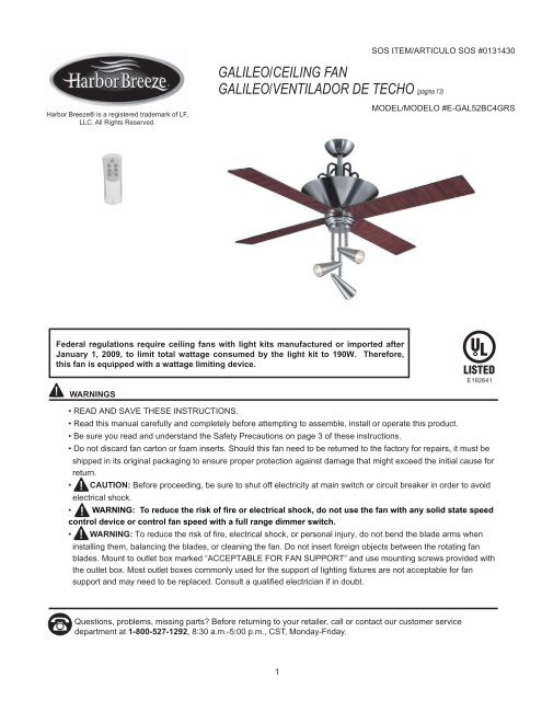
SOS ITEM/ARTICULO SOS #0131430<strong>GALILEO</strong>/<strong>CEILING</strong> <strong>FAN</strong><strong>GALILEO</strong>/<strong>VENTILADOR</strong> <strong>DE</strong> <strong>TECHO</strong> (página 13)Harbor Breeze® is a registered trademark of LF,LLC. All Rights Reserved.MO<strong>DE</strong>L/MO<strong>DE</strong>LO #E-GAL52BC4GRSFederal regulations require ceiling fans with light kits manufactured or imported afterJanuary 1, 2009, to limit total wattage consumed by the light kit to 190W. Therefore,this fan is equipped with a wattage limiting device.E192641WARNINGS• READ AND SAVE THESE INSTRUCTIONS.• Read this manual carefully and completely before attempting to assemble, install or operate this product.• Be sure you read and understand the Safety Precautions on page 3 of these instructions.• Do not discard fan carton or foam inserts. Should this fan need to be returned to the factory for repairs, it must beshipped in its original packaging to ensure proper protection against damage that might exceed the initial cause forreturn.• CAUTION: Before proceeding, be sure to shut off electricity at main switch or circuit breaker in order to avoidelectrical shock.• WARNING: To reduce the risk of fire or electrical shock, do not use the fan with any solid state speedcontrol device or control fan speed with a full range dimmer switch.• WARNING: To reduce the risk of fire, electrical shock, or personal injury, do not bend the blade arms wheninstalling them, balancing the blades, or cleaning the fan. Do not insert foreign objects between the rotating fanblades. Mount to outlet box marked “ACCEPTABLE FOR <strong>FAN</strong> SUPPORT” and use mounting screws provided withthe outlet box. Most outlet boxes commonly used for the support of lighting fixtures are not acceptable for fansupport and may need to be replaced. Consult a qualified electrician if in doubt.Questions, problems, missing parts? Before returning to your retailer, call or contact our customer servicedepartment at 1-800-527-1292, 8:30 a.m.-5:00 p.m., CST, Monday-Friday.1
TABLE OF CONTENTSSafety Information .....................................................................................................................................................3Package Contents………………………..…………………………………………………………………………………..4Preparation…………………………………..….…………………..……………………….…………….………………..5Initial Installation …………………………………..…………………………………………………………..………………..5Fan Mounting.........................……………………………………………………….………………………….........6Wiring .........................................................................................................................................................................6Final Installation …………………………….…………….……………………….…………….……………………......7 - 9Remote Control Operation...........……………………………………………..………………………............................9Automated Learning Process/Activating Code .........................................................................................................10Bulb Replacement for Up-light ................................................................................................................10Care and Maintenance……………………………………………………………………………..……......................10Troubleshooting…………………………...........................................................................................…….............11Warranty…………………………………………………….……………………………………………........................122
SAFETY INFORMATIONREAD AND SAVE THESE INSTRUCTIONSPlease read and understand this entire manual before attempting to assemble, install or operate the product. If youhave any questions regarding the product, please call customer service at 1-800-527-1292, 8:30 a.m.-5:00 p.m.,CST, Monday-Friday.1. Before you begin installing the fan, disconnect the power by removing fuses or turning off circuit breakers.2. CAUTION: Read all instructions and safety information before installing your new fan. Review theaccompanying assembly diagrams.3. CAUTION: To avoid personal injury, the use of gloves may be necessary while handling fan parts withsharp edges.4. Make sure that all electrical connections comply with local codes, ordinances, the National Electrical Code andANSI/NFPA 70-1999. Hire a qualified electrician or consult a do-it-yourself wiring handbook, available at <strong>Lowe's</strong>, ifyou are unfamiliar with installing electrical wiring.5. Make sure the installation site you choose allows a minimum clearance of 7 feet from the blades to the floor and atleast 30 in. from the end of the blades to any obstruction.6. WARNING: To reduce the risk of fire, electrical shock, or personal injury, mount fan to outlet box marked"ACCEPTABLE FOR <strong>FAN</strong> SUPPORT" and use mounting screws provided with the outlet box. Most outlet boxescommonly used for the support of lighting fixtures are not acceptable for fan support and may need to be replaced.Consult a qualified electrician if in doubt. Secure the outlet box directly to the building structure. The outlet box andits support must be able to support the moving weight of the fan (at least 35 lbs.). Do NOT use a plastic outlet box.7. After you install the fan, make sure that all connections are secure to prevent the fan from falling.8. WARNING: To reduce the risk of fire, electrical shock, or personal injury, wire connectors provided with thisfan are designed to accept only one 12 gauge house wire and two lead wires from the fan. If your house wire islarger than 12 gauge or there is more than one house wire to connect to the two fan lead wires, consult anelectrician for the proper size wire connectors to use.9. WARNING: To reduce the risk of fire or electrical shock, do not use the fan with any solid state speedcontrol device or control fan speed with a full range dimmer switch.10. WARNING: To reduce the risk of fire, electrical shock, or personal injury, do not bend the blade arms wheninstalling them, balancing the blades, or cleaning the fan. Do not insert objects between the rotating fan blades.11. WARNING: To reduce the risk of personal injury, use only parts provided with this fan. The use of partsOTHER than those provided with this fan will void the warranty.12. The net weight of this fan including the light kit is: 23.55 lbs. (10.68 kg).3
PACKAGE CONTENTSPart Description QuantityA Downrod 1B Canopy 1C Mounting Bracket 1D Scroll iron 4E* Motor Housing 1F Light Kit Fitter 1G* Candelabra Base Bulb 4(pre-installed in motor housing)H Blade 4I 3/16 Blade Screw (in hardware pack) 12J Blade Washer (in hardware pack) 12K E3 Wire Connector (4 in regular hardware pack; 106 in remote control hardware pack)L Canopy Mounting Screw (attached to mounting bracket) 2M Pin (in motor housing yoke) 1N Clip (attached to pin) 1O* 1.5-volt (AA) Battery (in hardware pack) 2P Remote Control Transmitter 1Q Cap (in hardware pack) 1R* Halogen Bulb (for light kit) 3S Canopy Cover (in hardware pack) 1A B CD E FGHI J KIMPORTANT REMIN<strong>DE</strong>R: You must usethe parts provided with this fan for properinstallation and safety.L M NO P QRSNOTE:For replacement parts, call our customer service departmentat 1-800-527-1292, 8:30 a.m.-5:00 p.m., CST, Monday-Friday.When ordering parts, please have the Model # or Item # of thefan available, which can be found on page 1.* The parts denoted with an asterisk (*) above are NOTreplaceable.4
PREPARATION1. Before beginning assembly and installation of product, make sure all parts are present. Compare parts with“Package Contents” list and diagrams on the previous page. If any part is missing or damaged, do not attempt toassemble, install or operate the product. Contact customer service for replacement parts as indicated at the bottomof page 4.Estimated Assembly Time: 120 minutesTools Required for Assembly (not included): electrical tape, Phillips screwdriver, pliers, safety glasses, stepladderand wire strippersHelpful Tools (not included): AC tester light, tape measure, do-it-yourself-wiring handbook, available at Lowe’s, andwire cuttersBulbs Required (included): 4 candelabra base 15-watt max. bulbs, for up-light3 halogen 50-watt max. bulbs, size GU10, for light kitDANGER: When using an existing outlet box, make sure the box is securely attached to the building structureand can support the full weight of the fan. Failure to do this can result in serious injury or death. The stability of theoutlet box is essential in minimizing wobble and noise in the fan after installation is complete.CAUTION: Be sure outlet box is properly grounded and that a ground wire (green or bare) is present.2. After opening top of carton, remove mounting hardware package from foam inserts. Remove motor from packingand place on carpet or on foam to avoid damage to finish.CAUTION: Carefully check all screws, bolts and nuts on fan motor assembly to ensure that they are secured.INITIAL INSTALLATION1. Turn off circuit breakers and wall switch to the fan supply line leads.(Fig. 1)DANGER: Failure to disconnect power supply prior to installationmay result in serious injury or death.Fig. 12. Determine mounting method to use. (Fig. 2)A. Normal mountB. Angle mountIMPORTANT: If using the angle mount, check to make sure theceiling angle is not steeper than 19°.AFig. 2B3. Check to make sure blades (H) are at least 30 in. from anyobstruction. Check downrod (A) length to ensure blades (H) are atleast 7 ft. above the floor. (Fig. 3)7 ft.min.H30 in.min.4. Secure mounting bracket (C) to outlet box using screws, springwashers, and flat washers provided with the outlet box. (Fig. 4)*Note: It is very important that you use the proper hardware wheninstalling the mounting bracket (C) as this will support the fan.IMPORTANT: If using the angle mount, make sure open end ofmounting bracket (C) is installed facing the higher point of the ceiling.Fig. 3C5Fig. 4
<strong>FAN</strong> MOUNTING1. Remove pin (M) and clip (N) from motor housing yoke at top of motorhousing (E) and partially loosen set screws. (Fig. 1)*Helpful Hint: Downrod style mounting is best suited for ceilings 8 ft.(2.44 m) high or higher. For taller ceilings you may want to use a longerdownrod (sold separately) than the one provided. Angle style mountingis best suited for angled or vaulted ceilings. A longer downrod issometimes necessary to ensure proper blade clearance.Fig. 1NMSetScrewE2. Insert downrod (A) through canopy (B) and canopy cover (S). [Note:Canopy cover (S) must be turned with the shiny side toward the motorhousing (E).] Thread wires from motor housing (E) through downrod (A).(Fig. 2)Fig. 2ABSA3. Slip downrod (A) into motor housing yoke, align holes and re-install pin(M) and clip (N). Re-tighten set screws in motor housing yoke and thentighten nuts. (Fig. 3)NMEFig. 34. Install ball end of downrod (A) into mounting bracket (C)opening. Align slot in ball with tab in mounting bracket (C). (Fig. 4)DANGER: Failure to align slot in ball with tab may result inserious injury or death.Fig. 4BallCABWIRINGWARNING: To reduce the risk of fire, electrical shock, orpersonal injury, wire connectors provided with this fan are designedto accept only one 12 gauge house wire and two lead wires from thefan. If your house wire is larger than 12 gauge or there is more thanone house wire to connect to the two fan lead wires, consult anelectrician for the proper size wire connectors to use.CAUTION: Be sure outlet box is properly grounded and that aground (green or bare) wire is present.WARNING: If house wires are different colors than referred toin the following steps, stop immediately. A professional electricianis recommended to determine wiring.6
WIRING1. [NOTE: For each wire connection below, and use one of thewire connectors (K) provided, making sure to screw wireconnector (K) on in a clockwise direction.]Connect BLACK wire from fan to BLACK wire from ceiling.Connect WHITE wire from fan to WHITE wire from ceiling.Connect all GROUND (GREEN) wires together from fan (ondownrod and mounting bracket) to BARE/GREEN wire fromceiling. (Fig. 1)Fig. 1120 V PowerFROM<strong>CEILING</strong><strong>FAN</strong>BLACKWHITEGROUND/GREEN (BARE)WHITEGREENBLACKNote: Black wire is hot power for fan. White wire is common forfan and light kit. Green or bare wire is ground.GREENWHITEFROM <strong>FAN</strong>2. Wrap electrical tape around each individual wire connector (K)down to the wire as shown in Fig. 2.KWARNING: Make sure no bare wire or wire strands arevisible after making connections. Place green and whiteconnections on opposite side of box from the black connections.KKTurn spliced/taped wires upward and gently push wires and wireconnectors (K) into outlet box.Fig. 2IMPORTANT: Using a full range dimmer switch to control fanspeed will cause a loud humming noise from fan. To reduce therisk of fire or electrical shock, do NOT use a full range dimmerswitch to control fan speed. (Fig. 3)DimmerSwitchFor illustrative purposes only--notintended to cover all types of controlsFig. 3FINAL INSTALLATION1. Locate two canopy mounting screws (L) on underside ofmounting bracket (C) and remove screw (L) closest to the openend of the hanging bracket (C). Partially loosen the other screw(L). Lift canopy (B) to mounting bracket (C). Place rounded partof slotted hole in canopy (B) over loosened screw (L) in hangingbracket (C) and push up. Twist canopy (B) to lock. Re-insertscrew (L) that was removed, and then tighten both screws (L)securely. Slide canopy cover (S) up to canopy (B), aligningrounded part of slotted holes in canopy cover (S) withscrewheads in bottom of canopy (B). Turn canopy cover (S) tothe right (clockwise) until it stops. (Fig. 1)Fig. 1ALBS7
FINAL INSTALLATION2. Locate the motor housing screws pre-installed in the top of themotor housing (E) and remove screws with a Phillips screwdriver.Align holes in scroll iron (D) with screw holes in top of motorhousing (E). Re-install motor housing screws that were previouslyremoved and securely tighten screws. (Fig. 2)Repeat procedure for remaining scroll irons (D).DMotorHousingScrews<strong>DE</strong>Fig. 23. Remove cardboard pieces from between fitter plate and bladeband.TIP: Use of a magnetic tip screwdriver is recommended.Locate 12 blade screws (I) and blade washers (J) in hardwarepack. Blade washers (J) for blade screws (I) can be set on eachblade screw (I) prior to installing blades (H).Slide blade (H) through one of the narrow, rectangular openings onblade band, aligning holes in blade (H) with holes located insidemotor housing (E). [Note: Turn blade band in order to align/insertblade screws (I) and blade washers (J).] Insert three blade screws(I), along with blade washers (J), and then tighten blade screws (I)securely with a Phillips screwdriver. (Fig. 3) Repeat procedure foreach remaining blade (H).BladeBandFig. 3JIEHFitter Plate4. Remove three screws from fitter plate on underside of motorhousing (E). (Fig. 4)Connect female plug in the receiver to male plug from motorhousing (E). Make sure plugs connect tightly. Connectantenna wire that extends from fitter plate to antenna wire fromreceiver. Make sure molex connections on these two wiresconnects tightly. (Fig. 4)Fitter PlateEAntenna WireMale PlugFemale PlugAlign holes in light kit fitter (F) with holes in fitter plate.Re-install three screws that were previously removed. Tightenscrews securely with a Phillips screwdriver. (Fig. 4)ReceiverFig. 4F8
FINAL INSTALLATION5. Install three 50-watt max. halogen bulbs (R) included. (Fig. 5)IMPORTANT: When replacing bulbs, allow bulbs and light kit tocool before touching them.FRFig. 5REMOTE CONTROL OPERATIONOperation buttons on the panel of the transmitter (P):HI buttonMED buttonLOW buttonOFF buttonUP buttonDOWN buttonREV buttonfor fan HIGH speedfor fan MEDIUM speedfor fan LOW speedfor turning fan OFFfor light ON/OFF, upper lightfor light BRIGHTNESS and OFF, lower lightto REVERSE blade direction (fan must be onlow before reversing blade direction)PThe light function is controlled by pressing the UP and/or DOWN button.Tap either UP or DOWN button quickly to turn lights off or on. HoldDOWN button down to increase or decrease lights. If you press DOWNbutton in excess of 0.7 seconds it becomes a dimmer. The lights varycyclically in 0.8 seconds. The DOWN light button has an auto resumefunction which keeps the lights at the same brightness as the last timethey were turned off.9
DIM ON/OFFAUTOMATED LEARNING PROCESS/ACTIVATING CO<strong>DE</strong>CAUTION: The remote control transmitter (P) can be programmedto multiple receivers or fans. If this is not desired, turn wall switchoff to any other programmable receiver or fan.1. Locate the two batteries (O) and then remove plastic that iswrapped around batteries (O). Remove battery cover from backside of transmitter (P). Install the two 1.5-volt (AA) batteries (O)provided--(refer to drawing at right).PO2. Locate dimmer switch in the top left part of the batterycompartment labeled “DIM”. (refer to drawing at right) Set dimmerswitch to the “ON” position. [Note: If you prefer not to havedimming capability, set dimmer switch to “OFF” position.]3. Restore electrical power. Within 60 seconds of restoringelectrical power, press the “LEARN” button in the batterycompartment (refer to drawing at right) for 5 seconds or until fanswitches to MEDIUM speed. Test the light and fan functions toconfirm the learning process is complete.4. Replace battery cover on transmitter (P)--refer to drawing atright.IMPORTANT: To prevent damage to remote control transmitter(P), remove the batteries (O) if not used for long periods. Store thetransmitter (P) away from excess heat or humidity.LEARNDIM ON/OFFLEARNBatteryCoverBULB REPLACEMENT FOR UP-LIGHTIMPORTANT: The motor housing (E), as well as thebulbs (G) themselves, can become extremely hot whenthe light has been on; therefore, please allow sufficienttime for motor housing (E) and bulbs (G) to cool downbefore touching.Replace burnt-out bulb (G) with one candelabra base15-watt max. bulb. Repeat for each burnt-out bulb (G).GECARE AND MAINTENANCEAt least twice each year, lower canopy (B) to check downrod (A) assembly, and then tighten all screws on the fan.Clean motor housing (E) with only a soft brush or lint-free cloth to avoid scratching the finish. Clean blades (H)with a lint-free cloth. You may occasionally apply a light coat of furniture polish to wood blades for addedprotection.IMPORTANT: Shut off main power supply before beginning any maintenance. Do not use water or a damp clothto clean the ceiling fan.10
TROUBLESHOOTINGWarning: Before beginning work, shut off the power supply to avoid electrical shock.Problem Possible Cause Corrective ActionFan does not move. 1. Power is off or fuse is blown. 1. Turn power on or check fuse.2. Faulty wire connection. 2. Turn power off. Loosen canopy(B) and check all connections.3. Plugs and/or antenna wire not 3. Check that male and female plugsconnected properly.and/or antenna wire in switch housing areconnected properly according toinstructions on page 8.Noisy operation. 1. Blades (H) are loose. 1. Tighten all blade screws (I).2. Cracked blade (H). 2. Replace blade (H).3. Full range dimmer switch. 3. Replace with ON/OFF wall switch only.4. Fan is new. 4. Allow fan a “break in” period of afew days, especially when runningthe fan at Medium and High speeds.Excessive wobbling. 1. Blades (H) are loose. 1. Tighten all blade screws (I).2. Unbalanced blades (H). 2. Switch one blade (H) with ablade (H) from the opposite side.3. Fan not securely mounted. 3. Turn power off. Carefully loosencanopy (B) and verify that mountingbracket (C) is secure.4. Fan too close to vaulted ceiling. 4. Use a longer downrod (A) or move fanto another location.5. Set screw(s) on motor housing 5. Tighten yoke set screw(s) securely.yoke is (are) not tightened properly.6. Set screw on hanging ball is not 6. Carefully loosen and lower screw ontightened properly.canopy (B) and verify that set screw onhanging ball is tightened securely.Fan operates but lights 1. Bulb(s) not installed correctly. 1. Re-install bulb(s).fail (if applicable). 2. Wires in canopy (B) not wired 2. Check wires in canopy (B) and, ifproperly.necessary, re-wire according toinstructions on page 6 and 7.3. Wall switch to fan is off. 3. Make sure that wall switch to fan is on.4. Plugs and/or antenna wire not 4. Check that male and female plugsconnected properly.and/or antenna wire in switch housing areconnected properly according toinstructions on page 8.5. Light kit is lamped with more 5. Lamp light kit with bulbs that total nothan the allowable 190W, causing more than 190W.the wattage limiting device tointerrupt the flow of electricity to the lightkit.Note: A small amount of “wobble” is normal and should not be considered a defect.11
WARRANTYLIMITED LIFETIME WARRANTY: Litex Industries warrants this fan to be free from defects in workmanship andmaterials present at time of shipment from the factory for Lifetime limited from the date of purchase. This warrantyapplies only to the original purchaser. Litex Industries agrees to correct any defect at no charge or, at our option,replace the ceiling fan with a comparable or superior model.To obtain warranty service, present a copy of your sales receipt as proof of purchase. All cost of removal andreinstallation are the express responsibility of the purchaser. Any damage to the ceiling fan by accident, misuse orimproper installation, or by using parts not produced by the manufacturer of this fan or affixing accessories notproduced by the manufacturer of this fan, are the purchaser’s own responsibility. Litex Industries assumes noresponsibility whatsoever for fan installation during the limited lifetime warranty. Any service performed by anunauthorized person will render the warranty invalid.Due to varying climatic conditions, this warranty does not cover changes in brass finish, rusting, pitting, tarnishing,corroding or peeling. Brass finish fans maintain their beauty when protected from varying weather conditions. Anyglass provided with this fan is not covered by the warranty.Any replacement of defective parts for the ceiling fan must be reported within the first year from the date ofpurchase. For the balance of the warranty, call our customer service department (at 1-800-527-1292) for returnauthorization and shipping instructions so that we may repair or replace the ceiling fan. Any fan or parts returnedimproperly packaged is/are the sole responsibility of the purchaser. There is no further express warranty. LitexIndustries disclaims any and all implied warranties. The duration of any implied warranty which cannot bedisclaimed is limited to the limited lifetime period as specified in our warranty. Litex Industries shall not be liable forincidental, consequential or special damages arising at or in connection with product use or performance except asmay otherwise be accorded by law. This warranty gives you specific legal rights and you may also have other rightswhich vary from state to state. This warranty supersedes all prior warranties.12Printed in China
ARTICULO SOS #0131430<strong>GALILEO</strong>/<strong>VENTILADOR</strong> <strong>DE</strong> <strong>TECHO</strong>Harbor Breeze® es marca registrada deLF, LLC. Reservados todos los derechos.MO<strong>DE</strong>LO #E-GAL52BC4GRSEl reglamento federal requiere un ventilador de techo con juego de luz fabricado oimportado después del 1 ro de enero del 2009 limite el vatiaje total que consume el juegode luz a 190W. Por lo tanto, este ventilador tiene un aparato que sirve para limitar elvatiaje.ADVERTENCIASE192641• LEA Y GUAR<strong>DE</strong> ESTAS INSTRUCCIONES.• Lea este instructivo detenida y completamente antes de tratar de ensamblar, instalar o hacer funcionar esteproducto.• Asegúrese de leer y entender la información de seguridad en la página 15 de estas instrucciones.• No deseche la caja del ventilador ni la goma espuma incluida. Si hay que mandar el ventilador a la fábrica poralguna reparación, se debe enviar en su paquete original para asegurar la protección apropiada contra daños quepodrían exceder la causa inicial por la cual se devolvió.• PRECAUCION: Antes de proseguir, desconecte la electricidad, quitando los fusibles o cortando el suministrode energía de los circuitos para evitar un choque eléctrico.• ADVERTENCIA: Para reducir el riesgo de incendio o un choque eléctrico, no use el ventilador conningún control de velocidad de estado sólido ni controle la velocidad del ventilador con un interruptor conreductor de luz de gama completa.• ADVERTENCIA: Para reducir el riesgo de incendio, choque eléctrico o lesión personal, no doble los brazosde las paletas mientras las esté instalando, ni cuando esté balanceando las paletas ni cuando esté limpiando elventilador. No inserte objetos extraños entre las paletas giratorias del ventilador. Sujete a una caja de salidamarcada "Aceptable para sostener ventilador" ("ACCEPTABLE FOR <strong>FAN</strong> SUPPORT" en inglés) y use los tornillosde montaje proporcionados con la caja de salida. La mayoría de las cajas de salida que se usan comúnmente parasostener aparatos de alumbrado no son aceptables para sostener ventiladores y es posible que sea necesarioreemplazarla. Consulte con un electricista calificado si tiene alguna duda.¿Preguntas, problemas, faltan piezas? Antes de regresar a la tienda, llame o póngase en contacto connuestro departamento de servicio al cliente al 1-800-527-1292, de 8:30 a.m. a 5:00 p.m., hora central, de lunesa viernes.13
INDICE <strong>DE</strong> MATERIASInformación de seguridad ..............………………………………………………………………………...……..… 15Contenido del paquete ......................…………………………………………………………………………..……. 16Preparación .....................................................................................................................................................17Instalación inicial............................................……………………………………………….......…......................17Montaje del ventilador ...............................…………………………………………...................................................... 18Conexión de los cables ..................................................................................................................................18 - 19Instalación final .…………………….........................................................................................................19 - 21Funcionamiento del control remoto......................……………............................................................…........21Proceso de aprendizaje automático/El activar el código ....................................................................................22Reemplazo de bombillas de la luz superior ........................................................................................................22Cuidado y mantenimiento ........................……………………………………………………......……………… 22Localización de fallas .....................................…………………………………………..…....……....…......23 - 24Garantía ........................…………………………………….………………………………………….………........... 2414
INFORMACION <strong>DE</strong> SEGURIDADPOR FAVOR LEA Y GUAR<strong>DE</strong> ESTAS INSTRUCCIONESPor favor lea el instructivo entero antes de tratar de ensamblar, instalar o hacer funcionar el producto. Si tienealguna pregunta acerca del producto, por favor llame al servicio al cliente al 1-800-527-1292, de 8:30 a.m. a 5:00p.m., hora central, de lunes a viernes.1. Antes de empezar a instalar el ventilador, desconecte la electricidad, quitando los fusibles o cortando el suministrode energía de los circuitos.2. PRECAUCION: Lea todas las instrucciones y la información de seguridad antes de instalar su ventiladornuevo. Revise los diagramas de ensamblaje acompañantes.3. PRECAUCION: Para reducir el riesgo de daño corporal, es posible que sea necesario usar guantes almanejar las piezas del ventilador que tengan bordes afilados.4. Asegúrese de que todas las conexiones eléctricas cumplen con los códigos y las ordenanzas locales, con elCódigo Nacional Eléctrico (NEC, por sus siglas en inglés), y ANSI/NFPA 70-199. Contrate un electricista calificado oconsulte una guía de instalación eléctrica de hágalo usted mismo, disponible en <strong>Lowe's</strong>, si no está familiarizado conla instalación eléctrica.5. Asegúrese de que el lugar de instalación que usted escogió tiene un mínimo de 2,13 m de desde las paletas hastael piso y que la punta de las paletas quede a por lo menos 76,2 cm de cualquier obstrucción.6. ADVERTENCIA: Para reducir el riesgo de incendio, choque eléctrico o daño corporal, sujete el ventilador auna caja de salida marcada "Aceptable para sostener ventilador" ("ACCEPTABLE FOR <strong>FAN</strong> SUPPORT" en inglés)y use los tornillos de montaje proporcionados con la caja de salida. La mayoría de las cajas de salida que se usancomúnmente para sostener aparatos de alumbrado no son aceptables para sostener ventiladores y es posible quesea necesario reemplazarla. Consulte con un electricista calificado si tiene alguna duda. Asegure la caja de salidadirectamente a la estructura del edificio. La caja de salida y el soporte deben ser capaces de sostener el peso móvildel ventilador (por lo menos 22,7 kg). NO use una caja de salida plástica.7. Después de instalar el ventilador, verifique que todas las conexiones estén seguras para que no se caiga elventilador.8. ADVERTENCIA: Para reducir el riesgo de incendio, choque eléctrico o daño corporal, los conectores paracable provistos con este ventilador son diseñados para aceptar sólo un cable de calibre 12 de la casa y dos cablesprincipales del ventilador. Si el calibre del cable de la casa es superior al 12 o hay más de un cable de la casa paraconectar a los cables principales del ventilador, consulte con un electricista para informarse sobre el tamañocorrecto de conectores para cable que se debe usar.9. ADVERTENCIA: Para reducir el riesgo de incendio o un choque eléctrico, no use el ventilador conningún control de velocidad de estado sólido ni controle la velocidad del ventilador con un interruptor conreductor de luz de gama completa.10. ADVERTENCIA: Para reducir el riesgo de incendio, choque eléctrico o lesión personal, no doble brazos delas paletas mientras las esté instalando, ni cuando esté balanceando las paletas ni cuando esté limpiando elventilador. No inserte objetos entre las paletas giratorias del ventilador.11. ADVERTENCIA: Para reducir el riesgo de lesión personal, use sólo las piezas provistas con esteventilador. Al usar piezas DISTINTAS a las provistas con este ventilador se invalidará la garantía.12. El peso neto del ventilador con el juego de luz es de: 10,68 kg.15
CONTENIDO <strong>DE</strong>L PAQUETEPieza Descripción CantidadA Vástago 1B Cubierta 1C Soporte de montaje 1D Brazo con voluta 4E * Bastidor del motor 1F Conectador para el juego de luz 1G* Bombilla de base candelabro 4(pre-instalada en el bastidor del motor)H Paleta 4I Tornillo para la paleta 4,76 m 12(en paquete de artículos de ferretería)J Arandela para la paleta 12(en paquete de artículos de ferretería)K Conector para cable E3 (4 en paquete de artículos 10de ferretería normal; 6 en paquete de artículos de ferretería del control remoto)L Tornillo para montaje de la cubierta 2(sujetado al soporte de montaje)M Clavija (en el cuello del bastidor del motor) 1N Sujetador (sujetado a la clavija) 1O* Batería de 1,5 voltios (tamaño AA) 2(en paquete de artículos de ferretería)P Transmisor del control remoto 1Q Tapa (en paquete de artículos de ferretería) 1R* Bombilla halógena 3(para el juego de luz)S Decoración para la cubierta 1(en paquete de artículos de ferretería)A B CD E FGHI J KL M NRECORDATORIO IMPORTANTE: Se tienenque utilizar las piezas provistas con este ventiladorpara una instalación adecuada y su seguridad.O P QRSNOTA:Para piezas de repuesto, llame a nuestro departamento deservicio al cliente al 1-800-527-1292, de 8:30 a.m. a 5:00 p.m.,CST, de lunes a viernes. Al pedir piezas, por favor tenga listoel No. de modelo o No. de artículo del ventilador. Estos sepueden encontrar en la página 1 (y la página 13).* NO se pueden pedir de repuesto las piezas señaladas conun asterisco (*) más arriba.16
PREPARACION1. Antes de empezar con el ensamblaje e instalación del producto, asegúrese de tener todas las piezas. Compare laspiezas con la lista y los diagramas del "Contenido del paquete" en la página anterior. Si falta alguna pieza o seencuentra dañada, no trate de ensamblar, instalar o hacer funcionar el producto. Póngase en contacto con eldepartamento de servicio al cliente para piezas de repuesto tal como se le indica al pie de la página 16.Tiempo estimado para la instalación: 120 minutosHerramientas necesarias para el ensamblaje (no incluidas): cinta aislante, destornillador Phillips, alicate, gafasprotectoras, escalera portátil y pela cablesHerramientas opcionales (no incluidas): lámpara probador CA, cinta de medir, guía de instalación eléctrica dehágalo usted mismo, disponible en <strong>Lowe's</strong>, y cortaalambresBombillas necesarias (incluidas): 4 bombillas de base candelabro de 15 vatios máx., para la luz superior3 bombillas halógenas de 50 vatios máx. tamaño GU10, para el juego de luzPELIGRO: Cuando utilice una caja de salida existente, asegúrese de que la caja esté firmemente sujetada ala estructura del edificio para que pueda sostener el peso total del ventilador. El no hacer ésto puede resultar engraves daños o la muerte. La estabilidad de la caja de salida es esencial para minimizar tambaleo y ruido en elventilador una vez que se haya terminado la instalación.PRECAUCION: Asegúrese de que la caja de salida esté conectada a tierra correctamente y que haya unconductor a tierra (cable verde o pelado).2. Después de abrir la parte superior de la caja de cartón, saque el paquete de ferretería para montaje de lasinserciones de goma espuma. Saque el motor del empaquetado y póngalo en la alfombra o sobre la goma espumapara evitar daño al acabado.PRECAUCION: Cuidadosamente verifique que todos los tornillos, los pernos y las tuercas en el motor delventilador están seguros.INSTALACION INICIAL1. Apague todos los cortacircuitos y el interruptor de pared a la línea desuministro de electricidad al ventilador. (Fig. 1)PELIGRO: El no desconectar el suministro de electricidad antes dela instalación puede resultar en daños graves o la muerte.Fig. 12. Determine el método de montaje: (Fig. 2)A. Montaje normalB. Montaje en ánguloIMPORTANTE: Cuando se usa el montaje en ángulo, asegúresede que el ángulo del techo no tenga una inclinación mayor de 19°.AFig. 2B3. Asegúrese de que las paletas (H) del ventilador queden a por lomenos 30 pulgadas (76 cm) de cualquier obstrucción. Verifique lalongitud del vástago (A) para asegurarse de que las paletas (H)queden a por lo menos 7 pies (2,13 m) arriba del nivel del piso. (Fig. 3)2,13 mmin.H76,2 cmmin.4. Asegure el soporte de montaje (C) a la caja de salida con lostornillos, las arandelas de resorte, y las arandelas planas provistoscon la caja de salida. (Fig. 4) *Nota: Es muy importante usar losartículos de ferretería correctos al instalar el soporte de montaje (C)puesto que sirve para sostener el ventilador.Fig. 3CIMPORTANTE: Si usa el montaje en ángulo, asegúrese de instalar elsoporte de montaje (C) con la abertura orientada hacia el punto másalto del techo. Fig. 417
MONTAJE <strong>DE</strong>L <strong>VENTILADOR</strong>1. Quite la clavija (M) y el sujetador (N) del yugo del bastidor delmotor en la parte superior del bastidor del motor (E) y parcialmenteafloje los tornillos de fijación. (Fig. 1)*Consejo útil: El montaje con vástago es más adecuado paratechos de 2,44 m o más altos. Para techos de mayor altura, quizásusted prefiera usar un vástago más largo (a la venta por separado)del provisto. El montaje en ángulo es más adecuado para techos enángulo o abovedados. A veces se necesitará un vástago más largopara asegurar el espacio adecuado para las paletas del ventilador.Fig. 1NMtornillo defijaciónE2. Introduzca el vástago (A) en la cubierta (B) y la decoración para lacubierta (S). [Nota: Se tiene que voltear la decoración para lacubierta (S) para que el lado brillante dé al bastidor del motor (E).]Pase los cables del bastidor del motor (E) por el vástago (A). (Fig. 2)ABFig. 2S3. Coloque el vástago (A) dentro del cuello del bastidor del motor,alinee los agujeros y vuelva a instalar el sujetador (N) y la clavija(M). Vuelva a apretar los tornillos de fijación en el yugo del bastidordel motor y luego apriete las tuercas. (Fig. 3)NAMEFig. 34. Instale el extremo de la bola del vástago (A) en la aberturadel soporte de montaje (C). Alinee la ranura de la bola con lalengüeta del soporte de montaje (C). (Fig. 4)PELIGRO: El no alinear la lengüeta con la ranura de labola puede ser causa de graves daños o de muerte.Fig. 4bolaCABCONEXION <strong>DE</strong> LOS CABLESADVERTENCIA: Para reducir el riesgo de incendio, choqueeléctrico o daño corporal, los conectores para cable provistos coneste ventilador son diseñados para aceptar sólo un cable de calibre12 de la casa y dos cables principales del ventilador. Si el calibre delcable de la casa es superior al 12 o hay más de un cable de la casapara conectar a los cables principales del ventilador, consulte con unelectricista para informarse sobre el tamaño correcto de conectorespara cable que se debe usar.PRECAUCION: Asegúrese de que la caja de salida estéconectada a tierra correctamente y que haya un conductor a tierra(cable verde o pelado).ADVENTENCIA: Si los cables de la casa son de coloresdiferentes a los mencionados en los siguientes pasos, suspenda eltrabajo inmediatamente. Se recomienda que un electricista profesionaldetermine la instalación eléctrica que se debe hacer.18
CONEXION <strong>DE</strong> LOS CABLES1. [NOTA: Para cada conexión de cable que se va a hacer acontinuación, use uno de los conectores para cable (K) provistos,asegurándose de atornillar el conector para cable (K) en el sentido delas agujas del reloj.]Conecte el cable NEGRO del ventilador al cable NEGRO del techo.Conecte el cable BLANCO del ventilador al cable BLANCO deltecho. Conecte todos los CONDUCTORES A TIERRA (cablesVER<strong>DE</strong>S) del ventilador (en el vástago y el soporte de montaje) alcable PELADO/VER<strong>DE</strong> del techo. (Fig. 1)Fig. 1120 V cablesde corriente<strong>DE</strong>L <strong>TECHO</strong><strong>VENTILADOR</strong>NEGROBLANCOTIERRA/VER<strong>DE</strong> (PELADO)VER<strong>DE</strong>NEGROBLANCONota: El cable negro es positivo (conduce energía eléctrica) delventilador. El cable blanco es tanto para el ventilador como para eljuego de luz. El cable verde o pelado es el que hace tierra.VER<strong>DE</strong><strong>DE</strong>L <strong>VENTILADOR</strong>BLANCO2. Ponga cinta aislante en cada conector para cable (K) hasta llegaral cable como se muestra en la Fig. 2.KADVERTENCIA: Asegúrese de que no se vean cables peladosni filamentos después de hacer las conexiones. Coloque lasconexiones verdes y blancas en la caja al lado opuesto de lasnegras.KKVoltee los cables empalmados (que tienen cinta aislante) hacia arribay con cuidado meta los cables y los conectores para cable (K) dentrode la caja de salida.pleta para controlar la velocidad del ventilador. (Fig. 3)Fig. 2IMPORTANTE: El usar un interruptor con reductor de luz de gamacompleta para controlar la velocidad del ventilador causará unzumbido recio en el ventilador. Para reducir el riesgo de incendio ochoque eléctrico, NO use un interruptor con reductor de luz de gamacompleta para controlar la velocidad del ventilador. (Fig. 3)interruptorcon reductorde luzSólo para propósito ilustrativo--nose intenta cubrir todo tipo de controlFig. 3INSTALACION FINAL1. Localice los dos tornillos para montaje de la cubierta (L) en la parteinferior del soporte de montaje (C) y quite el tornillo (L) que estálocalizado más cerca del extremo abierto del soporte de montaje (C).Afloje parcialmente el otro tornillo (L). Eleve la cubierta (B) hasta elsoporte de montaje (C). Ponga la parte redondeada del agujero conranura en la cubierta (B) encima del tornillo (L) aflojado en el soportede montaje (C) y empuje hacia arriba. Gire la cubierta (B) paracerrarla. Vuelva a introducir el tornillo (L) que se quitó, y luego aprietebien ambos tornillos (L). Suba la decoración para la cubierta (S) hastala cubierta (B), alineando la parte redondeada de los agujeros conranura en la parte inferior de la decoración para la cubierta (S) conlas cabezas de tornillo en el fondo de la cubierta (B). Gire ladecoración para la cubierta (S) a la derecha (en el sentido de lasagujas del reloj) hasta que ya no gire. (Fig. 1)Fig. 1ALBS19
INSTALACION FINAL2. Localice los tornillos del bastidor del motor que ya estáninstalados en la parte superior del bastidor del motor (E) yquitarlos con un destornillador Phillips. Alinee los agujeros en elbrazo con voluta (D) con los agujeros en la parte superior delbastidor del motor (E). Vuelva a instalar los tornillos del bastidordel motor que se habían quitado anteriormente y apriete bien lostornillos. (Fig. 2)Repita el procedimiento con los brazos con voluta (D) restantes.Dtornillos delbastidor delmotor<strong>DE</strong>Fig. 23. Quite los pedazos de cartón localizados en medio de la placade conexión y la banda para las paletas.*Consejo útil: Se recomienda usar un destornillador con puntamagnética.Localice 12 tornillos para sujetar las paletas (I) y arandelas paralas paletas (J) en uno de los paquetes de artículos de ferretería.Las arandelas para las paletas (J) se pueden colocar en lostornillos para las paletas (I) antes de instalar las paletas (H).Deslice una paleta (H) por una de las aberturas estrechas yrectangulares en la banda para las paletas, alineando losagujeros en la paleta con los agujeros localizados dentro delbastidor del motor (E). [Nota: Gire la banda para las paletas paraalinear/introducir los tornillos para las paletas (I) y las arandelaspara las paletas (J).] Introduzca tres tornillos para las paletas (I),junto con las arandelas para las paletas (J), y luego apriételosbien con un destornillador Phillips. (Fig. 3) Repita elprocedimiento con cada una de las demás paletas (H).bandapara laspaletasFig. 3JIEHplaca deconexión4. Quite tres tornillos de la placa de conexión en la parte inferiordel bastidor del motor (E). (Fig. 4)EConecte el enchufe hembra del receptor al enchufe macho delbastidor del motor (E). Asegúrese de que se conecten bien losenchufes. Conecte el cable de la antena que viene de la placade conexión al cable de la antena del receptor. Asegúrese deque se conecten bien las conexiones tipo “molex” en dichoscables. (Fig. 4)placa deconexióncable dela antenaenchufemachoenchufehembraAlinee los agujeros en el conectador para el juego de luz (F) conlos agujeros en la placa de conexión. Vuelva a instalar los trestornillos que se quitaron anteriormente. Apriete bien los tornilloscon destornillador Phillips. (Fig. 4)receptorFig. 4F20
INSTALACION FINAL5. Instale las tres bombillas halógenas (R) de 50 vatios máx.incluidas. (Fig. 5)IMPORTANTE: Cuando necesite reemplazar las bombillas, porfavor permita que se enfríen las bombillas y el juego de luz antes detocarlos.FRFig. 5FUNCIONAMIENTO <strong>DE</strong>L CONTROL REMOTOBotones de funcionamiento en el panel del transmisor (P):Botón HIBotón MEDBotón LOWBotón OFFBotón UPBotón DOWNBotón REVpara velocidad ALTA del ventiladorpara velocidad MEDIA del ventiladorpara velocidad BAJA del ventiladorpara APAGAR el ventiladorpara ENCEN<strong>DE</strong>R y APAGAR la luzsuperiorpara controlar la BRILLANTEZ de la luzinferior y para APAGARLApara CAMBIAR la dirección de las aspas(hay que poner el ventilador en posiciónbaja antes de poner el ventilador en reversa)PLa función de la luz se controla oprimiendo los botones de la luz "UP" o"DOWN". Toque el botón rápido para apagar y prender la(s) luz/luces.Oprima el botón “DOWN” y manténgalo oprimido para aumentar y disminuirla brillantez de las luces. Si oprime el botón “DOWN” por más de 0,7segundos se convierte en reductor de luz. El rango de luz cambia de cicloen 0,8 segundos. El botón “DOWN” de la luz tienen una función que permiteque al encender las luces, éstas se encienden automáticamente en labrillantez en la cual las había dejado antes de apagarlas.21
DIM ON/OFFPROCESO <strong>DE</strong> APRENDIZAJE AUTOMATICO/EL ACTIVAR EL CODIGOPRECAUCION: Se puede programar el transmisor del controlremoto (P) para usar con varios receptores o ventiladores. Sino desea hacer esto, apague el interruptor de pared decualquier otro receptor o ventilador programable.1. Localice las dos baterías (O) y luego quite el plástico con elcual están envueltas. Quite la cubierta de la batería de la partede atrás del transmisor (P) e instale las dos baterías (O) de 1,5voltios (tamaño AA) provistas--(refiérase al dibujo al lado).PO2. Localice el interruptor reductor de luz a mano izquierda en laparte superior del compartimento de la batería etiquetado“DIM”. (refiérase al dibujo al lado) Ponga el interruptor reductorde luz en posición “ON” (encendido). [Nota: Si prefiere no tenerfuncionalidad de reductor de luz, ponga el interruptor reductorde luz en posición “OFF” (apagado).]3. Vuelva a conectar la electricidad. Dentro de 60 segundos dehaber conectado la electricidad de nuevo, oprima el botón“LEARN” (aprender) en el compartimento de la batería(refiérase al dibujo al lado) por 5 segundos o hasta que elventilador cambie a la velocidad MEDIA. Ponga a prueba lasfunciones de luz y ventilador para confirmar que se ha acabadoel proceso de aprendizaje.4. Vuelva a poner la tapa de la batería en el transmisor (P)--(refiérase al dibujo al lado).Nota: Para evitar daño al transmisor del control remoto (P)saque la batería (O) si no se usa por un tiempo extendido.Guarde el transmisor (P) lejos del calor excesivo a lahuemedad.LEARNDIM ON/OFFLEARNcubiertade labateríaREEMPLAZO <strong>DE</strong> BOMBILLAS PARA LA LUZ SUPERIORIMPORTANTE: El bastidor del motor (E), y las bombillas (G)también, pueden ponerse sumamente calientes cuando la luz haestado prendida; por lo tanto, por favor permita suficiente tiempopara que se enfríen el bastidor del motor (E) las bombillas (G)antes de tocarlos.GReemplace la bombilla (G) fundida con una bombilla de basecandelabro de 15 vatios máx. Repita este proceso para cadabombilla (G) fundida.ECUIDADO Y MANTENIMIENTOBaje Ia cubierta (B) para inspeccionar el conjunto del vástago (A) por lo menos dos veces al año, y luego aprietetodos los tornillos del ventilador. Limpie el bastidor del ventilador (E) solamente con un cepillo suave o un pañoque no tenga pelusa para no rayar el acabado. Limpie las paletas (H) con un paño que no tenga pelusa. De vezen cuando usted puede lustrar las paletas de madera con un poco de cera para muebles como una protecciónadicional.IMPORTANTE: Apague la fuente principal del suministro de electricidad antes de iniciar cualquier tipo demantenimiento. No use agua ni un paño húmedo para limpiar el ventilador.22
LOCALIZACION <strong>DE</strong> FALLASADVERTENCIA: Antes de empezar cualquier trabajo, corte el suministro de electricidad para evitar un choqueeléctrico.Problema Causa posible Acción correctivaEl ventilador no funciona. 1. No hay electricidad o se ha 1. Conecte la electricidad o inspeccionesaltado un fusible.inspeccione el fusible.2. Conexión de cables defectuosa. 2. Apague la electricidad. Afloje lacubierta (B) e inspeccione todas lasconexiones.4. Los enchufes y/o el cable de la antena 4. Verifique que se conectaron bien losno se conectaron correctamente.enchufes macho y hembra y/o los cablesde la antena en la caja del interruptorsegún las instrucciones en la página 20.Funcionamiento ruidoso. 1. Las paletas (H) están flojas. 1. Apriete todos los tornillos para laspaletas (I).2. Paleta (H) rota. 2. Reemplace la paleta (H).3. Interruptor con reductor de luz 3. Reemplace el control sólo con unde gama completa.interruptor de pared de apagado yencendido.4. El ventilador es nuevo. 4. Permita unos días para que el motordel ventilador se equilibre,epecialmente al usar el ventilador avelocidad media o alta.Tambaleo excesivo. 1. Las paletas (H) están flojas. 1. Apriete todos los tornillos para laspaletas (I).2. Las paletas (H) no están 2. Intercambie una paleta (H) con otraequilibradas.otra paleta (H) del lado contrario.3. El ventilador no está sujetado 3. Apague la electricidad. Afloje labien.cubierta (B) cuidadosamente yverifique que el soporte de montaje (C)esté bien sujeto.4. El ventilador está demasiado 4. Utilice un vástago (A) más largocerca de un techo abovedado.o mueva el ventilador a otro lugar.5. No se apretó (apretaron) bien el 5. Apriete bien el (los) tornillo(s) de(los) tornillo(s) de fijación en elfijación.yugo del bastidor del motor.6. No se apretó bien el tornillo de 6. Afloje la cubierta (B) y bájelafijación en la bola que sirve paracuidadosamente y verifique quecolgar.esté bien apretado el tornillo defijación a en la bola que sirve paracolgar.El ventilador funciona 1. No se instalaron bien las 1. Instale las bombillas de nuevo.pero las luces no (si aplica). bombillas.2. No se conectaron correctamente 2. Verifique que se conectaron bien loslos cables en la caja de salida.cables en la cubierta (B), y si esnecesario, vuelva a conectarlos según lasinstrucciones en las páginas 18 y 19.3. El interruptor de pared para el 3. Asegúrese de que el interruptor deventilador está apagado.pared para el ventilador esté prendido.4. Los enchufes y/o el cable de la antena 4. Verifique que se conectaron bien losno se conectaron correctamente.enchufes macho y hembra y/o los cablesde la antena en la caja del interruptorsegún las instrucciones en la página 20.23
LOCALIZACION <strong>DE</strong> FALLASProblema (cont.) Causa posible (cont.) Acción correctiva (cont.)[El ventilador funciona pero 5. El juego de luz sobrepasa los 5. Ponga bombillas en el juego delas luces no, (cont.)] 190W permitidos, haciendo que se luz que suman no más de 190W.interrumpa la corriente eléctricaque va al juego de luz debido alaparato que sirve para limitar elvatiaje.Nota: Un pequeño “tambaleo” es normal y no se debe considerar como defecto.GARANTIAGARANTIA LIMITADA <strong>DE</strong> POR VIDA: Litex Industries garantiza que este ventilador está libre de defectos de manode obra y de materiales desde la fecha de salida de la fábrica por el tiempo de por vida limitada a partir de la fechade compra. Esta garantía sólo se aplica al comprador original. Litex Industries se compromete a corregir cualquierdefecto libre de cargo o, si lo considera necesario, a reemplazar el ventilador por un modelo equiparable o superior.Para recibir servicio durante el período de garantía, debe presentar una copia del recibo como comprobante decompra. Cualquier costo derivado de la remoción y la re-instalación será responsabilidad explícita del comprador.Cualquier daño accidental al ventilador o por uso inadecuado o instalación incorrecta o por usar piezas noproducidas por el fabricante de este ventilador o por la fijación de accesorios no producidos por el fabricante deeste ventilador, será la responsabilidad del comprador. Litex Industries no se hace responsable en ningún modo dela instalación del ventilador durante el período de garantía limitada de por vida. Cualquier servicio prestado por unapersona no autorizada invalida la garantía.Debido a los distintos tipos de condiciones climáticas, esta garantía no cubre ningún cambio en el acabado bronce,ni por la oxidación, marcas, la decoloración, la corrosión ni el descascarillado del material. Se conserva la bellezade un ventilador con acabado bronce protegiéndolo de las diversas condiciones de clima. Las pantallas provistascon el ventilador no están cubiertas por la garantía.Cualquier pieza defectuosa del ventilador de techo se debe reportar dentro del primer año desde la fecha decompra. Si desea que reparemos o reemplacemos su ventilador, llame a nuestro departamento de servicio alcliente al (1-800-527-1292) para obtener una autorización de devolución e instrucciones de envío. Cualquierventilador o pieza devuelta en malas condiciones de empaquetamiento será la responsabilidad única delcomprador. No existe ninguna otra garantía expresa. Litex Industries rehusa cualquier y toda garantía implícita. Laduración de cualquier garantía implícita a la que no se pueda renunciar se limita al tiempo de por vida especificadoen nuestra garantía limitada. Litex Industries no es responsable de daños incidentales, emergentes ni especialessurgidos de o con respecto al uso o el funcionamiento del producto, salvo previo acuerdo con la ley. Esta garantíale da derechos legales específicos y es posible que usted también tenga otros derechos que pueden variar deestado en estado. Esta garantía reemplaza toda garantía previa.24Impreso en China