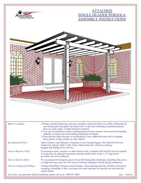
attached single header pergola assembly instructions
attached single header pergola assembly instructions
attached single header pergola assembly instructions

You also want an ePaper? Increase the reach of your titles
YUMPU automatically turns print PDFs into web optimized ePapers that Google loves.
HEADER SPLICE (OPTIONAL)-If the <strong>header</strong> is in two or more pieces, insert an equal amount of the provided <strong>header</strong> splice into each of the square ends of the<strong>header</strong>s and secure as shown using (12) #8 x 3/4" HWH #2 Tek Screws (see Fig. S-1).-Be sure to place a post under the splice (see Fig. S-2).Header SpliceHeader#8 x 3/4" HWH #2 Tek ScrewFig. S-1Fig. S-2LATTICE SPLICE (OPTIONAL)-If the lattice is in two or more pieces, insert a lattice splice into the ends of two tubes and secure with (2) #8 x 3/4" HWH#2 Tek screws (see Fig. S-3).#8 x 3/4" HWH #2 Tek ScrewLattice SpliceLattice TubeFig. S-3
STEP 1-Determine the location for your <strong>pergola</strong> and mark the outer edges by snapping a chalk line the length of the <strong>header</strong>s along theouter edge. Turn 90 degrees and snap a chalk line the length of your rafters beginning at the end of the previous chalk line.Repeat to close the square.-Locate the center of the posts by subtracting the desired overhang from the overall dimensions and snap four chalk linesaccordingly (see Fig. 1-1). NOTE: If drawings were received with your order, use those as the guide.NOTE: If installing fiberglass columns, skip to Step 4 now and return to this step later.-Depending on the available surface or local building codes, there are three post mounting options.Option 1 - If your <strong>pergola</strong> has the standard post mounting brackets, anchor them at the intersection of two centerlines bydrilling (4) 3/8" diameter holes and embedding (4) lag screw inserts. Then, attach the brackets to the surface using (4)1/4" x 1 1/2" lag screws or appropriate anchors. Attach a post to each bracket using (4) #12 x 1 1/4" HWH #5 Tek screws(see Fig. 1-2).Centerlineof PostsOuter Edge of CoverStructureOption 13" Sq. PostPost1/4" x 1 1/2" Lag Screw(Conc. Anchor if Req'd)Mounting BracketLag Screw Insert(Not Req'd withAnchor Bolts)Fig. 1-1Fig. 1-2#12 x 1 1/4" HWH#5 Tek ScrewOption 2 - If your <strong>pergola</strong> has the heavy duty mounting brackets, anchor them at the intersection of two centerlines by drilling(4) holes for anchor bolts (not included, hole size will vary). Attach the bracket to the surface using (4) appropriate anchorbolts. Attach a post to each bracket using (2) 3/8" x 3 1/2" bolts (see Fig. 1-3). NOTE: If installing post side plates, only onebolt is required for the post to bracket connection. Run the bolt the same direction the <strong>header</strong> will run.Option 3 - If you plan to bury the posts, start by digging a hole approximately 12" diameter and 30" deep. Place rock 6" deepin the bottom of the hole and drop the post in. Add or remove rocks as necessary to achieve the desired post height aboveground. Fill the hole with a pre-mix of cement, aggregate, and water. Check the post on all sides with a carpenters level tomake sure it is plumb. (see Fig. 1-4). NOTE: Hole size and concrete mix must comply with local building codes.Option 23" Sq. PostOption 33" Sq. PostHeavy DutyMounting BracketGround24" Min.Concrete3/8" x 3 1/2" Boltw/ NutFig. 1-3Anchor BoltFig. 1-4Rubble Stone(used to adjustpost height priorto addingconcrete)
STEP 2-Calculate Distance A using the formula shown in Fig. 2-1. Subtract one from the number of rafters and multiply that by thecenter to center spacing of the rafters. Subtract that from the length of the <strong>header</strong> and divide by two.EXAMPLE: You received a 10'-0" long <strong>header</strong> and five rafters. The standard rafter spacing is 24" on center.5 - 1 = 4; 4 x 24 = 96; 120 - 96 = 24; 24 / 2 = 12; Therefore, Distance A = 12".-Once you know Distance A for your project, position a rafter mounting bracket with Distance A between the end of the<strong>header</strong> and the center of the bracket (see Fig. 2-1).-Attach the bracket to the seam side of the <strong>header</strong> using (4) #8 x 3/4" HWH #2 Tek screws (see Fig. 2-2).NOTE: If the <strong>header</strong> is reinforced with a beam inside, #12 x 1 1/4" HWH #5 Tek screws must be used instead.-Position the next rafter mounting bracket with the rafter spacing between the centers of the two brackets and attach as shown.-Repeat for all rafter mounting brackets.#8 x 3/4" HWH#2 Tek ScrewRafter MountingBracketHeaderRafter Mounting BracketDist. A =Length of Header - [(# of Rafters - 1) x Rafter Spacing]2Fig. 2-1 Fig. 2-2Header-Mark the proper location for the post top brackets by calculating Distance B as shown in Fig. 2-3. Be sure that the spacingbetween the brackets <strong>attached</strong> to the <strong>header</strong> is equal to the spacing between the posts <strong>attached</strong> to the ground.-If you received a column wrap kit with your <strong>pergola</strong>, attach the column plate to the <strong>header</strong> at the same location the post topbracket will be <strong>attached</strong> using (4) #8 x 3/4" HWH #2 Tek screws as shown (see Fig. 2-4).-If you received the standard post top bracket, attach each to the <strong>header</strong> at the proper locations using (12) #8 x 3/4" HWH#2 Tek screws as shown (see Fig. 2-4a).-If you received the optional post top bracket, attach each to the <strong>header</strong> at the proper locations using (4) #12 x 1 1/4" HWH#5 Tek screws as shown (see Fig. 2-4b).HeaderFig. 2-4aRafter Mounting BracketPost Top BracketFig. 2-4bHeaderPost TopBracket#8 x 3/4" HWH#2 Tek ScrewsHeaderFig. 2-3Dist. B =Length of Header - Post Spacing2#8 x 3/4" HWH#2 Tek Screws#12 x 1 1/4" HWH#5 Tek ScrewsColumn Plate(Only w/ Wrap Kit)Post Top Bracket
STEP 3-Hoist the <strong>header</strong> <strong>assembly</strong> to the top of the posts and insert the post top brackets into the top of each post (see Fig. 3-1).-Secure the <strong>header</strong> <strong>assembly</strong> to each post using (4) #12 x 1 1/4" HWH #5 Tek screws per bracket (see Fig. 3-2).NOTE: This applies to both post top bracket types.Header AssemblyHeader Assembly#12 x 1 1/4" HWH#5 Tek Screw3" Sq. Post3" Sq. PostFig. 3-1 Fig. 3-2STEP 4 - OPTIONAL COLUMN KITS: SIDE PLATES-If your <strong>pergola</strong> has side plates, center two per post in front of the post along the <strong>header</strong> (see Fig. 4-1).-Attach the inside face of the side plate to the post using #12 x 1 1/4" HWH #5 Tek screws through the pre-drilled holes.-Also attach the side plate to the <strong>header</strong> at the top using (4) #12 x 1 1/4" HWH #5 Tek screws (see Fig. 4-2).-Insert a hole plug into all exposed holes.-Repeat for each side plate.Header AssemblyHeaderAssemblySide PlateHole Plug#12 x 1 1/4" HWH#5 Tek ScrewSide Plate3" Sq. PostFig. 4-1 Fig. 4-2
STEP 4 - OPTIONAL COLUMN KITS: SQUARE WRAP KIT-Snap two column sections together by fitting the tongues into the grooves and lightly tapping with the heel of your hand.-Once two sets of sections are locked together, stand them on end and snap the open ends together around a post (see Fig. 4-3).-Anchor the bottom of the column with two lower column brackets, (6) lag screw inserts, (6) 1/4" x 1 1/2" lag screws into thesurface, and (6) #8 x 3/4" HWH #2 Tek screws into the column (see Fig. 4-4).3" Sq. PostColumnSectionColumnFig. 4-3 Fig. 4-41/4" x 1 1/2" Lag ScrewLag Screw InsertLower Column Bracket#8 x 3/4" HWH #2 Tek Screw-Once the column sections are secure, assemble a column cap around the bottom of the column.-Attach the column cap to the column using (6) #8 x 3/4" HWH #2 Tek screws as shown (see Fig. 4-5).-Assemble another column cap around the top of the column.-Push the column cap up until flush with the bottom of the <strong>header</strong> and attach to the column plate using (4) #8 x 3/4" HWH#2 Tek screws (see Fig. 4-6).-Attach the column cap to the column using (6) #8 x 3/4" HWH #2 Tek screws as shown (see Fig. 4-6).ColumnHeader AssemblyColumn Plate#8 x 3/4" HWH#2 Tek ScrewColumn CapColumn CapColumn#8 x 3/4"HWH #2Tek ScrewFig. 4-5 Fig. 4-6
STEP 4 - OPTIONAL COLUMN KITS: ROUND WRAP KIT-Snap two column sections together by fitting the tongues into the grooves and lightly tapping with the heel of your hand.-Stand the sections on end and snap the open ends together around a post (see Fig. 4-7).-Anchor the bottom of the column with three lower column brackets, (3) lag screw inserts, (3) 1/4" x 1 1/2" lag screws into thesurface, and (3) #8 x 3/4" HWH #2 Tek screws into the column (see Fig. 4-8).3" Sq. PostColumnSectionColumnFig. 4-7 Fig. 4-81/4" x 1 1/2" Lag ScrewLag Screw InsertLower Column Bracket#8 x 3/4" HWH #2 Tek Screw-Once the column sections are secure, assemble a column cap around the bottom of the column.-Attach the column cap to the column using (6) #8 x 3/4" HWH #2 Tek screws as shown (see Fig. 4-9).-Assemble another column cap around the top of the column.-Push the column cap up until flush with the bottom of the <strong>header</strong> and attach to the column plate using (4) #8 x 3/4" HWH#2 Tek screws (see Fig. 4-10).-Attach the column cap to the column using (6) #8 x 3/4" HWH #2 Tek screws as shown (see Fig. 4-10).Header AssemblyColumnColumn Plate#8 x 3/4" HWH#2 Tek ScrewColumn CapColumn CapColumn#8 x 3/4"HWH #2Tek ScrewFig. 4-9 Fig. 4-10
STEP 4 - OPTIONAL COLUMN KITS: FIBERGLASS COLUMNNOTE: Before installation, fiberglass columns must be painted. See below for color matching formulas.TIP: Before painting, sand the column lightly with 120 grit or finer wet/dry sandpaper. Use mineral sprits to remove all dust/dirt.-Start by measuring the required height of the column. If needed, trim off the bottom of the column.-Cut a notch on opposite sides at the top of the column 3" wide and 2" deep (see Fig. 4-11). This is to allow room to attachthe post to the post top bracket. The notches will be covered by the column cap.-Slip the top and base column caps on the column. The top column cap may rest on the neck mold.-Place the post inside the column and mark the exact mounting location. Apply construction adhesive on the ground in thearea the bottom column cap will be. Continue with the proper option, depending of post mounting method.Column3"2"Top Column CapNeck TrimBottom Column Cap3" Sq. PostTemporarySupportPost MountingBracketColumnFig. 4-11 Fig. 4-12Option 1 - If your <strong>pergola</strong> is surface mounted, anchor the post mounting brackets to the surface as shown in Fig. 1-2 or Fig. 1-3.Prop up the column using any type of support block as show in Fig 4-12. Let the post slide down and attach to the postmounting bracket as shown in Fig. 1-2 or Fig. 1-3. Remove the support blocks and anchor the bottom column cap.Option 2 - If you plan to bury the posts, do so as instructed in Step 1 (see Fig. 1-4). Once posts are installed, hoist the columnover the post and place around it. WARNING: Standard 8'-0" x 8" round fiberglass column weighs approximately 60 pounds;installation may require more than one person. Apply construction adhesive to the bottom surface of the column and anchorthe bottom column cap.-Once columns are installed, continue with installation from Step 2. After the <strong>header</strong> is <strong>attached</strong> (see Step 3), raise the topcolumn cap and attach to the column plate using (4) #8 x 3/4" HWH #2 Tek screws (see Fig. 4-13).Fig. 4-13Header AssemblyColumnColumn Plate#8 x 3/4" HWH#2 Tek ScrewTop Column CapColor Matching FormulasLowes - Valspar Paint 1 gallonExterior/Latex/Semi Gloss/DaylightWhiteBase B1-20015101 - 5 shot103 - 1/2 shot107 - 4 shotAdobe (Clay)Base B1-20036101 (1y oz) - 45 1/2 shot104 (1y oz) - 12 1/2 shot111 (1y oz) - 32 shotWickerBase B1-20015101 - 18 shot107 - 25 1/2 shot109 - 3 1/2 shotLatteBase B1-20015101 - 37 1/2 shot107 (2y oz) - 19 1/2 shot109 - 17 1/2 shot
STEP 5-Begin rafter hanging bracket installation by snapping a level chalk line along the wall to locate the bottom of the rafters.To determine the height of the line, simply add the height of the posts and the height of the <strong>header</strong>.-Locate and mark a centerline on the wall for each rafter hanging bracket adjacent to the rafter mounting brackets on the <strong>header</strong>.-Pre-drill (2) 5/16" holes in the wall, being sure to hit a solid anchor point. Attach a rafter hanging bracket to the wall using(2) 1/4" x 1 1/2" lag screws and lag screw inserts.NOTE: If a solid anchor such as a wall stud can not be located, a ledger board may be required (not supplied by manufacturer).-Attach a rafter seam side up to the bracket using (4) #8 x 3/4" HWH #2 Tek screws (see Fig. 5-1).-Attach the rafters to the rafter mounting brackets using (4) #8 x 3/4" HWH #2 Tek screws per bracket (see Fig. 5-2).Rafter Hanging Bracket#8 x 3/4" HWH #2 Tek ScrewLag Screw InsertHeader1/4" x 1 1/2"Rafter#8 x 3/4" HWHLag Screw#2 Tek Screw Rafter MountingRafterBracketFig. 5-1 Be sure to square brackets with level lineFig. 5-2-After all rafters are installed, layout the lattice tubes on the rafters with the seam side facing up. See Fig. 5-3 for lattice spacingdetails. Similar to how you determined Distance A in Step 2, subtract one from the number of lattice tubes and multiply that bythe center to center spacing of the lattice. Subtract that from the length of the rafter and divide by two.-The standard lattice spacing is 4 1/2" on center. If this is the case for your project, you might have received a short piece of3" square tube. Simply placing this between two lattice tubes will give you the correct lattice spacing.-Once a lattice tube is in the correct position, attach it to each rafter using #10 x 2" sheet metal screws (see Fig. 5-4).LatticeHeaderRafterDist. C =Length of Rafter - [(# of Lattice - 1) x Lattice Spacing]Fig. 5-32LatticeRafter#10 x 2" SMSFig. 5-4