3 TON (6,000 LBS.) JACK STANDS WITH LASER
3 TON (6,000 LBS.) JACK STANDS WITH LASER
3 TON (6,000 LBS.) JACK STANDS WITH LASER

You also want an ePaper? Increase the reach of your titles
YUMPU automatically turns print PDFs into web optimized ePapers that Google loves.
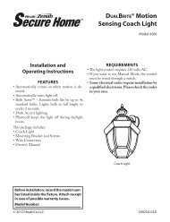
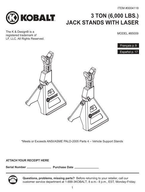
ITEM #<strong>000</strong>41183 <strong>TON</strong> (6,<strong>000</strong> <strong>LBS</strong>.)<strong>JACK</strong> <strong>STANDS</strong> <strong>WITH</strong> <strong>LASER</strong>The K & Design® is aregistered trademark ofLF, LLC. All Rights Reserved.MODEL #85009Français p. 9Español p. 17*Meets or Exceeds ANSI/ASME PALD-2005 Parts 4 – Vehicle Support StandsATTACH YOUR RECEIPT HERESerial NumberPurchase DateQuestions, problems, missing parts? Before returning to your retailer, call ourcustomer service department at 1-888-3KOBALT, 8 a.m.- 8 p.m., EST, Monday-Friday.1
TABLE OF CONTENTSSafety Information .............................................................................................................................. 2Package Contents .............................................................................................................................. 3Preparation Before Use...................................................................................................................... 4Assembly Instructions ........................................................................................................................ 4Operation Instructions ........................................................................................................................ 5Care and Maintenance ....................................................................................................................... 7Warranty............................................................................................................................................. 8Replacement Parts ............................................................................................................................ 8SAFETY INFORMATIONBefore using this product, read this manual and follow all Safety Rules and Operational Instructions.Owner and/or Operator ResponsibilityThe owner and/or operator shall read and comprehend all instructions and warning labels for productand retain them for future reference.OperationThe owner and/or operator shall have an understanding of the product, its operating characteristics,safety precautions and operating instructions before using the jack stands. Safety information shallbe emphasized and understood. If the operator is not fluent in English, the product instructions andsafety recommendations shall be read to and discussed with the operator in the operator's nativelanguage by the purchaser/owner or his designee, making sure that the operator comprehendstheir contents.WARNINGSafety Markings• Study, understand, and follow all instructions, safety precautions and warnings beforeoperating this device• Do not exceed rated capacity• Use only on hard, level surfaces• Center load on saddle• Use a matched pair of jack stands to support one end of a vehicle only• Failure to heed instructions, safety precautions or warnings may result in personal injuryand/or property damageSafety Messages• Jack stands are not to be used to simultaneously support both ends or one side of a vehicle• No alterations shall be made to this product2
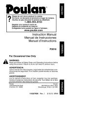
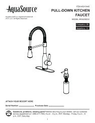
PREPARATION BEFORE USEBefore using this product, make sure all parts are present. Compare parts with package contentslist. If any part is missing or damaged, do not attempt to use the product. Contact customer service.IMPORTANT: ALWAYS Inspect the jack stands before each use.Do not use if bent, broken or cracked components are noted.ASSEMBLY INSTRUCTIONSPost (A) - Face ratchet edge toward the front of base (C).CAUTION: Post is heavy - dropping on hands or feet couldresult in personal injury.Rotate the load locking and release knob (B) to the unlockposition. Place post into the base, press down on post untilpost is completely lowered.CAUTION: Use care when inserting post into base. Keepfingers clear of opening at top of base when inserting post.On side opposite the lift load locking and release knob, bendthe tab in. Make sure tab is completely against base.Repeat steps above to assemble second jack stand.BCAWARNING: Before using the jack stands,check to ensure that the post cannot be pulledout of the base.4
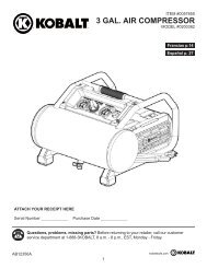
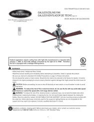
OPERATION INSTRUCTIONSTo Position Jack Stands:1. Place vehicle in PARK (vehicles with automatictransmissions) or in GEAR (vehicles equippedwith standard transmissions) and applyemergency brake.2. Place chocks at front and rear of the vehicle'swheel that will NOT be lifted.3. Raise vehicle to desired height and ensure itis stable.4. Rotate load locking and release knobcounterclockwise to UNLOCK position.5. Extend post to height of axle or flat reinforcedframe surface.6. Make sure both jack stands are at an equalheight and will support the load evenly when thelifting device is removed.7. IMPORTANT: Place jack stands using the lasertargeting device to accurately position saddleunder the support points specified by themanufacturer. DO NOT crawl under the vehiclewhen placing or removing the stands.8. Ensure that the base of both jack stands arepositioned on a hard even surface.9. SLOWLY lower the load on to the jack stands andcheck to ensure the load is located on the centerportion of the saddle located at the top of the post.If load is not located on the center of the saddle orif load is unstable, re-lift the load and reposition thejack stands to ensure proper positioning beforecontinuing with work or repairs.UnlockLaser TargetingDeviceUNLOCKLOCKLoad lockingand release knobLockSaddlePostWARNING: NEVER place your body under the vehicle after the load hasbeen transferred from the jack stands to your lifting device. Doing so could result inserious bodily injury.To Remove Jack Stands:1. Carefully raise vehicle enough to clear the jack stands, making sure the vehicle remains stable.2. Remove jack stands.3. Following instructions provided with your lifting device, carefully lower the vehicle to the ground.To Extend or Retract Post:1. Extend post by gripping saddle and pulling upward while holding base.2. To retract post, rotate load locking and release knob counterclockwise to unlock position.3. Once the load locking and release knob has been rotated to the unlock position, using thumb pushon face of knob to release locking mechanism. The post can be adjusted downward whilepressing the knob.5
OPERATION INSTRUCTIONS (continued)Laser Targeting DeviceThis jack stand has been fitted with a laser targeting device. This device is designed to assist theoperator to properly position the saddle of the jack stand under the load point on the undercarriage ofthe vehicle being lifted.WARNING: Laser targeting devices or pointers are not to be used forentertainment. This device is to be used only as a targeting device to assist theoperator when positioning the jack stands under a vehicle. NEVER point lasertargeting device at anyone's eyes.CAUTION: Use of controls or adjustments or performance ofprocedures other than those specified herein may result inhazardous radiation exposure.CAUTION: The use of optical instruments with this product willincrease eye hazard.CAUTION: Do not attempt to repair or disassemble the laser. Ifunqualified persons attempt to repair this laser product, seriousinjury may result. Any repair required on this laser productshould be performed by authorized service center personnel.AVOID EXPOSURE - Laser radiationis emitted from this apertureD A N G E R<strong>LASER</strong> RADIATIONAVOID DIRECT EYE EXPOSUREMAX. OUTPUT POWER < 5mWWAVELENGTH 630-680 nmCLASS IIIA <strong>LASER</strong> PRODUCTComplies with 21 CFR 1040. 10 and 1040.111. To turn laser targeting device "ON", using indexfinger, push down on rubber retainer cap (A)located in center of the jack stand’s saddle.2. Position jack stand under vehicle to be lifted.3. A target will be projected onto the undercarriageof vehicle.4. To turn laser targeting device "OFF", using indexfinger, push down on rubber retainer cap locatedin the center of jack stand’s saddle.A6
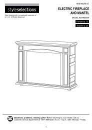
OPERATION INSTRUCTIONS (continued)REMOVE/INSTALL BATTERIES IN <strong>LASER</strong>MODULE (Use LR41 Button Battery, 3ea.)1. Remove the rubber retainer cap (A) by pullingupward.2. Remove the laser module (B) from the saddle.3. While holding body of laser module (B), twistand pull the end cap assembly (C) and removethe old batteries from inside the body.NOTE: When removing the batteries andinstalling the new ones, note the orientation ofthe battery cells and make sure to install thenew cells in the same manner.4. Reinstall the end cap assembly (C) by firmlypushing onto the laser module (B) until fullyseated.5. Replace laser module back into the receptaclein the saddle with switch end down and thelaser lens facing up.6. Replace the rubber retainer cap.CBCARE AND MAINTENANCEMaintenanceThe jack stands shall be maintained in accordance with the product's instructions.1. When jack stand is not in use, post should be in full down position.2. Always keep jack stand clean. Wipe with cloth and oil regularly.Inspection1. Visual inspection shall be made before each use of the jack stands by checking for abnormalconditions, such as cracked welds, and damaged, loose, or missing parts.2. Other inspections shall be made per product operating instructions.3. Each jack stand shall be inspected immediately if the device is believed to have been subjected toan abnormal load or shock. It is recommended that this inspection be made by a manufacturer's orsupplier's authorized repair facility.Damaged EquipmentAny jack stand that appears to be damaged in any way, is found to be worn or operates abnormallySHALL BE REMOVED FROM SERVICE.Attachments and AdaptorsOnly attachments supplied by the manufacturer shall be used.7
WARRANTY1-Year Hassle-Free Guarantee. You should never have a problem with your Kobalt tools. However, ifyou do, return the item to the place of purchase for a free replacement. No questions asked. Formore information, call 1-888-3KOBALT, 8 a.m. - 8 p.m., EST, Monday - Friday.REPLACEMENT PARTS LISTFor replacement parts, please call customer service at 1-888-3KOBALT, 8 a.m.- 8 p.m., EST,Monday-Friday.ABPARTDESCRIPTIONQTYCABCDERubber Retainer CapLaser ModuleLaser AssemblyP/N 87013 (A, B)Saddle & PostLoad Locking andRelease KnobBase111111DE8Printed in China