PINZA AMPERIMÃTRICA / CLAMP METER / - Ega Master
PINZA AMPERIMÃTRICA / CLAMP METER / - Ega Master
PINZA AMPERIMÃTRICA / CLAMP METER / - Ega Master

You also want an ePaper? Increase the reach of your titles
YUMPU automatically turns print PDFs into web optimized ePapers that Google loves.
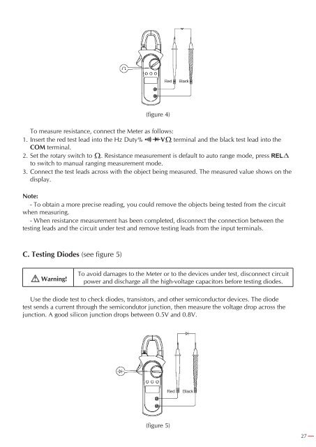
(figure 4)To measure resistance, connect the Meter as follows:1. Insert the red test lead into the Hz Duty% V terminal and the black test lead into theCOM terminal.2. Set the rotary switch to . Resistance measurement is default to auto range mode, press RELto switch to manual ranging measurement mode.3.. Connect the test leads across with the object being measured. The measured value shows on thedisplay.Note:- To obtain a more precise reading, you could remove the objects being tested from the circuitwhen measuring.- When resistance measurement has been completed, disconnect the connection between thetesting leads and the circuit under test and remove testing leads from the input terminals.C. Testing Diodes (see figure 5)Warning!To avoid damages to the Meter or to the devices under test, disconnect circuitpower and discharge all the high-voltage capacitors before testing diodes.Use the diode test to check diodes, transistors, and other semiconductor devices. The diodetest sends a current through the semicondutor junction, then measure the voltage drop across thejunction. A good silicon junction drops between 0.5V and 0.8V.(figure 5)27.