recuperadores de calor heat recovery units recuperateurs de ...
recuperadores de calor heat recovery units recuperateurs de ...
recuperadores de calor heat recovery units recuperateurs de ...
- No tags were found...

Create successful ePaper yourself
Turn your PDF publications into a flip-book with our unique Google optimized e-Paper software.
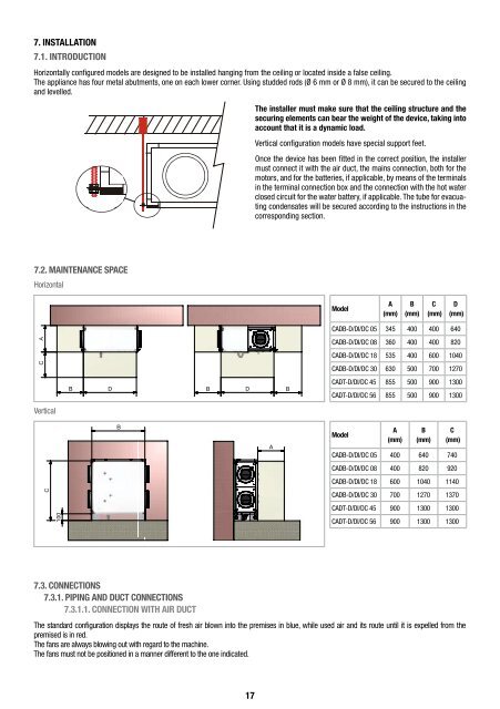
7. INSTALLATION7.1. INTRODUCTIONHorizontally configured mo<strong>de</strong>ls are <strong>de</strong>signed to be installed hanging from the ceiling or located insi<strong>de</strong> a false ceiling.The appliance has four metal abutments, one on each lower corner. Using stud<strong>de</strong>d rods (Ø 6 mm or Ø 8 mm), it can be secured to the ceilingand levelled.The installer must make sure that the ceiling structure and thesecuring elements can bear the weight of the <strong>de</strong>vice, taking intoaccount that it is a dynamic load.Vertical configuration mo<strong>de</strong>ls have special support feet.Once the <strong>de</strong>vice has been fitted in the correct position, the installermust connect it with the air duct, the mains connection, both for themotors, and for the batteries, if applicable, by means of the terminalsin the terminal connection box and the connection with the hot waterclosed circuit for the water battery, if applicable. The tube for evacuatingcon<strong>de</strong>nsates will be secured according to the instructions in thecorresponding section.7.2. MAINTENANCE SPACEHorizontalMo<strong>de</strong>lA(mm)B(mm)C(mm)D(mm)C AB D B D BD B B DVerticalCADB-D/DI/DC 05 345 400 400 640CADB-D/DI/DC 08 360 400 400 820CADB-D/DI/DC 18 535 400 600 1040CADB-D/DI/DC 30 630 500 700 1270CADT-D/DI/DC 45 855 500 900 1300BCADT-D/DI/DC 56 855 500 900 1300CC100100B BA AMo<strong>de</strong>lA(mm)B(mm)C(mm)CADB-D/DI/DC 05 400 640 740CADB-D/DI/DC 08 400 820 920CADB-D/DI/DC 18 600 1040 1140CADB-D/DI/DC 30 700 1270 1370CADT-D/DI/DC 45 900 1300 1300CADT-D/DI/DC 56 900 1300 13007.3. CONNECTIONS7.3.1. PIPING AND DUCT CONNECTIONS7.3.1.1. CONNECTION WITH AIR DUCTThe standard configuration displays the route of fresh air blown into the premises in blue, while used air and its route until it is expelled from thepremised is in red.The fans are always blowing out with regard to the machine.The fans must not be positioned in a manner different to the one indicated.17