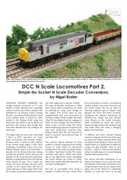
DCC N Scale Locomotives Part 1 - Bachmann
DCC N Scale Locomotives Part 1 - Bachmann
DCC N Scale Locomotives Part 1 - Bachmann
- TAGS
- locomotives
- bachmann

Create successful ePaper yourself
Turn your PDF publications into a flip-book with our unique Google optimized e-Paper software.
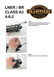
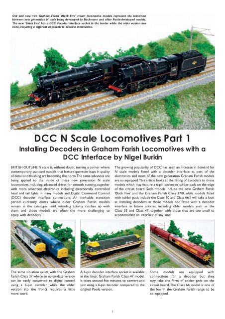
Carefully remove the analogue plug fromthe socket with tweezers.Four screws are released using a finejewellers cross-head screwdriver.The analogue plug is simple to remove.The motor is revealed in this picture.A piece of insulation tape should be appliedto it if the chosen decoder has no sleeve.Note the interface socket Pin No.1 (A);the dot identifying Pin No.1 on the decoder(B) and the corresponding numbers on theanalogue plug (C).The decoder simply plugs in like this.The motor and decoder interface socket areshown; it being the same arrangement as inthe Black 5 model.Many of the latest diesel locomotive modelsare fitted with decoder interface socketstoo, such as the brand new Class 37/0.Bodies are usually clipped in place andremoved by hand as demonstrated inthis picture.The new decoder is a straightforward fit.Job done! Should the decoder not have aninsulating sleeve, apply some insulatingtape to the metal chassis frame beforeplugging it in.In a few minutes, the Black 5 is readyfor testing.Sometimes, the coal load does notconveniently fall out of the tender.There are retaining screws holding thetender body to the chassis as seen on the'Royal Scot' model.With the body removed, this is thearrangement to be found. Note the circuitboard with digital interface socket andsprung connections for the locomotive'srunning lights.Here is a close up of the analogue plug (A)and socket with identifying numbers (B),together with room for a decoder arelocated at one end. Note that the pinnumbers are repeated on the circuitboard too (C).3Multiple unit models such as the Class 150also have sockets, one in both the poweredcar and the trailer car, so lighting circuitswill function.Installing decoders to solder padinterfaces:Upon removing the body from models likethe Graham Farish Class 60 and Class 66,you will notice that there is no 6 pin socketto hand. The models are equipped with a<strong>DCC</strong> interface, however, and space in thetop of the chassis for a decoder too.Each solder pad is numbered andcorresponds to a specific decoder wire.Clearly, the simple 'plug and play' 6 pinNEM651 cannot be installed unless a specialadapter harness is used. An alternative is toinstall a 'micro decoder', one similar to the6 pin type but with coloured harness wires.The wires are colour coded dependingupon their function.