DCC N Scale Locomotives Part2(671KB) - Bachmann
DCC N Scale Locomotives Part2(671KB) - Bachmann
DCC N Scale Locomotives Part2(671KB) - Bachmann
- No tags were found...

You also want an ePaper? Increase the reach of your titles
YUMPU automatically turns print PDFs into web optimized ePapers that Google loves.
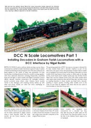
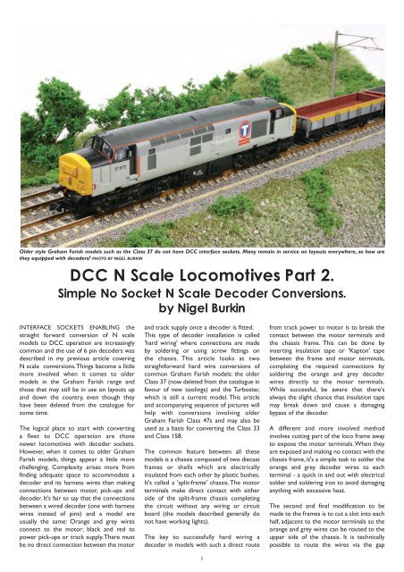
etween the frame halves but pinching thewires is most likely when the chassis isreassembled, exposing the cable and causinga damaging short.At the start, both models were checked tosee how well they ran and were checked forlubrication. Do not install a decoder in apoorly running model because it is unlikelyto improve matters! Next, look for space toaccommodate a 6 pin <strong>Bachmann</strong> decoderand adapter in the roof space of the model.Fortunately, many of the older GrahamFarish models have space in the roof areaand that can be made useful by carefullyshaving away part of the inner roof ribs;including both the Class 37 and Class 47, butnot the Turbostar. The Class 37 wasequipped with a 6 pin adapter as offered by<strong>Bachmann</strong>. Once completed, the wiring wastested using a 6 pin dummy plug on analoguecontrol. With testing complete, a <strong>Bachmann</strong>6 pin decoder was plugged in and theinstallation tested again, this time on aservice (programming) track.I chose a decoder with harness wires(Digitrax DZ125) for the Turbostar as spacewas too tight for other wiring options suchas an adapter and 6 pin decoder. Someplaying around soon determined that therewas enough space with air for the decoderto remain cool during operations at theinner end of the chassis. This was found byholding the body against the chassis as if itwere assembled and seeing where spacesexist. To help matters further, a little (not all)of the sheath on the decoder was paredaway with a sharp scalpel without exposingcomponents on the decoder.I used simple tools to complete theproject and I place emphasis on cleanlinessof the work area so filings and metal debrisis not left in the chassis where it coulddamage moving parts after the modelis reassembled.The chassis in both original Graham FarishClass 37 and 47 models is more or less thesame, requiring the same techniques to fita decoder.<strong>Bachmann</strong> offers both a 6 pin decodersuitable for N scale models and a 6 pininterface adapter socket and lead. Bothoffer the perfect solution for many olderGraham Farish models.Remove the fuel tank moulding beforeattempting to separate the chassis parts orit will get in the way!Unfortunately, the chassis blocks extendinto the tank area and cannot be used toaccommodate a decoder should that seemto be a good solution.Two screws hold the chassis frame together.Do not loose the plastic spacers thatkeep both sides electrically isolated fromeach other.Tools and materials:• Soldering iron.• Electrical solder (cored).• Insulation tape.• 3:1 heat shrink sleeve (optional).• <strong>Bachmann</strong> decoder adapter.• Xuron shears.• Jewellers screwdrivers• Fine cut needle file.• Modelling knife.• Cutting disc and mini drill.• Scrap of black 20thou styrene.• Digitrax DZ125 decoder for theTurbostar.• <strong>Bachmann</strong> 6 pin decoder for theClass 47The bodies of most Graham Farish diesellocos are lightly clipped in place and areeasily removed by simply pulling them awayfrom the chassis.A useful technique to judge how muchspace is available between body and chassisis to hold them together like this.The motor sits between the chassis shellswith a direct contact made between themotor and both sides of the chassis itself.Chassis components to note include themotor terminals (A) together with thechassis contact points (E); the motor casingdoes not require insulating (B); flywheelsshould be left as they are (C) and vitalinsulating bushes electrically separate thechassis frame into two halves (D).2
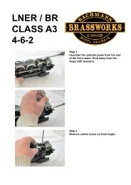
Key to fitting decoders is to isolate themotor from being directly supplied withtrack power. The contact point betweenmotor and chassis must be removed.The motor contact points on the die-castchassis frames are snipped away with Xuronshears and the hole opened up with a file.Trimming a small part of the interior ribs isall that is necessary for the harness wires tosit flat against the loco roof.A small spot applied to the harnessidentifies pin No.1.I chose not to do so, coiling the unusedwhite, blue and yellow function wires underinsulation tape to keep them out of harm'sway, just in case I wish to try a lightingproject on the model in the future.The decoder was fitted to the inner end ofthe chassis using a piece of 20 thou styrenecard to insulate it from the metal chassis, apoint which is most important to preventthe decoder from shorting on the metal.Some of the insulating sleeve was removedfrom the decoder to further reduceits size, although I did avoid exposing anycomponents. Take care when doing thistask with a modelling knife as decodercomponents are very delicate!The chassis was dismantled and the drivecomponents set aside in a safe place asbefore. The direct connection betweenmotor and chassis was broken by cuttingaway and filing back the contact points withcare taken to remove all filings beforereassembling the chassis. The followingsequence of pictures demonstrates how theconversion was undertaken. It took aroundtwo hours of patient work to complete to'service mode' testing stage.The motor is test fitted to the modifiedchassis to check that the connectionbetween the two no longer exists. Keepfiling metal away until there is definitely nocontact possible.When installing decoders, avoid pinching theharness or adapter wires between themotor and chassis frame. Adequate roomfor wires are cut into both parts of theframes with a cutting disc or file. Smallmodifications to the inside of the body areneeded to ensure there is room for decoderand harness.Connections are completed red and blackto each side of the split chassis frame;whilst the orange and grey wires aresoldered to the motor terminal. The model'sconnections can be tested using analogue6-pin plug before a decoder is fitted.Turbostar:Conversion of the Turbostar runs along thesame lines as the Class 37 and Class 47;the only difference being the available spacein the model and where it is located.This determines the choice of decoder and,whilst the same 6 pin adapter harnessand decoder would have been the preferredchoice, the lack of space for both demandeda different type of decoder: a wired version.In this case, I chose a Digitrax DZ125 whichhas wires soldered to its circuit board. In anyevent wires can be shortened to save spaceif desired and unwanted function wiresremoved completely by snipping them shortif space is truly tight in a particular model.The Turbostar body simply pulls off to revealits heavy metal split frame chassis.There is a useful set of contacts to which aTV suppression capacitor is soldered andthis will make the connection of the redand black decoder wires simple to do.The motor is hidden under insulation tape.3
Here's another body to chassis test fit tosee what space there may be for a decoderbetween chassis and roof. The chassisends also offer some opportunity toaccommodate a micro decoder.The motor is supplied with power througha direct contact between motor terminals(A) and chassis frame (B). This contact mustbe isolated on both sides of the motor.The chassis is reassembled and the decoderplaced at the inner end, on a pad of styrenecard to both insulate it from the chassis andto support it. It is glued in place with doublesided tape.It appears that a Digitrax DZ125 with partof its insulating sleeve cut away will fit at theend of the chassis. Ultimately, I turned it by90 degrees to avoid placing harness wiresunder too much stress.Once again, the safest, if not the simplestway to break the contacts is to simply cutaway a section of the chassis frame adjacentto the under terminals. My Xuron shearsmade short work of the relatively soft metal.The final connections: orange and grey wiresto the motor (wire them the right wayround so forward motion results whenthe controller is set to forward) (A); red andblack soldered to convenient tags onthe chassis frame (B); decoder safelyaccommodated at the end of the chassis (C)and unused function wires carefullystowed away in case they are needed in thefuture (D)!Separate the chassis frame by undoingthe two screws after removing theunderframe moulding.Clean up with a file to enlarge the openingto have the motor terminals safely isolatedfrom the chassis frames. Clean away filingsand metal fragments before putting thechassis back together.Some insulation tape tidies everything upneatly. Note that no tape is ever applied todecoders: they need some breathing spaceas part of their operation.The motor drive components and bogiemounts are enclosed between the chassisshells. Do not lose the insulation spacers!Points to note include:A: Bogie to chassis frame contacts.B: Drive shafts.C: Insulation bushes located betweenthe chassis frame.D: Flywheels.E: Worm gear located at top of thebogie gear tower.F: Motor casing.Once again, a slot is cut in the chassis frameto accommodate decoder wires without therisk of pinching. Wires can be reinforcedwith 3:1 heat shrink sleeve if rubbing of theinsulation is a possibility.All photography by Nigel Burkin4Although a relatively recent model, theClass 170 'Turbostar' has no <strong>DCC</strong> interfacesocket and a split-frame chassis. Convertingthe model is not as difficult as one mightimagine, the most challenging aspect isfinding suitable space to safelyaccommodate the decoder.