Dwyer Series Mark II Model 25 Molded Plastic ... - Solutions Direct
Dwyer Series Mark II Model 25 Molded Plastic ... - Solutions Direct
Dwyer Series Mark II Model 25 Molded Plastic ... - Solutions Direct

Create successful ePaper yourself
Turn your PDF publications into a flip-book with our unique Google optimized e-Paper software.
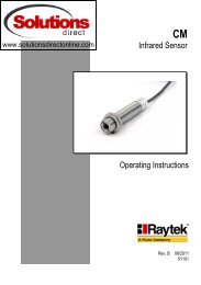
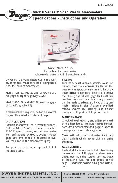
<strong>Mark</strong> <strong>II</strong> <strong>Series</strong> <strong>Molded</strong> <strong>Plastic</strong> ManometersBulletin D-58Specifications - Instructions and Operation<strong>Mark</strong> <strong>II</strong> <strong>Model</strong> No. <strong>25</strong>inclined-vertical manometer,(shown with optional A-612 portable stand)<strong>Dwyer</strong> <strong>Mark</strong> <strong>II</strong> Manometers come in a varietyof ranges. Make sure the oil being usedis for the correct manometer.<strong>Mark</strong> <strong>II</strong> #<strong>25</strong>, 27, MM-80 and M-700 Pa usered gage oil (specific gravity 0.826).<strong>Mark</strong> <strong>II</strong> #26, 28 and MM180 use blue gageoil (specific gravity 1.9).If additional oil is required, call or fax nearest<strong>Dwyer</strong> office listed at bottom of page.INSTALLATIONPosition manometer on a vertical surface.Drill two 1/8˝ or 9/64˝ holes on a vertical line315/16˝ apart. Loosely mount manometerwith self-tapping screws provided. Adjustgage until level bubble is centered in levelvial, then secure the manometer tightly.For portable use, order optional A-612Portable Stand.FILLINGTurn the zero set knob counterclockwise untilit stops, then turn clockwise 3 full turns. Thisputs zero in approximately the middle of thetravel adjustment in either direction. Removethe fill plug and fill with gage fluid until fluidreaches zero on scale. Minor adjustmentscan be made to adjust zero by adjusting zeroknob. Replace fill plug. If gage is overfilled,remove excess by inserting pipe cleanerthrough the fill port to blot up excess oil.MAINTENANCECheck oil level regularly and adjust zero withzero adjust knob. Be sure tubing connectionsare disconnected and gage is open toatmosphere before adjusting zero.Clean with mild soap and water. Avoid anycleaning fluids which may result in damagingthe gage.ACCESSORIESEach <strong>Mark</strong> <strong>II</strong> manometer includes two tubingconnectors for 1/8˝ pipe or sheet metalducts, two mounting screws, 3/4 oz. bottleof indicating fluid, red and green pointerflags, 8´ of double column tubing and instructions.DWYER INSTRUMENTS, INC. Phone: 219/879-8000 www.dwyer-inst.comP.O. BOX 373 • MICHIGAN CITY, INDIANA 46361, U.S.A. Fax: 219/872-9057 e-mail: info@dwyer-inst.com
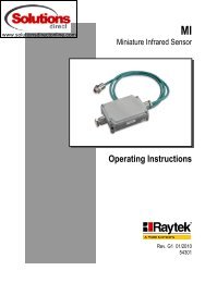
APPLICATIONSMARK <strong>II</strong> MANOMETERPITOT TUBE(SECTIONENLARGEDTO SHOWDETAIL)FLOWPtPsPITOT TUBE SENSES TOTAL AND STATIC PRESSURES. MANOMETERMEASURES VELOCITY PRESSURE-(DIFFERENCE BETWEEN TOTAL ANDSTATIC PRESSURES).AIR FILTER GAGEMount gage within 3 ft. of filter bank. Installtubing adapters on each side of filter. Runtubing from clean side of filter to positivepressure side of gage (left fitting). Rundownstream side to low pressure side ofgage (right fitting). Install green and redarrows adjacent to indicating tube to indicatefilter condition.AIR VELOCITY METERA pitot tube should be used for air velocityreadings. Install the pitot tube and gagecarefully to ensure accuracy. Select a locationfor the pitot tube with al least four diametersof smooth straight sections of ductboth upstream and downstream. Installpitot tube in the center of duct with tipdirected into air stream. Connect the rightangle (leg parallel to tip) to negative (right fitting)and straight pitot tube connection topositive (left connection) of gage. The velocityreading shown on the gage is the centeror maximum velocity. For average velocityacross the full area, multiply by a factor of0.9.No’s. 27 and 28 require pitot tube at additionalcost. See Bulletin F-41-F.The velocity indicated is for dry air at 70°F,29.9˝ barometric pressure and a resultingdensity of 0.075 lb/ft 3 . For variation fromthese standard conditions, corrections maybe based upon the following data.AIR VELOCITY CALCULATIONS:Air Velocity = 1096.2where Pv = velocity pressure in inches ofwaterD = Air density in lb/ft 3Air Density = 1.3<strong>25</strong> xPBTPvDwhere PB = Barometric Pressure in inchesof mercuryT = Absolute Temperature (indicatedtemperature °F plus 460)Flow in cu. ft. per min. = Duct area in squarefeet x air velocity in ft. per min.√
Bulletin D-58Uso, Instalacion y MantenimientoMANOMETROS DWYER MARK <strong>II</strong>RANGOS<strong>Model</strong>o Rango Fluido<strong>25</strong>26M-80M-180M-700 Pa27 *28 *0~3˝ C.A.0~7˝ C.A.0~80 mm C.A.0~180 mm C.A.10~0~700 Pascal0~7.000 pie./min.0~10.500 pie./min.0,826 rojo1,9 azul0,826 rojo1,9 azul0,826 rojo0,826 rojo1,9 azul* Los modelos 27 y 28 requieren tubo Pitot, concosto adicional.INSTALACIONInstale el <strong>Mark</strong> <strong>II</strong> en una superficie verticaladecuada. El ambiente debe estar libre devapores de sustancias cloradas, o solventestales como benceno, acetona, tetraclorurode carbono, etc. El instrumento soportapresiones internas de hasta 10 PSI, o 0,703bar, y temperaturas de hasta 140°F ó 60°C.NO EXCEDA ESTOS LÍMITES!Perfore dos orificios de 3,6 mm en línea vertical,separados por 100mm, e instale elinstrumento con los tornillos autorroscantesprovistos con él. Sin apretar demaslado,coloque el instrumento vertical con ayudadel nivel incluido en la parte inferior derechadel mismo. Verifique que ha quedado verticaly repita el proceso si es necesario. Parauso portable, use el soporte vertical tipo A-612.LLENADOGire en sentido antihorario la perilla deajuste de cero hasta que se detenga; gírelanuevamente pero en sentido horario unastres vueltas, de modo de dejar la posibilidadde ajuste en cualquier dirección. Retire eltapón de llenado y comience a llenar elmanómetro lentamente hasta ver el líquidoen las cercanías del cero de la escala.ATENCION: Use solamente aceite rojode peso específico 0,826 para los modelos<strong>25</strong>; 27; MM-80 y M-700Pa. Usesolamente aceite azul de peso específico1,9 para los modelos 26; 28 y MM-180.Adjuste exactamente el cero del instrumentogirando la perilla según corresponda, yreponga el tapón de llenado. Si el ajustepreciso es imposible por exceso de llenado,retire nuevamente el tapón y extraiga elexceso introduciendo un limpiador detubos, que absorba el exceso.Con el instrumento se suministra un tuboplástico flexible doble de 2,4 m juntamentecon adaptadores para conexión a 1/8˝ NPT.Conecte el tubo marcado con una línea rojaal la entrada de alta presión mas elevada asensar. Repita el procedimiento con el tuborestante en la entrada de baja presión(LOW, a la derecha), y a la presión más bajaa sensar.MANTENIMIENTOVerifique de tanto en tanto el nivel de aceite,y reajuste el cero del instrumento según seanecesario. Asegúrese de haber venteado elinstrumento desconectando los tubos deconexión a proceso (entradas HIGH y LOWen la parte superior del manómetro).Agregue aceite solo si es necesario, utilizandolos aceites DWYER azul o rojo según
APLICACIONESMARK <strong>II</strong> MANOMETERPITOT TUBE(SECTIONENLARGEDTO SHOWDETAIL)FLOWPtPsPITOT TUBE SENSES TOTAL AND STATIC PRESSURES. MANOMETERMEASURES VELOCITY PRESSURE-(DIFFERENCE BETWEEN TOTAL ANDSTATIC PRESSURES).corresponda. No utilice otros fluidos puespodrían dañar el material. Para limpieza usesolo jabón neutro y agua, evitando solventesque puedan dañar el instrumento(vea Instalación). Limpie la perilla con unpincel pequeño y suave.MEDICIÓN DE TIROInstale un tubo de hierro de 1/8˝ (3,2 mm) omayor desde el conducto a medir hasta unadistancia de 1,5 m del instrumento. Use únicamenteal conector derecho (LOW). Sedebe prever la limpieza periódica para evitaracumulación de suciedad.INDICADOR DE PRESIÓN ESTÁTICATenga en cuenta que las velocidades de airesuperiores a 100 fpm (5 m/seg.) son unafuente de posibles errores en la medición.Es conveniente usar sondas para presiónestática. De no ser disponibles, ingrese lasconexiones al conducto, en ángulo recto ala corriente de aire, y deles una terminaciónsuave en los extremos.INDICADOR DE OBSTRUCCIÓN DEFILTROSInstale el manómetro a distancia no mayorde 1 m del banco filtrante. Conecte el ladode descarga del filtro al conector LOW en laparte superior del instrumento y el otrotubo,al conector HIGH y a la presión positiva.Retire el papel protector de la flechasautoadhesivas (roja y verde)y adhiéralasadyacentes al tubo indicador para marcarlecturas de filtro limpio y sucio.MEDICION DE VELOCIDAD DE AIRE ENCONDUCTOSSe requiere un tubo Pitot para esta aplicación.Instálelo bien centrado dentro delconducto, en una zona donde sea recto ysin obstrucciones por lo menos en distanciasde 4 diámetros tanto corriente arribacomo abajo del punto de inserción.Asegúrese que la punta del tubo Pitot estábien dirigida hacia la corriente de aire.Conecte el tubo doble a los conectoresHIGH y LOW, de modo de conectar LOW alconector en ángulo recto del tubo Pitot, y elrestante a HIGH. La velocidad leída es lamáxima, correspondiente al centro del conducto.Para calcular la velocidad promediomultiplique por 0,9. Esta velocidad correspondea aire seco, a 21°C a una presiónde 760 mmHg y de una densidad de 0,075/cuft. Para otras condiciones se debenaplicar factores de corrección de acuerdo alo siguiente:CALCULO DE VELOCIDAD DE AIREVelocidad de Aire =1096,2 √ (Pv/D)Donde Pv es la presión por velocidad en ˝de C. Agua.D: densidad del aire en #/pie 3Densidad de aire = 1,3<strong>25</strong> X (Pb/T)Para PB: presión barométrica en ˝ deMercurio, y T = Temperatura absoluta(°F+460)Caudal en pie 3 /min. = Area del conducto(pie 2 ) X Veloc. de aire (pie/min.)©Copyright 2009 <strong>Dwyer</strong> Instruments, Inc. Printed in U.S.A. 7/09 FR# 67-440215-00 Rev. 12DWYER INSTRUMENTS, INC. Phone: 219/879-8000 www.dwyer-inst.comP.O. BOX 373 • MICHIGAN CITY, INDIANA 46361, U.S.A. Fax: 219/872-9057 e-mail: info@dwyer-inst.com