Raytek Raynger 3i Series Infrared Thermometers ... - Solutions Direct
Raytek Raynger 3i Series Infrared Thermometers ... - Solutions Direct
Raytek Raynger 3i Series Infrared Thermometers ... - Solutions Direct
- No tags were found...
You also want an ePaper? Increase the reach of your titles
YUMPU automatically turns print PDFs into web optimized ePapers that Google loves.
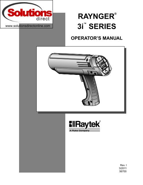
RAYNGER ®<strong>3i</strong> SERIESOPERATOR’S MANUALRUNLOGLOG RCL SET °C °FHI ( ) LO ( ) TambDCOUTSETRECALL•MODEACTIVATE•LOCKLASERRev. I3/201156700
WARRANTY<strong>Raytek</strong> warrants ea instrument it manufactures to be free from defects in material and workmanshipunder normal use and service for the period of one year from date of purase. Thiswarranty extends only to the original puraser. This warranty shall not apply to fuses, batteries,or any product whi has been subject to misuse, neglect, accident, or abnormal conditions ofoperation.In the event of failure of a product covered by this warranty, <strong>Raytek</strong> will repair the instrumentwhen it is returned to an authorized Service Facility within one year of the original purase,provided the warrantor’s examination discloses to its satisfaction that the product was defective.The warrantor may, at its option, replace the product in lieu of repair. With regard to any instrumentreturned within one year of the original purase, said repairs or replacement will be madewithout arge. If the failure has been caused by misuse, neglect, accident, or abnormal conditionsof operation, repairs will be billed at nominal cost. In su cases, an estimate will be submittedbefore work is started, if requested.THE FOREGOING WARRANTY IS IN LIEU OF ALL OTHER WARRANTIES, EXPREEDOR IMPLIED, INCLUDING BUT NOT LIMITED TO ANY IMPLIED WARRANTY OF MER-CHANTABILITY, FITNE, OR ADEQUACY FOR ANY PARTICULAR PURPOSE OR USE.RAYTEK SHALL NOT BE LIABLE FOR ANY SPECIAL, INCIDENTAL, OR CONSEQUEN-TIAL DAMAGES, WHETHER IN CONTRACT, TORT, OR OTHERWISE.WORLDWIDE HEADQUARTERS<strong>Raytek</strong> Corporation1201 Shaffer Road, PO Box 1820<strong>Raytek</strong> Santa Cruz, Corporation CA 95061-1820 USAWorldwide HeadquartersSantaPortableCruz,ProductsCA USADivisionTel:800 866 5478Phone 408+1 8314584581110– 3900solutions@raytek.comFax 408 425 4561WORLD WIDE WEBEuropean Headquarterswww.raytek.comBerlin, GermanyTel: +49 30 4 78 00 80raytek@raytek.deOffices worldwide:+1 800 227 – 8074 (USA and Canada only)EUROPEAN HEADQUARTERS<strong>Raytek</strong> GmbHArkonastrasse 45-49D-13189 Berlin, GermanyPhone 49 30 478 0080FAX 49 30 471 0251China BRAZIL HeadquartersBeijing, <strong>Raytek</strong> China do BrasilTel: Sorocaba, +86 Brasil 10 6438 4691info@raytek.com.cnPhone 55 152 276556CHINA<strong>Raytek</strong> China CompanyBeijing, ChinaPhone 86 10 437 0284MEXICO<strong>Raytek</strong> de MexicoPuebla, MexicoPhone 52 22 30 4380UNITED KINGDOM<strong>Raytek</strong> UKMilton Keynes, UKPhone 44 1 908 630800JAPAN<strong>Raytek</strong> Japan, Inc.Tokyo, JapanPhone 03 5976 1531® <strong>Raytek</strong> and <strong>Raynger</strong> are registered trademarks and <strong>3i</strong> is a trademark of <strong>Raytek</strong> Corporation© Copyright <strong>Raytek</strong> Corporation
TABLE OF CONTENTSSECTIONPAGE1.0 INTRODUCTION.............................................................................1-11.1 DESCRIPTION .......................................................................................................1-11.2 INVENTORY ..........................................................................................................1-21.3 MODEL IDENTIFICATION.................................................................................1-32.0 OPERATION ......................................................................................2-12.1 QUICK START........................................................................................................2-22.2 PRINCIPLES OF OPERATION............................................................................2-32.3 YOUR PORTABLE INFRARED THERMOMETER...........................................2-42.4 OPERATION AND CONTROLS.........................................................................2-62.4.1 Battery/AC Adaptor Installation....................................................................2-62.4.2 Control Panel and Display..............................................................................2-72.4.3 Control System ...............................................................................................2-102.4.3.1 Control Loops ..............................................................................................2-102.4.3.2 General Information....................................................................................2-112.4.4 RUN Loop—To Measure Temperature .......................................................2-122.4.5 LOG Loop—To Measure and Store Temperature......................................2-142.4.6 RECALL Loop—To Recall Measured Temperature ..................................2-162.4.6.1 RECALL Values from RUN .......................................................................2-162.4.6.2 RECALL Values from LOG........................................................................2-172.4.7 SETUP Loop—To Setup and Activate Alarms and Features ...................2-192.4.7.1 SETUP Values for RUN ..............................................................................2-192.4.7.2 SETUP Values for LOG...............................................................................2-212.5 USING A TRIPOD ...............................................................................................2-222.6 DATA OUTPUTS .................................................................................................2-232.6.1 Digital Output.................................................................................................2-242.6.1.1 Data Output—RUN Loop..........................................................................2-242.6.1.2 Data Output—SET Loop ............................................................................2-252.6.1.3 Data Output—LOG Run Loop ..................................................................2-262.6.1.4 Data Output—LOG SETUP Loop.............................................................2-272.6.2 Analog Output................................................................................................2-28<strong>Raynger</strong> <strong>3i</strong> <strong>Series</strong> Operator's ManualTable of Contents
SECTIONPAGE2.7 SIGHTING SYSTEMS..........................................................................................2-292.7.1 Single Laser Sighting .....................................................................................2-312.7.2 Dual Laser Sighting........................................................................................2-312.7.3 Crossed Laser Sighting..................................................................................2-322.7.4 Scope Sighting ................................................................................................2-323.0 SPECIFICATIONS ............................................................................3-13.1 THERMAL ..............................................................................................................3-13.2 OPERATIONAL .....................................................................................................3-23.3 ELECTRICAL .........................................................................................................3-33.4 ENVIRONMENTAL..............................................................................................3-43.5 PHYSICAL ..............................................................................................................3-43.6 DEFAULT VALUES ...............................................................................................3-53.7 REGULATORY .......................................................................................................3-64.0 MAINTENANCE...............................................................................4-14.1 BATTERY REPLACEMENT .................................................................................4-14.2 CLEANING ............................................................................................................4-14.2.1 Front Window Cleaning..................................................................................4-14.2.2 Cleaning the Housing......................................................................................4-24.3 LASER MAINTENANCE .....................................................................................4-2Table of Contents<strong>Raynger</strong> <strong>3i</strong> <strong>Series</strong> Operator's Manual
SECTIONPAGEAPPENDIX A: OPTICAL .............................................................................A-1HOW TO READ THE OPTICAL CHARTS...................................................................A-1OPTICAL CHARTS ..........................................................................................................A-2APPENDIX B: OBJECT EMIIVITY.......................................................... B-1HOW TO DETERMINE OBJECT EMIIVITY .............................................................B-1TYPICAL EMIIVITY VALUES.....................................................................................B-2APPENDIX C: TROUBLESHOOTING .......................................................C-1APPENDIX D: OPTIONS AND ACCEORIES.......................................D-1APPENDIX E: TRACEABILITY OFINSTRUMENT CALIBRATION..................................................................E-1GLOARY OF TERMSINDEX<strong>Raynger</strong> <strong>3i</strong> <strong>Series</strong> Operator's ManualTable of Contents
Table of Contents<strong>Raynger</strong> <strong>3i</strong> <strong>Series</strong> Operator's Manual
1.0 INTRODUCTION1.1 DESCRIPTIONThe <strong>Raynger</strong> ® <strong>3i</strong> series of instruments are portable infrared temperature measurementdevices. Each model is rugged and easy to use for making fast, noncontact, nondestructivetemperature measurements. They can measure operating temperatures ofmechanical, electrical, or production equipment without removing the equipmentfrom service. They can also measure product temperatures during manufacturing orstorage without contaminating or marring the product. Table 1-1 lists the standard<strong>Raynger</strong> <strong>3i</strong> models.Table 1-1: <strong>Raynger</strong> <strong>3i</strong> ModelsTEMPERATURE OPTICAL SPECTRALMODEL RANGE RESOLUTION RANGE SIGHTINGLTDL2 <DL3-30 to 1200°C(-20 to 2200°F)75:18-14 µdual laserLTSC-30 to 1200°C(-20 to 2200°F)75:18-14 µscopeLTCL2 <CL3-30 to 1200°C(-20 to 2200°F)75:18-14 µcrossed laserLRSC-30 to 1200°C(-20 to 2200°F)120:18-14 µscopeLRSCL2-30 to 1200°C(-20 to 2200°F)105:18-14 µsingle laser with scopeLRL2 &LRL3-30 to 1200°C(-20 to 2200°F)120:18-14 µsingle laserP7DL2 &P7DL310 to 800°C(50 to 1450°F)25:17.9 µdual laserG5SC150 to 1800°C(300 to 3275°F)50:15.0 µscope1MSC600 to 3000°C(1100 to 5400°F)180:11.0 µscope1ML2 &1ML3600 to 3000°C(1100 to 5400°F)180:11.0 µsingle laser2MSC200 to 1800°C(400 to 3275°F)90:11.6 µscope2ML2 &2ML3200 to 1800°C(400 to 3275°F)90:11.6 µsingle laser<strong>Raynger</strong> <strong>3i</strong> <strong>Series</strong> Operator’s Manual 1-1
Each model is molded from rugged, high-strength, solvent resistant plastic and isactuated by a two-stage trigger (second stage is used for data logging only). Eachmodel has the following:• High quality optical system• <strong>Infrared</strong> detector• Circuit board assembly with microprocessor• LCD display with backlighting feature• Touch-sensitive membrane switches for changing loops and modes• Battery compartment for four AA batteries• Power input jack for AC adaptor• Signal output jack (analog 1mV per degree/digital RS232)• A rugged, padded pouch for easy carryingThere are four types of laser sighting models:• Single laser—shows the center of the measurement area.• Dual laser—shows the spot diameter of the measurement area.• Crossed laser—the point where the two laser beams cross is the location of theminimum diameter measurement spot.• Single laser with scope1.2 INVENTORYYour <strong>Raynger</strong> <strong>3i</strong> package contains the following:• <strong>Raynger</strong> <strong>3i</strong>• Carrying Case• Operator’s Manual• Four (4) AA batteries• Warranty card1-2 <strong>Raynger</strong> <strong>3i</strong> <strong>Series</strong> Operator’s Manual
1.3 MODEL IDENTIFICATIONRefer to Table 1-1 for a list of standard models along with their temperature ranges,optical resolutions, spectral ranges, and sighting systems.You can determine the exact model number of your unit by looking at the manufacturinglabel on the underside of the unit. On the label is an area for model designation.The model type is printed in the following format:XXXYYYZZZZZwhere XXX is an abbreviation of the company name, YYY is the product (or abbreviationof the product name), and ZZZZZ is the model type. (Model type may be four orfive characters long. Refer to Table 1-1 to compare the label to model type.)<strong>Raynger</strong> <strong>3i</strong> <strong>Series</strong> Operator’s Manual 1-3
1-4 <strong>Raynger</strong> <strong>3i</strong> <strong>Series</strong> Operator’s Manual
2.0 OPERATIONThis portion of the manual contains the following sections:• Quick Start—To use your unit right away, follow the brief instructions on basicoperating procedures in this section.• Principles of Operation—A short introduction to infrared thermometry.• Your Portable <strong>Infrared</strong> Thermometer—Describes and illustrates the thermometer’scontrol panel, display, and features.• How to Operate—A detailed user guide that describes each of the operatingmodes. It includes descriptions of the RUN, RECALL, SETUP, and Data Loggerloops.• Data Outputs—How to use the analog and digital (RS232) outputs to connect thethermometer to a printer, chart recorder, or computer.WARNING—LASER SAFETYModels with laser sighting produce visible laser radiation that may beharmful to the human eye. Be aware of the following:• Avoid direct exposure of human eyes to laser light. Eye damagecan result.• Use extreme caution when operating.• Never point the unit at another person.• Keep out of the reach of children.• Refer to the FDA laser label on the unit for specific information.IMPORTANT1. If the unit is exposed to significant changes in ambient temperature(hot to cold or cold to hot), allow 45 minutes for temperature stabilizationbefore taking measurements.2. Do not operate the unit near large electrical or magnetic fields suchas arc welders and induction heaters. These fields can cause measurementerrors.3. For the short wavelength units (e.g., 2 µm and below)—Avoid takingtemperature measurements in bright sunlight. High levels of ambientlight may produce apparently valid high-temperature readingswhen no target is in the thermometer’s field-of-view.<strong>Raynger</strong> <strong>3i</strong> <strong>Series</strong> Operator’s Manual 2-1
2.1 QUICK STARTTo use your portable infrared thermometer right away, complete the following steps:Note:For complete definitions of your portable thermometer’s modes and functions, and for afull explanation on its operation, refer to Sections 2.3 and 2.4.1. Point the instrument at the object you want to measure (perpendicular to theobject) and pull the trigger. The current temperature (in °C or °F), the emissivityvalue, and the maximum measured temperature will be displayed (similar toFigure 2-1).2. Change the emissivity value to correspond to the material you are measuring bypressing the ▲ and ▼ buttons. (For example, if you are measuring wrought ironwith an 8-14 micron instrument, set emissivity to 0.90. If you are measuringasphalt, leave the emissivity at the default setting of 0.95. For other materials andfor instruments with other spectral ranges, refer to the emissivity charts inAppendix B.)°C or °F flashesRUNLOG RCL SET °C °FCurrent measuredtemperatureLOGSETHI ( ) LO ( ) T ambRECALL•MODELASERACTIVATE•LOCKUse the ▲ and ▼buttons to change theemissivity settingMaximum measuredtemperatureFigure 2-1: Quick Start Display2-2 <strong>Raynger</strong> <strong>3i</strong> <strong>Series</strong> Operator’s Manual
2.2 PRINCIPLES OF OPERATIONAn infrared thermometer and the human eye are very similar. An infrared thermometerhas a lens that focuses infrared radiation from an object onto a detector. Theeye focuses light onto the retina. The detector is stimulated by the incoming infraredenergy and produces a signal that is transmitted to the circuitry. The retina is stimulatedby incoming light and sends a signal to the brain. The circuitry processes thissignal and computes the temperature of the object.The intensity of an object’s emitted infrared energy increases or decreases in proportionto its temperature. The higher the temperature of the target, the greater the intensityof infrared radiation.To calibrate a noncontact temperature measurement instrument, the manufactureruses a blackbody. A blackbody is a perfect emitter because it absorbs and emits allradiant energy but reflects or transmits none. The emissivity value of a blackbody is1.00. Figure 2-2 shows the radiant emittance values of a blackbody at various temperaturesand wavelengths.Most objects have emissivities that are less than 1.00 but are reasonably uniform at allwavelengths of the infrared spectrum. These are called graybodies. The non-ideal(less then 1.00) emissivity values of different materials can be compensated for, by theemissivity controls, so that accurate temperature readings can be obtained. Emissivityvalues for many common materials (both metals and non-metals) are listed inAppendix B.10 2 1Blackbody Radiant Emittance (Watt/cm )2101101010-1-2-31500°C (2730°F)1000°C (1830°F)542°C (1000°F)260°C (490°F)20°C (70°F)-4100 1 2 3 4 5 6 7 8 9 10 11 12 13 14Wavelength (Microns)Figure 2-2: Blackbody Radiation Curves<strong>Raynger</strong> <strong>3i</strong> <strong>Series</strong> Operator’s Manual 2-3
2.3 YOUR PORTABLE INFRARED THERMOMETERPortable infrared thermometers measure surface temperatures without touching thesurface. They collect the infrared energy radiated by a target and compute its surfacetemperature. They also compute the running average, maximum, minimum, and differentialtemperatures and present them on a digital display in either degrees Celsiusor Fahrenheit. A digital/analog output allows data recording, instrumentation orprocess control, and/or remote display of temperature and emissivity. The instrumentis battery powered or can be powered by an optional AC adaptor.Internal memory circuits store temperature data for later recall, and a datalogging featureallows you to store up to 100 temperature, emissivity, and alarm readings (valuablefor comparative analysis).Figure 2-3 shows the features of the portable infrared thermometer.Sighting ScopeControl Paneland DisplayRUN▲▼LOGLOG RCL SET °C °FHI ( ) LO ( ) Tamb▲▼DCOUTSETRECALL•MODEACTIVATE•LOCKTrigger (2-stage)Digital/Analog OutputDC Inputfor AC AdaptorBattery AccessFigure 2-3: FeaturesTripod Mount Fitting2-4 <strong>Raynger</strong> <strong>3i</strong> <strong>Series</strong> Operator’s Manual
Your portable thermometer has the following:• Trigger—Two-stage trigger. The first stage activates the unit to take temperaturereadings. The second stage is functional only in the datalog mode. To store a temperaturereading, pull the trigger all the way in until you hear the tone (the tonesignals that the reading has been stored). When you release the trigger, the unitgoes to sleep.• Control Panel and Display—All controls (except the trigger) are located on thecontrol panel. The display shows temperature and setup values, mode and loopstatus, and operating information.• Sighting System—Laser or scope sighting is provided with each model.Note:Read the laser warning label before operating the laser.• Analog Output—Connects the instrument to analog recording/printing devicessuch as chart recorders and printers.• Digital Output—An RS232 interface to connect the instrument to a computer ordirectly to a printer’s RS232 port.• DC In—AC adaptor connection.<strong>Raynger</strong> <strong>3i</strong> <strong>Series</strong> Operator’s Manual 2-5
2.4 OPERATION AND CONTROLSThis section instructs you in the operation of the instrument. It describes batteryand/or AC adaptor installation and the controls and functions of the different controlloops and operating modes.2.4.1 Battery/AC Adaptor InstallationThe instrument may be powered by batteries or an AC adaptor. Battery power is suppliedby 4 “AA” batteries. The batteries are located in the base of the handle. ACpower is supplied by an optional AC power adaptor (DIN VDE 0551 approved).NiCad batteries can also be used, but battery life will be substantially reduced. Figure2-3 shows the location of the battery compartment, battery orientation, and the locationof the AC adaptor power connection.Table 2-1 shows approximate battery life (for alkaline batteries) for various operatingconditions.Table 2-1: Battery Life (Alkaline)CONDITIONLaser OFF Backlight OFFLaser ON Backlight OFFLaser OFF Backlight ONLaser ON Backlight ON"Sleep" mode (trigger off)HOURS OFCONTINUOUS USE2512.512.5101 yearNotes: Battery types and brands vary in length of usable life. The values in Table 2-1 areapproximate for new alkaline batteries. The instrument will continue to read accuratelyup to 4 hours after the low battery icon displays if the laser and backlight are off.Remove the batteries if the unit is not used for long periods of time.220 VAC adaptors must have DIN VDE 0551 approval to be used with IEC Class 2laser units.2-6 <strong>Raynger</strong> <strong>3i</strong> <strong>Series</strong> Operator’s Manual
2.4.2 Control Panel and DisplayFigure 2-4 shows the display and controls. Descriptions of these, in alphabeticalorder, follow the illustration.Backlight on/offbuttonRun/Logselector switchRUNLOG RCL SET °C °FIncrease/upbuttonLOGSetupbuttonSETHI ( ) LO ( ) T ambDecrease/downbuttonMode and RecallbuttonLaser on/off buttonRECALL MODE••RECALL MODELASERACTIVATE••LOCKActivate and triggerlock buttonData loggericonRecallloop iconSetuploop iconCelsius/FahrenheiticonsRUNLOGLOG RCL SET °C °FTemperaturedisplayHigh and lowalarm iconsTrigger lockiconHI ( ) LO ( ) T ambAmbient temperaturecompensation iconBacklighticonSETLow battery iconMode displayLaser on/off LEDRECALL MODE••RECALL MODELASERACTIVATE••LOCKEmissivity displayMode value displayFigure 2-4: The Control Panel and Display<strong>Raynger</strong> <strong>3i</strong> <strong>Series</strong> Operator’s Manual 2-7
Mode button—Press the mode button to change modes in any of the four loops.Mode display and Mode value display—The Mode display shows the current modeselected. The mode value display shows the temperature, set-point, or LOG locationvalue for the mode selected.Recall button and icon—Press the RCL button to activate the RECALL loop. TheRECALL loop may be used to recall values from either the RUN or LOG loops. TheRCL icon is activated when the instrument is in the RECALL loop.RUN button—Press the RUN/LOG button, when the trigger is pulled, to togglebetween the RUN and LOG loops.Setup button and icon—Press the SET button to activate the SETUP loop. TheSETUP loop may be used to set values in either the RUN or LOG loops. The SET iconis activated when the instrument is in the SET loop.T amb icon—This is activated when the ambient temperature compensation function isactivated. This feature only affects readings in the RUN loop; readings in the LOGloop are not affected.Trigger lock icon—The small padlock is the trigger lock icon and is activated whenLOCK is pressed while the trigger is pulled. To unlock the trigger, simply press theLOCK button again.<strong>Raynger</strong> <strong>3i</strong> <strong>Series</strong> Operator’s Manual 2-9
2.4.3 Control SystemThe control system consists of four loops: SET, RUN, RECALL and LOG. The instrumentmay be cycled to any of the four loops by using the trigger or control panel buttons,as shown below.SET LoopRUN LoopPull triggerRUNLOG RCL SET °C °FRUNLOG RCL SET °C °FLOGLOGSETHI ( ) LO ( )TambRelease trigger,press SETSETHI ( ) LO ( )Tamb• Trigger released• Press SET(SET icon actuated)RECALL MODEACTIVATE••••MODE LOCKRECALL LOCKLASERLASERRECALL MODEACTIVATE••••MODE LOCKRECALL LOCKLASERLASER• Pull or lock trigger• Press RUNRelease trigger,press SETPull trigger(previously in LOG)PressRUNLOGPull triggerRelease trigger,press RECALLRelease trigger,press RECALLRUNLOG RCL SET °C °FRUNLOG RCL SET °C °FLOGLOGSETHI ( ) LO ( )TambPull triggerSETHI ( ) LO ( )Tamb• Pull or lock trigger• Press LOG(LOG icon actuated)RECALL MODEACTIVATE••••MODE LOCKRECALL LOCKLASERLASERLOG Loop(previously in LOG)RECALL•MODEACTIVATE••LOCKLOCKLASERLASERRECALL Loop• Trigger released• Press RECALL(RCL icon activated)Figure 2-5: Control Loops2-10 <strong>Raynger</strong> <strong>3i</strong> <strong>Series</strong> Operator’s Manual
2.4.3.1 Control LoopsEach control loop has several modes, which are described in the following sections.2.4.3.2 General InformationBefore you begin using your portable instrument, you should be aware of the followinggeneral operating rules:• The instrument goes to “sleep” (low power consumption, no display, no laser, nobacklight) after different times for each loop, as follows:– SET Loop (after last button use): 10 seconds– RUN Loop (after releasing the trigger): immediately– RECALL Loop (after last button use): 10 seconds_LOG Loop (after releasing trigger): immediately• The backlight can be turned on or off in any mode.• The laser can be used only in the RUN and LOG loops.• The trigger has two stages. The first stage is for measuring temperature. The secondstage, when the trigger is pulled all the way in, is for storing temperature valuesin the LOG loop.• The °C or °F icon flashes when the instrument is measuring temperature in theRUN or LOG loops. It does not flash when values are recalled.• You can lock the trigger in the RUN loop and the LOG loop.• You must release the trigger to go into the SET or RECALL loops.• When you simultaneously press the MODE and ACTIVATE buttons while in theRUN loop, the instrument is reset to the RUN loop factory default settings (storeddata is unaffected). In the LOG loop, pressing the MODE and ACTIVATE buttonsnot only resets the instrument to its LOG loop factory default settings, but alsoclears all previously stored data. In both cases, the instrument will “beep” afterreinstalling the default settings. Section 3.6 lists default setting for each model aswell as non-model-specific default settings and range values.IMPORTANTFor the short wavelength units (e.g., 2 µm and below)—Avoid takingtemperature measurements in bright sunlight. High levels of ambientlight may produce apparently valid high-temperature readings whenno target is in the thermometer’s field-of-view.<strong>Raynger</strong> <strong>3i</strong> <strong>Series</strong> Operator’s Manual 2-11
2.4.4 RUN Loop–To Measure TemperatureThe RUN loop is for taking temperature measurements. Figure 2-6 illustrates theRUN loop.MAX ModeMIN ModeCurrenttemperatureRUNLOG RCL SET °C °FRUNLOG RCL SET °C °FLOGHI ( ) LO ( ) TambMODELOGHI ( ) LO ( ) TambSETSETRECALL MODEACTIVATE••••RECALLMODELOCKLOCKLASERLASERRECALL MODEACTIVATE••••RECALLMODELOCKLOCKTurn the triggerLASERlock ( ) on or offLASERwith the Lock buttonMODEThe °C (or °F) iconflashes when thetrigger is pulledMODERUNLOG RCL SET °C °FRUNLOG RCL SET °C °FLOGHI ( ) LO ( ) TambMODELOGHI ( ) LO ( ) TambSETSETRECALL MODEACTIVATE••••RECALLMODELOCKLOCKLASERLASERChange emissivitywith the ▲ and ▼buttons in any modeRECALL MODEACTIVATE••••RECALLMODELOCKLOCKLASERLASERAVG ModeDIF ModeTRIGGERPulled or LockedBUTTONRUNLOOP ICONNoneFigure 2-6: RUN LoopTo take a measurement, do the following:1. Point the instrument at the target.2. Pull the trigger (press the RUN/LOG button, if necessary, so that the LOG icon isnot activated).2-12 <strong>Raynger</strong> <strong>3i</strong> <strong>Series</strong> Operator’s Manual
3. Press the laser button to activate the laser (if equipped with laser sighting).4. Carefully aim using the laser or scope.Note:The laser or scope indicate the target (see Sections 2.7.1 through 2.7.4). Make sure thespot you are measuring fills the target.5. Read the temperature from the display.RUN contains 4 modes: MAX, MIN, DIF, and AVG (as shown in Figure 2-7). In RUN,the current temperature and emissivity setting along with either the MAX, MIN, DIF,or AVG temperature can be displayed. Note that AVG is a weighted average of allreadings taken since the trigger was pulled. The unit uses the following formula tocalculate the running average (while the trigger is pulled):R 1 + R 2 + R 3 + ...R nn= AVGwhere R = a reading and n = the total number of readings.• Press the MODE button to change modes.• Press the ▲ or ▼ buttons to change emissivity.• Press the backlight button if a brighter display is necessary.Note:When you simultaneously press the MODE and ACTIVATE buttons while in theRUN loop, the instrument is reset to its RUN loop factory default settings (stored datais unaffected). The instrument will “beep” after reinstalling the default settings.Section 3.6 lists default setting for each model as well as non-model-specific default settingsand range values.<strong>Raynger</strong> <strong>3i</strong> <strong>Series</strong> Operator’s Manual 2-13
2.4.5 LOG Loop–To Measure and Store TemperatureThe LOG loop is for making temperature measurements and storing them in the datalogger locations. Figure 2-7 illustrates the LOG loop.LOC ModeMAX ModeRUNLOG RCL SET °C °FRUNLOG RCL SET °C °FLOGHI ( ) LO ( )TambMODELOGHI ( ) LO ( )TambSETSETLock and unlockthe trigger withthe lock buttonRECALL MODE••MODE RECALLLASERLASERACTIVATE••LOCKUse the ▲ and ▼buttons to changethe log location (LOC)numberRECALL MODE••MODE RECALLLASERLASERACTIVATE••LOCKUse the ▲ and ▼buttons to changethe emissivityTRIGGERPulled or lockedBUTTONLOGLOOP ICONLOGTo use the modes and functions of the LOG loop, do the following:1. Point the instrument at the target.2. Pull the trigger and press the RUN/LOG button, if necessary, so that the LOG iconis activated.3. Press the ▲ or ▼ buttons to select the LOG location number where you want tostore the measurement. To change the emissivity setting for that location, pressthe MODE button and use the ▲ or ▼ buttons .4. Press the laser button to activate the laser (if equipped with laser sighting).5. Carefully aim using the laser or scope.6. Read the temperature from the display.Figure 2-7: LOG Loop2-14 <strong>Raynger</strong> <strong>3i</strong> <strong>Series</strong> Operator’s Manual
7. Pull the trigger further until you hear the “beep” indicating that the measurementhas been stored. Both the current and MAX temperatures are stored in memory.Notes: The instrument has a 2-stage trigger. The first stage is activated by pulling the triggera small amount. The second stage (operational in LOG only) is activated when thetrigger is pulled all the way.To protect the data from being accidentally overwritten (trigger accidently pulled),press the RUN/LOG button to exit the LOG loop (the LOG icon is off).8. Release the trigger.LOG contains two modes: LOC (location) and MAX (as shown in Figure 2-7). InLOG, the current temperature and emissivity setting along with either the locationnumber or MAX temperature can be displayed. Note the following:• Press the MODE button to change between LOC and MAX modes.• Press the ▲ or ▼ buttons to change the location number or the emissivity setting.• Press the backlight button if a brighter display is needed.Notes: If you change the emissivity after storing data, both the target temperature and MAXtemperature will reset to zero. The instrument will “beep” to indicate this.IMPORTANTWhen you simultaneously press the MODE and ACTIVATE buttonswhile in the LOG loop, all previously stored data is cleared. Theinstrument also resets to its LOG loop factory default settings. Theinstrument will “beep” after reinstalling the default settings. Section3.6 lists default setting for each model as well as non-model-specificdefault settings and range values.<strong>Raynger</strong> <strong>3i</strong> <strong>Series</strong> Operator’s Manual 2-15
2.4.6 RECALL Loop–To Recall Measured TemperaturesThe RECALL loop is for recalling values from either the RUN or LOG loops.2.4.6.1 RECALL Values from RUNFigure 2-8 illustrates RECALL for RUN values.MAX ModeMIN ModeLast temperatureRUNLOG RCL SET °C °FRUNLOG RCL SET °C °FLOGHI ( ) LO ( ) TambMODELOGHI ( ) LO ( ) TambSETSETRECALLACTIVATE•••MODELOCKLOCKLASERLASERUse the ▲ and ▼buttons to changethe emissivityRECALLACTIVATE•••MODELOCKLOCKLASERLASERMODEThe °C or °F iconis not flashingMODELast temperatureRUNLOG RCL SET °C °FRUNLOG RCL SET °C °FLOGHI ( ) LO ( ) TambMODELOGHI ( ) LO ( ) TambSETSETRECALL•MODEACTIVATE••LOCKLOCKLASERLASERAVG ModeIf the display goes out,press the Recall button againto continue the Recall functionRECALLACTIVATE•••MODELOCKLOCKLASERLASERDIF ModeTRIGGERReleased & UnlockedBUTTONRECALL & RUNLOOP ICONRCLFigure 2-8: RECALL Loop–Recalling RUN Values2-16 <strong>Raynger</strong> <strong>3i</strong> <strong>Series</strong> Operator’s Manual
To recall values from the RUN loop, do the following:1. Release or unlock the trigger, if necessary.2. Press the RECALL button. The RCL icon will be activated.3. Press the RUN/LOG button, if necessary, so that the LOG icon is not activated.4. Read the recalled temperature from the display.RECALL contains four modes: MAX, MIN, DIF, and AVG (as shown in Figure 2-8).In RECALL, the last temperature and emissivity setting along with either the MAX,MIN, DIF, or AVG temperature can be displayed. Note the following:• Press the MODE button to change modes.• Press the ▲ or ▼ button to change emissivity. (This shows the effect that a differentsetting would have. Note that if the target’s temperature is known, youcan determine its emissivity by this method. MAX, MIN, DIF, or AVG are notupdated.)• Press the backlight button if a brighter display is needed.2.4.6.2 RECALL Values from LOGFigure 2-9 illustrates RECALL for LOG values.LOC ModeMAX ModeRUNLOG RCL SET °C °FRUNLOG RCL SET °C °FLOGHI ( ) LO ( )TambMODELOGHI ( ) LO ( )TambSETPress the Recall buttonagain, if display goes out,to continue Recall functionRECALL MODE••MODE RECALLLASERLASERACTIVATE••LOCKStored temperature.If no temperatureis stored, the displayshows all zeros.Use the ▲ and ▼buttons to changethe log location (LOC)numberSETPress the Modebutton to togglebetween the LOCand MAX modes.RECALL MODEACTIVATE••••MODE RECALLLOCKLASERStored temperatures.LASERIf no temperaturesare stored, thedisplays showall zeros.TRIGGERReleased & UnlockedBUTTONRECALL & LOGLOOP ICONSLOGRCLFigure 2-9: RECALL Loop–Recalling LOG Values<strong>Raynger</strong> <strong>3i</strong> <strong>Series</strong> Operator’s Manual 2-17
To recall values from the LOG loop, do the following:1. Release or unlock the trigger, if necessary.2. Press the RECALL button. The RCL icon will be activated.3. Press the RUN/LOG button, if necessary, so that the LOG icon is activated.4. Read the recalled temperature from the display.5. Press the ▲ or ▼ buttons (LOC mode) to recall values from other LOG locations.RECALL contains two modes: LOC (location) and MAX (as shown in Figure 2-9). InRECALL, the stored temperature and emissivity setting along with either the locationnumber or MAX temperature can be displayed for each of the 100 LOG locations.2-18 <strong>Raynger</strong> <strong>3i</strong> <strong>Series</strong> Operator’s Manual
7. Set the TAM value by pressing the ▲ and ▼ buttons.8. Press the ACTIVATE button to turn on the ambient temperature compensationfunction. The Tamb icon will be displayed indicating that it is active. (PressingACTIVATE again turns off the function.)9. Pull trigger and reset the emissivity to the proper value for the target. You cannow take the target’s temperature using normal procedures. The current temperatureand all computed values, as well as the analog and digital outputs, will nowbe based on the compensated measurement.Note:TAM only affects readings in the RUN loop; LOG loop readings are not affected.2.4.7.2 SETUP Values for LOGFigure 2-11 illustrates SETUP for the LOG loop.LOC ModeHAL ModeRUNLOG RCL SET °C °FRUNLOG RCL SET °C °FLOGHI ( ) LO ( )TambMODELOGHI ( ) LO ( )TambSETSETPress the Set buttonagain, if the displaygoes out, to continuethe SETUP functionsRECALL MODE••MODE RECALLLASERLASERACTIVATE••LOCKPress the ▲ and ▼buttons to change theLog Location (LOC)number.You can select andlog data in any locationnumber from 1 to 100.Turn High Alarmon or off with theActivate buttonRECALL MODE••MODE RECALLLASERLASERACTIVATE••LOCKChange the High Alarmtemperature value withthe ▲ and ▼ buttonsTRIGGERReleased & UnlockedBUTTONSET & LOGLOOP ICONLOGSETFigure 2-11: SETUP Loop–LOG ValuesTo setup values for the LOG modes and functions, do the following:1. Release or unlock the trigger, if necessary.2. Press the SET button. The SET icon will be activated.3. Press the RUN/LOG button, if necessary, so that the LOG icon is activated.4. Press the ▲ or ▼ buttons to select the LOG location number (LOC mode).<strong>Raynger</strong> <strong>3i</strong> <strong>Series</strong> Operator’s Manual 2-21
5. Press the MODE button.6. Press the ▲ or ▼ buttons to change the HAL setting (HAL mode).7. Press ACTIVATE to activate the HAL setting for the selected location.SET contains two modes: LOC and HAL (as shown in Figure 2-11). In SET, the LOGlocation can be selected and the high alarm value (HAL) can be set for each location(independent of the setting for the RUN loop). Note the following:• Press the MODE button to change modes.• Press the backlight button if a brighter display is needed.2.5 USING A TRIPODThe instrument is equipped with a standard camera-type tripod mount fitting at thebase of the handle. You can set it up for continuous use by mounting it on a sturdytripod. This allows the instrument to be connected to a digital or analog recording orcontrolling device (computer, printer, chart recorder, line or temperature controller) tomonitor temperatures over long periods of time.Mounting the instrument is easy. Just attach it to the tripod by screwing the tripod’smounting screw into the fitting at the bottom of the handle.You can also connect a digital or analog recording or controlling device to the digital/analogconnector (labeled OUT) on the side of the instrument. For continuousmonitoring, pull the trigger and press the LOCK button.Note that battery life is shortened by continuous use. If you plan to monitor temperaturesover long intervals, you should connect an AC adaptor to the DC IN connector.2-22 <strong>Raynger</strong> <strong>3i</strong> <strong>Series</strong> Operator’s Manual
F0072 E095 MAX 0080F0072 E095 MAX 0080F0072 E095 MAX 0080F0072 E095 MAX 0080F0072 E095 MAX 0080F0072 E095 MAX 0080F0072 E095 MAX 0080F0072 E095 MAX 0080F0072 E095 MAX 0080F0072 E095 MAX 0080F0072 E095 MAX 0080F0072 E095 MAX 0080F0072 E095 MAX 0080F0072 E095 MAX 0080F0072 E095 MAX 00802.6 DATA OUTPUTSData outputs from the instrument provide a direct interface to chart recorders, printers,and computers. All models are equipped with an output jack capable of providinganalog and digital signals, which are user selectable in the SET loop. The formatof these signals are as follows:• Digital: RS-232Format: ASCII dataBaud Rate: 9600Data Format: 8 bits, 1 stop bit, no parity• Analog: 1 mV/° (°C or °F) for all models except the 1M1 mV/°C or 0.5 mV/°F for the 1MAnalogRS232RS232Figure 2-12: Data Outputs<strong>Raynger</strong> <strong>3i</strong> <strong>Series</strong> Operator’s Manual 2-23
2.6.1 Digital OutputThe following sections describe the digital data outputs for each mode.2.6.1.1 Data Output—RUN LoopIn the RUN loop, the temperature scale, current temperature, emissivity, mode temperature(MAX, MIN, DIF, or AVG), HAL or LAL, a carriage return, and a line feedare sent out at intervals determined by the DOI (set in the SET loop) when the triggeris pulled. HAL or LAL is sent out if the temperature is above HAL or below LAL(when they are activated). Three blank spaces replace HAL or LAL if they do notmeet this condition. There are 5 characters for the mode temperature. The fifth characteris always a space for MAX, MIN, or DIF. For AVG, the fifth character is a spaceif the average temperature is 1000° or above. Average temperatures up to 999.9° useall 5 characters. A total of 29 characters are sent out.Table 2-2 shows a sample output. The headings at the top of the table explain the contentsof each column (these are not part of the output).Table 2-2: RUN Mode Output ExampleS SSSSSppppppaaaaaa°C c Main c E for c Emissivity cc Mode c HAL, LAL, or Carriage Lineor °F e Temp e Emissivity e Value e Mode e Temperature e 3 Blank Spaces Return FeedF 0072 E 0 . 95 MAX 0072 F 0073 E 0 . 95 MAX 0073 F 0090 E 0 . 95 MAX 0090 F 0070 E 0 . 95 MAX 0090 F 0071 E 0 . 95 MAX 0090 HAL F 0081 E 0 . 95 MAX 0090 F 0080 E 0 . 95 MAX 0090 F 0070 E 0 . 95 MIN 0070 F 0070 E 0 . 95 DIF 0020 F 0081 E 0 . 95 AVG 088.4 F –018 E 0 . 95 AVG –11.5 F 0421 E 0 . 95 AVG 100.0 F 1480 E 0 . 95 AVG 999.9 F 1900 E 0 . 95 AVG 1000 F 0071 E 0 . 95 MAX 0090 F 0081 E 0 . 95 MIN –018 LAL F 0081 E 0 . 95 MIN –018 C 0027 E 0 . 95 MIN –028 C 0027 E 1 . 00 MIN –028 Notes(see below)12345678910112-24 <strong>Raynger</strong> <strong>3i</strong> <strong>Series</strong> Operator’s Manual
Notes:1. Indicates HAL is active and temperature HAL value.2. Mode changed to MIN.3. Mode changed to DIF.4. Mode changed to AVG.5. Main and Average temperatures went negative.6. Average temperature goes positive and is 100°F.7. Average temperature is up to 999.9°F.8. Average temperature is now greater than 999.9°F so decimal point is no longerdisplayed.9. Indicates LAL is active and temperature LAL value.10. Scale is changed from °F to °C.11. Emissivity is changed to 1.00.2.6.1.2 Data Output—SET LoopAfter entering the SET loop (SET icon activated), setup parameters can be sent out bypressing the SET button again. This information can be sent out at any time while stillin the SET loop. Unactivated setpoints are printed in lowercase (e.g., hal) and activatedsetpoints are printed in uppercase (e.g., HAL). Hi Alarm, Low Alarm, T. Ambient,Temperature Scale, and DOI are sent out and terminated by a carriage return and linefeed. A total of 39 characters are sent out. The SET values will be printed any timeyou press the SET button. Two examples follow:hal 0085 lal 0065 tam 0100 F;DOI 3600(hal, lal, tam not activated)HAL 0085 lal 0065 tam 0100 F;DOI 3600 (HAL activated)The above lines indicate Hi Alarm = 85, Low Alarm = 65, T. Ambient = 100, the temperaturescale is °F, and DOI = 3600 seconds. (The and do not print; thesedenote the carriage return and line feed.)Note:DOI does not apply to the SETUP mode.<strong>Raynger</strong> <strong>3i</strong> <strong>Series</strong> Operator’s Manual 2-25
2.6.1.3 Data Output—LOG Run LoopWhen you press the trigger (first stage only) in the LOG Loop, data will be sent outonly for those locations that have stored data. The temperature scale, stored maintemperature, stored emissivity, stored MAX temperature, location number, HAL, acarriage return, and a line feed are sent out when the trigger is pressed. HAL is sentout if the stored temperature is above or equal to the HAL value for that location, andHAL is activated. Three spaces replace HAL if this condition is not satisfied. A totalof 32 characters are sent out.Table 2-3 shows a sample output. The headings at the top of the table explain the contentsof each column (these are not part of the output).Table 2-3: LOG Run Mode Output ExampleS SSSSSSpppppppaaaaaaa°C c Main c E for c Emissivity c MAX c Stored MAX c Location c Carriage Lineor °F e Temp e Emissivity e Value e Mode e Temperature e Number e HAL Return FeedF 0072 E 0 . 95 MAX 0090 001 F 0095 E 1 . 00 MAX 0100 006 F 0070 E 0 . 95 MAX 0090 007 HAL F 0090 E 0 . 97 MAX 0100 100 Notes(see below)123Notes:1. Current and MAX temperature stored at Location 1.2. Current and MAX temperature stored, and the emissivity changed to 1.00 atLocation 6.3. Current and MAX temperature stored at Location 7, HAL is active, and thestored temperature is HAL value. When the 2-stage trigger is pulled all theway to store the current and maximum temperatures at Location 7, the currenttemperature also exceeded the HAL value, which was activated. Therefore,HAL was sent out at the end of the string.Notes: Note that in the above example nothing was stored at locations 2, 3, 4, 5, and 8 through99, so these locations were not sent out. There will be a pause in printing betweenlocations 1 and 6 and between locations 7 and 100 because the unit is searchingthrough the locations sequentially for stored data.DOI does not apply to the LOG mode.2-26 <strong>Raynger</strong> <strong>3i</strong> <strong>Series</strong> Operator’s Manual
2.6.1.4 Data Output—LOG SETUP LoopAfter entering the LOG SETUP loop (both the LOG and SET icons are activated),setup parameters are sent out when the SET button is pressed again. This informationcan be sent out at any time in the LOG SETUP mode. HAL, temperature scale,and the location number are sent out and terminated by a carriage return and linefeed. A total of 16 characters are sent out. Go to the appropriate location number inthe LOG loop and press the SET button to send out the Hi Alarm value for that location.Activated Hi Alarm locations are uppercase (HAL), and unactivated Hi Alarmlocations are lowercase (hal). Only the HAL value at the present location is sent out.For additional HAL values, go to the appropriate location and press SET again whilestill in any of the two screens in the LOG SETUP mode. To get the LOG SETUP parametersfor all 100 log locations, press the SET button for about 3 seconds.Table 2-4 shows a sample output. The headings at the top of the table explain the contentsof each column (these are not part of the output).Table 2-4: LOG SETUP Mode Output ExampleS S Spp paa ahal c HAL c °C c Location Carriage Lineor HAL e Value e or °F e Number Return Feedhal 1000 F 001 HAL 1000 F 002 hal 0085 F 003 hal 0085 F 004 hal 0085 F 005 hal 0085 F 006 hal 0085 F 007 HAL 0065 F 008 Notes(see below)12333334Notes:1. For Location 1, HAL is not activated and is 1000°F.2. For Location 2, HAL is activated and is 1000°F.3. For Locations 3, 4, 5, 6, and 7, HAL is not activated and is 85°F.4. For Location 8, HAL is activated and is 65°F.Note:DOI does not apply to the LOG SETUP mode.<strong>Raynger</strong> <strong>3i</strong> <strong>Series</strong> Operator’s Manual 2-27
2.6.2 Analog OutputThe analog output is made up of the following:• Output: 1 mV/° (°C or °F) for all models except 1M1 mV/°C or 0.5 mV/°F for the 1M• Output impedance: 1.3 KWUse the signal output jack accessory.The analog output represents the current temperature of the object being measured,regardless of the mode used. If Tamb compensation is activated, the analog outputwill be representative of the compensated temperature values.2-28 <strong>Raynger</strong> <strong>3i</strong> <strong>Series</strong> Operator’s Manual
2.7 SIGHTING SYSTEMSThe aiming options for this instrument are laser(s), scope, or laser and scope combination.Laser sighting is available in single or dual spot models or in a crossed laser model.Two different laser power levels are available for this product. Please refer to the label onyour unit and to the following label diagrams (Figure 2-13) to determine the one that youhave. The following table shows the specifications for both laser types.Table 2-5: Laser SpecificationsFDA Class IIIa FDA Class II and IEC Class 2TypeWavelengthPowerOperating Range(depending on ambientlight level)Gallium Arsenide630-670 nm
FDA Class IIAVOID EXPOSURE -LASER RADIATION ISEMITTED FROM THISAPERTURE.CAUTIONLASER RADIATION - DONOT STARE INTO BEAMOUTPUT < 1mWWAVELENGTH 630-670 nmCLASS II LASER PRODUCTCOMPLIES WITHFDA 21 CFRSUBCHAPTER JFDA Class IIIaPOR ESTA ABERTURASE EMITE RADIACIONLASER. EVITEEXPONER LA VISTA.AVOID EXPOSURE -LASER RADIATION ISEMITTED FROM THISAPERATURE.PELIGRORADIACION LASER – EVITEEXPONER LA VISTASALIDA < 5mWLONGITUD ` DE ONDA 630-670 nmPRODUCTO LASER CLASE IIIaDANGERLASER RADIATION - AVOIDDIRECT EYE EXPOSUREOUTPUT < 5mWWAVELENGTH 630-670 nmCLASS IIIa LASER PRODUCTCUMPLE CON LASNORMAS FDA 21 CFRSUB CAPITULO JCOMPLIES WITHFDA 21 CFRSUBCHAPTER JIEC Class 2y;y;y;y;y;y;y;y;y;y;y;y;y;y;y;y;y;y;y;y;y;y;y;y;y;y;y;y;y;y;y;y;y;y;y;y;y;y;y;y;y;y;y;y;y;y;y;y;y;y;y;y;y;y;y;y;y;y;y;y;y;y;y;y;y;y;y;y;y;y;y;y;y;y;y;y;y;y;y;y;y;y;y;y;y;y;y;y;y;y;y;y;y;y;y;y;y;y;y;y;y;y;y;y;y;y;y;y;y;y;y;y;y;y;y;y;y;y;y;y;y;y;y;y;y;y;y;y;y;y;y;y;y;y;
2.7.1 Single Laser SightingA single laser unit (see Figure 2-14) indicates the center of the area being measured,not the diameter of the spot. (To find out the diameter of the spot being measured,refer to the optical charts in Appendix A.)Figure 2-14: Single Laser Sighting2.7.2 Dual Laser SightingA dual laser unit indicates the diameter of the spot being measured. To take a measurement,aim the unit at the target and move closer or farther until the target is withinthe laser dots.Note:The IR and laser spot diameters are not the same at close distances. The distancebetween the laser beams is slightly greater than the spot being measured. Refer toFigure 2-15 for a comparison of the IR spot and laser beam diameters.Dual Laser Focus Point D:S = 75:1 @ 15 m (50 ft) Far Field D:S = 68:1SPOT DIA. (in)DISTANCE: SENSOR TO OBJECT (ft)010 20 30 40 501612840SPOT DIA. (mm)0 2751502253004 6 8 10 12 14 16DISTANCE: SENSOR TO OBJECT (m)IR Spot Diameter at Lens = 23 mm (0.9 in)Laser Diameter at Lens = 40 mm (1.6 in)IRLASERFigure 2-15: Dual Laser and IR Spot Diameters<strong>Raynger</strong> <strong>3i</strong> <strong>Series</strong> Operator’s Manual 2-31
2.7.3 Crossed Laser SightingThe distance at which the two laser dots overlap is the point where the smallest areais measured (Focus Point). To find this distance, aim the unit at the target and movecloser or farther until the laser beams overlap. Refer to Figure 2-16 for a comparisonof the IR spot and laser beam diameters.SPOT DIA. (in)Crossed Laser Focus Point D:S = 75:1 Far Field D:S = 20:1024 36 60 120 180Focus Point0.3 in @ 24 inDISTANCE: SENSOR TO OBJECT (in)129630SPOT DIA. (mm)Focus Point8 mm @ 610 mm0 6103001000 1500 3000 5000DISTANCE: SENSOR TO OBJECT (mm)75150225Figure 2-16: Crossed Laser and IR Spot Diameters2.7.4 Scope SightingScope sighting models (Figure 2-17) have parallax-free sighting (at the focus distance).Look through the scope. There are one or two circular reticles, depending on model.The inner reticle indicates the area that is measured at the focus point (see AppendixA for the focus point distance for your model). The outer reticle indicates an areagreater than or equal to the area that is measured at all other distances.Figure 2-17: Scope Sighting2-32 <strong>Raynger</strong> <strong>3i</strong> <strong>Series</strong> Operator’s Manual
2.7.5 Scope with Laser SightingThe scope and single laser sighting model (Figure 2-18) combines the parallax-free sightingof the scope with the convenience of the laser. The combination unit has a singleclass 2 laser. It indicates the center of the target being measured, not the diameter of thespot being measured. See section 2.7.1 and Figure 2-14 for further details on the laser.The scope has one reticle and it indicates the target area that is measured at the focuspoint (see Appendix A for the focus point distance of your model). See section 2.7.4 andFigure 2-17 for further details on the scope.Figure 2-18: Scope with Laser Sighting<strong>Raynger</strong> <strong>3i</strong> <strong>Series</strong> Operator’s Manual 2-33
2-34 <strong>Raynger</strong> <strong>3i</strong> <strong>Series</strong> Operator’s Manual
3.0 SPECIFICATIONSThis section covers the following specifications:• Thermal• Operational• Electrical• Environmental• PhysicalAlso covered are factory default settings for each model as well as factory default settingsand range values for all models.3.1 THERMALTable 3-1 lists thermal specifications for each model.Table 3-1: Thermal SpecificationsLT, LR, LRSCL2 1M 2M G5 P7MeasurementRange-30 to 1200°C(-20 to 2200°F)600 to 3000°C(1100 to 5400°F)200 to 1800°C(400 to 3275°F)150 to 1800°C(300 to 3275°F)10 to 800°C(50 to 1450°F)SpectralResponse8 to 14 micron1.0 micron1.6 micron5 micron7.9 micronDetectingElementThermopileSilicon diodeInGaAs diodeThermopileThermopileDisplayAccuracyAnalog OutputAccuracyRepeatabilityTemperatureCoefficient±1% of reading (±0.5% for 1M) or ±1°C (±1.5°F), whichever is greater, or ±2°C (±4°F)for targets below 0°C (32°F), at 23°C ±5°C (73°F ±9°F) ambient operating temp.±3mV of display reading±0.5% of reading or ±1°C (±1°F), whichever is greater±0.1°C (±0.1°F) change per 1°C (1°F) change in ambient temperature* The instrument may measure temperature a few degrees below the minimum andabove the maximum specified temperature range.Note:Hi Alarm, Lo Alarm, and T. Ambient ranges are the same as measurement ranges inTable 3-1.<strong>Raynger</strong> <strong>3i</strong> <strong>Series</strong> Operator’s Manual 3-1
3.2 OPERATIONALTable 3-2 lists operational specifications for each model.Table 3-2: Operational SpecificationsLT, LR, LRSCL2 1M 2M G5 P7TemperatureDisplayDisplay and DigitalOutput ResolutionDisplay ControlsEmissivityDOI (DigitalOutput Interval)Analog OutputResolutionLOG LocationsResponse Time(95% response)°C or °F (selectable), multifunctional 4-digit backlit LCD1°C or 1°F (0.1°C or 0.1°F in AVG Mode for temperatures up to 999.9°)Membrane Switch PanelAdjustable from 0.10 to 1.00 in 0.01 increments (default = 0.95)1 to 9999 seconds1°C or 1°F1 to 100700 msec 550 msec 550 msec 700 msec 700 msec3-2 <strong>Raynger</strong> <strong>3i</strong> <strong>Series</strong> Operator’s Manual
3.3 ELECTRICALTable 3-3 lists electrical specifications for each model.Table 3-3: Electrical SpecificationsLT, LR, LRSCL2 1M 2M G5 P7Analog Output1mV/°C (1mV/°F)1mV/°C (0.5mV/°F)1mV/°C (1mV/°F)Analog OutputRangeAnalog OutputImpedanceDigital OutputDigital OutputRangePowerRequirementsSame as Measurement Range in Table 3-11.3 KΩRS232, 9600 baudSame as Measurement Range in Table 3-1Four (4) AA alkaline or rechargeable batteries or 6 to 9 volt, 200 mA, DC power supply<strong>Raynger</strong> <strong>3i</strong> <strong>Series</strong> Operator’s Manual 3-3
3.4 ENVIRONMENTALTable 3-4 lists environmental specifications for each model.Table 3-4: Environmental SpecificationsLT, LR, LRSCL2 1M 2M G5 P7RelativeHumidityStorageTemperatureAmbientOperatingTemperature10 to 95% at up to 30°C (86°F)under non-condensing conditions-20 to 50°C (-4 to 120°F)without battery0 to 50°C (32 to 120°F)Note:The laser will turn off automatically if the instrument’s internal temperature exceeds45° C (113° F).3.5 PHYSICALTable 3-5 lists environmental specifications for each model.Table 3-5: Physical SpecificationsLASER MODELSSCOPE MODELSSCOPE & LASERDimensions208 mm (8.2 in) H257 mm (10.1 in) L71 mm (2.8 in) W244 mm (9.6 in) H257 mm (10.1 in) L71 mm (2.8 in) W244 mm (9.6 in) H257 mm (10.1 in) L71 mm (2.8 in) WWeight794 g (1.75 lbs) 1000 g (2.21 lbs)1000 g (2.21 lbs)3-4 <strong>Raynger</strong> <strong>3i</strong> <strong>Series</strong> Operator’s Manual
3.6 DEFAULT VALUESTable 3-6 lists the factory default values for each model.Table 3-6: Model Specific Factory Default ValuesHi Alarm Lo Alarm T. AmbientLTDL, LTCL, LTSC,LRSC, LRL, LRSCL21200°C(2200°F)0°C(0°F)23°C(73°F)1MSC, 1ML3000°C(5400°F)600°C(1100°F)600°C(1100°F)P7DL800°C(1450°F)10°C(50°F)23°C(73°F)G5SC1800°C(3275°F)150°C(300°F)150°C(300°F)2MSC, 2ML1800°C(3275°F)200°C(400°F)200°C(400°F)Table 3-7 lists factory default settings that are valid for all models.Table 3-7: Non-Model Specific Factory Default ValuesFunctionEmissivityDOI (Digital Output Interval)Digital/Analog OutputTrigger LOCKLaserBacklightHALLALTAMScale: U.S.Scale: Outside U.S.LoopSetup Screen (RUN Loop)Setup Screen (LOG Loop)LOG LocationLOG Data–All LocationsCurrent TemperatureMAX TemperatureHi Alarm ValueHi Alarm StateEmissivityDefault0.9560 secondsAnalog Outputoffoffoffoffoffoffdegrees Fdegrees CRUN Loop, MAX ModeF/CLOC (Location)10 degrees C, or 0 degrees F0 degrees C, or 0 degrees FSee Table 3-6off0.95<strong>Raynger</strong> <strong>3i</strong> <strong>Series</strong> Operator’s Manual 3-5
Note:When you simultaneously press the MODE and ACTIVATE buttons while in theRUN loop, the instrument is reset to its RUN loop factory default settings (stored datais unaffected). In the LOG loop, pressing the MODE and ACTIVATE buttons not onlyresets the instrument to its LOG loop factory default settings, but also clears all previouslystored data. In both cases, the instrument will “beep” after reinstalling thedefault settings. Section 3.6 lists default setting for each model as well as non-modelspecificdefault settings and range values.3.7 REGULATORYThe appropriate regulatory approvals and certificates have been issued as follows:• FDA Class II Laser Certification• FDA Class IIIa Laser Certification• IEC Class 2 Laser Certification• IEC801-3 (EN50082) for EMI susceptibility3-6 <strong>Raynger</strong> <strong>3i</strong> <strong>Series</strong> Operator’s Manual
4.0 MAINTENANCE4.1 BATTERY REPLACEMENTWhen the battery icon comes on, you need to replace the batteries. To open thebattery compartment, press gently on the middle of the sliding panel (located on thebottom of the handle) and slide it to the rear of the unit. Remove the batteries andreplace with four AA batteries. Be sure to insert the new batteries so they point in theproper direction. (A symbol on the side of the handle shows the proper battery orientation.)Replace the battery compartment cover.4.2 CLEANINGYou should periodically clean the instrument’s front window and housing.4.2.1 Front Window CleaningA dirty front window can cause temperature measurement errors. The window isfragile, and care should be taken when cleaning it to prevent scratching. Use cameralens or eye glass tissues to clean the window.Periodic cleaning can be done by completing one or more of the following:• Blow loose particles off the front window with clean air.Note:Unfiltered compressed air, as well as your own breath, can cause condensation onthe front window, which can trap dust particles instead of removing them.• Gently brush off particles with a soft camel-hair brush.• Thicker contaminants can be cleaned with water and a camera lens tissue.• For finger prints or grease, use either isopropyl alcohol, Ethanol, Xylene,Acetone, or Kodak ® Lens Cleaner. Apply to the front window, and wipe gentlywith a camera lens tissue until you see colors on the surface, then allow toair dry. Do not wipe the surface dry, as this may scratch the surface.CAUTIONDo not use any ammonia, or cleaners with ammonia, bleach, acids, orstrong bases. This can cause severe damage to the front window.<strong>Raynger</strong> <strong>3i</strong> <strong>Series</strong> Operator’s Manual 4-1
4.2.2 Cleaning the HousingTo clean the instrument’s housing, simply use soap and water or a mild commercialcleaner. Wipe with a damp sponge or soft rag. Use a soft rag to gently wipe the display.4.3 LASER MAINTENANCEIf the laser (laser models only) does not operate properly, call your infrared thermometersupplier. DO NOT open the instrument’s main housing.4-2 <strong>Raynger</strong> <strong>3i</strong> <strong>Series</strong> Operator’s Manual
APPENDIX A:OPTICALHOW TO READ THE OPTICAL CHARTSThe optical charts indicate the nominal target spot diameter at various distances fromthe sensing head. Information on the top line of each chart shows the different spotdiameters at the distances from the sensor given on the bottom line (see Figure A-1).All measurements are in millimeters or meters and inches.Target spot sizeat focus pointModelTypeLTCL2LTCL3Spot Diameter (in)Spot Diameter (mm)Distance from sensorto object in inches or feet036 60 120 180Focus Point0.3 in @ 24 in00.91000DISTANCE: SENSOR TO OBJECT IN INCHES238 mm @ 610 mm1.94815004.611830007.32035000DISTANCE: SENSOR TO OBJECT IN MILLIMETERSFOCUS POINT D:S = 75:1 FAR FIELD D:S = 20:1Diameter of targetspot size in inchesDiameter of targetspot size in millimetersDistance from sensor toobject in millimeters or metersIR Spot Diameter at Lens = 23 mm (0.9 in)Laser Diameter at Lens = 40 mm (1.6 in)IR Beam ProfileLaser ProfileFocus Point D:S = Distance to spot divided by spot diameter at the focus pointFar Field D:S = Ratio at distances greater than 10x the focus distanceHow to calculate spot sizesTo calculate a spot size between twoknown points on an optical chart, usethe following formula:(DS x = S n + x - D n )(Dx (S f - S n )f - D n )S x = Unknown spot sizeS n = Smaller known spot sizeS f = Larger known spot sizeD x = Distance to unknown spotD n = Distance to smaller known spotD f = Distance to larger known spotFigure A-1: How to Read the Optical Charts<strong>Raynger</strong> <strong>3i</strong> <strong>Series</strong> Operator’s Manual A-1
OPTICAL CHARTSNote that the optical resolution values are stated at minimum 90% energy (95% for 1M).Figure A-2: Optical ChartsLTCL2LTCL3Spot Diameter (in)DISTANCE: SENSOR TO OBJECT IN INCHES0 36 60 120 180Focus Point7.30.3 IN @ 24 IN4.61.90.9LTDL2LTDL3Spot Diameter (in)05 10 20 30 401.3 2.0DISTANCE: SENSOR TO OBJECT IN FEET3.55.06.5508.0Spot Diameter (mm)0238 mm @ 610 mm10004815001183000DISTANCE: SENSOR TO OBJECT IN MILLIMETERSFOCUS POINT D:S = 75:1 FAR FIELD D:S = 20:1IR Spot Diameter at Lens = 23 mm (0.9 in)Laser Diameter at Lens = 40 mm (1.6 in)IR Beam ProfileLaser Profile2035000Spot Diameter (mm)03351861241651.5 3 6 9 12DISTANCE: SENSOR TO OBJECT IN METERS203FOCUS POINT D:S = 75:1 @15 m (50 ft) FAR FIELD D:S = 68:115IR Spot Diameter at Lens = 23 mm (0.9 in)Laser Diameter at Lens = 40 mm (1.6 in)IR Beam ProfileLaser ProfileG5SCSpot Diameter (in)0DISTANCE: SENSOR TO OBJECT IN INCHES36 60 120 1801.0 1.3Focus Point1.5 IN @ 75 IN2.94.91ML21ML31MSCSpot Diameter (in)05 10 20 30 40Focus Point1.0 IN @ 15 FT0.5DISTANCE: SENSOR TO OBJECT IN FEET0.81.52.33.2504.0Spot Diameter (mm)27 327413738 mm @ 1900 mm0 1000 150030005000DISTANCE: SENSOR TO OBJECT IN MILLIMETERSFOCUS POINT D:S = 50:1 FAR FIELD D:S = 30:1IR Spot Diameter at Lens = 23 mm (0.9 in)Spot Diameter (mm)013183625 mm @ 4.6 m1.5 3 6 9 12DISTANCE: SENSOR TO OBJECT IN METERS578010015FOCUS POINT D:S = 180:1 FAR FIELD D:S = 140:1IR Spot Diameter at Lens = 7 mm (0.3 in)A-2 <strong>Raynger</strong> <strong>3i</strong> <strong>Series</strong> Operator’s Manual
DISTANCE: SENSOR TO OBJECT IN FEETLRSCL2Spot Diameter (in)010 20 30 404.83.81.92.8505.7LTSCSpot Diameter (in)0DISTANCE: SENSOR TO OBJECT IN INCHES36 60 120 1800.8 0.9Focus Point1.0 IN @ 75 IN2.13.6Spot Diameter (mm)477195119 1430 3 6 9 12 15DISTANCE: SENSOR TO OBJECT IN METERSFOCUS POINT D:S = 105:1 @ 15 m (50 ft) FAR FIELD D:S = 90:1IR Spot Diameter at Lens = 23 mm (0.9 in)Spot Diameter (mm)20 23539725 mm @ 1900 mm0 1000 150030005000DISTANCE: SENSOR TO OBJECT IN MILLIMETERSFOCUS POINT D:S = 75:1 FAR FIELD D:S = 40:1IR Spot Diameter at Lens = 23 mm (0.9 in)LRL2LRL3LRSCSpot Diameter (in)0DISTANCE: SENSOR TO OBJECT IN FEET10 20 30 404.13.31.72.4505.0Spot Diameter (mm)04361811023 6 9 12DISTANCE: SENSOR TO OBJECT IN METERS12415Spot Diameter (in)DISTANCE: SENSOR TO OBJECT IN FEET0 10 20 30 402ML2Focus Point6.82ML32.0 IN @ 15 FT4.92MSC 3.01.5508.8FOCUS POINT D:S = 120:1 @ 15 m (50 ft) FAR FIELD D:S = 100:1IR Spot Diameter at Lens = 23 mm (0.9 in)Spot Diameter (mm)0387412251 mm @ 4.6 m1712183 6 9 12 15DISTANCE: SENSOR TO OBJECT IN METERSFOCUS POINT D:S = 90:1 FAR FIELD D:S = 60:1IR Spot Diameter at Lens = 23 mm (0.9 in)P7DL2P7DL3Spot Diameter (in)Spot Diameter (mm)05 10 15 20 30 402.871DISTANCE: SENSOR TO OBJECT IN FEET5.17.510.014.512736320824819.54830 1.5 3 5 6 9 12DISTANCE: SENSOR TO OBJECT IN METERS5024.060315FOCUS POINT D:S = 25:1 @15 m (50 ft) FAR FIELD D:S = 23:1IR Spot Diameter at Lens = 23 mm (0.9 in)Laser Diameter at Lens = 40 mm (1.6 in)IR Beam ProfileLaser Profile<strong>Raynger</strong> <strong>3i</strong> <strong>Series</strong> Operator’s Manual A-3
A-4 <strong>Raynger</strong> <strong>3i</strong> <strong>Series</strong> Operator’s Manual
APPENDIX B: OBJECT EMISSIVITYHOW TO DETERMINE OBJECT EMISSIVITYEmissivity is a measure of an object’s ability to absorb, transmit, and emit infraredenergy. It can have a value from 0.0 (perfect mirror) to 1.0 (blackbody). When settingthe emissivity value on your sensor, if you set a higher than actual emissivity value,the output will read low (provided the target temperature is above the local’s ambienttemperature). For example, if you set 0.95 and the actual target emissivity is 0.9, thesensor’s reading will be lower than the target’s true temperature (when the targettemperature is above ambient).To determine an object’s emissivity, you can use any one of the following methods:1. Determine the actual temperature of the object using a sensor such as a ResistanceTemperature Device (RTD), thermocouple, or another suitable method. Next, useyour portable sensor to measure the object temperature and adjust the emissivitysetting until it shows the actual temperature. This is the correct emissivity for themeasured material.2. For objects with relatively low temperatures, up to 260°C ( 500°F), place a piece oftape, such as masking, on the object. Make sure the tape is large enough for themeasurementspot diameter. You do not want the spot to go beyond the tape’sedges. Next, measure the tape temperature using an emissivity setting of 0.95.Finally, measure an adjacent area on the object and adjust the emissivity settinguntil you reach the same temperature. This is the correct emissivity for the measuredmaterial.3. If a portion of the surface of the object can be coated, use a flat black paint. Next,measure the painted area using an emissivity setting of 0.93. Finally, measure anadjacent area on the object and adjust the emissivity setting until you reach thesame temperature. This is the correct emissivity for the measured material.<strong>Raynger</strong> <strong>3i</strong> <strong>Series</strong> Operator’s Manual B-1
TYPICAL EMISSIVITY VALUESThe following tables provide references for estimating emissivity and can be usedwhen none of the previous three determining steps are practical. Emissivity valuesshown in the tables are only approximate. Any or all of the following parameters canaffect the emissivity of an object:1. Temperature2. Angle of measurement3. Geometry (plane, concave, convex, etc.)4. Thickness5. Surface quality (polished, rough, oxidized, sandblasted)6. Spectral region of measurement7. Transmissivity (i.e., thin film plastics)Table B-1: Emissivity Values for MetalsMaterialEmissivity1.0µm 1.6µm 8-14µmAluminumUnoxidized 0.1-0.2 0.02-0.2 n.r.Oxidized 0.4 0.4 0.2-0.4Alloy A3003,Oxidized n.r. 0.4 0.3Roughened 0.2-0.8 0.2-0.6 0.1-0.3Polished 0.1-0.2 0.02-0.1 n.r.BrassPolished 0.8-0.95 0.01-0.05 n.r.Burnished n.r. n.r. 0.3Oxidized 0.6 0.6 0.5Chromium 0.4 0.4 n.r.CopperPolished n.r. 0.03 n.r.Roughened n.r. 0.05-0.2 n.r.Oxidized 0.2-0.8 0.2-0.9 0.4-0.8Electrical Terminal Blocks n.r. n.r. 0.6Gold 0.3 0.01-0.1 n.r.HaynesAlloy 0.5-0.9 0.6-0.9 0.3-0.8InconelOxidized 0.4-0.9 0.6-0.9 0.7-0.95Sandblasted 0.3-0.4 0.3-0.6 0.3-0.6Electropolished 0.2-0.5 0.25 0.15n.r. = not recommendedContinued on next pageB-2 <strong>Raynger</strong> <strong>3i</strong> <strong>Series</strong> Operator’s Manual
Table B-1 (continued): Emissivity Values for MetalsMaterialEmissivity1.0µm 1.6µm 8-14µmIronOxidized 0.4-0.8 0.5-0.9 0.5-0.9Unoxidized 0.35 0.1-0.3 n.r.Rusted n.r. 0.6-0.9 0.5-0.7Molten 0.35 0.4-0.6 n.r.Iron, CastOxidized 0.7-0.9 0.7-0.9 0.6-0.95Unoxidized 0.35 0.3 0.2Molten 0.35 0.3-0.4 0.2-0.3Iron, WroughtDull 0.9 0.9 0.9LeadPolished 0.35 0.05-0.2 n.r.Rough 0.65 0.6 0.4Oxidized n.r. 0.3-0.7 0.2-0.6Magnesium 0.3-0.8 0.05-0.3 n.r.Mercury n.r. 0.05-0.15 n.r.MolybdenumOxidized 0.5-0.9 0.4-0.9 0.2-0.6Unoxidized 0.25-0.35 0.1-0.35 0.1Monel (Ni-Cu) 0.3 0.2-0.6 0.1-0.14NickelOxidized 0.8-0.9 0.4-0.7 0.2-0.5Electrolytic 0.2-0.4 0.1-0.3 n.r.PlatinumBlack n.r. 0.95 0.9Silver n.r. 0.02 n.r.SteelCold-Rolled 0.8-0.9 0.8-0.9 0.7-0.9Ground Sheet n.r. n.r. 0.4-0.6Polished Sheet 0.35 0.25 0.1Molten 0.35 0.25-0.4 n.r.Oxidized 0.8-0.9 0.8-0.9 0.7-0.9Stainless 0.35 0.2-0.9 0.1-0.8Tin (Unoxidized) 0.25 0.1-0.3 n.r.TitaniumPolished 0.5-0.75 0.3-0.5 n.r.Oxidized n.r. 0.6-0.8 0.5-0.6Tungsten n.r. 0.1-0.6 n.r.Polished 0.35-0.4 0.1-0.3 n.r.ZincOxidized 0.6 0.15 0.1Polished 0.5 0.05 n.r.MaterialEmissivityn.r. = not recommended<strong>Raynger</strong> <strong>3i</strong> <strong>Series</strong> Operator’s Manual B-3
Table B-2: Emissivity Values for Non-Metals1.0µm 5.0µm 7.9µm 8-14µmAsbestos 0.9 0.9 0.95 0.95Asphalt n.r. 0.95 0.95 0.95Basalt n.r. 0.7 0.7 0.7CarbonUnoxidized 0.8-0.95 0.8-0.9 0.8-0.9 0.8-0.9Graphite 0.8-0.9 0.7-0.9 0.7-0.8 0.7-0.8Carborundum n.r. 0.9 0.9 0.9Ceramic 0.4 0.85-0.95 0.95 0.95Clay n.r. 0.85-0.95 0.95 0.95Concrete 0.65 0.9 0.95 0.95Cloth n.r. 0.95 0.95 0.95GlassPlate n.r. 0.98 0.85 0.85“Gob” n.r. 0.9 n.r. n.r.Gravel n.r. 0.95 0.95 0.95Gypsum n.r. 0.4-0.97 0.8-0.95 0.8-0.95Ice n.r. — 0.98 0.98Limestone n.r. 0.4-0.98 0.98 0.98Paint (non-Al.) — 0.9-0.95 0.9-0.95Paper (any color) n.r. 0.95 0.95 0.95Plastic (opaque, n.r. 0.95 0.95 0.95over 20 mils)n.r.Rubber n.r. 0.9 0.95 0.95Sand n.r. 0.9 0.9 0.9Snow n.r. — 0.9 0.9Soil n.r. — 0.9-0.98 0.9-0.98Water n.r. — 0.93 0.93Wood, Natural n.r. 0.9-0.95 0.9-0.95 0.9-0.95n.r. = not recommendedTo optimize surface temperature measurement accuracy consider the following:1. Determine the object emissivity for the spectral range of the instrument to be usedfor the measurement.2. Avoid reflections by shielding object from surrounding high temperature sources.3. For higher temperature objects use shorter wavelength instruments, wheneverpossible.4. For semi-transparent materials such as plastic film and glass, assure that the backgroundis uniform and lower in temperature than the object.5. Hold instrument perpendicular to surface whenever emissivity is less than 0.9. Inall cases, do not exceed angles more than 30 degrees from incidence.6. For 1M and 2M models, avoid measurements in high ambient light conditions (seePage 2-11).B-4 <strong>Raynger</strong> <strong>3i</strong> <strong>Series</strong> Operator’s Manual
APPENDIX C: TROUBLESHOOTINGThe portable instrument is equipped with a failsafe program that lets you know if it isover or under range while in the MAX, MIN, DIF, or AVG modes. The failsafe programalso lets you know the instrument has a failed component. All failsafe informationdisplays on the control panel and is sent to the RS-232 and analog outputs.Figure C-1 shows how the control panel displays the over range and under range failsafecodes.RUNLOG RCL SET °C °FRUNLOG RCL SET °C °FLOGLOGHI ( ) LO ( ) T ambHI ( ) LO ( ) T ambSETSETRECALL MODEACTIVATE••••RECALL MODELOCKLASERLASERRECALL MODEACTIVATE••••RECALL MODELOCKLASERLASERFigure C-1: Over and Under Range Failsafe CodesMAX Mode: If the object’s temperature is over range, the panel’s main and mode displaysand RS-232 output are sent the -O- failsafe code. The analog outputis sent the maximum temperture for your model.If the object’s temperature is under range, the panel’s main display andRS-232 output are sent the -U- failsafe code. The mode display and RS-232 ouput are sent either the correct MAX temperature or the -U- failsafecode. The analog output is sent the minimum temperature for yourmodel.<strong>Raynger</strong> <strong>3i</strong> <strong>Series</strong> Operator’s Manual C-1
MIN Mode: If the object’s temperature is over range, the panel’s main display andRS-232 output are sent the -O- failsafe code. The mode display and RS-232 ouput are sent either the correct MIN temperature or the -O- failsafecode. The analog output is sent the maximum temperature for yourmodel.If the object’s temperature is under range, the panel’s main and modedisplays and RS-232 output are sent the -U- failsafe code. The analogoutput is sent the minimum temperture for your model.DIF Mode:If the object’s temperature is over range, the panel’s main and mode displaysand RS-232 output are sent the -O- failsafe code. The analog outputis sent the maximum temperture for your model.If the object’s temperature is under range, the panel’s main and modedisplays and RS-232 output are sent the -U- failsafe code. The analogoutput is sent the minumum temperture for your model.AVG Mode: If the object’s temperature is over range, the panel’s main and mode displaysand RS-232 output are sent the -O- failsafe code. The analog outputis sent the maximum temperture for your model.If the object’s temperature is under range, the panel’s main and modedisplays and RS-232 output are sent the -U- failsafe code. The analogoutput is sent the minumum temperture for your model.All Modes:If the internal temperature is less than 0°C or greater than 50°C, the panel’smain and mode displays and the RS232 output are sent the -U- or -O- failsafe code respectively. The analog output is sent the minimum ormaximum temperature for your model.Note:On laser models, if the internal temperature is less than 0°C (32°F) or greater than45°C (113°F), the laser will automatically turn off. The laser will also automaticallyturn off if the battery is too low (when the low battery icon displays).C-2 <strong>Raynger</strong> <strong>3i</strong> <strong>Series</strong> Operator’s Manual
FAILED COMPONENTIf the microprocessor fails, the panel’s main and mode displays and RS-232 output aresent a 7777 failsafe code (see Figure C-2). The analog output is sent the maximumtemperature for your model.RUNLOG RCL SET °C °FLOGHI ( ) LO ( ) T ambSETRECALL MODEACTIVATE••••RECALL MODELOCKLASERLASERFigure C-2: Failed Component Failsafe CodeNOISY OR RANDOM READINGS OR SYSTEM LOCKUPNoisy or random readings or a system lockup may be caused by electromagneticinterference from nearby unshielded equipment. To clear the instrument’s system,release then press the trigger. If this does not clear the problem, slide the battery dooroff then back on. (This disconnects the battery power.)<strong>Raynger</strong> <strong>3i</strong> <strong>Series</strong> Operator’s Manual C-3
C-4 <strong>Raynger</strong> <strong>3i</strong> <strong>Series</strong> Operator’s Manual
APPENDIX D: OPTIONS AND ACCESSORIESACCESSORIESA full range of accessories for various applications and industrial environments isavailable. Accessories may be ordered at any time and added on-site. The followingaccessories are available:• Hard shell carrying case with die-cut foam interior• Variable brightness filter (for scope models)• DataTemp 2 software for real-time graphic temperature display and dataloggerdownloading• Portable/battery operated printer• 110 V/60 Hz or 220 V/50 Hz voltage adaptors (DIN VDE 0551 approved)• Computer cable 1.5 m (5 ft) w/9-pin connector and mini plug• Printer cable 1.5 m (5 ft) w/25-pin connector and mini plug• Analog cable 1.5 m (5 ft) w/banana plugs and mini plug• Replacement operator’s manual• Laser glassesOPTIONSA full range of options for various applications and environments is available.Options are factory installed and must be ordered with base model units. The followingoptions are available:• NIST certification<strong>Raynger</strong> <strong>3i</strong> <strong>Series</strong> Operator’s Manual D-1
D-2 <strong>Raynger</strong> <strong>3i</strong> <strong>Series</strong> Operator’s Manual
APPENDIX E: TRACEABILITY OF INSTRUMENT CALIBRATIONThe temperature sources (blackbodies) used to calibrate this instrument are traceableto the U.S. National Institute of Standards and Technology (NIST).The calibration sources for this instrument were certified by a NIST certified calibrationlaboratory and are traceable to NIST primary standards. The certificate describesthe equipment used for calibration and any corresponding NIST report numbers. Inaddition, the certificate lists test accuracy data and the next calibration date.NIST certificates are available as an option (must be ordered with the instrument).Contact the manufacturer (not NIST) to order this option.National Institute of Standards and Technology(NIST)NIST Certified Calibration Lab: calibration inaccordance with MIL-STD-45662 and againststandards traceable to NISTManufacturerHigh Temperature Models1200 - 3000°C (2200 - 5400°F)Certified Radiation TransferStandardMedium Temperature Models200 - 1200°C (400 - 2200°F)Certified RTDInstrumentation & NISTCalibrated Radiation TransferStandard InstrumentLow Temperature Models-18 - 870°C (0 - 1600°F)Certified RTDInstrumentationCalibration Source(Blackbody)Emissivity 1.0Calibration Source(Blackbody)Emissivity < 1MeasuredSourceEmissivityCalibrated ProductFigure E-1: Traceability Flowchart<strong>Raynger</strong> <strong>3i</strong> <strong>Series</strong> Operator’s Manual E-1
E-2 <strong>Raynger</strong> <strong>3i</strong> <strong>Series</strong> Operator’s Manual
F-2 <strong>Raynger</strong> <strong>3i</strong> <strong>Series</strong> Operator’s Manual
Glossary Of TermsAbsolute ZeroThe temperature (0 Kelvin) of an objectdefined by the theoretical condition where theobject has zero energy.AccuracyMaximum deviation, expressed in temperatureunits, or as a percentage of the temperaturereading, or as a percentage of the fullscale temperature value, or as a percentage ofthe target temperature, indicating the differencebetween a temperature reading given byan instrument under ideal operating conditions,and the temperature of a calibrationsource (per the ASTM standard test method E1256-88).ActivatePressing the activate button (available on variousunits) while in different modes can activatealarms and TAM, or toggle between digitaland analog outputs or between °C and °F.Ambient DeratingRefer to Temperature Coefficient.Ambient Operating RangeRange of the ambient temperature conditionsover which the thermometer is designed tooperate.Ambient TemperatureRoom temperature or temperature surroundingthe instrument.Ambient Temperature Compensation (TAMB)Refer to Reflected Energy Compensation.ASTMAmerican Society for Testing and Materials.Atmospheric Windows<strong>Infrared</strong> spectral bands in which the atmospherebest transmits radiant energy. Two predominantwindows are located at 2-5 µm andat 8-14 µm.AVGAverage. Units with this feature have the abilityto display the average of measured temperatures.AVG is a weighted average of all readingstaken since the trigger was pulled.Background TemperatureTemperature behind and surrounding thetarget, as viewed from the instrument.BlackbodyA perfect emitter; an object that absorbs allthe radiant energy incident on it at all wavelengthsand reflects and transmits none. Asurface with emissivity of unity (1.00).°C (Celsius)Temperature scale based on 0° (zero degrees)as the freezing point of water, and 100° asthe vaporization point of water, at standardpressure. °C = (°F - 32) ÷ 1.8.CalibrationA methodical measurement procedure todetermine all the parameters significantlyaffecting an instrument’s performance.Calibration SourceA source (blackbody, hot plate, etc.) ofknown and traceable temperature and emissivity.Usually NIST traceable in the USA,with other recognized standards availablefor international customers.Colored BodySee Non-Gray Body.D:SDistance to size ratio. See OpticalResolution.DetectorTransducer which produces a voltage or currentproportional to the IR energy incidentupon it. See also thermopile, pyroelectric,and Si detectors.Dielectric Withstand Voltage(Breakdown Voltage)The voltage up to which a dielectric (insulator)can endure before conduction throughthe material occurs.DIFDifferential. When this mode is activated,the difference between the temperatures ofthe last series of measured temperatures displays.<strong>Raynger</strong> <strong>3i</strong> <strong>Series</strong> Operator's ManualGlossary-1
DIG/ANADigital/Analog switch. On units with thisfeature, a user can switch between digitaland analog outputs.Digital Data BusA means for transmitting coded digital dataon a common buss in accordance with a standardformat such as RS-232 or IEEE-488.Digital Output Interval (DOI)The time interval between variable lengthdigital message transmissions containingtemperature and system status information.DINDeutsches Institut für Normung (DIN). TheGerman standard for many instrumentationproducts.Display ResolutionThe level of precision to which a temperaturevalue can be displayed, usually expressed indegrees or tenths of degrees.DriftThe change in instrument indication over along period of time, not caused by externalinfluences on the device (per the ASTM standardtest method E 1256-88).EMCElectro-Magnetic Compatibility. Resistanceto electrical signal disturbances within IRthermometers.EmissivityThe ratio of infrared energy radiated by anobject at a given temperature and spectralband to the energy emitted by a perfect radiator(blackbody) at the same temperatureand spectral band. The emissivity of a perfectblackbody is unity (1.00).EMI/RFI NoiseElectro-Magnetic Interference/RadioFrequency Interference. EMI and RFI maycause disturbances to electrical signals withinIR thermometers. EMI and RFI noise ismost commonly caused by devices withswitching motors (air conditioners, powertools, refrigeration systems, etc.).°F (Fahrenheit)Temperature scale where °F = (°C x 1.8) + 32= °R - 459.67.Far FieldA measured distance substantially greaterthan the focus distance of the instrument;typically greater than 10 times the focus distance.Field of View (FOV)The region, at the target, measured by the IRthermometer. Typically presented by givingthe spot diameter as a function of distancefrom the instrument. Also presented as theangular size of the spot at the focus point.See Optical Resolution.Filter (Optical)Refer to Spectral Filter or Neutral DensityFilter.Focus Point (or Distance)The distance from the instrument where theoptical resolution is greatest.Full ScaleThe maximum of the temperature range oroutput signal.Full Scale AccuracyA convention for expressing the accuracy as apercentage of an instrument’s (highest) fullscale temperature.Gray BodyA radiating object whose emissivity is in constantratio (not unity) at all wavelengths tothat of a blackbody at the same temperature,and does not transmit infrared energy.HALHigh Alarm. Units with this feature cansound an alarm when they sense that a userdefinedhigh temperature has been reached.Hertz (Hz)Units in which frequency is expressed.Synonymous with cycles per second.IECInternational Electrotechnical Commission; aEuropean organization that coordinates andsets standards among the EuropeanCommunity.IEEE-488A communications format standard. See digitaldata bus.Glossary-2<strong>Raynger</strong> <strong>3i</strong> <strong>Series</strong> Operator's Manual
<strong>Infrared</strong> (IR)The portion of the electromagnetic spectrumextending from thefar red visible at approximately 0.75 µm, outto 1000 µm. However, because of instrumentdesign considerations and the atmosphericwindows, most infrared measurements aremade between 0.75 µm and 20 µm.<strong>Infrared</strong> ThermometerAn instrument that converts incoming IRradiation from a spot on a target surface to ameasurement value that can be related to thetemperature of that spot.Insulation ResistanceThe electrical resistance of the insulatingmaterial as measured by the ratio of theapplied voltage (applied for examplebetween a conducting wire and the case orchassis ground) to the leakage current, andnormally expressed in megohms.Intrinsically SafeA standard for preventing explosions in hazardousareas by limiting the electrical energyavailable to levels that are insufficient tocause ignition of explosive atmospheres duringnormal operation.J,K t/cThermocouple types available, dependingupon the temperature range to be measured.JISJapanese Industrial Standard; sets standardsfor determining or establishing the accuracyof an IR thermometer.K (Kelvin)The unit of absolute or thermodynamic temperaturescale where 0 K is absolute zero and273.15 K is equal to 0° C. There is no (°) symbolused with the Kelvin scale, andK = °C + 273.15.LALLow Alarm. Units with this feature cansound an alarm when they sense that a userdefinedlow temperature has been reached.LaserSingle or dual lasers are used in some unitsfor aiming and/or locating the optimum temperaturemeasurement point.LOCLocation. Units with the datalogging featurestore data in numbered locations, which canbe recalled and reviewed on the displaywhen necessary.LOCKLocks or unlocks the trigger on portableinstruments.LOGDatalogging. Units with the datalogging featurecan store data when in the LOG mode.LoopA cycle of operations within a selected mode.For example, the RUN Loop cycles throughstandard running operations; the LOG Loopcycles through datalogging operations; andthe RECALL Loop cycles through storedoperations and displays the data.mAMilli-ampere, or 0.001 amp.MAXMaximum. When this mode is activated, themaximum temperature of the last series ofmeasured temperatures displays.Micron (or µm)10 -6 meters (m), or 0.000001 m.MINMinimum. When this mode is activated, theminimum temperature of the last series ofmeasured temperatures displays.Minimum spot sizeThe smallest spot an instrument can accuratelymeasure.ModeModes are various user-selectable operationswithin Loops.mVMilli-volts, or 0.001 volt.NETNoise Equivalent Temperature. Peak to peaksystem electrical noise normally measured atthe output (display or analog) expressed in°F or °C.<strong>Raynger</strong> <strong>3i</strong> <strong>Series</strong> Operator's ManualGlossary-3
Neutral Density FilterAn optical element used to restrict theamount of energy reaching an instrument’sdetector by ideally attenuating the energy atall wavelengths by the same amount.NIST TraceabilityCalibration in accordance with and againststandards traceable to NIST (NationalInstitute of Standards and Technology,USA). Traceability to NIST is a means ofensuring that reference standards remainvalid and their calibration remains current.Non-Gray BodyA radiating object that is partly transparentto infrared (transmits infrared energy at certainwavelengths); also called ColoredBodies. Glass and plastic films are examplesof non-gray bodies.Optical PyrometerA system that, by comparing a source whosetemperature is to be measured to a standardizedsource of illumination (usually comparedto the human eye), determines thetemperature of the former source.Optical ResolutionThe distance to size ratio (D:S) of the IR measurementspot, where the distance is usuallydefined at the focus distance, and the size isdefined by the diameter of the IR energyspot at the focus (typically at the 90% IRenergy spot diameter). Optical resolutionmay also be specified for the far field byusing values of far field distance and spotsize.Pyroelectric Detector<strong>Infrared</strong> detector which behaves as a currentsource with an output proportional to therate of change of the incident IR energy.°R (Rankine)Temperature scale where °R = 1.8 x K, or also°R=°F+460.Radiation ThermometerA device that calculates an object’s temperature(given a known emissivity) from measurementof either visible or infrared radiationfrom that object.Recall (RCL)When the Recall loop is activated, stored valuescan be recalled from either the RUN orLOG loops.Reference JunctionRefers to the “cold” or ambient thermocouplejunction, which is held at a known temperature.Also see thermocouple.ReflectanceThe ratio of the radiant energy reflected off asurface to that incident on the surface; for agray body this is equal to unity minus emittance;for a perfect mirror this approachesunity; and for a blackbody the reflectance iszero.Reflected Energy CompensationCorrection feature used to achieve greateraccuracy when, dueto a high uniform background temperature,IR energy is reflected off the target into theinstrument. If the background temperatureis known the instrument reading can be correctedby using this feature.Relative HumidityThe ratio, expressed as a percent, of theamount of water vapor actually present in asample of air to the greatest amount of watervapor possible at the same temperature.RepeatabilityThe degree to which a single instrumentgives the same reading on the same objectover successive measures under the sameambient and target conditions (per the ASTMstandard test method E 1256-88).ResolutionSee Temperature Resolution or OpticalResolution.Response TimeA measure of an instrument’s change of outputcorresponding to an instantaneouschange in target temperature, generallyexpressed in milli-seconds, for 95 percent offull scale temperature indication (per theASTM standard test method E 1256-88). Thespecification for <strong>Raytek</strong> instruments alsoincludes the average time required for softwarecomputations.Glossary-4<strong>Raynger</strong> <strong>3i</strong> <strong>Series</strong> Operator's Manual
RS-232 (1-way)A 1-way transfer of digital information froma digital output. RS-232 is a standardizedformat for asynchronous serial data transfer.RTDResistance Temperature Device. A contactmeasurement device whose resistance varieswith temperature.RUNThe RUN Loop is used when standard spotmeasurements need to be taken.ScatterSee Size of Source Effect.SetpointTemperature setting which when crossed bythe actual temperature value will trigger anevent and/or cause a relay to change state.Setup (SET)When in the Setup Loop, you can set values(emissivity, alarms, etc.) in either the RUN orLOG Loops.Shock TestAn impact test per MIL-STD-810D where aforce is applied to any axis of an object over aspecified duration. The force is usually measuredin g’s (1g = 9.81m/s 2 = 32.2 ft./s 2 ), andthe duration is usually measured in msec.Silicon (Si) DetectorA photodiode detector typically used in hightemperature IR thermometers.Size of Source EffectAn undesirable increase in temperature readingcaused by IR energy outside the spotreaching the detector. The effect is most pronouncedwhen the target is much larger thanthe field of view.SleepUnits with this feature go to “sleep” eitherimmediately or after a period of inactivity(depending on the Loop). Sleep is a period oflow power consumption, no display, nolaser, and no backlight.Spectral FilterAn optical element used to restrict the spectralband of energy reaching an instrument’sdetector.Spectral ResponseThe wavelength region in which the IRThermometer is sensitive.SpotThe diameter of the area on the target wherethe temperature determination is made. Thespot is defined by the circular aperture at thetarget which allows typically 90% of the IRenergy to be collected by the instrument, ascompared with the 100% spot diameterwhich is defined by the IR energy collectedfrom a very large target. The actual size anddistance to the target for the 100% spot diameteris specified in the calibration procedurefor each instrument.StareA saturation effect caused by aiming a sensorat a “hot” target for an extended period oftime and then quickly aiming at a target at a“lower” temperature. The increase in time(beyond the normal system response) for thesensor to return to within 5 % of the lowertemperature is defined as the “stare” time.Storage Temperature RangeAmbient temperature range that the thermometercan safely withstand in a non-operatingmode, and subsequently, operate withinpublished performance specifications.TAMT-ambient (Ambient temperature compensation).Targets that have low emissivities willreflect energy from nearby objects, whichmay result is inaccurate readings.Sometimes objects near the target (machines,furnaces, or other heat sources) have a temperaturemuch higher than that of the target.In these situations it is necessary to compensatefor the reflected energy from thoseobjects. (TAM has no effect if the emissivityis 1.0.)TargetThe object upon which the temperaturedetermination is intended to be made.TemperatureA degree of hotness or coldness of an objectmeasurable by a specific scale; where heat isdefined as thermal energy in transit, andflows from objects of higher temperature toobjects of lower temperature.<strong>Raynger</strong> <strong>3i</strong> <strong>Series</strong> Operator's ManualGlossary-5
Temperature Coefficient (or Ambient Derating)An indication of the instruments ability tomaintain accuracy when the ambient conditionsare subject to a slow change or drift.The temperature coefficient is usuallyexpressed as the percent change in accuracyper degree change in ambient temperature.For a rapid change in ambient conditionsrefer to Thermal Shock.Temperature ResolutionThe minimum simulated or actual change intarget temperature that gives a usablechange in output and/or indication (per theASTM standard test method E 1256-88).Thermal ShockA short term error in accuracy caused by atransient ambient temperature change. Theinstrument recovers from its accuracy errorwhen it comes back into equilibrium withthe new ambient conditions.ThermistorA semiconductor material whose resistivitychanges with temperature.ThermocoupleA junction, comprising two dissimilar metals,that develops a small voltage dependentupon the temperature of the junction.Typical thermocouples types include:J iron/constantanK chromel/alumelT copper/constantanE chromel/constantanR platinum/platinum-30% rhodiumS platinum/platinum-10% rhodiumB platinum-6% rhodium/platinum-30%rhodiumG tungsten/tungsten-26% rheniumC tungsten-5% rhenium/tungsten-26%rheniumD tungsten-3% rhenium/tungsten-25%rheniumTime ConstantThe time it takes for a sensing element torespond to 63.2% of a step change at the target.Transfer StandardA precision radiometric measurement instrumentwith NIST traceable calibration in theUSA (with other recognized standards availablefor international customers), used to calibrateradiation reference sources.TransmittanceThe ratio of IR radiant energy transmittedthrough an object to the total IR energyreceived by the object for any given spectralrange; the sum of emittance, reflectance, andtransmittance is unity.Warm-Up TimeTime, after turn on, until the instrument willfunction within specified repeatability (perthe ASTM standard test method E 1256-88).VerificationConfirmation of accuracy.Vibration TestAn oscillatory or repetitive motion test of theinstrument per MIL-STD-810D or IEC 68-2-6,often specified as an acceleration in g’s (1g =9.81m/s 2 = 32.2 ft./s 2 ), over a frequencyrange typically measured in Hertz (sec -1 ).ThermopileAn arrangement of thermocouples in seriessuch that the alternate junctions are at themeasuring temperature and at the referencetemperature. This arrangement increases thethermoelectric voltage.Glossary-6<strong>Raynger</strong> <strong>3i</strong> <strong>Series</strong> Operator's Manual


