Love Series 4C Temperature Controller Service ... - Solutions Direct
Love Series 4C Temperature Controller Service ... - Solutions Direct
Love Series 4C Temperature Controller Service ... - Solutions Direct
Create successful ePaper yourself
Turn your PDF publications into a flip-book with our unique Google optimized e-Paper software.
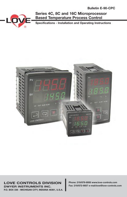
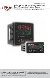
Bulletin E-90-CPC<strong>Series</strong> <strong>4C</strong>, 8C and 16C MicroprocessorBased <strong>Temperature</strong> Process ControlSpecifications - Installation and Operating InstructionsLOVE CONTROLS DIVISIONDWYER INSTRUMENTS INC.P.O. BOX 338 - MICHIGAN CITY, INDIANA 46361, U.S.A.Phone: 219/879-8000 www.love-controls.comFax: 219/872-9057 e-mail:love@love-controls.com
TABLE OF CONTENTSModel Number Identification . . . . . . . . . . . . . . . . . . . . . . . . . . . . . . 3Getting Started . . . . . . . . . . . . . . . . . . . . . . . . . . . . . . . . . . . . . . . . 3Installation. . . . . . . . . . . . . . . . . . . . . . . . . . . . . . . . . . . . . . . . . . . . 4Panel Cutout Dimensions . . . . . . . . . . . . . . . . . . . . . . . . . . . . . . . . 4Mounting. . . . . . . . . . . . . . . . . . . . . . . . . . . . . . . . . . . . . . . . . . . . . 5Wiring Diagrams . . . . . . . . . . . . . . . . . . . . . . . . . . . . . . . . . . . . . . . 6Front Panel Key Functions . . . . . . . . . . . . . . . . . . . . . . . . . . . . . . . 7Security Features . . . . . . . . . . . . . . . . . . . . . . . . . . . . . . . . . . . . . . 7Control Operation Description . . . . . . . . . . . . . . . . . . . . . . . . . . . . . 8Programming and Operation for PID Function. . . . . . . . . . . . . . . . . 9Description of Menu Structure. . . . . . . . . . . . . . . . . . . . . . . . . . . . 10Operation Menu . . . . . . . . . . . . . . . . . . . . . . . . . . . . . . . . . . . . . . 10Regulation Menu . . . . . . . . . . . . . . . . . . . . . . . . . . . . . . . . . . . 11-12Initial Setting Menu . . . . . . . . . . . . . . . . . . . . . . . . . . . . . . . . . 13-14Alarm Output Description . . . . . . . . . . . . . . . . . . . . . . . . . . . . . . . 15Communication Register List . . . . . . . . . . . . . . . . . . . . . . . . . . . . 16Communication Protocol. . . . . . . . . . . . . . . . . . . . . . . . . . . . . . . . 17Diagnostic Error Messages . . . . . . . . . . . . . . . . . . . . . . . . . . . . . . 18Reset Factory Default Setting . . . . . . . . . . . . . . . . . . . . . . . . . . . . 19Specifications . . . . . . . . . . . . . . . . . . . . . . . . . . . . . . . . . . . . . . . . 20Input Sensor Ranges . . . . . . . . . . . . . . . . . . . . . . . . . . . . . . . . . . 21Precautions. . . . . . . . . . . . . . . . . . . . . . . . . . . . . . . . . . . . . . . . . . 22External Dimensions . . . . . . . . . . . . . . . . . . . . . . . . . . . . . . . . . . . 23Page 2
MODEL NUMBER IDENTIFICATION<strong>4C</strong>8C16COUTPUT 12 = Voltage Pulse3 = Relay5 = Current6 = Linear VoltageOUTPUT 12 = Voltage Pulse3 = Relay5 = Current6 = Linear VoltageOUTPUT 12 = Voltage Pulse3 = Relay5 = Current6 = Linear VoltageGETTING STARTED1. Install the control as described on page 4.2. Wire your control following the instructions on page 6. Please readthe Precautions section located at the end of this manual before wiringthe control.3. For best results when programming changes are necessary, make allchanges to the Initial Setting mode (Pages 13-14) before makingchanges to the Regulation Mode (Pages 11-12) or Operation Mode(Pages 10). If any error messages occur, check the Diagnostic ErrorMessage Section (Page 18) for assistance.Page 3
INSTALLATIONMount the instrument in a location that will not be subject to excessivetemperature, shock, or vibration. All models are designed for mounting in anenclosed panel.Select the position desired for the instrument on the panel. Prepare thepanel by cutting and deburring the required opening per the panel cut outdimensions listed below. Follow the mounting instructions listed on page 5.Lastly, wire the controller per the appropriate wiring diagram listed on page6.PANEL CUTOUT DIMENSIONS<strong>4C</strong>8C16CPage 4
MOUNTING METHODStep 1: From the front of the panel, slide the controller housing throughthe cut out. The housing gasket should be against the housingflange before installing.Step 2:Insert the mounting brackets into the mounting grooves on thetop and bottom of the controller (<strong>4C</strong>, 8C, and 16C).Step 3: Push the mounting brackets forward until the bracket stops atthe panel wall.Step 4: Insert and tighten the screws on the bracket to secure thecontroller in place. (The screw torque should be 0.8 kgf-cm).Mounting Bracket Installation<strong>4C</strong>/8C/16C Mounting MethodPage 5
WIRINGDo not run thermocouple or other class 2 wiring in the same conduit aspower leads. Use only the type of thermocouple or RTD probe for which thecontrol has been programmed. Maintain separation between wiring ofsensor, auxiliary in or out, and other wiring. See the Initial Setting Menu forinput selection.For thermocouple input always use extension leads of the same typedesignated for your thermocouple.For supply connections use No. 16 AWG or larger wires rated for at least 75˚C. Use conductors only. All line voltage output circuits must have a commondisconnect and be connected to the same pole of the disconnect.Input wiring for thermocouple, current, and RTD; and output wiring forcurrent 14 VDC is rated CLASS 2.Control wiring as show below:Terminal IdentificationTcRTD+or-DATA +RS - 485DATA-1234567891112131415161718191020LN~AC 100 ~ 240V50 ~ 60Hz / 5VACOM3A 250VacALM2COM 3A 250VacALM1NCNO5A 250Vac-DC 4~20mA14VdcCOM+<strong>4C</strong>TcRTD+or-DATA +RS - 485DATA-1234567891112131415161718191020LN~AC 100 ~ 240V50 ~ 60Hz / 5VACOM3A 250VacALM2COM 3A 250VacALM1NCNO5A 250Vac-DC 4~20mA14VdcCOM+8C14VDC -OR4-20MAOR0-10V +OUT1NOCOM1 62 71112LNAC 100-24OV50/60/HZ5VARTD38ALM213+ +IN Tc- -4 95 10DATA+RS-485DATA-14 ALM13A250VAC15 COM3A250VAC16CPage 6
FRONT KEY FUNCTIONSKey functions are as follows:INDEX: Pressing the INDEX key advances the display to the next menuitem.UP ARROW: Increments a value or changes a menu item. If pressedduring the Operation Mode, the set point value will be increased.DOWN ARROW: Decrements a value or changes a menu item. If pressedduring the Operation Mode, the set point value will be decreased.ENTER: Stores the value or item change. If not pressed, the previouslystored value or item will be retained. When pressed during the OperationMode, the controller switches to the Regulation Mode. If held for morethan 3 seconds during the Operation Mode, the controller switches tothe Initial Setting Mode. If pressed during the Regulation Mode orInitial Setting Mode, the controller will return to the Operation Mode.SECURITY FEATURESThe C series controller has two built in security lock settings to preventunauthorized personnel from changing parameter settings. Theseparameters are set in the Operation Mode.The LoC1 setting affects all parameters in the controller. If LoC1 setting isenabled, the operator will have to unlock the controller to make any changesto the controller’s parameters.The LoC2 setting affects all parameters except the set point. If LoC2 settingis enabled, the only parameter that the operator will be able to change is theset point. In order to change any other parameters, the operator will have tounlock the control before making a change.In order to unlock the control, the operator must depress the ENTER andINDEX key simultaneously.Page 7
CONTROL OPERATION DESCRIPTIONThe HOME display is the normal display while the control is operating. If noerrors or functions are active, the HOME display will indicate the ProcessVariable that is being measured on the top display and the Set Variable onthe bottom display.Error Messages are shown on page 18.Heating or Cooling<strong>Temperature</strong> Control can be achieved by either heating or cooling. Pleaserefer to the following for the operation of each setting.Control Modes are selected by changing the S-HC parameter in the InitialSetting Mode.Select HEAt, for heating or reverse acting control for output 1.Select CooL, for cooling or direct acting control for output 1.Page 8
PROGRAMMING AND OPERATION FOR PIDTheory of OperationThe PID method of control is based on the individual tuning of proportionalband values, integral time values, and derivative time values to help a unitautomatically compensate for changes in a control system. The proportionalband is the range around the set point in which the control’s proportioningtakes place. The control increases or decreases the output proportionatelyto the process temperature’s deviation from the set point. The integral timeeliminates undershoot and overshoot of the set point by adjusting theproportioning control based on the amount of deviation from the set pointduring steady state operation. The derivative time eliminates undershoot andovershoot by adjusting the proportioning control based on the rate of rise orfall of the process temperature. The integral deviation offset correction (ioFn)improves the speed in which the process value reaches the set point value.If this parameter is set to zero, the output will be zero when the processvalue is equal to the set point value. If the integral time parameter is usedonly to eliminate steady state error, it may take a long time to reach the setpoint because it needs time to accumulate the error. This parameter definesthe default output level on start up. When the integral time is set at 0, thenthe proportional derivative offset correction (PdoF) would replace the integraldeviation offset correction, but serves the same function.Program Set UpIn order to use the PID function in the C series controllers, the Control Modewill have to be set to PID in the Initial Setting Menu. After changing theControl Mode, the PID parameters can be accessed in the Regulation Menu.The PID parameters can either be programmed manually or they can be setby the controller using the auto tune function. The auto tune will use trial anderror to tune the PID parameters to give the control the most precise control.Since the time to accurately tune the control may differ depending on theprocess, the controller can also be manually tuned to known PID valuesprior to running auto tune. The Run/Stop parameter must be set to run inorder to start auto tuning.Page 9
DESCRIPTION OF MENU STRUCTUREThe programming for the controller is broken down into three menus(Operation, Regulation, and Initial Setting). Upon normal operation, controlwill be in the Operation Menu.OPERATION MENUPressing the INDEX key will cycle through the below menu items. Theparameter will be displayed in the top display, while its value will bedisplayed in the bottom display, except for the set point which is displayedin the bottom display on the Home Display. The UP and DOWN arrowschange the values of the parameters. The ENTER key must be pressed afterany changes.1234r-SAL1HAL1LAL2HAL2LLoCoUt1rUnStoPL0C1L0C2Adjust the set point value - Can be any numerical valuebetween the upper and lower limit of the temperature range.Select Run - Stop Output Control.Activates outputs.De-activates outputs.Alarm 1 High Set Point. May not appear depending on ALA1setting in Initial Setting Menu.Alarm 1 Low Set Point. May not appear depending on ALA1setting in Initial Setting Menu.Alarm 2 High Set Point. May not appear depending on ALA2setting in Initial Setting Menu.Alarm 2 Low Set Point. May not appear depending on ALA2setting in Initial Setting Menu.Set front panel security lock.Lock all settings.Lock all settings except the set point.Display the % output value for output 1. In manual mode, thisvalue can be changed using the up and down arrows.Page 10
REGULATION MENUPress the ENTER key while at the Home Display in order to access theRegulation Menu. Pressing the INDEX key will cycle through the below menuitems. The parameter will be displayed in the top display, while its value willbe displayed in the bottom display. The UP and DOWN arrows change thevalues of the parameters. The ENTER key must be pressed after anychanges.ATAuto Tune. The controller will evaluate the process and selectthe PID values to maintain good control. Only available whenthe control mode is set to PID.onoFFPidStart learning the process. After the process has been learnedthe menu will revert to oFF.Disables Auto Tune.Proportional Band Setting.Integral time (reset time).Derivative time (rate time).PdoFioFnHtSCtSPD Offset Correction Setting. only available when controlmode is set to PID and integral time = 0. See Programmingand Operation of PID function for moving information.Integral Deviation Offset Correction associated witheach PID Profile. (n = 0 to 4).Heating Hysteresis (Differential) Setting. Sets the value for theamount of difference between the turn off point (set point) andthe turn on point. Figure A shows the output behavior for aheating (reverse acting) application. Only available whencontrol mode set to on/off control.Cooling Hysteresis (Differential) Setting. Sets the value for theamount of difference between the turn off point (set point) andthe turn on point. Figure A shows the output behavior for acooling (direct acting) application. Only available when controlmode set to on/off control.Page 11
Figure A: Output behavior for Heating/Cooling On/Off ApplicationsHtPdCLPdtPoFCrhCrLoHeating Control Cycle Setting. Defines the duration for oneoutput period or cycle for output 1. Only available when controlmode is set to PID and Output 1 is set for heating.Cooling Control Cycle Setting. Defines the duration for oneoutput period or cycle for output 1. Only available when controlmode is set to PID and Output 1 is set for cooling.Process <strong>Temperature</strong> Offset. This feature allows theinput value to be changed to agree with an externalreference or to compensate for sensor error.Analog Output High Limit: Sets the actual upper limit of theanalog output when the control’s output is operating at 100%.Only available for analog output models.Analog Output Low Limit. Sets the actual lower limit of theanalog output when the control’s output is operating at 0%.Only available for analog output models.Page 12
INITIAL SETTING MENUPress and hold the ENTER key for at least 3 seconds while at the HomeDisplay in order to access the Initial Setting Menu. Pressing the INDEX keywill cycle through the below menu items. The parameter will be displayed inthe top display, while its value will be displayed in the bottom display. TheUP and DOWN arrows change the values of the parameters. The ENTERkey must be pressed after any changes.inPtInput Selection. Select one of the following input types fromthe below table.Input <strong>Temperature</strong> Sensor Type LED Display <strong>Temperature</strong> RangeThermocouple TXK type-328 ~ 1440°F (-200 ~ 800°C)Thermocouple U type-328 ~ 932°F (-200 ~ 500°C)Thermocouple L type-328 ~ 1562°F (-200 ~ 850°C)Thermocouple B type212 ~ 3272°F (100 ~ 1800°C)Thermocouple S type32 ~ 3092°F (0 ~ 1700°C)Thermocouple R type32 ~ 3092°F (0 ~ 1700°C)Thermocouple N type-328 ~ 2340°F (-200 ~ 1300°C)Thermocouple E type32 ~ 1112°F (0 ~ 600°C)Thermocouple T type2-4 ~ 752°F (-20 ~ 400°C)Thermocouple T type1-328 ~ 752°F (-200 ~ 400°C)Thermocouple J type2-4 ~ 752°F (-20 ~ 400°C)Thermocouple J type1-148 ~ 1562°F (-100 ~ 850°C)Thermocouple K type2-4 ~ 932°F (-20 ~ 500°C)Thermocouple K type1-328 ~ 2340°F (-200 ~ 1300°C)Platinum Resistance (Pt100) type 332 ~ 212°F (0 ~ 100°C)Platinum Resistance (Pt100) type 2-4 ~ 932°F (-20 ~ 500°C)Platinum Resistance (Pt100) type 1-328 ~ 1112°F (-200 ~ 600°C)Platinum Resistance (JPt100) type 232 ~ 212°F (0 ~ 100°C)Platinum Resistance (JPt100) type 1-4 ~ 752°F (-20 ~ 400°C)tPUntP-HtP-LCtrL<strong>Temperature</strong> Units. This parameter is only available forthermocouple or RTD inputs.Scale Height Limit. Sets the upper limit of the temperaturerange. If the process temperature exceeds this setting, thedisplay will flash an error code.Scale Low Limit. Sets the lower limit of the temperature range.If the process temperature exceeds this setting, the display willflash an error code.Control Mode. Select method of control operation. Can be setto PID, On-Off, or Manual.Page 13
S-HCHeat/Cool Selection. Assigns output 1 to be either heat orcool.HEAt = Output 1 = HeatingCooL = Output 1 = CoolingALA1ALA2CoSHC-nobP5LEnPrtYStoPAlarm 1 Setting. Sets operation for Alarm 1. Please seeselection on Alarm Outputs for description of the outputs.Alarm 2 Setting. Sets operation for Alarm 2. Please seeselection on Alarm Outputs for description of the outputs.Communications Write Function Feature. Allows parametersto be changed via the RS-485 communications. Setting to oFFprevents any changes from remote users.<strong>Controller</strong> Address: Set from 1 to 247. This value must matchthe controller address used by the host computer.Baud Rate Setting. This value must match the communicationbaud rate of the host computer.Communication Data Length. Choose either 7 or 8. This valuemust match the communication data length of the hostcomputer.Communication Parity Bit. Set this value to even, odd, or none.This value must match the communication parity bit of the hostcomputer.Communication Stop Bit. Set this value to 1 or 2. This valuemust match the communication stop bit of the host computer.Page 14
Alarm Output Configuration and Operation Table.Set Value Alarm Type Alarm Output Operation0 Alarm function disabled Output is OFF1 Deviation upper- and lower-limit:This alarm output operates when PV value is higher thanthe setting value SV+(AL-H) or lower than the setting valueSV-(AL-L).2 Deviation upper-limit:This alarm output operates when PV value is higher than thesetting value SV+(AL-H).3 Deviation lower-limit:This alarm output operates when PV value is lower than thesetting value SV-(AL-L).4 Reverse deviation upper- and lower-limit:This alarm output operates when PV value is in the range ofthe setting value SV+(AL-H) and the setting value SV-(AL-L).5 Absolute value upper- and lower-limit:This alarm output operates when PV value is higher thanthe setting value AL-H or lower than the setting value AL-L.6 Absolute value upper-limit:This alarm output operates when PV value is higher thanthe setting value AL-H.7 Absolute value lower-limit:This alarm output operates when PV value is lower thanthe setting value AL-L.8 Deviation upper- and lower-limit with standby sequence:This alarm output operates when PV value reaches set point(SV value )and the value is higher than the setting valueSV+(AL-H) or lower than the setting value SV-(AL-L).9 Deviation upper-limit with standby sequence:This alarm output operates when PV value reaches set point(SV value) and the reached value is higher than thesetting value SV+(AL-H).10 Deviation lower-limit with standby sequence:This alarm output operates when PV value reaches the setpoint (SV value) and the reached value is lower than thesetting value SV-(AL-L).11 Hysteresis upper-limit alarm output:This alarm output operates if PV value is higher than thesetting value SV+(AL-H). This alarm output is OFF whenPV value is lower than the setting value SV+(AL-L).12 Hysteresis lower-limit alarm output:This alarm output operates if PV value is lower than thesetting value SV-(AL-H). This alarm output is OFF whenPV value is higher than the setting value SV-(AL-L).(Note: AL-H and AL-L include AL1H, AL2H, AL3H and AL1L, AL2L, AL3L)Page 15
Communication Register ListCommunication Parameters List<strong>Controller</strong> offers a RS-485 port for serial communication.1. Supporting transmission speed: 2400, 4800, 9600, 19200, 38400 bps.2. Communication protocol: Modbus (ASCII).3. Non-supported formats: 7, N, 1 or 8, O, 2 or 8, E, 2.4. Available communication address: 1 to 255, 0 is broadcast address.5. Function code: 03H to read the contents of register (Max. 3 words).6. 06H to write 1 (one) word into register.Address Content Explanation4700H (R) Process value (PV)Measuring unit is 0.1, updated one timein 0.5 second.4701H Set point (SV) Unit is 0.1, oC or oF4702H Upper-limit alarm 14703H Lower-limit alarm 14704H Upper-limit alarm 24705H Lower-limit alarm 24706H Upper-limit of temperature range The data content should not be higher thanthe temperature range4707H Lower-limit of temperature range The data content should not be lower thanthe temperature range4708H PB Proportional band 0.1 to 999.9, unit is 0.14709H Ti Integral time 0 to 9999470AH Td Derivative time 0 to 9999470BH Heating/Cooling hysteresis 0 to 9999470CH ~ 470FHReserved4710H Input temperature sensor type Please refer to the contents of the“<strong>Temperature</strong> Sensor Type and <strong>Temperature</strong>Range” for detail4711H Control method 0: PID (default), 1: ON/OFF, 2: manual tuning4712H Heating/Cooling control cycle 1 to 99 second4713H Proportional control 0% to 100%offset error value4714H <strong>Temperature</strong> regulation value -999 ~ 999, unit: 0.14715H Alarm 1 type Please refer to the contents of the “AlarmOutputs” for detail4716H Alarm 2 type Please refer to the contents of the “AlarmOutputs” for detail4717H <strong>Temperature</strong> unit display selection oC: 1 (default), oF: 04718H Heating/Cooling control Selection Heating: 0 (default), Cooling: 14719H Control Run/Stop setting Run: 1 (default), Stop: 0471AH Communication write-in selection Communication write in disabled: 0 (default),Communication write in enabled: 1471BH Software version W1.00 indicates 0 x 1004729H AT Setting OFF: 0 (default), ON:1Code 0Code 1Code 2Code 3472BH (R) Code <strong>4C</strong>ode 5Code 6Code 74733H CT monitor value Unit is 0.1ANote: R means “read only” valuePage 16Normal operation (No error)Initial processInitial status (<strong>Temperature</strong> is not stable)<strong>Temperature</strong> sensor is not connected<strong>Temperature</strong> sensor input errorMeasured temperature value exceedsthe temperature rangeNo Int. errorEEPROM Error
Communication ProtocolCommand code to read N words: 03H. The maximum value of N is 3.For example, in order to read two words from controller 01 (address 01H) atstarting data address 4700H, the command in ASCII mode is:ASCII mode:Command message:STXADR1ADR0CMD1CMD0StartingdataaddressNumber of data(count by word)LRC CHK 1LRC CHK 0END 1END 0‘:’‘0’‘1’‘0’‘3’‘4’‘7’‘0’‘0’‘0’‘0’‘0’‘2’‘B’‘3’CRLFResponse message:STXADR1ADR0CMD1CMD0Number of data(count by byte)Content of startaddress 4700HContent of startaddress 4700HLRC CHK 1LRC CHK 0END 1END 0‘:’‘0’‘1’‘0’‘3’‘0’‘4’‘0’‘1’‘9’‘0’‘0’‘0’‘0’‘0’‘6’‘7’CRLFLRC check:LRC check is the added sum from “Address” to Data content”. For example,01H + 03H + 47H + 00H + 00H + 02H = 4DH, then take the complementaryof 2, B3H.Command code to write 1 word: 06HFor example, in order to write 1000 (03E8H) in controller 01 (comm. address01H) at starting data address 4701H, the command is ASCII mode is:ASCII mode:Command message:STXADR1ADR0CMD1CMD0StartingdataaddressData ContentLRC CHK 1LRC CHK 0END 1END 0‘:’‘0’‘1’‘0’‘6’‘4’‘7’‘0’‘1’‘0’‘3’‘E’‘8’‘C’‘6’CRLFResponse message:STXADR1ADR0CMD1CMD0StartingdataaddressesData ContentLRC CHK 1LRC CHK 0END 1END 0‘:’‘0’‘1’‘0’‘6’‘4’‘7’‘0’‘1’‘0’‘3’‘E’‘8’‘C’‘6CRLFPage 17
DIAGNOSTIC ERROR MESSAGESDisplay Error MessagesDisplayPVSVPVSVPVSVPVSVPVSVb150rrNoContErrinPt20010.0ErrPronDescriptionDisplay on Start UpNo Input Probe ConnectionInput ErrorProcess Value Flasheswhen outside of rangeError EEPROMAction RequiredNo Action RequiredVerify that sensor is wired to properterminals. Next, check that the controlleris programmed for the correct input type.Most commonly seen when controller isprogrammed for a RTD, while athermocouple is connected.Verify that the input is wired to the properterminals. Next check to see if the inputtype is set to the proper value. Mostcommonly seen when controller isprogrammed for a 4 to 20 mA input and0 to 20 mA signal is wired to thecontroller.Input signals may normally go above orbelow range limits. If not check input andcorrect the process temperature orincrease temperature range limits usingtP-H and tP-L.Attempt to reset the factory defaultsettings using the instructions in the nextsection. If still has error, call customerservice for a return goods authorizationnumber to have the controller evaluatedat the factory.Communication Error MessagesError Status102EH/4750H0001H0002H0003H0004H0005H0006H0007HPV read back1000H/4700HN/A8002H8003H8004HN/A8006HN/AError StatusPV UnstableRe-initialize, no temperature at this timeInput sensor did not connectInput Signal ErrorOver Input RangeADC failEEPROM read/write errorPage 18
Reset Factory Default SettingsNote: Resetting Factory Default Settings erases all of the values entered bythe user. Record any necessary settings before proceeding.Warning: Erasing the user entered values may result in a safety hazard andsystem malfunction.The following instructions will reset the controller to the original factorydefault settings.Step 1.Step 2.Step 3.Step 4.Press the INDEX KEY while at the Home Display until thecontroller reads LoC in the process display. Use the UParrow to select LoC1. Press the ENTER KEY to save thisvalue.Press and hold the UP and DOWN arrowssimultaneously for one second. Upon releasing thebuttons, the display will read SHou in the PV displayand oFF in the SV display.Press the INDEX key once and the controller will readPASS in the PV display and a 4321 in the SV display.Adjust the value in the SV display to 1357 using the UPnd DOWN arrows. Press the ENTER KEY to save the value.Cycle the power on the controller. Upon power up, all of theuser set values have been erased.Page 19
SPECIFICATIONSInput VoltageOperation Voltage RangePower ConsumptionMemory ProtectionDisplay MethodSensor TypeControl ModeControl OutputDisplay AccuracySampling RangeRS-485 CommunicationVibration ResistanceShock ResistanceAmbient <strong>Temperature</strong>Storage <strong>Temperature</strong>AltitudeRelative Humidity100 to 240VAC 50/60Hz.85% to 110% of rated voltage.5VA max.EEPROM 4K bit (non-volatile memory(number of writes: 100,000).2 line x 4 character 7-segment LED display.Process value (PV): Red color, Set point (SV): Green color.Thermocouple: K, J, T, E, N, R, S, B, L, U, TXK.3-wire Platinum RTD: Pt100, JPt100.PID, ON/OFF, or Manual.Relay output: SPDT (SPST: 1/16 DIN). Max.600.Voltage pulse output: DC 14V, Max. output current 40mA.Current output: DC 4 ~ 20mA output(Load resistance: Max. 600Ω).0.1% of measuring range.Thermocouple or Platinum RTD: 500 msec/per scan.MODBUS ASCII communication protocol10 to 55 Hz, 10 m/s 2 for 10 min, each in X, Y and Z direction.Max. 300 m/s2, 3 times in each 3 axes, 6 directions32°F to 122°F (0°C to + 50°C)-4°F to 150°F (-20°C + 65°C)2000 m or less0% to 80% (non-condensing)Page 20
Thermocouple Type and <strong>Temperature</strong> RangeInput <strong>Temperature</strong> Sensor Type LED Display <strong>Temperature</strong> RangeThermocouple TXK type-328 ~ 1440°F (-200 ~ 800°C)Thermocouple U type-328 ~ 932°F (-200 ~ 500°C)Thermocouple L type-328 ~ 1562°F (-200 ~ 850°C)Thermocouple B type212 ~ 3272°F (100 ~ 1800°C)Thermocouple S type32 ~ 3092°F (0 ~ 1700°C)Thermocouple R type32 ~ 3092°F (0 ~ 1700°C)Thermocouple N type-328 ~ 2340°F (-200 ~ 1300°C)Thermocouple E type32 ~ 1112°F (0 ~ 600°C)Thermocouple T type2-4 ~ 752°F (-20 ~ 400°C)Thermocouple T type1-328 ~ 752°F (-200 ~ 400°C)Thermocouple J type2-4 ~ 752°F (-20 ~ 400°C)Thermocouple J type1-148 ~ 1562°F (-100 ~ 850°C)Thermocouple K type2-4 ~ 932°F (-20 ~ 500°C)Thermocouple K type1-328 ~ 2340°F (-200 ~ 1300°C)RTD Type and <strong>Temperature</strong> RangeInput <strong>Temperature</strong> Sensor Type LED Display <strong>Temperature</strong> RangePlatinum Resistance (Pt100) type 332 ~ 212°F (0 ~ 100°C)Platinum Resistance (Pt100) type 2-4 ~ 932°F (-20 ~ 500°C)Platinum Resistance (Pt100) type 1-328 ~ 1112°F (-200 ~ 600°C)Platinum Resistance (JPt100) type 232 ~ 212°F (0 ~ 100°C)Platinum Resistance (JPt100) type 1-4 ~ 752°F (-20 ~ 400°C)Page 21
PRECAUTIONSDANGER! Caution! Electric Shock!1. Do not touch the AC terminals while the power is supplied to the controllerto prevent an electric shock.2. Make sure power is disconnected while checking the unit inside.3. The symbol indicates that this <strong>Controller</strong> is protected throughout byDOUBLE INSULATION or REINFORCED INSULATION (equivalent to Class IIof IEC 536).WARNING!Mount the controller in a location that will not be subject to excessivetemperature, shock, or vibration. All models are designed for mounting in anenclosed panel.1. Always use recommended solder-less terminals: Fork terminals with isolation(M3 screw, width is 7.0mm (6.0mm for 32B <strong>Series</strong>), hole diameter 3.2mm).Screw size: M3 x 6.5 (With 6.8 x 6.8 square washer). Screw size for 32B<strong>Series</strong>: M3 x 4.5 (With 6.0 x 6.0 square washer). Recommended tighteningtorque: 0.4 N.m (4kgf.cm). Applicable wire: Solid/twisted wire of 2 mm 2 ,12AWG to 24AWG. Please be sure to tighten them properly.2. Do not allow dust or foreign objects to fall inside the controller to prevent itfrom malfunctioning.3. Never modify or disassemble the controller.4. Do not connect anything to the “No used” terminals.5. Make sure all wires are connected to the correct polarity of terminals.6. Do not install and/or use the controller in places subject to: Dust or corrosivegases and liquid, high humidity and high radiation, vibration and shock, highvoltage and high frequency.7. Power must be off when wiring and changing a temperature sensor.8. Be sure to use compensating wires that match the thermocouple types whenextending or connecting the thermocouple wires.9. Please use wires with resistance when extending or connecting a platinumresistance sensor (RTD).10. Please keep the wire as short as possible when wiring a platinum resistancesensor (RTD) to the controller and please route power wires as far aspossible from load wires to prevent interference and induce noise.11. This controller is an open-type unit and must be placed in an enclosure awayfrom high temperature, humidity, dripping water, corrosive materials, airbornedust and electric shock or vibration.12. Please make sure power cables and signals from instruments are all installedproperly before energizing the controller, otherwise serious damage mayoccur.13. Please do not use acid or alkaline liquids for cleaning. Please use a soft, drycloth to clean the controller.14. Wait at least one minute after power is disconnected to allow capacitors todischarge, and please do not touch any internal circuit within this period.15. This instrument is not furnished with a power switch or fuse. Therefore, if afuse or power switch is required, install the protection close to theinstrument. Recommended fuse rating: Rated voltage 250 V, Rated current1 A. Fuse type: Time-lag fuse.16. Note: This controller does not provide overcurrent protection. Use of theproduct requires that suitable overcurrent protection device(s) must beadded to ensure compliance with all relevant electrical standards and codes.(Rated 250 V, 15 Amps max). A suitable disconnecting device should beprovided near the controller in the end-use installation.Page 22
External DimensionsDimensions are in millimeter (inch)<strong>4C</strong>8C16CPage 23
©Copyright 2010 Dwyer Instruments, Inc. Printed in U.S.A. 3/10 FR# R5-443601-20 Rev. 2LOVE CONTROLS DIVISIONDWYER INSTRUMENTS INC.P.O. BOX 338 - MICHIGAN CITY, INDIANA 46361, U.S.A.Phone: 219/879-8000 www.love-controls.comFax: 219/872-9057 e-mail:love@love-controls.com


