paediGAV - Christoph Miethke GmbH & Co. KG
paediGAV - Christoph Miethke GmbH & Co. KG
paediGAV - Christoph Miethke GmbH & Co. KG

You also want an ePaper? Increase the reach of your titles
YUMPU automatically turns print PDFs into web optimized ePapers that Google loves.
Instructions for use<br />
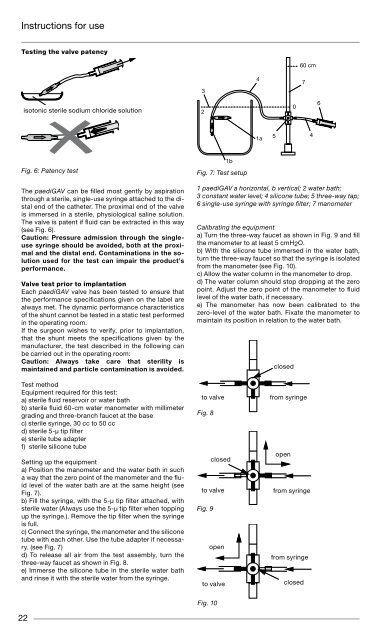
Testing the valve patency<br />
22<br />
isotonic sterile sodium chloride solution<br />
Fig. 6: patency test Fig. 7: Test setup<br />
The <strong>paediGAV</strong> can be filled most gently by aspiration<br />
through a sterile, single-use syringe attached to the distal<br />
end of the catheter. The proximal end of the valve<br />
is immersed in a sterile, physiological saline solution.<br />
The valve is patent if fluid can be extracted in this way<br />
(see Fig. 6).<br />
Caution: Pressure admission through the singleuse<br />
syringe should be avoided, both at the proximal<br />
and the distal end. <strong>Co</strong>ntaminations in the solution<br />
used for the test can impair the product’s<br />
performance.<br />
Valve test prior to implantation<br />
Each <strong>paediGAV</strong> valve has been tested to ensure that<br />
the performance specifications given on the label are<br />
always met. The dynamic performance characteristics<br />
of the shunt cannot be tested in a static test performed<br />
in the operating room.<br />
If the surgeon wishes to verify, prior to implantation,<br />
that the shunt meets the specifications given by the<br />
manufacturer, the test described in the following can<br />
be carried out in the operating room:<br />
Caution: Always take care that sterility is<br />
maintained and particle contamination is avoided.<br />
Test method<br />
Equipment required for this test:<br />
a) sterile fluid reservoir or water bath<br />
b) sterile fluid 60-cm water manometer with millimeter<br />
grading and three-branch faucet at the base<br />
c) sterile syringe, 30 cc to 50 cc<br />
d) sterile 5-µ tip filter<br />
e) sterile tube adapter<br />
f) sterile silicone tube<br />
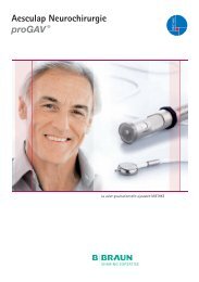
Setting up the equipment<br />
a) Position the manometer and the water bath in such<br />
a way that the zero point of the manometer and the fluid<br />
level of the water bath are at the same height (see<br />
Fig. 7).<br />
b) Fill the syringe, with the 5-µ tip filter attached, with<br />
sterile water (Always use the 5-µ tip filter when topping<br />
up the syringe.). Remove the tip filter when the syringe<br />
is full.<br />
c) <strong>Co</strong>nnect the syringe, the manometer and the silicone<br />
tube with each other. Use the tube adapter if necessary.<br />
(see Fig. 7)<br />
d) To release all air from the test assembly, turn the<br />
three-way faucet as shown in Fig. 8.<br />
e) Immerse the silicone tube in the sterile water bath<br />
and rinse it with the sterile water from the syringe.<br />
3<br />
2<br />
1 <strong>paediGAV</strong> a horizontal, b vertical; 2 water bath;<br />
3 constant water level; 4 silicone tube; 5 three-way tap;<br />
6 single-use syringe with syringe filter; 7 manometer<br />
Calibrating the equipment<br />
a) Turn the three-way faucet as shown in Fig. 9 and fill<br />
the manometer to at least 5 cmH2O.<br />
b) With the silicone tube immersed in the water bath,<br />
turn the three-way faucet so that the syringe is isolated<br />
from the manometer (see Fig. 10).<br />
c) Allow the water column in the manometer to drop.<br />
d) The water column should stop dropping at the zero<br />
point. Adjust the zero point of the manometer to fluid<br />
level of the water bath, if necessary.<br />
e) The manometer has now been calibrated to the<br />
zero-level of the water bath. Fixate the manometer to<br />
maintain its position in relation to the water bath.<br />
to valve<br />
Fig. 8<br />
1b<br />
closed<br />
to valve<br />
Fig. 9<br />
open<br />
to valve<br />
Fig. 10<br />
4<br />
1a<br />
5<br />
closed<br />
0<br />
60 cm<br />
7<br />
from syringe<br />
open<br />
from syringe<br />
from syringe<br />
closed<br />
4<br />
6<br />
Test procedure<br />
Please note: During the test the shunt must be<br />
submerged in the water bath. The zero point of<br />
the manometer has to be aligned with the water<br />
level of the water bath in order to obtain correct<br />
results.<br />
a) <strong>Co</strong>nnect the sterile shunt to be tested to the ready<br />
assembled, sterile test equipment.<br />
b) Turn the three-way faucet as shown in Fig. 9 and fill<br />
the manometer to 10 cmH2O above the expected opening<br />
pressure. (Example: For testing a <strong>paediGAV</strong> with<br />
an opening pressure setting of 5 cmH2O horizontal and<br />
25 cmH2O vertical, the manometer is filled to 15 cm-<br />
H2O with the shunt in a horizontal position and to 40<br />
cmH2O with the shunt in a vertical position.)<br />
c) Turn the three-way faucet as shown in Fig. 8 so that<br />
the manometer is isolated.<br />
d) Remove all air from the shunt and the test setup by<br />
carefully rinsing it through with sterile water from the<br />
syringe.<br />
e) Immerse the sterile shunt in the sterile water bath.<br />
The distal part of the shunt must be under water to obtain<br />
valid test results.<br />
f) Carefully maintain a flow through the shunt and turn<br />
the three-way faucet as shown in Fig. 10 to isolate the<br />
syringe. As soon as the three-way faucet is in the correct<br />
position, the water column should begin to drop.<br />
The syringe is now isolated from the valve and it is not<br />
necessary anymore to maintain its flow. Repeat steps b<br />
to f if the water column fails to drop.<br />
g) Allow the water level in the manometer to drop for<br />
2 to 2.5 minutes. Read the resulting pressure at the<br />
manometer.<br />
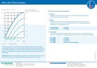
Test results of preimplantation test<br />
The pressure readings obtained by this method should<br />
yield the following results:<br />
Opening pressure<br />
cmH2O<br />
horizontal valve position<br />
Acceptable pressure<br />
range<br />
4 cmH2O 1-6 cmH2O<br />
9 cmH2O 4-12 cmH2O<br />
Opening pressure<br />
cmH2O<br />
vertical valve position<br />
Acceptable pressure<br />
range<br />
14 cmH2O 5-14 cmH2O<br />
19 cmH2O 9-19 cmH2O<br />
24 cmH2O 12-24 cmH2O<br />
29 cmH2O 15-29 cmH2O<br />
Instructions for use<br />
Test on reflow safety<br />
This test is carried out with the same equipment as<br />
the preimplantation test. The shunt is carefully filled<br />
with sterile saline solution from the syringe before the<br />
air is removed from it (Fig. 11). The shunt is connected<br />
against the direction of flow (see arrow on the shunt).<br />
The outlet of the shunt has to be at the zero level of the<br />
manometer. The manometer is filled up to 14 cmH2O<br />
(Fig. 12).<br />
The three-way faucet is used for unblocking the flow to<br />
the shunt and blocking the flow to syringe. In this setup,<br />
no more than 2 drops (0.1 cc) per minute should emerge<br />
from the proximal part of the shunt (Fig. 13).<br />
Fig. 11<br />
Fig. 12<br />
Fig. 13<br />
isotonic sterile sodium<br />
chloride solution<br />
0-level<br />
0-level<br />
closed<br />
open<br />
14 cm<br />
open<br />
14 cm<br />
closed<br />
Caution: Be careful to maintain sterility and to<br />
avoid particle contamination.<br />
Reimplantation<br />
Under no circumstances should products that have<br />
had previously been implanted in a patient be subsequently<br />
reimplanted in another, as a validated decontamination<br />
process will compromise the functionality<br />
of the valve.<br />
Safety measures<br />
The patients must be carefully monitored after the<br />
implantation. Reddened skin and tension in the area<br />
of the drainage tissue could indicate infections at the<br />
SHunTSySTem. Symptoms such as headache, dizzy<br />
spells, mental confusion or vomiting are common occurrences<br />
in cases of shunt dysfunction. Such symptoms,<br />
as well as shunt system leakage, necessitate<br />
the immediate replacement of the shunt component<br />
responsible, or of the entire SHunTSySTem.<br />
23