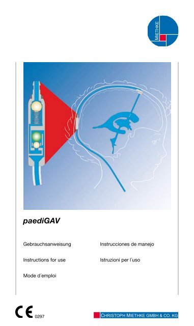
paediGAV - Christoph Miethke GmbH & Co. KG
paediGAV - Christoph Miethke GmbH & Co. KG
paediGAV - Christoph Miethke GmbH & Co. KG

Create successful ePaper yourself
Turn your PDF publications into a flip-book with our unique Google optimized e-Paper software.
<strong>paediGAV</strong><br />
Gebrauchsanweisung<br />
Instructions for use<br />
Mode d´emploi<br />
0297<br />
Instrucciones de manejo<br />
Istruzioni per l´uso<br />
MIETHKE<br />
CHRISTOPH MIETHKE GMBH & CO. <strong>KG</strong>
Inhaltsverzeichnis<br />
Indikation<br />
Technische Beschreibung<br />
Physikalischer Hintergrund<br />
Arbeitsweise des <strong>paediGAV</strong><br />
Auswahl des geeigneten <strong>paediGAV</strong><br />
Mögliche Shuntkomponenten<br />
Schlauchsysteme<br />
Operationsablauf<br />
Überprüfung der Durchgängigkeit des Ventils<br />
Ventiltest vor der Implantation<br />
Test zur Rückflusssicherheit<br />
Druck-Flow-Charakteristik<br />
Wiederholungsimplantationen<br />
Vorsichtsmaßnahmen<br />
Verträglichkeit mit diagnostischen Verfahren<br />
Postoperative Ventilprüfung<br />
Funktionssicherheit<br />
Sterilisation<br />
Erneute Sterilisation<br />
Medizinprodukteberater<br />
Forderungen der Medizinprodukterichtlinie<br />
RL 93/42/EEC<br />
Kommentar zur Gebrauchsanweisung<br />
Allgemeine Informationen<br />
Varianten<br />
Gebrauchsanweisung<br />
4<br />
4<br />
5<br />
6<br />
7<br />
8<br />
8<br />
9<br />
10<br />
10<br />
11<br />
12<br />
13<br />
13<br />
13<br />
13<br />
13<br />
13<br />
13<br />
13<br />
13<br />
13<br />
13<br />
14<br />
3
4<br />
Gebrauchsanweisung<br />
Indikation<br />
Das <strong>paediGAV</strong> dient beim pädiatrischen<br />
Hydrocephalus zur Liquordrainage aus<br />
den Ventrikeln in das Peritoneum.<br />
Technische Beschreibung<br />
Das <strong>paediGAV</strong> ist ein lageabhängig arbeitendes<br />
Ventil für die Behandlung des<br />
pädiatrischen Hydrocephalus. Es besteht<br />
aus einem Kugel-Konus-Ventil und einem<br />
Gravitationsventil. Auf diese Weise kann in<br />
jeder Körperposition eine physiologische<br />
Drainage sichergestellt werden.<br />
Gravitations-Ventil<br />
Kugel-Konus-Ventil<br />
Abb. 1 zeigt eine schematische Querschnittszeichnung<br />
des <strong>paediGAV</strong>. Das<br />
<strong>paediGAV</strong> besteht aus einem stabilen Titangehäuse,<br />
in dessen proximalem Teil ein<br />
bewährtes Kugel-Konus-Ventil integriert<br />
ist. Eine Spiralfeder (2) gewährleistet den<br />
Öffnungsdruck des Kugel-Konus-Ventils.<br />
Das Gravitationsventil im distalen Bereich<br />
besteht aus der Tantalkugel (3), die den<br />
Öffnungsdruck dieses Ventils bestimmt<br />
und der Saphirkugel (1), die den präzisen<br />
Verschluss garantiert. Am distalen Ventilende<br />
ist optional ein Konnektor oder ein<br />
Silikonkatheter integriert.<br />
1 Saphirkugel<br />
2 Spiralfeder<br />
3 Tantalkugel<br />
Abb. 1: Schematische Querschnittszeichnung<br />
des <strong>paediGAV</strong><br />
1<br />
2<br />
3<br />
1<br />
IVP Intraventrikulärer Druck<br />
PVli Ventilöffnungsdruck im Liegen<br />
(nur Kugel-Konusventil)<br />
PVst Ventilöffnungsdruck im Stehen<br />
(Kugel-Konusventil + Gravitationsventil)<br />
PB Druck in der Bauchhöhle<br />
PHyd Hydrostatischer Druck<br />
Liegend: IVP = PVli + PB<br />
Stehend: IVP = PHyd - PVst - PB<br />
IVP<br />
PVli<br />
PB<br />
Physikalischer Hintergrund<br />
In der liegenden Körperposition ist der<br />
intraventrikuläre Druck beim gesunden<br />
Menschen positiv. Um diesen Druck mittels<br />
Ventildrainage einzustellen, ist nur der<br />
Bauchraumdruck zu beachten.<br />
In der stehenden Körperposition wird ein<br />
leicht negativer Ventrikeldruck angestrebt.<br />
Um diesen Druck mittels Ventildrainage<br />
einzustellen, muss der Ventilöffnungsdruck<br />
in dieser Körperposition weit höher<br />
Gebrauchsanweisung<br />
PHyd<br />
Abb. 2: Berechnung des intraventrikulären Drucks für die liegende und die aufrechte<br />
Körperposition<br />
IVP<br />
PVst<br />
PB<br />
ausgelegt werden, als in er liegenden Position<br />
nötig wäre. Nur dann kann das Ventil<br />
den hydrostatischen Druck abzüglich des<br />
Bauchraumdrucks kompensieren.<br />
Konventionelle Ventile öffnen in der aufrechten<br />
Körperposition sofort und es kann<br />
zu einer kritischen Überdrainage kommen<br />
(siehe Abb. 2).<br />
5
6<br />
Gebrauchsanweisung<br />
Arbeitsweise des <strong>paediGAV</strong><br />
Die prinzipielle Arbeitsweise des paedi-<br />
GAV ist in Abb. 3 und Abb. 4 dargestellt.<br />
Abb. 3a zeigt das <strong>paediGAV</strong> in horizontaler<br />
Position. Das Kugel-Konus-Ventil ist<br />
geschlossen und es ist so keine Drainage<br />
möglich. In Abb. 3b ist das <strong>paediGAV</strong> in<br />
geöffnetem Zustand abgebildet.<br />
a)<br />
b)<br />
Abb. 3: <strong>paediGAV</strong> in der horizontalen<br />
Körperposition<br />
Der IVP des Kindes ist erhöht und die<br />
Federkraft, die das Kugel-Konus-Ventil<br />
sonst geschlossen hält, ist überwunden.<br />
Die Verschlusskugel bewegt sich aus dem<br />
Konus und ein Spalt zur Liquordrainage<br />
wird freigegeben. Das Gravitationsventil<br />
ist in der Liegendposition immer geöffnet<br />
und stellt keinen Widerstand dar.<br />
a) b)<br />
Abb. 4: <strong>paediGAV</strong> in der vertikalen<br />
Körperposition<br />
In dem Moment, in dem sich das Kind<br />
aufrichtet, schließt das Gravitationsventil<br />
und die Liquordrainage wird unterbrochen<br />
(Abb. 4a). Erst wenn die Summe aus<br />
IVP und hydrostatischem Druck den Öffnungsdruck<br />
des Kugel-Konus-Ventils und<br />
die Gewichtskraft der Tantalkugel des<br />
Gravitationsventils übersteigt, ist eine Liquordrainage<br />
wieder möglich (Abb. 4b).<br />
Auswahl des geeigneten <strong>paediGAV</strong><br />
Das <strong>paediGAV</strong> ist ein lageabhängig arbeitendes<br />
Ventil. Es besitzt zwei verschiedene<br />
Öffnungsdrücke. Ein Öffnungsdruck ist für<br />
die horizontale, der andere Öffnungsdruck<br />
für die vertikale Körperposition des Patienten<br />
ausgelegt. Ein perkutanes Verstellen<br />
des Ventilöffnungsdrucks kann auf diese<br />
Weise vermieden werden, da ein hoher<br />
Öffnungsdruck in der vertikalen Körperposition<br />
einer ungewollt hohen Drainage<br />
entgegenwirkt, im Liegen jedoch der erforderlich<br />
niedrige Öffnungsdruck eine Unterdrainage<br />
ausschließt.<br />
Gebrauchsanweisung<br />
Horizontale Körperposition:<br />
Für die horizontale Körperposition stehen<br />
zwei verschiedene Öffnungsdrücke zur<br />
Verfügung (4 und 9 cmH2O). Hier sollte<br />
je nach Indikation (Alter des Kindes) eine<br />
Druckstufe ausgewählt werden.<br />
Vertikale Körperposition:<br />
Der Öffnungsdruck für die vertikale Körperposition<br />
ist abhängig von der Größe des<br />
Kindes (Hydrostatik). Wird ein Säugling behandelt,<br />
sollte eine niedrigere Druckstufe<br />
gewählt werden, bei einem größeren Kind<br />
kann ein <strong>paediGAV</strong> mit einer höheren<br />
Druckstufe verwendet werden.<br />
Jedes <strong>paediGAV</strong> wird unter strenger Qualitätskontrolle kalibriert. Folgende Druckstufenkombinationen<br />
sind erhältlich:<br />
Öffnungsdruck cmH2O<br />
horizontal vertikal<br />
Kodierung im<br />
Röntgenbild<br />
Standarddruckstufen<br />
Empfehlung<br />
4 24 jünger als 6 Monate<br />
9 24<br />
zwischen<br />
6 Monaten und 5 Jahren<br />
9 29 älter als 5 Jahre<br />
4 14<br />
4 19<br />
9 19<br />
Sonderdruckstufen<br />
Abb. 5 Druckstufenempfehlung (siehe www.miethke.com)<br />
Röntgenaufnahme<br />
des<br />
<strong>paediGAV</strong><br />
(9/24 cmH2O)<br />
7
8<br />
Gebrauchsanweisung<br />
Mögliche Shuntkomponenten<br />
Das <strong>paediGAV</strong> kann in verschiedenen Varianten<br />
bestellt werden. Diese Shuntvarianten<br />
besitzen unterschiedliche Komponenten,<br />
die nachfolgend kurz vorgestellt<br />
werden.<br />
Das SprunG reSerVoir oder das<br />
Bohrlochreservoir werden im Bohrloch<br />
der Schädeldecke positioniert und bieten<br />
die Möglichkeit, den intraventrikulären<br />
Druck zu messen, Medikamente zu<br />
injizieren und Liquor zu entnehmen. Ein<br />
stabiler Titanboden verhindert ein mögliches<br />
Durchstechen des Bodens. Das<br />
SprunG reSerVoir ermöglicht zusätzlich<br />
durch ein Rückschlagventil im Boden<br />
den Liquor in die ableitende Richtung zu<br />
pumpen und damit sowohl eine Kontrolle<br />
des distalen Drainageanteils (Reservoir<br />
schwer ausdrückbar), als auch des Ventrikelkatheters<br />
(Reservoir füllt sich nach<br />
Ausdrücken nicht erneut) durchzuführen.<br />
Während des Pumpvorgangs ist der Zugang<br />
zum Ventrikelkatheter verschlossen.<br />
Der Öffnungsdruck des SHunTSySTemS<br />
wird durch den Einsatz des SprunG re-<br />
SerVoirS nicht erhöht.<br />
Das <strong>Co</strong>nTrol reSerVoir oder die<br />
pädiatrische Vorkammer werden auf der<br />
Schädeldecke positioniert und bieten als<br />
Vorkammer die Möglichkeit, den intraventrikulären<br />
Druck zu messen, Medikamente<br />
zu injizieren, Liquor zu entnehmen<br />
und eine palpatorische Ventilkontrolle<br />
durchzuführen. Ähnlich dem SprunG<br />
reSerVoir besitzt das <strong>Co</strong>nTrol<br />
reSerVoir ein Rückschlagventil. Der<br />
stabiler Titanboden verhindert ein mögliches<br />
Durchstechen des Bodens. Eine<br />
Punktion sollte möglichst senkrecht zur<br />
Reservoiroberfläche mit einer Kanüle von<br />
max. Ø 0.9 mm erfolgen. Es kann ohne<br />
Einschränkung 30 mal punktiert werden.<br />
Warnhinweis: Durch häufiges Pumpen<br />
kann es zu einer übermäßigen Drainage<br />
und damit zu unphysiologischen<br />
Druckverhältnissen kommen. Der Patient<br />
sollte über diese Gefahr aufgeklärt<br />
werden.<br />
Wird ein Bohrlochumlenker verwendet,<br />
bietet sein strammer Sitz auf dem Ventrikelkatheter<br />
die Möglichkeit, die in den<br />
Schädel eindringende Katheterlänge vor<br />
der Implantation zu wählen. Der Ventrikelkatheter<br />
wird dann im Bohrloch rechtwinklig<br />
umgelenkt. (siehe Operationsablauf).<br />
Schlauchsysteme<br />
Das <strong>paediGAV</strong> ist so konstruiert, dass es<br />
nach Indikation des Arztes den optimalen<br />
Ventrikeldruck sicherstellt. Es kann als<br />
<strong>paediGAV</strong>-SHunTSySTem oder als einzelne<br />
Ven tileinheit mit oder ohne integriertem<br />
distalen Katheter (Innendurchmesser<br />
1,2 mm, Außendurchmesser 2,5<br />
mm) bestellt werden. Wird kein Shuntsystem<br />
eingesetzt, sollten Katheter mit<br />
einem Innendurchmesser von ca. 1,2 mm<br />
und einem Außendurchmesser von ca.<br />
2,5 mm verwendet werden. Der Konnektor<br />
am Ventil ermöglicht die Verwendung<br />
von Kathetern mit einem Innendurchmesser<br />
von 1,0 mm bis 1,5 mm. Der Außendurchmesser<br />
des Katheters sollte<br />
etwa dem doppelten Innendurchmesser<br />
entsprechen. In jedem Fall müssen die<br />
Katheter durch eine Ligatur sorgfältig an<br />
den Konnektoren des Ventils befestigt<br />
werden. Knicke in den Kathetern müssen<br />
vermieden werden.<br />
Die mitgelieferten Katheter verändern die<br />
Druck-Flow-Charakteristik nicht grundlegend.<br />
Operationsablauf<br />
platzierung Ventrikelkatheter<br />
Zur Platzierung des Ventrikelkatheters<br />
sind verschiedene Operationstechniken<br />
möglich:<br />
Der notwendige Hautschnitt sollte bevorzugt<br />
entweder in Form eines Läppchens<br />
mit Stielung in Richtung auf den ableitenden<br />
Katheter oder durch einen geraden<br />
Hautschnitt erfolgen. Es sollte darauf<br />
geachtet werden, dass nach Anlage des<br />
Bohrlochs die Öffnung der Dura möglichst<br />
klein erfolgt, um ein Liquorleck zu vermeiden.<br />
Der Ventrikelkatheter wird durch den<br />
beiliegenden Mandrin versteift.<br />
Das <strong>paediGAV</strong> ist in verschiedenen Shuntvarianten<br />
erhältlich:<br />
Bei Verwendung des <strong>paediGAV</strong>-SHunT-<br />
SySTemS mit Bohrlochreservoir wird<br />
zuerst der Ventrikelkatheter implantiert.<br />
Nach dem Entfernen des Mandrins kann<br />
die Durchgängigkeit des Ventrikelkatheters<br />
durch Heraustropfen von CSF geprüft<br />
werden. Der Katheter wird gekürzt und<br />
das Bohrlochreservoir konnektiert, wobei<br />
die Konnektion mit einer Ligatur gesichert<br />
wird. Der Hautschnitt sollte nicht unmittelbar<br />
über dem Reservoir liegen.<br />
Bei der Verwendung eines <strong>paediGAV</strong>-<br />
SHunTSySTemS mit Vorkammer liegt<br />
ein Bohrlochumlenker bei. Mit Hilfe dieses<br />
Umlenkers kann die zu implantierende<br />
Katheterlänge eingestellt werden. Der<br />
Ventrikelkatheter wird in den Ventrikel vorgeschoben,<br />
umgelenkt und die Vorkammer<br />
platziert. Durch eine postoperative<br />
CT-oder MR-Aufnahme sollte die Positionierung<br />
des Ventrikelkatheters nochmals<br />
überprüft werden.<br />
Instrucciones de manejo<br />
platzierung des <strong>paediGAV</strong><br />
Das <strong>paediGAV</strong> arbeitet lageabhängig. Es<br />
muss deshalb darauf geachtet werden,<br />
dass das Ventil parallel zur Körperachse<br />
implantiert wird. Als Implantationsort<br />
eignet sich die Platzierung hinter dem<br />
Ohr. Nach erfolgtem Hautschnitt und Untertunnelung<br />
der Haut wird der Katheter<br />
vom Bohrloch bzw. vom Reservoir aus<br />
zum gewählten Ventilimplantationsort<br />
vorgeschoben. Der Katheter wird, wenn<br />
nötig, gekürzt und am <strong>paediGAV</strong> mittels<br />
Ligatur befestigt, wobei sich das Ventil<br />
nicht direkt unter dem Hautschnitt befinden<br />
sollte. Das Ventil ist mit einem Pfeil in<br />
Flussrichtung (Pfeil nach distal bzw. nach<br />
unten) versehen.<br />
platzierung des peritonealkatheters<br />
Der Ort des Zugangs für den Peritonealkatheter<br />
liegt im Ermessen des Chirurgen.<br />
Er kann z. B. waagerecht paraumbilikal<br />
oder transrektal in Höhe des Epigastriums<br />
angelegt werden. Ebenso können<br />
verschiedene Operationstechniken für die<br />
Platzierung des Peritonealkatheters angewendet<br />
werden.<br />
Es wird empfohlen den Peritonealkatheter<br />
mit Hilfe eines subkutanen Tunnelers<br />
vom Ventil aus, eventuell mit einem<br />
Hilfsschnitt, bis zum Ort der Platzierung<br />
durchzuziehen. Der Peritonealkatheter,<br />
der in der Regel fest am <strong>paediGAV</strong> befestigt<br />
ist, besitzt ein offenes distales Ende<br />
und keine Wandschlitze. Nach Darstellung<br />
und Entrieren des Peritoneums oder<br />
mit Hilfe eines Trokars wird der, wenn notwendig<br />
gekürzte, Peritonealkatheter in die<br />
freie Bauchhöhle vorgeschoben.<br />
9
Gebrauchsanweisung<br />
Überprüfung der Durchgängigkeit des Ventils<br />
Das möglichst schonende Befüllen des <strong>paediGAV</strong> kann<br />
durch Aspirieren mit Hilfe einer am distalen Katheterende<br />
aufgesetzten sterilen Einwegspritze erfolgen. Dabei<br />
wird das proximale Ende des Ventils in sterile, physiologische<br />
Kochsalzlösung gehalten. Lässt sich Flüssigkeit<br />
entnehmen, ist das Ventil durchgängig. (Abb.6)<br />
Achtung: Eine Druckbeaufschlagung mittels Einwegspritze<br />
sollte sowohl am proximalen als auch<br />
am distalen Ende vermieden werden. Verunreinigungen<br />
in der zum Testen verwendeten Lösung<br />
können die Produktleistung beeinträchtigen.<br />
Sorgfältig darauf achten, dass die Sterilität erhalten<br />
bleibt und keine Partikelkontamination<br />
eintritt.<br />
Ventiltest vor der Implantation<br />
Jedes <strong>paediGAV</strong> ist getestet, um die Einhaltung der<br />
auf dem Etikett angegebenen Leistungseigenschaften<br />
zu gewährleisten. Eine Überprüfung der dynamischen<br />
Leistungseigenschaften des Ventils mit einem im OP-<br />
Saal durchgeführten Statik-Test ist nicht möglich.<br />
Falls sich der Chirurg vor der Implantation davon überzeugen<br />
möchte, ob das Ventil die vom Hersteller angegebenen<br />
Spezifikationen erfüllt, kann der im folgenden<br />
beschriebene Test im OP-Saal durchgeführt werden:<br />
Achtung: Sorgfältig darauf achten, dass die Sterilität<br />
erhalten bleibt und keine Partikelkontamination<br />
eintritt.<br />
3<br />
2<br />
10<br />
Isotonische Kochsalzlösung<br />
Abb. 6: Durchgängigkeitsprüfung<br />
1b<br />
Abb. 7: Testapparatur<br />
4<br />
1a<br />
1 <strong>paediGAV</strong> a horizontal, b vertikal,<br />
2 Was serbad, 3 konstanter Wasserspiegel,<br />
4 Silikonschlauch, 5 Dreiwegehahn,<br />
6 einwegspritze mit Spritzenfilter, 7 manometer<br />
5<br />
0<br />
60 cm<br />
7<br />
4<br />
6<br />
Testmethode<br />
1. Für diesen Test erforderliche Geräte:<br />
a) Steriles Flüssigkeitsreservoir oder Wasserbad<br />
b) Steriles 60 cm Wassermanometer mit Millimetereinteilung<br />
und Dreiwegehahn an der Basis<br />
c) Sterile Spritze, 30 cc bis 50 cc<br />
d) Steriler 5-µ-Spritzenfilter<br />
e) Steriler Schlauchadapter<br />
f) Steriler Silikonschlauch<br />
Aufbau der Geräte<br />
a) Manometer und Wasserbad so aufstellen, dass sich<br />
der Nullpunkt des Manometers und der Flüssigkeitsspiegel<br />
des Wasserbades auf gleicher Höhe befinden<br />
(siehe Abb. 7).<br />
b) Spritze mit 5-µ-Spritzenfilter mit sterilem Wasser<br />
füllen, (Beim Nachfüllen der Spritze immer den<br />
5-µ-Spritzenfilter verwenden). Nach dem Befüllen der<br />
Spritze den Spritzenfilter entfernen.<br />
c) Spritze, Manometer und Silikonschlauch, wie in Abb.<br />
7 dargestellt, miteinander verbinden. Gegebenenfalls<br />
Schlauchadapter verwenden.<br />
d) Um alle Luft aus der zusammengebauten sterilen<br />
Testapparatur zu entfernen, den Dreiwegehahn, wie in<br />
Abb. 8 gezeigt, drehen.<br />
e) Den Silikonschlauch in das sterile Wasserbad eintauchen<br />
und mit sterilem Wasser aus der Spritze spülen.<br />
Gerätekalibrierung<br />
a) Dreiwegehahn wie in Abb. 9 gezeigt drehen und Manometer<br />
auf mindestens 5 cmH 2O füllen.<br />
b) Mit im Wasserbad eingetauchtem Silikonschlauch<br />
den Dreiwegehahndrehen, um die Spritze vom Manometer<br />
zu isolieren (siehe Abb. 10).<br />
c) Wassersäule im Manometer absinken lassen.<br />
zum Ventil<br />
Abb. 8<br />
geschlossen<br />
zum Ventil<br />
Abb. 9<br />
offen<br />
zum Ventil<br />
Abb. 10<br />
geschlossen<br />
von der Spritze<br />
offen<br />
von der Spritze<br />
von der Spritze<br />
geschlossen<br />
d) Die Wassersäule sollte bei Null anhalten. Gegebenenfalls<br />
den Nullpunkt des Manometers am Flüssigkeitsspiegel<br />
des Wasserbades ausrichten.<br />
e) Das Manometer ist jetzt auf das Null-Niveau des<br />
Wasserbades kalibriert. Das Manometer fixieren, um<br />
die Position zum Wasserbad zu erhalten.<br />
Testverfahren<br />
Zu beachten: Während des Tests muss das Ventil<br />
in das sterile Wasserbad eingetaucht sein. Der<br />
Nullpunkt des Manometers muss auf den Flüssigkeitsspiegel<br />
des Wasserbades ausgerichtet<br />
sein, um richtige Werte zu erhalten.<br />
a) Das sterile Ventil, das getestet werden soll, an die<br />
zusammengebaute sterile Test apparatur anschließen.<br />
b) Den Dreiwegehahn, wie in Abb. 9 gezeigt, drehen<br />
und das Manometer auf 10 cmH 2O über den erwarteten<br />
Ventilöffnungsdruck füllen (z. B. beim <strong>paediGAV</strong><br />
9/29 würde das Manometer für die Niederdruckseite<br />
auf 19 cmH 2O, auf der Hochdruckseite auf 39 cmH2O<br />
gefüllt werden).<br />
c) Den Dreiwegehahn, wie in Abb. 8 gezeigt, drehen,<br />
um das Manometer zu isolieren.<br />
d) Alle Luft aus dem Ventil und der zusammengebauten<br />
Testapparatur durch vorsichtiges Spülen mit sterilem<br />
Wasser aus der Spritze entfernen.<br />
e) Das sterile Ventil in das sterile Wasserbad tauchen.<br />
Der distale Teil des Ventils muss unter Wasser sein, um<br />
richtige Testergebnisse zu erhalten.<br />
f) Weiterhin vorsichtig einen Fluss durch das Ventil aufrechterhalten<br />
und den Dreiwegehahn, wie in Abb. 10<br />
gezeigt, drehen, um die Spritze zu isolieren. Nachdem<br />
sich der Dreiwegehahn in der richtigen Position befindet,<br />
sollte die Wassersäule des Manometers beginnen<br />
abzufallen.<br />
Die Spritze ist jetzt vom Ventil isoliert und es ist nicht<br />
mehr erforderlich, den Fluss der Spritze fortzusetzen.<br />
Falls die Wassersäule nicht abfällt, die Schritte b) bis<br />
f) wiederholen.<br />
g) Den Wasserspiegel im Manometer 2 bis 2,5 Minuten<br />
abfallen lassen. Den resultierenden Druck am Manometer<br />
ablesen.<br />
Testergebnisse – präimplantationstest<br />
In der folgenden Tabelle sind für einige ausgewählte<br />
Druckstufen Ergebnisse dargestellt, die mit dieser Methode<br />
erzielt werden sollten:<br />
Liegende/horizontale Ventillage<br />
Druckstufe cmH2O Akzeptable Druckbereiche<br />
4 cmH2O 1-6 cmH2O<br />
9 cmH2O 4-12 cmH2O<br />
Aufrechte/vertikale Ventillage<br />
Druckstufe cmH2O Akzeptable Druckbereiche<br />
14 cmH2O 5-14 cmH2O<br />
19 cmH2O 9-19 cmH2O<br />
24 cmH2O 12-24 cmH2O<br />
29 cmH2O 15-29 cmH2O<br />
Gebrauchsanweisung D<br />
Test zur Rückflusssicherheit<br />
Für diesen Test wird die Testapparatur für den Präimplantationstest<br />
benutzt. Durch die Einwegspritze wird<br />
das Ventil vorsichtig mit steriler Kochsalzlösung gefüllt<br />
und entlüftet (Abb. 11). Das Ventil wird entgegen<br />
der Flussrichtung (distal) konnektiert. Der Einlass des<br />
Ventils muss sich auf dem Nullniveau des Manometers<br />
befinden. Das Manometer wird bis 14 cmH2O gefüllt<br />
(Abb. 12).<br />
Durch den Dreiwegehahn wird der Zufluss vom Manometer<br />
zum Ventil geöffnet und zur Spritze geschlossen.<br />
Es sollten jetzt nicht mehr als 2 Tropfen pro Minute<br />
(0,1 cc) aus dem proximalen Teil des Ventils austreten<br />
(Abb. 13).<br />
Abb. 11<br />
Abb. 12<br />
Abb. 13<br />
Isotonische Kochsalzlösung<br />
0-Niveau<br />
0-Niveau<br />
geschlossen<br />
offen<br />
14 cm<br />
offen<br />
14 cm<br />
geschlossen<br />
Achtung: Sorgfältig darauf achten, dass die Sterilität<br />
erhalten bleibt und keine Partikelkontamination<br />
eintritt.<br />
11
Gebrauchsanweisung<br />
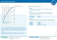
Druck-Flow-Charakteristiken<br />
Nachfolgend sind die Druck-Flow-Charakteristiken der<br />
verfügbaren Druckstufen des <strong>paediGAV</strong> dargestellt.<br />
Druck ( cmH2O)<br />
Druck ( cmH2O)<br />
Druck ( cmH2O)<br />
12<br />
40<br />
35<br />
30<br />
25<br />
20<br />
15<br />
10<br />
5<br />
40<br />
35<br />
30<br />
25<br />
20<br />
15<br />
10<br />
5<br />
40<br />
35<br />
30<br />
25<br />
20<br />
15<br />
10<br />
5<br />
0<br />
0<br />
0<br />
<strong>paediGAV</strong> 4/14 cmH2O<br />
Druckstufe 14 cmH 2O<br />
Druckstufe 4 cmH 2O<br />
5 10 15 20 2530<br />
35 40 45 50 55<br />
Flussrate (ml/h)<br />
<strong>paediGAV</strong> 4/19 cmH2O<br />
Druckstufe 19 cmH 2O<br />
Druckstufe 4 cmH 2O<br />
5 10 15 20 2530<br />
35 40 45 50 55<br />
Flussrate (ml/h)<br />
<strong>paediGAV</strong> 4/24 cmH2O<br />
Druckstufe 24 cmH 2O<br />
Druckstufe 4 cmH 2O<br />
5 10 15 20 2530<br />
35 40 45 50 55<br />
Flussrate (ml/h)<br />
Der gesamte Öffnungsdruck bezieht sich auf einen Referenzflow<br />
von 5ml/h. Für Flussraten von 20 ml/h sind<br />
die angegebenen Drücke ca. 1-2 cmH 2O höher.<br />
Druck ( cmH2O)<br />
Druck ( cmH2O)<br />
Druck ( cmH2O)<br />
40<br />
35<br />
30<br />
25<br />
20<br />
15<br />
10<br />
5<br />
40<br />
35<br />
30<br />
25<br />
20<br />
15<br />
10<br />
5<br />
40<br />
35<br />
30<br />
25<br />
20<br />
15<br />
10<br />
5<br />
0<br />
0<br />
0<br />
<strong>paediGAV</strong> 9/19 cmH2O<br />
Druckstufe 19 cmH 2O<br />
Druckstufe 9 cmH 2O<br />
<strong>paediGAV</strong><br />
5 10 15 20 2530<br />
35 40 45 50 55<br />
Flussrate (ml/h)<br />
<strong>paediGAV</strong> 9/24 cmH2O<br />
Druckstufe 24 cmH 2O<br />
Druckstufe 9 cmH 2O<br />
5 10 15 20 2530<br />
35 40 45 50 55<br />
Flussrate (ml/h)<br />
<strong>paediGAV</strong> 9/29 cmH2O<br />
Druckstufe 29 cmH 2O<br />
Druckstufe 9 cmH 2O<br />
5 10 15 20 2530<br />
35 40 45 50 55<br />
Flussrate (ml/h)<br />
Wiederholungsimplantationen<br />
Produkte, die bereits implantiert waren, dürfen weder<br />
bei dem gleichen noch bei bei einem anderen Patienten<br />
erneut implantiert werden, da eine valide Reinigung<br />
ohne Funktionseinbuße nicht gelingen kann.<br />
Vorsichtsmaßnahmen<br />
Nach der Implantation müssen die Patienten sorgfältig<br />
überwacht werden. Hautrötungen und Spannungen im<br />
Bereich des Drainagegewebes können ein Anzeichen<br />
von Infektionen am SHunTSySTem sein.<br />
Symptome wie Kopfschmerzen, Schwindelanfälle, geistige<br />
Verwirrtheit oder Erbrechen treten häufig bei einer<br />
Shuntdysfunktion auf. Diese Anzeichen wie auch eine<br />
Leckage am SHunTSySTem erfordern den sofortigen<br />
Austausch der Shuntkomponente oder auch des gesamten<br />
SHunTSySTemS.<br />
Verträglichkeit mit diagnostischen Verfahren<br />
Kernspinresonanzuntersuchungen bis zu einer Feldstärke<br />
von 3 Tesla oder computertomographische<br />
Untersuchungen können ohne Gefährdung oder Beeinträchtigung<br />
der Ventilfunktion durchgeführt werden.<br />
Das Ventil ist MR sicher. Die mitgelieferten Katheter<br />
sind MR kompatibel, Reservoire, Umlenker oder Konnektoren<br />
sind MR sicher.<br />
Postoperative Ventilprüfung<br />
Das <strong>paediGAV</strong> ist als funktionssichere Einheit ohne<br />
Pump- oder Prüfeinrichtung konstruiert worden. Es bestehen<br />
aber Möglichkeiten zum Testen bei Verwendung<br />
von SHunTSySTemen mit einer Vorkammer oder<br />
einem Bohrlochreservoir. Die Ventilprüfung kann dann<br />
durch Spülen, Druckmessen oder Pumpen erfolgen.<br />
Funktionssicherheit<br />
Die Ventile sind konstruiert worden, um über lange<br />
Zeiträume präzise und zuverlässig zu arbeiten. Es kann<br />
jedoch keine Garantie dafür übernommen werden,<br />
dass das Ventilsystem nicht aus technischen oder medizinischen<br />
Gründen ausgetauscht werden muss.<br />
Das Ventil und das Ventilsystem halten den während<br />
und nach der Operation auftretenden negativen und<br />
positiven Drücken bis zu 200 cmH2O sicher stand.<br />
Sterilisation<br />
Die Produkte werden unter strenger Kontrolle mit<br />
Dampf sterilisiert. Durch die Doppel-Verpackung in<br />
Steriltüten ist eine fünfjährige Sterilität gewährleistet.<br />
Das jeweilige Verfallsdatum ist auf der Verpackung<br />
angegeben. Bei Beschädigung der Verpackung dürfen<br />
die Produkte auf keinen Fall verwendet werden.<br />
Erneute Sterilisation<br />
Für die Funktionssicherheit von resterilisierten Produkten<br />
kann keine Garantie übernommen werden.<br />
Gebrauchsanweisung<br />
Medizinprodukteberater<br />
Die <strong>Christoph</strong> <strong>Miethke</strong> <strong>GmbH</strong> & <strong>Co</strong>. <strong>KG</strong> benennt entsprechend<br />
den Forderungen der Medizinprodukterichtlinie<br />
93/42/EEC vom 14.06.1993 Medizinprodukteberater,<br />
die Ansprechpartner für alle produktrelevanten<br />
Fragen sind:<br />
Dipl.-Ing. <strong>Christoph</strong> <strong>Miethke</strong><br />
Dipl.-Ing. Roland Schulz<br />
<strong>Christoph</strong> <strong>Miethke</strong> <strong>GmbH</strong> & <strong>Co</strong>. <strong>KG</strong><br />
Ulanenweg 2<br />
14469 Potsdam · Germany<br />
Tel: +49(0) 7000 MIETHKE oder<br />
Tel: +49(0) 331 620 83 0<br />
Fax: +49(0) 331 620 83 40<br />
e-mail: info@miethke.com<br />
Bei Rückfragen wenden Sie sich bitte an:<br />
AESCULAP AG<br />
Am Aesculap-Platz<br />
Tel: +49 (0) 7461 95 0<br />
Fax: +49 (0) 7461 95 26 00<br />
e-mail: information@aesculap.de<br />
Forderungen der Medizinprodukterichtlinie RL<br />
93/42/EEC<br />
Die Medizinprodukterichtlinie fordert die umfassende<br />
Dokumentation des Verbleibs von medizinischen Produkten,<br />
die am Menschen zur Anwendung kommen,<br />
insbesondere für Implantate. Die individuelle Kenn-<br />
Nummer des implantierten Ventils sollte aus diesem<br />
Grunde in der Krankenakte des Patienten vermerkt<br />
werden, um eine lückenlose Rückverfolgbarkeit zu gewährleisten.<br />
Kommentar zur Gebrauchsanweisung<br />
Die hier ausgeführten Beschreibungen basieren auf<br />
den bisher vorliegenden klinischen Erfahrungen. Es<br />
liegt in der Hand des Chirurgen, entsprechend seiner<br />
Erfahrung und der chirurgischen Praxis auf eigene Verantwortung<br />
das OP-Prozedere zu ändern.<br />
Allgemeine Informationen<br />
Hersteller <strong>Christoph</strong> <strong>Miethke</strong><br />
<strong>GmbH</strong> & <strong>Co</strong>. <strong>KG</strong><br />
Produktbezeichnung <strong>paediGAV</strong><br />
Verwendungszweck Behandlung des Hydrocephalus<br />
Zum einmaligen Gebrauch bestimmt<br />
Trocken und sauber lagern<br />
Skizze des Ventils mit äußeren<br />
Abmaßen:<br />
24 mm<br />
4 mm<br />
13
Gebrauchsanweisung<br />
Varianten<br />
Das <strong>paediGAV</strong> ist als Einzelventil oder als SHunTSySTem mit unterschiedlichen<br />
Komponenten erhältlich.<br />
<strong>paediGAV</strong><br />
<strong>paediGAV</strong>-SHUNTSYSTEM (ohne Reservoir)<br />
<strong>paediGAV</strong>-SHUNTSYSTEM mit Bohrlochreservoir<br />
<strong>paediGAV</strong>-SHUNTSYSTEM mit Vorkammer<br />
Maßstab der Grafiken 1:1<br />
14<br />
<strong>Co</strong>ntent<br />
Indication<br />
Technical description<br />
Function of the <strong>paediGAV</strong><br />
Physics background<br />
Selecting the appropriate <strong>paediGAV</strong><br />
Possible shunt components<br />
Tube systems<br />
Surgical procedure<br />
Testing the valve patency<br />
Valve test prior to implantation<br />
Test on reflow safety<br />
Re-implantations<br />
Safety measures<br />
Pressure-flow-characteristics<br />
<strong>Co</strong>mpatibility with diagnostic procedures<br />
Postoperative valve tests<br />
Functional Safety<br />
Sterilisation<br />
Resterilisation<br />
Requirements of the MDD 93/42/EEC<br />
Note on the instructions for use<br />
Medical products consultant<br />
General information<br />
Variants<br />
Instructions for use<br />
16<br />
16<br />
17<br />
18<br />
19<br />
20<br />
20<br />
21<br />
22<br />
22<br />
23<br />
23<br />
23<br />
24<br />
25<br />
25<br />
25<br />
25<br />
25<br />
25<br />
25<br />
25<br />
25<br />
26<br />
15
Instructions for use<br />
CAUTION<br />
Federal law restricts this device to<br />
sale by or on order of a physician!<br />
Indication<br />
The <strong>paediGAV</strong> is intended for use in cases<br />
of pediatric hydrocephalus for the drainage<br />
of cerebrospinal fluid from the ventricles<br />
into the peritoneum.<br />
Technical description<br />
The <strong>paediGAV</strong> is a site-specific shunt<br />
valve for the treatment of pediatric hydrocephalus.<br />
It consists of a ball-cone valve<br />
and a gravity valve. This configuration ensures<br />
physiological drainage in all body<br />
positions.<br />
16<br />
Gravity valve<br />
Ball-cone valve<br />
The <strong>paediGAV</strong> is composed of a robust<br />
titanium casing whose proximal end contains<br />
a ball- cone valve. A spiral spring<br />
(2) controls the opening pressure of the<br />
ball-cone valve. The gravity valve at the<br />
distal end consists of a tantalum ball (3)<br />
that controls the opening pressure of the<br />
gravity valve and a sapphire ball (1) that<br />
ensures reliable sealing and seating of the<br />
gravity valve. As an option, a connector or<br />
a silicone catheter is installed at the distal<br />
end of the valve.<br />
1 sapphire ball<br />
2 spiral spring<br />
3 tantalum ball<br />
Fig. 1 Schematic cross-section<br />
of the <strong>paediGAV</strong><br />
1<br />
2<br />
3<br />
Function of the <strong>paediGAV</strong><br />
The principal operating modes of the<br />
<strong>paediGAV</strong> are shown in Fig. 2 and 3.<br />
Fig. 2a shows the <strong>paediGAV</strong> in horizontal<br />
position. The ball-cone unit is closed (Fig.<br />
2a), thereby preventing any drainage from<br />
taking place. Fig. 2b shows the <strong>paediGAV</strong><br />
in open position. The patient‘s intraventricular<br />
pressure is elevated, and the spring<br />
pressure that would ordinarily keep the<br />
ball-cone valve closed is suppressed.<br />
The sealing ball moves away from the<br />
cone, thereby creating a gap that allows<br />
fluid drainage to occur. When the patient<br />
is in a horizontal position, the gravity valve<br />
remains open and exerts no countervailing<br />
force.<br />
a)<br />
b)<br />
Fig. 2 <strong>paediGAV</strong> in horizontal body<br />
position<br />
Instructions for use<br />
As soon as the patient stands up, the<br />
gravity valve closes and fluid drainage is<br />
interrupted (Fig. 3a). Fluid drainage can<br />
resume only if the sum total of intraventricular<br />
pressure and hydrostatic pressure<br />
exceeds the opening pressure of the ballcone<br />
valve and the force exerted by the<br />
weight of the tantalum ball in the gravity<br />
valve (Fig. 3b).<br />
a) b)<br />
Fig. 3 <strong>paediGAV</strong> in vertical body position<br />
17
Instructions for use<br />
Physics background<br />
With the body in a horizontal position, the<br />
intraventricular pressure in healthy individuals<br />
is positive. To regulate intraventricular<br />
pressure using valve drainage, only the<br />
pressure in the abdominal cavity needs to<br />
be taken into account. In standing position,<br />
the ventricular pressure should be<br />
slightly negative. To regulate ventricular<br />
pressure using shunt valve drainage, valve<br />
opening pressure in standing position<br />
must be set considerably higher.<br />
IVP Intraventricular pressure<br />
PVli Opening pressure in horizontal position<br />
(ball-cone valve only)<br />
PVst Opening pressure in vertical position<br />
(ball-cone valve + gravitational valve)<br />
PB Pressure in the abdominal cavity<br />
PHyd Hydrostatic pressure<br />
18<br />
IVP<br />
PVli<br />
PB<br />
Only in this way can the shunt valve compensate<br />
for the hydrostatic pressure reduced<br />
by the pressure in the abdominal<br />
cavity. <strong>Co</strong>nventional valves open instantly,<br />
as soon as the patient rises to a standing<br />
position, and a critical overdrainage<br />
may occur.<br />
horizontal: IVP = PVli + PB<br />
standing: IVP = PHyd - PVst - PB<br />
PHyd<br />
Fig. 4: Calculation of intraventricular pressure for the horizontal and standing<br />
body positions<br />
IVP<br />
PVst<br />
PB<br />
Selecting the appropriate <strong>paediGAV</strong><br />
The <strong>paediGAV</strong> is a site-dependent valve. It<br />
features two different opening pressures,<br />
one is suitable for the patient‘s horizontal<br />
body position, while the other is used<br />
for the vertical position. This obviates the<br />
necessity of performing percutaneous<br />
modification of valve opening pressure<br />
as much as increased opening pressure<br />
in vertical body position counteracts an<br />
unfavorably high level of drainage. In horizontal<br />
position, on the other hand, the<br />
requisite low opening pressure prevents<br />
underdrainage.<br />
Instructions for use<br />
Horizontal body position:<br />
For the horizontal position, two different<br />
opening pressure settings are available<br />
(4 and 9 cmH2O). Selection of the appropriate<br />
pressure rating should be made in<br />
accordance with indication (age of the<br />
patient).<br />
Vertical body position:<br />
The opening pressure for the vertical<br />
body position depends upon the size of<br />
the patient (hydrostatic parameter). If an<br />
infant is being treated, a low pressure rating<br />
should be selected. If, on the other<br />
hand, a larger child is being treated, a<br />
<strong>paediGAV</strong> with a higher pressure rating<br />
should be applied.<br />
Every <strong>paediGAV</strong> is calibrated according to strict quality control standards. The following<br />
pressure combinations are available:<br />
Opening pressure<br />
(cmH2O)<br />
horizontal vertical<br />
<strong>Co</strong>ding in<br />
X-Ray Image<br />
Standard pressure level<br />
Recommendation<br />
4 24 children up to 6 months<br />
9 24<br />
Children from 6 months<br />
to 5 years<br />
9 29 children over 5 years<br />
4 14<br />
4 19<br />
9 19<br />
Special pressure level<br />
Fig. 5 recommendation of pressure levels (see www.miethke.com)<br />
Radiograph of<br />
a <strong>paediGAV</strong><br />
(9/24 cmH2O)<br />
19
Instructions for use<br />
Possible shunt components<br />
The <strong>paediGAV</strong> is available with different<br />
shunt accessories. These variants consist<br />
of a variety of components, which are<br />
described briefly introduced below:<br />
The borehole reservoir is positioned in the<br />
cranial borehole. It allows measuring the<br />
intraventricular pressure, injecting drugs<br />
and extracting CSF. Its solid titanium base<br />
is highly puncture-resistant. All reservoirs<br />
are available with integrated catheters or<br />
connectors. A special borehole reservoir<br />
is the SprunG reSerVoir. As additional<br />
new feature of this reservoir CSF can<br />
be flushed towards the valve because of a<br />
one-way valve in the bottom of the reservoir.<br />
By this mechanism a flow in the direction<br />
of the ventricular catheter is avoided<br />
during the pumping procedure. The<br />
opening pressure of the SHunTSySTem<br />
is not increased by the implantation of the<br />
SprunG reSerVoir.<br />
The prechamber is positioned on the<br />
craniu m. It allows measuring the intraventricular<br />
pressure, injecting drugs, extracting<br />
CSF and performing a palpatory<br />
ventricle inspection. Its solid titanium<br />
base is highly puncture-resistant. A puncture<br />
of the prechamber or the <strong>Co</strong>nTrol<br />
reSerVoir should be performed as<br />
perpendicular to the reservoir surface as<br />
possible with a cannula of max. 0,9 mm.<br />
30 times of punctures are able without<br />
any restrictions. A special prechamber is<br />
the <strong>Co</strong>nTrol reSerVoir. As an additional<br />
new feature of this reservoir, CSF<br />
can be flushed towards the valve because<br />
of a one-way valve in the proximal inlet of<br />
the reservoir. By this mechanism a flow in<br />
the direction of the ventricular catheter is<br />
avoided during the pumping procedure.<br />
The opening pressure of the SHunTSy-<br />
STem is not increased by the implantation<br />
of the <strong>Co</strong>nTrol reSerVoir.<br />
Warning note: Frequent pumping can<br />
lead to overdrainage and thus to unphysiological<br />
pressure conditions.<br />
The patient should be informed about<br />
the risk.<br />
20<br />
Due to its tight fit on the ventricular catheter,<br />
the deflector allows choosing the<br />
length of catheter penetrating into the<br />
skull prior to implantation. The ventricular<br />
catheter is deflected at a right angle in the<br />
borehole (see chapter “Variants” ).<br />
Tube systems<br />
The <strong>paediGAV</strong> has been designed to ensure<br />
the optimal ventricular pressure. It is<br />
available as a SHunTSySTem or as individual<br />
valve units with or without an integrated<br />
distal catheter (internal diameter<br />
1.2 mm, external diameter 2.5 mm). Individual<br />
valve units should be used with catheters<br />
of approx. 1.2 mm internal diameter<br />
and approx. 2.5 mm external diameter.<br />
The connector on the valve allows using<br />
catheters of 1.0 mm to 1.5 mm internal<br />
diameter. The external diameter of the catheter<br />
should be about double the internal<br />
diameter. In any case, the catheters must<br />
be carefully fixed, with a ligature, to the<br />
valve connectors. Kinks in the catheter<br />
have to be avoided.<br />
The provided catheters have virtually no<br />
effect on the Pressure-flow characteristics.<br />
Surgical procedure<br />
positioning the ventricular catheter<br />
A number of different operative techniques<br />
can be used to position the ventricular<br />
catheter:<br />
Preferably, the required skin incision<br />
should be carried out either in form of a<br />
skin lobule pedicled towards the draining<br />
catheter or as a straight skin incision. In<br />
order to prevent cerebrospinal fluid from<br />
leaking, it should be taken care that the<br />
opening of the dura is as small as possible<br />
after drilling the borehole. The ventricular<br />
catheter is stiffened by the mandrin supplied<br />
with the product.<br />
The <strong>paediGAV</strong> is available in various shunt<br />
configurations.<br />
When the <strong>paediGAV</strong>-SHunTSySTem is<br />
used with a borehole reservoir, the ventricular<br />
catheter is implanted first. Then<br />
the mandrin is removed and the patency<br />
of the valve can be checked by letting<br />
CSF drip out. The catheter is shortened<br />
and the borehole reservoir is connected,<br />
securing the connection with a ligature.<br />
The skin incision should not be situated<br />
directly above the reservoir.<br />
When a <strong>paediGAV</strong>-SHunTSySTem with<br />
a prechamber is used, an included borehole<br />
deflector is used to adjust the catheter<br />
that is to be implanted to the required<br />
length. The ventricular catheter is inserted<br />
in the ventricle and placed at a 90 degree<br />
angle, and the prechamber is then set in<br />
place.<br />
The position of the ventricular catheter<br />
should be verified postoperatively by means<br />
of CT or MRI.<br />
Instructions for use<br />
positioning the <strong>paediGAV</strong><br />
The <strong>paediGAV</strong> is a site-dependent valve.<br />
<strong>Co</strong>nsequently, care must be taken to<br />
ensure that the shunt valve is implanted<br />
parallel to the body axis. A suitable implant<br />
site is behind the ear. After the skin<br />
incision and subcutaneous tunneling have<br />
been performed, the catheter is pushed<br />
from the borehole or reservoir to the selected<br />
shunt valve implantation site. The<br />
catheter is shortened (if necessary), and<br />
is then attached to the <strong>paediGAV</strong> with a<br />
ligature. In doing this, care must be taken<br />
to ensure that the shunt valve is not localized<br />
directly beneath the skin incision.<br />
The shunt valve is equipped with an arrow<br />
pointing distally and downwards, indicating<br />
flow direction.<br />
positioning the peritoneal catheter<br />
The access site for the peritoneal catheter<br />
is left to the surgeon’s discretion. For<br />
example, it can be created as a horizontal<br />
access, paraumbilical or transrectal,<br />
adjacent to the epigastrium.<br />
<strong>Co</strong>ncerning the operative technique for<br />
positioning of the peritoneal catheter,<br />
there are various options, too.<br />
The peritoneal catheter should be guided<br />
from the shunt valve to the selected<br />
position with the aid of a subcutaneous<br />
tunneler, and if necessary, an auxiliary<br />
incision. The peritoneal catheter – which<br />
as a rule is fastened to the <strong>paediGAV</strong> –<br />
is equipped with an open distal end, but<br />
has no wall aperture. Having exposed and<br />
entered the peritoneum, or by means of a<br />
trocar, the peritoneal catheter (shortened<br />
if necessary) is pushed forward into the<br />
intestinal cavity.<br />
21
Instructions for use<br />
Testing the valve patency<br />
22<br />
isotonic sterile sodium chloride solution<br />
Fig. 6: patency test Fig. 7: Test setup<br />
The <strong>paediGAV</strong> can be filled most gently by aspiration<br />
through a sterile, single-use syringe attached to the distal<br />
end of the catheter. The proximal end of the valve<br />
is immersed in a sterile, physiological saline solution.<br />
The valve is patent if fluid can be extracted in this way<br />
(see Fig. 6).<br />
Caution: Pressure admission through the singleuse<br />
syringe should be avoided, both at the proximal<br />
and the distal end. <strong>Co</strong>ntaminations in the solution<br />
used for the test can impair the product’s<br />
performance.<br />
Valve test prior to implantation<br />
Each <strong>paediGAV</strong> valve has been tested to ensure that<br />
the performance specifications given on the label are<br />
always met. The dynamic performance characteristics<br />
of the shunt cannot be tested in a static test performed<br />
in the operating room.<br />
If the surgeon wishes to verify, prior to implantation,<br />
that the shunt meets the specifications given by the<br />
manufacturer, the test described in the following can<br />
be carried out in the operating room:<br />
Caution: Always take care that sterility is<br />
maintained and particle contamination is avoided.<br />
Test method<br />
Equipment required for this test:<br />
a) sterile fluid reservoir or water bath<br />
b) sterile fluid 60-cm water manometer with millimeter<br />
grading and three-branch faucet at the base<br />
c) sterile syringe, 30 cc to 50 cc<br />
d) sterile 5-µ tip filter<br />
e) sterile tube adapter<br />
f) sterile silicone tube<br />
Setting up the equipment<br />
a) Position the manometer and the water bath in such<br />
a way that the zero point of the manometer and the fluid<br />
level of the water bath are at the same height (see<br />
Fig. 7).<br />
b) Fill the syringe, with the 5-µ tip filter attached, with<br />
sterile water (Always use the 5-µ tip filter when topping<br />
up the syringe.). Remove the tip filter when the syringe<br />
is full.<br />
c) <strong>Co</strong>nnect the syringe, the manometer and the silicone<br />
tube with each other. Use the tube adapter if necessary.<br />
(see Fig. 7)<br />
d) To release all air from the test assembly, turn the<br />
three-way faucet as shown in Fig. 8.<br />
e) Immerse the silicone tube in the sterile water bath<br />
and rinse it with the sterile water from the syringe.<br />
3<br />
2<br />
1 <strong>paediGAV</strong> a horizontal, b vertical; 2 water bath;<br />
3 constant water level; 4 silicone tube; 5 three-way tap;<br />
6 single-use syringe with syringe filter; 7 manometer<br />
Calibrating the equipment<br />
a) Turn the three-way faucet as shown in Fig. 9 and fill<br />
the manometer to at least 5 cmH2O.<br />
b) With the silicone tube immersed in the water bath,<br />
turn the three-way faucet so that the syringe is isolated<br />
from the manometer (see Fig. 10).<br />
c) Allow the water column in the manometer to drop.<br />
d) The water column should stop dropping at the zero<br />
point. Adjust the zero point of the manometer to fluid<br />
level of the water bath, if necessary.<br />
e) The manometer has now been calibrated to the<br />
zero-level of the water bath. Fixate the manometer to<br />
maintain its position in relation to the water bath.<br />
to valve<br />
Fig. 8<br />
1b<br />
closed<br />
to valve<br />
Fig. 9<br />
open<br />
to valve<br />
Fig. 10<br />
4<br />
1a<br />
5<br />
closed<br />
0<br />
60 cm<br />
7<br />
from syringe<br />
open<br />
from syringe<br />
from syringe<br />
closed<br />
4<br />
6<br />
Test procedure<br />
Please note: During the test the shunt must be<br />
submerged in the water bath. The zero point of<br />
the manometer has to be aligned with the water<br />
level of the water bath in order to obtain correct<br />
results.<br />
a) <strong>Co</strong>nnect the sterile shunt to be tested to the ready<br />
assembled, sterile test equipment.<br />
b) Turn the three-way faucet as shown in Fig. 9 and fill<br />
the manometer to 10 cmH2O above the expected opening<br />
pressure. (Example: For testing a <strong>paediGAV</strong> with<br />
an opening pressure setting of 5 cmH2O horizontal and<br />
25 cmH2O vertical, the manometer is filled to 15 cm-<br />
H2O with the shunt in a horizontal position and to 40<br />
cmH2O with the shunt in a vertical position.)<br />
c) Turn the three-way faucet as shown in Fig. 8 so that<br />
the manometer is isolated.<br />
d) Remove all air from the shunt and the test setup by<br />
carefully rinsing it through with sterile water from the<br />
syringe.<br />
e) Immerse the sterile shunt in the sterile water bath.<br />
The distal part of the shunt must be under water to obtain<br />
valid test results.<br />
f) Carefully maintain a flow through the shunt and turn<br />
the three-way faucet as shown in Fig. 10 to isolate the<br />
syringe. As soon as the three-way faucet is in the correct<br />
position, the water column should begin to drop.<br />
The syringe is now isolated from the valve and it is not<br />
necessary anymore to maintain its flow. Repeat steps b<br />
to f if the water column fails to drop.<br />
g) Allow the water level in the manometer to drop for<br />
2 to 2.5 minutes. Read the resulting pressure at the<br />
manometer.<br />
Test results of preimplantation test<br />
The pressure readings obtained by this method should<br />
yield the following results:<br />
Opening pressure<br />
cmH2O<br />
horizontal valve position<br />
Acceptable pressure<br />
range<br />
4 cmH2O 1-6 cmH2O<br />
9 cmH2O 4-12 cmH2O<br />
Opening pressure<br />
cmH2O<br />
vertical valve position<br />
Acceptable pressure<br />
range<br />
14 cmH2O 5-14 cmH2O<br />
19 cmH2O 9-19 cmH2O<br />
24 cmH2O 12-24 cmH2O<br />
29 cmH2O 15-29 cmH2O<br />
Instructions for use<br />
Test on reflow safety<br />
This test is carried out with the same equipment as<br />
the preimplantation test. The shunt is carefully filled<br />
with sterile saline solution from the syringe before the<br />
air is removed from it (Fig. 11). The shunt is connected<br />
against the direction of flow (see arrow on the shunt).<br />
The outlet of the shunt has to be at the zero level of the<br />
manometer. The manometer is filled up to 14 cmH2O<br />
(Fig. 12).<br />
The three-way faucet is used for unblocking the flow to<br />
the shunt and blocking the flow to syringe. In this setup,<br />
no more than 2 drops (0.1 cc) per minute should emerge<br />
from the proximal part of the shunt (Fig. 13).<br />
Fig. 11<br />
Fig. 12<br />
Fig. 13<br />
isotonic sterile sodium<br />
chloride solution<br />
0-level<br />
0-level<br />
closed<br />
open<br />
14 cm<br />
open<br />
14 cm<br />
closed<br />
Caution: Be careful to maintain sterility and to<br />
avoid particle contamination.<br />
Reimplantation<br />
Under no circumstances should products that have<br />
had previously been implanted in a patient be subsequently<br />
reimplanted in another, as a validated decontamination<br />
process will compromise the functionality<br />
of the valve.<br />
Safety measures<br />
The patients must be carefully monitored after the<br />
implantation. Reddened skin and tension in the area<br />
of the drainage tissue could indicate infections at the<br />
SHunTSySTem. Symptoms such as headache, dizzy<br />
spells, mental confusion or vomiting are common occurrences<br />
in cases of shunt dysfunction. Such symptoms,<br />
as well as shunt system leakage, necessitate<br />
the immediate replacement of the shunt component<br />
responsible, or of the entire SHunTSySTem.<br />
23
Instructions for use<br />
Pressure-flow characteristics<br />
The pressure flow characteristics of the pressure ratings<br />
available for the <strong>paediGAV</strong> are shown in the following<br />
graphs:<br />
pressure ( cmH2O)<br />
pressure ( cmH2O)<br />
pressure ( cmH2O)<br />
24<br />
40<br />
35<br />
30<br />
25<br />
20<br />
15<br />
10<br />
5<br />
40<br />
35<br />
30<br />
25<br />
20<br />
15<br />
10<br />
5<br />
40<br />
35<br />
30<br />
25<br />
20<br />
15<br />
10<br />
5<br />
0<br />
0<br />
0<br />
<strong>paediGAV</strong> 4/14 cmH2O<br />
pressure rating 14 cmH 2O<br />
pressure rating 4 cmH 2O<br />
5 10 15 20 2530<br />
35 40 45 50 55<br />
flow (ml/h)<br />
<strong>paediGAV</strong> 4/19 cmH2O<br />
pressure rating 19 cmH 2O<br />
pressure rating 4 cmH 2O<br />
5 10 15 20 2530<br />
35 40 45 50 55<br />
flow (ml/h)<br />
<strong>paediGAV</strong> 4/24 cmH2O<br />
pressure rating 24 cmH 2O<br />
pressure rating 4 cmH 2O<br />
5 10 15 20 2530<br />
35 40 45 50 55<br />
flow (ml/h)<br />
The total opening pressure refers to a reference flow of<br />
5 ml/h. When the flowrates reach 20 ml/h, the opening<br />
pressures are approximately 1-2 cmH 2O higher.<br />
pressure ( cmH2O)<br />
pressure ( cmH2O)<br />
pressure ( cmH2O)<br />
40<br />
35<br />
30<br />
25<br />
20<br />
15<br />
10<br />
5<br />
40<br />
35<br />
30<br />
25<br />
20<br />
15<br />
10<br />
5<br />
40<br />
35<br />
30<br />
25<br />
20<br />
15<br />
10<br />
5<br />
0<br />
0<br />
0<br />
<strong>paediGAV</strong> 9/19 cmH2O<br />
pressure rating 19 cmH 2O<br />
pressure rating 9 cmH 2O<br />
5 10 15 20 2530<br />
35 40 45 50 55<br />
flow (ml/h)<br />
<strong>paediGAV</strong> 9/24 cmH2O<br />
pressure rating 24 cmH 2O<br />
pressure rating 9 cmH 2O<br />
5 10 15 20 2530<br />
35 40 45 50 55<br />
flow (ml/h)<br />
<strong>paediGAV</strong> 9/29 cmH2O<br />
pressure rating 29 cmH 2O<br />
pressure rating 9 cmH 2O<br />
5 10 15 20 2530<br />
35 40 45 50 55<br />
flow (ml/h)<br />
<strong>Co</strong>mpatibility with diagnostic procedures<br />
MRI examinations with field strengths of up to 3.0 tesla<br />
and CT examinations can be carried without endangering<br />
or impairing the functionality of the shunt.<br />
The <strong>paediGAV</strong> is MR conditional (ASTM-F2503-08). All<br />
components are visible via X-ray. The provided catheters<br />
are MRI safe. Reservoirs, deflectors and connectors<br />
are MR conditional.<br />
Postoperative valve test<br />
The <strong>paediGAV</strong> has been designed as a safe and reliable<br />
unit even without the provision of a pumping device.<br />
However, there are ways of testing the unit if a SHunT-<br />
SySTem with a prechamber or a borehole reservoir is<br />
used. Valve tests can be carried out by flushing or pressure<br />
measurements.<br />
Functional safety<br />
The valves have been designed for long-term reliable<br />
and precise operation. Still, the possibility that the<br />
shunt system needs to be replaced for technical or medical<br />
reasons, cannot be excluded.The valve and the<br />
valve system are able to resist positive and negative<br />
pressure up to 200 cmH 2 O during and after implantation.<br />
Warning note for carriers of pacemakers: Due to<br />
the implantation of a <strong>paediGAV</strong> the function of a<br />
pacemaker can be affected.<br />
Sterilisation<br />
The products are sterilized with steam under closely<br />
monitored conditions. The double wrapping in sterile<br />
bags ensures sterility for a period of five years. The expiry<br />
date is printed on the wrapping of each individual<br />
product. Products taken from a damaged wrapping<br />
must not be used under any circumstances.<br />
Resterilisation<br />
The functional safety and reliability of resterilized products<br />
cannot be guaranteed, therefore resterilisation is<br />
not recommended.<br />
Requirements of the MDD 93/42/EEC<br />
The MDD calls for the comprehensive documentation<br />
of the whereabouts of medical products that are applied<br />
in human beings, especially the whereabouts of<br />
implants. For this reason, the individual identification<br />
numbers of any implanted valves are to be noted in<br />
patients‘ records, so that in the event of any inquiries,<br />
the implant can be traced without any difficulties. Each<br />
valve is outfitted with a sticker for this purpose.<br />
Note on the instructions for use<br />
The descriptions and explanations given in this document<br />
are based on the clinical experience available to<br />
date. It is for the surgeon to decide if surgical procedures<br />
should be changed according to his or her experience<br />
and to surgical practice.<br />
Instructions for use<br />
Medical products consultant<br />
In compliance with the requirements of the European<br />
law MDD 93/42/EEC, <strong>Christoph</strong> <strong>Miethke</strong> <strong>GmbH</strong> & <strong>Co</strong>.<br />
<strong>KG</strong> names medical pro duct consultants as the individuals<br />
to be addressed with all queries concerning the<br />
products:<br />
Dipl.-Ing. <strong>Christoph</strong> <strong>Miethke</strong><br />
Dipl.-Ing. Roland Schulz<br />
<strong>Christoph</strong> <strong>Miethke</strong> <strong>GmbH</strong> & <strong>Co</strong>. <strong>KG</strong><br />
Ulanenweg 2<br />
14469 Potsdam · Germany<br />
Phone: +49(0) 7000 MIETHKE or<br />
Phone: +49(0) 331 620 83 0<br />
Fax: +49(0) 331 620 83 40<br />
e-mail: info@miethke.com<br />
Please address any enquiries to:<br />
AESCULAP AG<br />
Am Aesculap-Platz<br />
78532 Tuttlingen · Germany<br />
Phone: +49 (0) 7461 95 0<br />
Fax: +49 (0) 7461 95 26 00<br />
e-mail: information@aesculap.de<br />
Service address in the US<br />
AESCULAP Inc.<br />
Attn. AESCULAP Technical Services<br />
615 Lambert Pointe Road<br />
Hazelwood, MO, 63042<br />
AESCULAP Repair Hotline<br />
Phone: +1 (800) 214-3392<br />
Fax: +1 (314) 895-4420<br />
Distributor in the US/ <strong>Co</strong>ntact in Canada<br />
AESCULAP Inc.<br />
3773 <strong>Co</strong>rporate Parkway<br />
Center Valley, PA 18034<br />
Phone: +1-800-282-9000<br />
www.aesculapusa.com<br />
General information<br />
Manufacturer <strong>Christoph</strong> <strong>Miethke</strong><br />
<strong>GmbH</strong> & <strong>Co</strong>. <strong>KG</strong><br />
Product name <strong>paediGAV</strong><br />
Intended use Treatment of Hydrocephalus<br />
Intended for one-time use (disposable)<br />
Store in a clean, dry place<br />
Schematic representation of the shunt with its<br />
external dimensions:<br />
24 mm<br />
4 mm<br />
25
Instructions for use<br />
Variants<br />
The <strong>paediGAV</strong> is available as a single valve or as a SHunTSySTem comprising<br />
various components.<br />
<strong>paediGAV</strong><br />
<strong>paediGAV</strong>-SHUNTSYSTEM<br />
<strong>paediGAV</strong>-SHUNTSYSTEM with borehole reservoir<br />
<strong>paediGAV</strong>-SHUNTSYSTEM with prechamber<br />
Scale 1:1<br />
26<br />
Sommaire<br />
Indication<br />
Description technique<br />
Fonctionnement de la <strong>paediGAV</strong><br />
Données physiques<br />
Choix de la valve <strong>paediGAV</strong> appropriée<br />
<strong>Co</strong>mposants de shunt possibles<br />
Systèmes de cathéters<br />
Déroulement de l’opération<br />
<strong>Co</strong>ntrôle de la perméabilité de la valve<br />
Test de la valve avant l’implantation<br />
Test sur la sécurité de reflux<br />
Caractéristique pression-débit<br />
Nouvelles Implantations<br />
Mesures de précaution<br />
<strong>Co</strong>mpatibilité avec les procédés diagnostiques<br />
<strong>Co</strong>ntrôle postopératoire de la valve<br />
Sécurité du fonctionnement<br />
Stérilisation<br />
Nouvelle stérilisation<br />
Obligations imposées par la loi MDD 93/42/EEC<br />
Remarque sur le mode d’emploi<br />
<strong>Co</strong>nseillers en produits médicaux<br />
Informations générales<br />
Variantes<br />
Mode d´emploi<br />
28<br />
28<br />
29<br />
30<br />
31<br />
32<br />
32<br />
33<br />
34<br />
34<br />
35<br />
36<br />
37<br />
37<br />
37<br />
37<br />
37<br />
37<br />
37<br />
37<br />
37<br />
37<br />
37<br />
38<br />
27
Mode d´emploi<br />
Indication<br />
La valve <strong>paediGAV</strong> est utilisée dans les<br />
cas d’hydrocéphalie pédiatrique pour le<br />
drainage du liquide, qui est conduit hors<br />
des ventricules dans le péritoine.<br />
Description technique<br />
La valve <strong>paediGAV</strong> travaille en fonction de<br />
la position, elle est mise en oeuvre dans le<br />
traitement de l’hydrocéphalie pédiatrique.<br />
Elle est composée d’une valve conique à<br />
bille et d’une valve gravitationnelle. Il est<br />
ainsi possible de garantir un drainage<br />
physiologique dans toutes les positions<br />
du corps.<br />
28<br />
Valve gravitationnelle<br />
Valve conique à bille<br />
La valve est composée d’un boîtier robuste<br />
en titane, à l’extrémité proximale<br />
duquel est intégrée une valve conique à<br />
bille de conception éprouvée. Un ressort<br />
spiral (2) assure la pression d’ouverture<br />
de la valve conique à bille. La valve gravitationnelle<br />
dans la zone distale<br />
est constituée de la bille en tantale (3), qui<br />
détermine la pression d’ouverture de cette<br />
valve et de la bille en saphir (1), qui garantit<br />
la fermeture de précision. À l’extrémité<br />
distale de la valve est intégré au choix un<br />
connecteur ou un cathéter en silicone.<br />
1 Bille en saphir<br />
2 ressort spiral<br />
3 Bille en tantale<br />
Fig. 1 <strong>Co</strong>upe schématisée de la valve <strong>paediGAV</strong><br />
1<br />
2<br />
3<br />
Fonctionnement de la <strong>paediGAV</strong><br />
Le principe de fonctionnement de la valve<br />
<strong>paediGAV</strong> est décrit à la Fig. 2 et à la<br />
Fig. 3. La Fig. 2 montre la valve <strong>paediGAV</strong><br />
en position horizontale. La valve conique<br />
à bille est fermée (Fig.2a) et un drainage<br />
s‘avère impossible. A la Fig. 2b, la valve<br />
<strong>paediGAV</strong> est représentée à l’état ouvert.<br />
La PIV de l‘enfant est accrue et la force<br />
de ressort qui maintient fermée la valve<br />
conique à bille est surmontée. La bille<br />
d’obturation se déplace maintenant hors<br />
du cône et libère un interstice pour le drainage<br />
du liquide. La valve gravitationnelle<br />
est toujours ouverte en position couchée<br />
et ne présente pas de résistance.<br />
a)<br />
b)<br />
Fig. 2 <strong>paediGAV</strong> en position horizontale<br />
du corps<br />
Mode d´emploi<br />
Au moment où l’enfant se redresse, la<br />
valve gravitationnelle se ferme et le drainage<br />
du liquide est interrompu (Fig. 3a).<br />
Ce n’est que lorsque la somme de la PIV<br />
et de la pression hydrostatique excède la<br />
pression d’ouverture de la valve conique à<br />
bille et la force opposée par le poids de la<br />
bille en tantale de la valve gravitationnelle,<br />
qu‘un drainage du liquide est à nouveau<br />
possible (Fig. 3b).<br />
a) b)<br />
Fig. 3 <strong>paediGAV</strong> en position verticale du corps<br />
29
Mode d´emploi<br />
Données physiques<br />
En position couchée, la pression intraventriculaire<br />
est positive chez le sujet en<br />
bonne santé. Pour régler cette pression<br />
au moyen d’un drainage à valve, il faut<br />
uniquement tenir compte de la pression de<br />
l‘espace abdominal.<br />
Lorsque le corps est en position verticale,<br />
la pression ventriculaire physiologique<br />
souhaitée devrait être légèrement négative.<br />
IVP Pression intraventriculaire<br />
PVli Pression d’ouverture de la valve en<br />
position couchée (valve conique à bille<br />
seulement)<br />
PVst Pression d’ouverture de la valve en<br />
position debout<br />
(valve conique à bille+ valve gravitationnelle)<br />
PB Pression dans la cavité abdominale<br />
PHyd Pression hydrostatique<br />
30<br />
IVP<br />
PVli<br />
PB<br />
Pour régler cette pression au moyen d’un<br />
drainage à valve, la pression de l‘ouverture<br />
de la valve doit être réglée bien plus haut<br />
dans cette position du corps. Ce n‘est<br />
qu‘ ainsi que la valve peut compenser la<br />
pression hydrostatique dont est déduite<br />
la pression de l’espace abdominal. Les<br />
valves conventionnelles s’ouvrent immédiatement<br />
en position verticale du corps et<br />
peuvent entraîner un surdrainage critique.<br />
<strong>Co</strong>uché: IVP = PVli + PB<br />
Debout: IVP = PHyd - PVst - PB<br />
PHyd<br />
Fig. 4: pressions de la valve pour les positions corporelles horizontales et verticales.<br />
IVP<br />
PVst<br />
PB<br />
Choix de la valve <strong>paediGAV</strong><br />
appropriée<br />
La valve <strong>paediGAV</strong> travaille en fonction<br />
de la position. Elle possède deux pressions<br />
d’ouverture différentes. L’une des<br />
pressions d’ouverture est prévue pour la<br />
position corporelle horizontale du patient,<br />
l’autre pour la position verticale. Il est ainsi<br />
possible d’éviter un réajustement percutané<br />
de la pression d’ouverture de la valve,<br />
puisqu’une pression d’ouverture élevée en<br />
position verticale du corps empêche un<br />
drainage excessivement fort, tandis que<br />
la faible pression d’ouverture nécessaire<br />
en position horizontale exclut un drainage<br />
insuffisant.<br />
Mode d´emploi<br />
position horizontale du corps:<br />
Deux pressions d’ouverture différentes<br />
pour la position corporelle horizontale sont<br />
proposées (4 et 9 cmH 2O). On recommande<br />
de sélectionner dans ce cas un niveau<br />
de pression correspondant à l’indication<br />
(l’âge de l’enfant).<br />
position verticale du corps:<br />
La pression d’ouverture pour la position<br />
verticale du corps dépend de la taille de<br />
l’enfant (hydrostatique). Pour le traitement<br />
du nourrisson, il est conseillé de choisir un<br />
niveau de pression faible; pour un enfant<br />
plus âgé, on pourra choisir une valve<br />
<strong>paediGAV</strong> avec un niveau de pression plus<br />
élevé. (voir „pressure recommendations“<br />
on www.miethke.com)<br />
Chaque valve <strong>paediGAV</strong> est calibrée sous un contrôle de qualité sévère. Les combinaisons<br />
suivantes de niveaux de pression sont disponibles:<br />
Pression d‘ouverture <strong>Co</strong>dage sur<br />
à l’hori- à la le cliché<br />
Recommandation<br />
zontale vertical radiographique<br />
Niveaux de pression standard<br />
4 24 Enfants jusqu‘à 6 mois<br />
9 24<br />
Enfants<br />
de 6 mois à 5 ans<br />
9 29 Enfants de plus de 5 ans<br />
4 14<br />
4 19<br />
9 19<br />
Niveaux de pression spéciales<br />
Fig. 5 recommandation des niveaux de pression (voir www.miethke.com)<br />
Cliché radiographique<br />
de la<br />
valve <strong>paediGAV</strong><br />
(9/24 cmH2O)<br />
31
Mode d´emploi<br />
<strong>Co</strong>mposants de shunt possibles<br />
La <strong>paediGAV</strong> est disponible avec différents<br />
accessoires de shunt. Ces variantes<br />
de shunt possèdent différents composants<br />
qui sont brièvement présentés cidessous.<br />
Le borehole reservoir est placé<br />
dans la perforation de la calotte crânienne<br />
et permet de mesurer la pression intracrânienne,<br />
d’injecter des médicaments et de<br />
prélever du LCR. Le fond robuste en titane<br />
est hautement résistant au percement.<br />
Tous les réservoirs sont disponibles avec<br />
des cathéters ou des connecteurs intégrés.<br />
Le SprunG reSerVoir est un<br />
borehole reservoir spécial. La nouvelle<br />
caractéristique additionnelle de ce réservoir<br />
est la possibilité de pomper le LCR<br />
vers la valve grâce à un clapet anti-retour<br />
intégré dans le fond du reservoir.<br />
Pendant le pompage, l’accès au cathéter<br />
ventriculaire est fermé. La pression<br />
d’ouverture du SHunTSySTem n’est<br />
pas augmentée par la mise en œuvre du<br />
SprunG reSerVoir.<br />
Le prechamber est placé sur la calotte<br />
crânienne. Il permet de mesurer la pression<br />
intraventriculaire, d’injecter des médicaments,<br />
de prélever du liquide céphalorachidien<br />
et d’effectuer un contrôle de la<br />
valve par palpation. Le fond robuste en<br />
titane est hautement résistant au percement.<br />
Le <strong>Co</strong>nTrol reSerVoir est une<br />
préchambre spéciale. La nouvelle caractéristique<br />
additionnelle de ce réservoir est<br />
la possibilité de pomper le LCR vers la<br />
valve grâce à un clapet anti-retour intégré<br />
dans l’arrivée proximale du réservoir.<br />
Pendant le pompage, l’accès au cathéter<br />
ventriculaire est fermé. La pression<br />
d’ouverture du SHunTSySTem n’est<br />
pas augmentée par la mise en œuvre du<br />
<strong>Co</strong>nTrol reSerVoir (voir le chapitre<br />
„variantes“).<br />
Avertissement: Un pompage fréquent<br />
peut entraîner un drainage excessif et<br />
par conséquent des rapports de pression<br />
non physiologiques. Le patient<br />
doit être informé de ce risque.<br />
32<br />
Le deflector, grâce à sa fixation serrée<br />
sur le cathéter ventriculaire, permet de<br />
choisir avant l’implantation la longueur de<br />
cathéter pénétrant dans le crâne. Le cathéter<br />
ventriculaire est dévié l’angle droit<br />
dans la perforation.<br />
Systèmes de cathéters<br />
La <strong>paediGAV</strong> est conçue de façon à garantir<br />
la pression ventriculaire optimale<br />
conformément à l’indication du médecin.<br />
Elle peut être commandée comme<br />
le SHunTSySTem ou comme unité de<br />
valve isolée avec ou sans cathéter distal<br />
intégré (diamètre intérieur 1,2 mm, diamètre<br />
extérieur 2,5 mm). Si l’on n’utilise pas<br />
de SHunTSySTem, il est recommandé<br />
d’utiliser des cathéters avec de diamètre<br />
intérieur d’env. 1,2 mm et de diamètre extérieur<br />
d’env. 2,5 mm. Le connecteur de la<br />
valve permet d’utiliser des cathéters avec<br />
un diamètre intérieur de 1,0 mm à 1,5 mm.<br />
Le diamètre extérieur du cathéter devrait<br />
être le double du diamètre intérieur. Dans<br />
tous les cas, les cathéters doivent être<br />
soigneusement fixés par ligature aux connecteurs<br />
de la valve. Il faut éviter des pliures<br />
des cathéters.<br />
Les cathéters fournis n’ont pratiquement<br />
aucune incidence sur les caractéristiques<br />
de pression et de débit.<br />
Déroulement de l’opération<br />
mise en place du cathéter ventriculaire<br />
Différentes techniques opératoires sont<br />
possibles pour la mise en place du cathéter<br />
ventriculaire. L’incision cutanée nécessaire<br />
doit être effectuée de préférence<br />
sous forme de lambeau avec pédicule<br />
orienté vers le cathéter de dérivation ou,<br />
dans des cas exceptionnels seulement,<br />
sous forme d’incision cutanée rectiligne.<br />
Il faut veiller à ce qu’après la réalisation de<br />
la perforation, l’ouverture de la dure-mère<br />
soit la plus réduite possible pour éviter<br />
une fuite de liquide céphalo-rachidien. Le<br />
cathéter ventriculaire est stabilisé par le<br />
mandrin ci-joint.<br />
La valve <strong>paediGAV</strong> existe en différentes<br />
variantes de shunt:<br />
En cas de recours à un <strong>paediGAV</strong>-<br />
SHunTSySTem avec borehole reservoir<br />
ou SprunG reSerVoir, le cathéter<br />
ventriculaire est implanté en premier lieu.<br />
Après le retrait du mandrin, la perméabilité<br />
du cathéter ventriculaire peut être<br />
contrôlée par l’écoulement de gouttes de<br />
liquide céphalo-rachidien. Le cathéter est<br />
raccourci et le réservoir de perforation<br />
connecté, la connexion étant consolidée<br />
par une ligature. L’incision cutanée ne<br />
devrait pas se situer juste au-dessus du<br />
réservoir.<br />
En cas de recours à un <strong>paediGAV</strong>-SHunT-<br />
SySTem with prechamber or <strong>Co</strong>nTrol<br />
reSerVoir, un deflector est fourni. Ce<br />
deflector permet d’ajuster la longueur de<br />
cathéter à implanter et de le pousser dans<br />
le ventricule. Le cathéter ventriculaire et<br />
dévié, la préchambre est mise en place.<br />
La position du cathéter ventriculaire doit<br />
être contrôlée à nouveau par imagerie<br />
scanner ou IRM.<br />
Mode d´emploi<br />
mise en place de la valve <strong>paediGAV</strong><br />
La valve <strong>paediGAV</strong> travaille en fonction<br />
de la position. Il faut donc veiller à ce que<br />
la valve soit implantée parallèlement à<br />
l‘axe du corps. Le lieu d’implantation approprié<br />
est le placement derrière l’oreille.<br />
L’incision cutanée et la tunnélisation de la<br />
peau une fois effectuées, le cathéter est<br />
introduit à partir de la perforation vers<br />
le lieu d’implantation de la valve. Le cathéter<br />
est raccourci si nécessaire et fixé<br />
à la valve <strong>paediGAV</strong> par ligature, la valve<br />
ne devant pas se trouver directement audessous<br />
de l’incision cutanée. La valve<br />
est pourvue d’une flèche indiquant la direction<br />
du débit (flèche en direction distale,<br />
ou vers le bas).<br />
Un pompage fréquent peut entraîner<br />
un drainage excessif et par conséquent<br />
des rapports de pression non<br />
physiologiques. Le patient doit être<br />
informé de ce risque.<br />
mise en place du cathéter péritonéal<br />
Le lieu d’accès pour le cathéter péritonéal<br />
est laissé au choix du chirurgien. Il peut<br />
p. ex. faire l’objet d’un positionnement horizontal<br />
paraombilical ou transrectal à la<br />
hauteur de l’épigastre.<br />
De même, différentes techniques opératoires<br />
peuvent être utilisées pour la mise<br />
en place du cathéter péritonéal.<br />
On recommande de tirer le cathéter péritonéal<br />
à l‘aide d’un instrument de tunnélisation<br />
sous-cutané à partir de la valve,<br />
éventuellement à l’aide d’une incision annexe,<br />
jusqu’au lieu du positionnement. Le<br />
cathéter péritonéal, en général fermement<br />
fixé à la <strong>paediGAV</strong>, a une extrémité distale<br />
ouverte et pas de rainure dans sa paroi.<br />
Après le dégagement et la pénétration du<br />
péritoine, ou à l’aide d’un trocart, le cathéter<br />
péritonéal raccourci si nécessaire est poussé<br />
dans la cavité abdominale libre.<br />
33
Mode d´emploi<br />
<strong>Co</strong>ntrôle de la perméabilité de la valve<br />
34<br />
Sérum physiologique isotonique<br />
Fig. 6: <strong>Co</strong>ntrôle de perméabilité<br />
Le remplissage de la <strong>paediGAV</strong>, à effectuer avec autant<br />
de précautions que possible, peut avoir lieu par aspiration<br />
à l’aide d’une seringue stérile à usage unique placée<br />
à l’extrémité distale du cathéter. L’extrémité proximale<br />
de la valve est ainsi maintenue dans une solution<br />
stérile de sérum physiologique. La valve est perméable<br />
s’il est possible de prélever du LCR (voir Fig. 6).<br />
Attention : il faut éviter une mise sous pression<br />
au moyen d’une seringue à usage unique tant à<br />
l’extrémité proximale que distale. Des impuretés<br />
dans la solution utilisée pour le test peuvent porter<br />
préjudice à la performance du produit.<br />
Test de la valve avant l’implantation<br />
Les valves <strong>paediGAV</strong> font toutes l‘objet d‘un test servant<br />
à contrôler les qualités de performance indiquées<br />
sur l‘étiquette. Un contrôle des propriétés dynamiques<br />
de la valve au moyen d’un test de statique effectué<br />
dans la salle d’opération n’est pas possible. Si le chirurgien<br />
souhaite se convaincre avant l’implantation de<br />
ce que la valve remplit les spécifications fournies par<br />
<strong>Miethke</strong>, le test décrit ci-dessous peut être effectué en<br />
salle d’opération.<br />
Attention: Veiller attentivement à ce que l’état stérile<br />
soit maintenu et qu’aucune contamination par<br />
particules ne se produise.<br />
méthode de test<br />
1. Appareillage requis pour ce test:<br />
a) Réservoir stérile pour liquide ou bain-marie<br />
b) Manomètre d’eau stérile de 60 cm avec graduation<br />
en millimètres et robinet à trois voies à la base<br />
c) Seringue stérile, 30 cc à 50 cc<br />
d) Filtre de seringue stérile de 5 µ<br />
e) Adaptateur stérile de tuyau<br />
f) Tuyau stérile en silicone<br />
mise en place des instruments:<br />
a) Placer le manomètre et le bain-marie de manière à ce<br />
que le point zéro du manomètre et le niveau de liquide<br />
du bain-marie soient au même niveau (voir Fig. 7).<br />
b) Remplir d’eau stérile la seringue avec filtre de seringue<br />
de 5 µ. (Pour le remplissage ultérieur de la seringue,<br />
toujours utiliser le filtre de seringue de 5 µ.)<br />
Retirer le filtre de seringue après le remplissage de la<br />
seringue.<br />
c) Raccorder entre eux la seringue, le manomètre et le<br />
tuyau en silicone, comme le montre la Fig. 7. Utiliser le<br />
cas échéant un adaptateur de tuyau.<br />
d) Pour éliminer intégralement l’air de l’appareillage de<br />
test stérile une fois assemblé, tourner le robinet à trois<br />
voies, comme indiqué à la Fig. 8.<br />
e) Plonger le tuyau en silicone dans le bain-marie stérile et<br />
3<br />
2<br />
1b<br />
4<br />
1a<br />
Fig. 7: Appareillage de test<br />
1 <strong>paediGAV</strong> a à l’horizontale, b à la verticale,<br />
2 bain-marie, 3 niveau hydrostatique constant,<br />
4 tuyau en silicone, 5 robinet à trois voies,<br />
6 seringue jetable avec filtre, 7 manomètre<br />
5<br />
60 cm<br />
le rincer avec de l’eau stérile provenant de la seringue.<br />
Calibrage des appareils<br />
a) Tourner le robinet à trois voies, comme indiqué à la Fig.<br />
9 et remplir le manomètre au moins jusqu’à 5 cmH2O.<br />
b) Tourner le robinet à trois voies tandis que le tuyau en<br />
silicone est plongé dans le bain-marie afin d’isoler la<br />
seringue du manomètre (voir Fig. 10).<br />
c) Faire baisser la colonne d’eau dans le manomètre.<br />
d) La colonne d’eau devrait s’arrêter sur zéro. Le cas<br />
échéant, ajuster le point zéro du manomètre en fonction<br />
du niveau d’eau du bain-marie.<br />
e) Le manomètre est maintenant calibré au niveau zéro<br />
du bain-marie. Fixer le manomètre pour conserver la<br />
position par rapport au bain-marie.<br />
procédé du test<br />
Remarque importante: pendant le test, la valve<br />
doit être immergée dans le bain-marie stérile. Le<br />
point zéro du manomètre doit être fonction du<br />
niveau d’eau du bain-marie pour que les valeurs<br />
obtenues soient correctes.<br />
a) Raccorder la valve stérile devant être testée à<br />
l’appareillage stérile assemblé pour le test.<br />
b) Tourner le robinet à trois voies, comme indiqué<br />
à la Fig. 9 et remplir le manomètre à 10 cmH2O audessus<br />
de la pression d’ouverture de valve escomptée<br />
(p. ex. on examine une valve <strong>paediGAV</strong> avec pression<br />
d’ouverture de 5 cmH2O en position horizontale et de<br />
25 cmH2O en position verticale. Le manomètre devrait<br />
alors être rempli à 15 cmH2O en position horizontale<br />
de la valve et à 40 cmH2O en position verticale de la<br />
valve).<br />
c) Tourner le robinet à trois voies, comme indiqué à la<br />
Fig. 8 pour isoler le manomètre.<br />
d) Éliminer intégralement l’air de la valve et de<br />
l’appareillage de test stérile assemblé par un rinçage<br />
précautionneux avec de l’eau stérile provenant de la<br />
seringue.<br />
e) Plonger la valve stérile dans le bain-marie stérile. La<br />
partie distale de la valve doit être entièrement immergée<br />
pour fournir des résultats de test corrects.<br />
f) <strong>Co</strong>ntinuer à maintenir avec précautions un débit à travers<br />
la valve et tourner le robinet à trois voies, comme<br />
indiqué à la Fig. 10, pour isoler la seringue.<br />
Lorsque le robinet à trois voies est dans la bonne<br />
position, la colonne d’eau du manomètre devrait<br />
commencer à baisser. La seringue est main-<br />
7<br />
4<br />
6<br />
vers la valve<br />
Fig. 8<br />
fermé<br />
vers la valve<br />
Fig. 9<br />
ouvert<br />
vers la valve<br />
Fig. 10<br />
tenant isolée de la valve et il n’est plus nécessaire de<br />
maintenir le débit de la seringue. Si la colonne d’eau ne<br />
descend pas, répéter les phases de test b) à f).<br />
g) Laisser tomber le niveau d’eau du manomètre pendant<br />
2 à 2,5 minutes. Relever sur le manomètre la pression<br />
qui en résulte.<br />
résultats du test avant implantation<br />
Le tableau ci-dessous présente pour quelques niveaux<br />
de pression les résultats devant être obtenus par cette<br />
méthode:<br />
Position de valve horizontale<br />
Niveau de pression<br />
cmH2O<br />
fermé<br />
de la seringue<br />
ouvert<br />
de la seringue<br />
de la seringue<br />
fermé<br />
Plages de pression<br />
admissibles<br />
4 cmH2O 1-6 cmH2O<br />
9 cmH2O 4-12 cmH2O<br />
Niveau de pression<br />
cmH2O<br />
Position de valve verticale<br />
Mode d´emploi<br />
Plages de pression<br />
admissibles<br />
14 cmH2O 5-14 cmH2O<br />
19 cmH2O 9-19 cmH2O<br />
24 cmH2O 12-24 cmH2O<br />
29 cmH2O 15-29 cmH2O<br />
Test sur la sécurité de reflux<br />
Pour ce test on utilise l’appareillage du test avant<br />
implantation. La valve est remplie de sérum physiologique<br />
stérile et purgée avec précautions au moyen<br />
de la seringue jetable (Fig. 11. La valve est connectée<br />
dans le sens inverse du débit (voir la flèche sur la valve).<br />
L’entrée de la valve doit se trouver au niveau zéro du<br />
manomètre. Le manomètre est rempli jusqu’à 14 cm-<br />
H2O (Fig. 12).<br />
Au moyen du robinet à trois voies, l’arrivée du manomètre<br />
vers la valve est ouverte et fermée vers la<br />
seringue. Pas plus de 2 gouttes par minutes (0,1 cc)<br />
doivent maintenant sortir de la partie proximale de la<br />
valve (Fig. 13).<br />
Attention: veiller attentivement à ce que l’état stérile<br />
soit maintenu et qu’aucune contamination par<br />
particules ne se produise.<br />
Fig. 11<br />
Fig. 12<br />
Fig. 13<br />
Sérum physiologique isotonique<br />
niveau 0<br />
niveau 0<br />
fermé<br />
ouvert<br />
14 cm<br />
ouvert<br />
14 cm<br />
fermé<br />
35
Mode d´emploi<br />
Caractéristique pression-débit<br />
Les caractéristiques pression-débit des niveaux de pression<br />
disponibles de la valve <strong>paediGAV</strong> sont illustrées ci-dessous.<br />
Pression ( cmH2O)<br />
Pression ( cmH2O)<br />
Pression ( cmH2O)<br />
La pression d’ouverture totale se réfère á un débit de<br />
référence de 5 ml/h. Lorsque le débit atteint 20 ml/h,<br />
les pression douverture sont superieures d‘environ 1-2<br />
cmH 2O.<br />
36<br />
40<br />
35<br />
30<br />
25<br />
20<br />
15<br />
10<br />
5<br />
40<br />
35<br />
30<br />
25<br />
20<br />
15<br />
10<br />
5<br />
40<br />
0<br />
35<br />
30<br />
25<br />
20<br />
15<br />
10<br />
5<br />
0<br />
0<br />
<strong>paediGAV</strong> 4/14 cmH2O<br />
Niveau de pression 14 cmH 2O<br />
Niveau de pression 4 cmH 2O<br />
5 10 15 20 2530<br />
35 40 45 50 55<br />
Taux de débit (ml/h)<br />
<strong>paediGAV</strong> 4/19 cmH2O<br />
Niveau de pression 19 cmH 2O<br />
Niveau de pression 4 cmH 2O<br />
5 10 15 20 2530<br />
35 40 45 50 55<br />
Taux de débit (ml/h)<br />
<strong>paediGAV</strong> 4/24 cmH2O<br />
Niveau de pression 24 cmH 2O<br />
Niveau de pression 4 cmH 2O<br />
5 10 15 20 2530<br />
35 40 45 50 55<br />
Taux de débit (ml/h)<br />
Pression ( cmH2O)<br />
Pression ( cmH2O)<br />
Pression ( cmH2O)<br />
40<br />
35<br />
30<br />
25<br />
20<br />
15<br />
10<br />
5<br />
40<br />
35<br />
30<br />
25<br />
20<br />
15<br />
10<br />
5<br />
40<br />
35<br />
30<br />
25<br />
20<br />
15<br />
10<br />
5<br />
0<br />
0<br />
0<br />
<strong>paediGAV</strong> 9/19 cmH2O<br />
Niveau de pression 19 cmH 2O<br />
Niveau de pression 9 cmH 2O<br />
5 10 15 20 2530<br />
35 40 45 50 55<br />
Taux de débit (ml/h)<br />
<strong>paediGAV</strong> 9/24 cmH2O<br />
Niveau de pression 24 cmH 2O<br />
Niveau de pression 9 cmH 2O<br />
5 10 15 20 2530<br />
35 40 45 50 55<br />
Taux de débit (ml/h)<br />
<strong>paediGAV</strong> 9/29 cmH2O<br />
Niveau de pression 29 cmH 2O<br />
Niveau de pression 9 cmH 2O<br />
5 10 15 20 2530<br />
35 40 45 50 55<br />
Taux de débit (ml/h)<br />
Nouvelles implantations<br />
Les produits qui ont déjà été implantés ne doivent pas<br />
être réimplantés, car une stérilisation à nouveau peut<br />
altérer la fonctionnalité.<br />
Mesures de précaution<br />
Après l’implantation, les patients doivent être surveillés<br />
avec grand soin. Les rougeurs cutanées et les tensions<br />
dans la zone du tissu de drainage peuvent être le symptôme<br />
d’une infection au niveau du SHunTSySTem.<br />
Les symptômes tels que maux de tête, accès de vertige,<br />
confusion mentale ou nausées apparaissent fréquemment<br />
en cas de dysfonction du shunt. Ces symptômes,<br />
de même qu’une fuite dans le SHunTSySTem, exigent<br />
le remplacement immédiat des composants du shunt<br />
ou de l’ensemble du SHunTSySTem.<br />
<strong>Co</strong>mpatibilité avec les procédés diagnostiques<br />
Les examens remnographiques ou scannographiques<br />
jusqu’à une intensité de champ de 3 teslas peuvent être<br />
effectués sans risque pour le patient et sans porter<br />
préjudice au fonctionnement de la valve.<br />
La <strong>paediGAV</strong> est compatible à l’IRM. Tous les composants<br />
sont visibles aux rayons X. Les cathéters fournis<br />
sont compatibles IRM. Les réservoirs, déflecteurs et<br />
connecteurs sont compatibles IRM.<br />
<strong>Co</strong>ntrôle postopératoire de la valve<br />
La <strong>paediGAV</strong> a été développée comme unité au fonctionnement<br />
fiable sans système de pompage ni de contrôle.<br />
Il existe toutefois des possibilités de contrôle en<br />
cas d’utilisation de SHunTSySTem avec préchambre<br />
ou borehole reservoir. Le contrôle de la valve peut être<br />
effectué par irrigation ou mesures de pression.<br />
Sécurité du fonctionnement<br />
Les valves ont été développées de manière à travailler<br />
avec précision et fiabilité pendant de longues périodes.<br />
Il n’est cependant pas possible de garantir que le système<br />
de valve ne doive pas être remplacé pour des<br />
raisons techniques ou médicales.<br />
Stérilisation<br />
Les produits sont stérilisés à la vapeur sous contrôle<br />
sévère. Le double emballage en sachets stériles garantit<br />
une stérilité pendant cinq ans. La date d’expiration<br />
est indiquée sur l’emballage. Les produits ne doivent<br />
en aucun cas être utilisés si l’emballage est détérioré.<br />
Nouvelle stérilisation<br />
Aucune garantie ne peut être donnée pour la sécurité de<br />
fonctionnement de produits restérilisés, c’est pourquoi<br />
une nouvelle stérilisation n’est pas recommandée.<br />
Obligations imposées par la loi MDD 93/42/EEC<br />
La MDD exige que soit documentée de façon détaillée<br />
la destination des produits médicaux utilisés<br />
sur l’Homme, en particulier des implants. Le numéro<br />
d’identification de la valve implantée devrait pour cette<br />
raison être consigné dans le dossier du patient, afin de<br />
garantir la possibilité de retracer sans lacunes le sort<br />
de la valve. Les autocollants correspondants sont fournis<br />
avec chaque valve.<br />
Remarque sur le mode d’emploi<br />
Les descriptions fournies ici se fondent sur les expériences<br />
cliniques actuellement en présence. Le chirurgien<br />
est libre de modifier la procédure opératoire sous<br />
sa propre responsabilité en fonction de son expérience<br />
et de la pratique chirurgicale.<br />
Mode d´emploi<br />
<strong>Co</strong>nseillers en produits médicaux<br />
La société <strong>Christoph</strong> <strong>Miethke</strong> <strong>GmbH</strong> & <strong>Co</strong>. <strong>KG</strong> désigne,<br />
conformément à l´obligation faite par la loi européenne<br />
MDD 93/42/EEC sur les produits médicaux, un conseiller<br />
en produits médicaux qui est votre interlocuteur<br />
pour toutes les questions relatives aux produits:<br />
Dipl.-Ing. <strong>Christoph</strong> <strong>Miethke</strong><br />
Dipl.-Ing. Roland Schulz<br />
<strong>Christoph</strong> <strong>Miethke</strong> <strong>GmbH</strong> & <strong>Co</strong>. <strong>KG</strong><br />
Ulanenweg 2<br />
14469 Potsdam · Germany<br />
Phone: +49(0) 7000 MIETHKE ou<br />
Phone: +49(0) 331 620 83 0<br />
Fax: +49(0) 331 620 83 40<br />
e-mail: info@miethke.com<br />
Pour tout renseignement complémentaire, veuillez<br />
vous adresser à:<br />
AESCULAP AG<br />
Am Aesculap-Platz<br />
78532 Tuttlingen · Germany<br />
Phone: +49 (0) 7461 95 0<br />
Fax: +49 (0) 7461 95 26 00<br />
e-mail: information@aesculap.de<br />
Informations générales<br />
Fabricant <strong>Christoph</strong> <strong>Miethke</strong><br />
<strong>GmbH</strong> & <strong>Co</strong>. <strong>KG</strong><br />
Désignation<br />
du produit<br />
Champ<br />
d‘application<br />
Pour un usage unique<br />
<strong>paediGAV</strong><br />
Traitement de<br />
l’hydrocéphalie<br />
<strong>Co</strong>nserver dans un endroit sec<br />
et propre<br />
Schéma de la valve avec dimensions extérieures:<br />
24 mm<br />
4 mm<br />
37
Mode d´emploi<br />
Variantes<br />
<strong>paediGAV</strong> existe sous forme de valve individuelle ou de SHunTSySTem avec<br />
différents composants.<br />
<strong>paediGAV</strong><br />
<strong>paediGAV</strong>-SHUNTSYSTEM<br />
<strong>paediGAV</strong>-SHUNTSYSTEM avec borehole reservoir<br />
<strong>paediGAV</strong>-SHUNTSYSTEM avec prechamber<br />
Echelle 1:1<br />
38<br />
Indice<br />
Indicación<br />
Descripción técnica<br />
Funcionamiento de <strong>paediGAV</strong><br />
Principios físicos<br />
Selección de la <strong>paediGAV</strong> adecuada<br />
<strong>Co</strong>mponentes posibles de la derivación<br />
Sistemas de tubos<br />
Procedimiento quirúrgico<br />
Prueba del paso libre de la válvula<br />
Prueba de la válvula antes de la implantación<br />
Prueba de seguridad contra reflujo<br />
Valores característicos de presión y flujo<br />
Segundas implantaciones<br />
Medidas de seguridad<br />
<strong>Co</strong>mpatibilidad con métodos diagnósticos<br />
<strong>Co</strong>mprobación posquirúrgica de la válvula<br />
Seguridad de funcionamiento<br />
Esterilización<br />
Reesterilización<br />
Requisitos estipulados por la MDD 93/42/EEC<br />
Nota sobre las instrucciones de uso<br />
Asesor de productos médicos<br />
Información general<br />
<strong>paediGAV</strong> modelos<br />
Instrucciones de manejo<br />
40<br />
40<br />
41<br />
42<br />
43<br />
44<br />
44<br />
45<br />
46<br />
46<br />
47<br />
48<br />
49<br />
49<br />
49<br />
49<br />
49<br />
49<br />
49<br />
49<br />
49<br />
49<br />
49<br />
50<br />
39
Instrucciones de manejo<br />
Indicación<br />
La válvula <strong>paediGAV</strong> se utiliza para drenar<br />
el líquido cefalorraquídeo de los ventrículos<br />
al peritoneo en casos de hidrocefalia<br />
infantil.<br />
Descripción técnica<br />
La válvula <strong>paediGAV</strong> está diseñada para<br />
tratar la hidrocefalia infantil y la posición<br />
del paciente determina su modo de funcionamiento.<br />
Está compuesta por una válvula esferocónica<br />
y una válvula de gravedad. De este<br />
modo puede garantizarse un drenaje fisiológico<br />
en cualquier posición del cuerpo.<br />
40<br />
unità de gravedad<br />
unità esfero-cónica<br />
La válvula <strong>paediGAV</strong> está formada por<br />
una sólida carcasa de titanio, en cuyo extremo<br />
proximal está integrada una eficaz<br />
válvula esfero-cónica. Un muelle helicoidal<br />
(1) garantiza la presión de apertura de<br />
la válvula esfero-cónica.<br />
La válvula de gravedad en la zona distal<br />
consta de una bola de tántalo (2), que determina<br />
la presión de apertura de la válvula<br />
y de una bola de zafiro (3) que garantiza<br />
un cierre preciso. En el extremo distal de<br />
la válvula puede estar integrado de forma<br />
opcional un conector o un catéter de silicona.<br />
1 Bola de zafiro<br />
2 muelle helicoidal<br />
3 Bola de tántalo<br />
Fig. 1 <strong>paediGAV</strong>, sección transversal<br />
1<br />
2<br />
3<br />
Funcionamiento de <strong>paediGAV</strong><br />
El principio básico de funcionamiento de<br />
la válvula <strong>paediGAV</strong> puede verse en las<br />
Fig. 2 y 3.<br />
En la Fig. 2 la <strong>paediGAV</strong> está en posición<br />
horizontal. La válvula esfero-cónica está<br />
cerrada (Fig.2a) e impide el drenaje. En<br />
Fig. 2b la <strong>paediGAV</strong> está abierta. La IVP<br />
del niño ha aumentado y se ha vencido la<br />
fuerza de resorte que normalmente mantiene<br />
cerrada la válvula esfero-cónica. La<br />
bola de cierre sale del cono y se abre un<br />
paso para el drenaje de líquido cefalorraquídeo.<br />
En posición horizontal, la válvula<br />
de gravedad está siempre abierta y no<br />
ofrece ninguna resistencia.<br />
a)<br />
b)<br />
Fig. 2 <strong>paediGAV</strong> en posición horizontal<br />
Instrucciones de manejo<br />
En el momento en que el niño se levanta,<br />
la válvula de gravedad se cierra y el drenaje<br />
de líquido cefalorraquídeo se interrumpe<br />
(Fig. 3a). Sólo cuando la suma de la<br />
IVP y de la presión hidrostática vence la<br />
presión de apertura de la válvula esferocónica<br />
y el peso de la bola de tántalo de<br />
la válvula de gravedad, vuelve a drenarse<br />
líquido cefalorraquídeo (Fig. 3b).<br />
a) b)<br />
Fig. 3 <strong>paediGAV</strong> en posición vertical<br />
41
Instrucciones de manejo<br />
Principios físicos<br />
En la posición horizontal y cuando se trata<br />
de personas sanas, la presión intraventricular<br />
es positiva. Para poder regular esta<br />
presión mediante drenaje con válvula,<br />
debe tenerse en cuenta la presión en la<br />
cavidad abdominal.<br />
IVP presión intraventricular<br />
PVli presión de apertura de la válvula en<br />
posición horizontal<br />
(sólo unità esfero-cónica)<br />
PVst presión de apertura de la válvula en<br />
posiciónvertical (unità esfero-cónica<br />
y unità gravitatoria)<br />
PB presión abdominal<br />
PHyd Presión Hidrostática<br />
42<br />
IVP<br />
PVli<br />
PB<br />
En la posición vertical, la presión ventricular<br />
debe ser ligeramente negativa. Para<br />
regular esta presión por medio de drenaje<br />
con válvula, debe ajustarse una presión<br />
de apertura de la válvula mucho más alta<br />
en esta posición. De este modo la válvula<br />
puede compensar la presión hidrostática<br />
menos la presión en la cavidad abdominal.<br />
Las válvulas convencionales se abren<br />
inmediatamente en la posición vertical, lo<br />
cual puede provocar un peligroso sobredrenaje.<br />
Horizontal: IVP = PVli + PB<br />
Vertical: IVP = PHyd - PVst - PB<br />
PHyd<br />
Fig. 4 Cálculo de la presión intraventricular en las posiciones horizontal y vertical.<br />
IVP<br />
PVst<br />
PB<br />
Selección de la <strong>paediGAV</strong> adecuada<br />
La válvula <strong>paediGAV</strong> es una válvula que<br />
trabaja en función de la posición. Cuenta<br />
con dos presiones de apertura: Una presión<br />
de apertura para la posición horizontal<br />
del paciente y otra presión de apertura<br />
para la posición vertical. De este modo,<br />
no es necesario ajustar la presión de<br />
apertura de la válvula de forma percutánea,<br />
puesto que una mayor presión de<br />
apertura en el caso de la posición vertical<br />
impide un sobredrenaje, y en la posición<br />
horizontal la menor presión de apertura<br />
evita el subdrenaje.<br />
Instrucciones de manejo<br />
posición horizontal:<br />
Para la posición horizontal se dispone de<br />
dos presiones de apertura (4 y 9 cmH2O).<br />
Aquí debería seleccionarse el escalón de<br />
presión según indicación (edad del niño).<br />
posición vertical:<br />
La presión de apertura en el caso de la<br />
posición vertical depende de la altura del<br />
niño (hidrostática). Si se está tratando a<br />
un bebé, debería seleccionarse un escalón<br />
de presión bajo; en el caso de un niño<br />
de mayor edad, se puede seleccionar<br />
una <strong>paediGAV</strong> con un escalón de presión<br />
superior (véase „pressure recommendations“<br />
a www.miethke.com)<br />
Todas las válvulas <strong>paediGAV</strong> se calibran siguiendo rigurosos controles de calidad.<br />
Están disponibles las siguientes combinaciones de presión:<br />
Presión de apertura<br />
(cmH2O)<br />
horizontal vertical<br />
<strong>Co</strong>dificación en<br />
la radiografía<br />
Rangos de presión de standard<br />
Recomendación<br />
4 24 plus joven que 6 meses<br />
9 24 entre 6 meses y 5 años<br />
9 29 plus mayor que 5 años<br />
4 14<br />
4 19<br />
9 19<br />
Rangos de presión d‘ especial<br />
Fig. 5 recomendación de rangos de presión (véase www.miethke.com)<br />
Radiografía de<br />
la <strong>paediGAV</strong><br />
(9/24 cmH2O)<br />
43
Instrucciones de manejo<br />
<strong>Co</strong>mponentes posibles de la<br />
derivación<br />
El <strong>paediGAV</strong>-SHunTSySTem está disponible<br />
con diversos accesorios de derivación.<br />
Estos modelos contienen distintos<br />
componentes, los cuales se describen<br />
brevemente a continuación. Existen variaciones<br />
para las válvulas pediátricas y las<br />
válvulas para adulto.<br />
El borehole reservoir se coloca en el orificio<br />
de taladro de la placa craneal que<br />
permite medir la presión intraventricular,<br />
inyectar fármacos y extraer muestras de<br />
LCR. Su sólida base de titanio es altamente<br />
resistente a las perforaciones. Un<br />
borehole reservoir especial es el SprunG<br />
reSerVoir. Ahora este reservorio incorpora<br />
una válvula antirretorno en su base<br />
que permite la circulación de LCR a través<br />
de la válvula. <strong>Co</strong>n éste mecanismo se<br />
evita el flujo en dirección el catéter ventricular<br />
durante el procedimiento de bombeo.<br />
Utilizando un SprunG reSerVoir<br />
no se incrementa la presión de apertura<br />
de la derivación.<br />
El prechamber es una precámara y se situa<br />
sobre la placa craneal. Il permite determinar<br />
la presión intraventricular, inyectar<br />
fármacos, extraer LCR y chequear la<br />
válvula mediante palpación. Su sólida<br />
base de titanio es altamente resistente<br />
a las perforaciones. Una précámara especial<br />
es el reservorio de control. Ahora<br />
este reservorio incorpora una válvula<br />
antirretorno en su entrada proximal que<br />
permite la circulación de LCR a través de<br />
la válvula. <strong>Co</strong>n éste mecanismo se evita<br />
el flujo en dirección el catéter ventricular<br />
durante el procedimiento de bombeo.<br />
Utilizando un <strong>Co</strong>nTrol reSerVoir no<br />
se incrementa la presión de apertura de<br />
la derivación.<br />
Nota de precaución:<br />
Un bombeo frecuente puede producir<br />
un drenaje excesivo y causar condiciones<br />
de presión no fisiológicas.Debería<br />
informarse al paciente de este<br />
riesgo.<br />
44<br />
Debido al estrecho ajuste del deflector en<br />
el catéter ventricular, el deflector permite<br />
seleccionar la longitud del catéter que penetra<br />
en el cráneo antes de su implantación.<br />
El catéter ventricular se desvía en<br />
ángulo recto en el agujero del taladro.<br />
(véase el capítulo “Modelos” ).<br />
Sistemas de tubos<br />
La <strong>paediGAV</strong> se ha diseñado para garantizar<br />
la presión ventricular óptima de acuerdo<br />
con las indicaciones establecidas<br />
por el facultativo. Está disponible como<br />
<strong>paediGAV</strong>-SHunTSySTem o como unidad<br />
de válvula individual con o sin catéter<br />
distal integrado (diámetro interno 1,2 mm,<br />
diámetro externo 2,5 mm). Las unidades<br />
de válvula individuales deben utilizarse<br />
con catéteres con un diámetro interno de<br />
aprox. 1,2 mm y con un diámetro externo<br />
de aprox. 2,5 mm. El conector de la válvula<br />
permite el uso de catéteres de entre<br />
1,0 mm y 1,5 mm de diámetro interno. El<br />
diámetro exterior del catéter debería ser<br />
aproximadamente el doble del diámetro<br />
interno. En cualquier caso, los catéteres<br />
deben fijarse cuidadosamente, con una<br />
ligadura a los conectores de la válvula.<br />
Debe evitarse por todos los medios que<br />
los catéteres se doblen.<br />
Los catéteres suministrados prácticamente<br />
no influyen en la característica de<br />
presión-caudal.<br />
Procedimiento quirúrgico<br />
<strong>Co</strong>locación del catéter ventricular Para<br />
colocar el catéter ventricular se pueden<br />
utilizar distintas técnicas. El corte cutáneo<br />
necesario debería efectuarse preferentemente<br />
en forma de colgajo con ramificación<br />
en dirección al catéter de drenaje o<br />
mediante un corte recto. Debe tenerse en<br />
cuenta que, una vez practicada la perforación,<br />
el orificio de la dura tiene que ser<br />
lo más pequeño posible con el fin de evitar<br />
el escape de líquido cefalorraquídeo.<br />
El catéter ventricular se refuerza mediante<br />
el mandril suministrado.<br />
La válvula <strong>paediGAV</strong> está disponible en<br />
distintos modelos de derivación:<br />
Si se utiliza el <strong>paediGAV</strong>-SHunTSySTem<br />
con depósito de taladro primero debe implantarse<br />
el catéter ventricular. Una vez<br />
retirado el mandril, puede comprobarse<br />
el paso libre del catéter ventricular dejando<br />
gotear un poco de líquido cefalorraquídeo.<br />
El catéter se acorta y se conecta<br />
el depósito de taladro asegurando la conexión<br />
con una ligadura. El corte cutáneo<br />
no debería estar directamente sobre el<br />
depósito.<br />
El <strong>paediGAV</strong>-SHunTSySTem con cámara<br />
de bombeo incluye un desviador de taladro.<br />
Gracias a este desviador se puede ajustar<br />
la longitud del catéter a implantar. Se<br />
introduce el catéter en el ventrículo, se<br />
desvía y se coloca la cámara de bombeo.<br />
La posición del catéter ventricular debería<br />
comprobarse mediante una tomografía<br />
computarizada o una resonancia magnética<br />
postoperatoria.<br />
Instrucciones de manejo<br />
<strong>Co</strong>locación de la válvula <strong>paediGAV</strong><br />
La posición del paciente determina el<br />
modo de funcionamiento de la válvula<br />
<strong>paediGAV</strong>. Por este motivo debe procurarse<br />
implantar la válvula lo más en paralelo<br />
posible con respecto al eje del cuerpo. El<br />
lugar de implantación más adecuado es<br />
detrás del oído. Tras realizar el corte en la<br />
piel y los túneles necesarios, el catéter se<br />
introduce desde el taladro o el depósito<br />
hasta el lugar elegido para la implantación<br />
de la válvula. El catéter se acorta, en<br />
caso necesario, y se fija a la válvula<br />
<strong>paediGAV</strong> mediante una ligadura, para lo<br />
cual la válvula no debería encontrarse justo<br />
debajo del corte cutáneo. La válvula<br />
lleva una flecha que indica la dirección del<br />
flujo (flecha hacia distal o hacia abajo).<br />
<strong>Co</strong>locación del catéter peritoneal<br />
El lugar de colocación del catéter peritoneal<br />
depende de la decisión del cirujano.<br />
Se puede colocar, por ejemplo, paraumbilicalmente<br />
en dirección horizontal o transrectalmente<br />
a la altura del epigastrio.<br />
Para colocar el catéter ventricular se pueden<br />
utilizar distintas técnicas quirúrgicas.<br />
Se recomienda tirar del catéter peritoneal<br />
con ayuda de un tunelizador subcutáneo,<br />
si es necesario con una incisión auxiliar,<br />
desde la válvula hasta el lugar de la colocación<br />
del catéter. El catéter peritoneal,<br />
que generalmente está fijado a la paedi-<br />
GAV, tiene un extremo distal abierto y no<br />
tiene ranuras en las paredes.<br />
Después de despejar y atravesar el peritoneo,<br />
o mediante un trócar, el catéter<br />
peritoneal (acortado, si es necesario) se<br />
empuja hacia delante en el espacio abierto<br />
de la cavidad abdominal.<br />
45
Instrucciones de manejo<br />
Prueba del paso libre de la válvula<br />
46<br />
Suero fisiológico isotónico<br />
Fig. 6: <strong>Co</strong>mprobación del paso libre<br />
El <strong>paediGAV</strong> puede llenarse cuidadosamente por aspiración,<br />
con ayuda de una jeringa estéril desechable<br />
colocada en el extremo distal del catéter. El extremo<br />
proximal de la válvula se sumerge en suero fisiológico<br />
estéril durante este proceso. Si se puede aspirar el líquido,<br />
esto significa que el paso de la válvula está libre<br />
(véase la Fig. 6).<br />
Atención: Debería evitarse aplicar presión mediante<br />
la jeringa desechable tanto en el extremo<br />
proximal como en el extremo distal de la válvula.<br />
La contaminación de la solución utilizada para la<br />
prueba puede alterar el funcionamiento del producto.<br />
Prueba de la válvula antes de la implantación<br />
Todas las válvulas <strong>paediGAV</strong> se han probado para garantizar<br />
que siempre se cumplen las especificaciones<br />
de funcionamiento indicadas en la etiqueta. No puede<br />
efectuarse una comprobación de las propiedades<br />
dinámicas de la válvula con una prueba estática llevada<br />
a cabo en el quirófano.<br />
procedimiento de prueba<br />
Aunque no se recomienda, en el caso de que antes de<br />
la implantación el cirujano desee asegurarse de que la<br />
válvula cumple las especificaciones indicadas por el<br />
fabricante, puede efectuarse en el quirófano la prueba<br />
que se describe a continua-ción. Sin embargo, es<br />
importante conocer que esta prueba no es tan precisa<br />
como las llevadas a cabo en cada válvula durante su<br />
fabricación.<br />
Atención: Procure siempre que se mantenga la esterilidad<br />
en todo momento y no haya contaminación<br />
por partículas.<br />
método de prueba<br />
1. <strong>Co</strong>mponentes necesarios para la prueba:<br />
a) recipiente para líquido estéril<br />
b) manómetro de agua de 60 cm estéril, graduado en<br />
mm y con llave de tres pasos en la base<br />
c) jeringa estéril, de 30 cc a 50 cc<br />
d) filtro estéril de 5 µ para jeringa<br />
e) adaptador estéril para tubos<br />
f) tubo estéril de silicona<br />
montaje de los componentes<br />
a) <strong>Co</strong>loque el manómetro y recipiente de modo que<br />
el punto cero del manómetro y el nivel del líquido del<br />
recipiente se encuentren a la misma altura (véase la<br />
Fig. 7).<br />
b) Llene la jeringa, con el filtro estéril de 5 µ de punta<br />
insertado, con agua estéril. (Utilice siempre el filtro<br />
estéril de 5 µ de punta cuando se llene la jeringa hasta<br />
3<br />
2<br />
1b<br />
Fig. 7: montaje de prueba<br />
4<br />
1a<br />
1 <strong>paediGAV</strong> a horizontal, b vertical,<br />
2) recipiente, 3) nivel de agua constante,<br />
4) tubo de silicona, 5) llave de tres pasos,<br />
6) jeringa desechable con filtro de punta,<br />
7) manómetro<br />
5<br />
el máximo). Retire el filtro de punta cuando la jeringa<br />
esté llena.<br />
c) <strong>Co</strong>necte la jeringa con el manómetro y el tubo de<br />
silicona, como muestra la Fig. 7. Utilice el adaptador de<br />
tubos si es preciso.<br />
d) Para purgar el aire del montaje del tubo, gire la llave<br />
de tres pasos como se mues-tra en la Fig. 8. Pequeñas<br />
burbujas de aire pueden hacer que el resultado de la<br />
prueba sea erróneo.<br />
e) Sumerja el tubo de silicona en el recipiente de agua<br />
estéril y límpielo con el agua estéril de la jeringa.Obsevar<br />
detenidamente el recipiente de agua estéril para<br />
asegurarse que las burbujas de aire no permanecen en<br />
la parte distal de la válvula conectada.<br />
Calibrado del dispositivo<br />
a) Gire la llave de tres pasos tal y como se muestra<br />
en la Fig. 9 y llene el manómetro como mínimo hasta<br />
5 cm H2O.<br />
b) <strong>Co</strong>n el tubo de silicona sumergido en el recipiente<br />
de líquido estéril, gire la llave de tres pasos de forma<br />
que la jeringa quede aislada del manómetro (véase la<br />
Fig. 10).<br />
c) Deje que la columna de agua en el manómetro descienda.<br />
d) La columna de agua deberá pararse al llegar al cero.<br />
Si es necesario, ajuste el punto cero del manómetro al<br />
nivel del líquido del recipiente.<br />
e) Ahora el manómetro está calibrado al nivel cero del<br />
agua del recipiente.<br />
Fije el manómetro para conservar la posición con respecto<br />
al agua del recipiente.<br />
procedimiento de prueba<br />
Nota: Durante la prueba, la válvula debe estar sumergida<br />
en un recipiente con agua estéril. El punto<br />
cero del manómetro debe estar alineado con<br />
el nivel del líquido del recipiente para obtener un<br />
resultado válido.<br />
a) <strong>Co</strong>necte la válvula estéril que deba comprobarse al<br />
montaje de prueba estéril.<br />
b) Gire la llave de tres pasos tal y como se muestra<br />
en la Fig. 9 y llene el manómetro hasta 10 cmH2O por<br />
encima de la presión de apertura esperada de la válvula.<br />
(Ejemplo: Para probar la <strong>paediGAV</strong> con un valor de<br />
presión de apertura de 5 cmH2O en posición horizontal<br />
y de 25 cmH2O en posición vertical. El manómetro se<br />
0<br />
60 cm<br />
7<br />
4<br />
6<br />
llena hasta 15 cmH2O con la válvula en posi-ción horizontal<br />
y hasta 40 cmH2O con la válvula en posición<br />
vertical).<br />
c) Gire la llave de tres pasos como se muestra en la Fig.<br />
8 de forma que el manómetro quede aislado.<br />
d) Elimine el aire de la válvula y del montaje de prueba<br />
llenándolos con cuidado con agua estéril, utilizando<br />
para ello la jeringa. Golpee o sacuda ligeramente la<br />
válvula para poder facilitar la eliminación de aire.<br />
e) Sumerja la válvula estéril en el recipiente con agua<br />
estéril. La parte distal de la válvula debe quedar bajo el<br />
agua para obtener resultados de prueba válidos.<br />
f) Mantenga cuidadosamente la circula-ción a través<br />
de la válvula y gire la llave de tres pasos tal y como se<br />
muestra en la Fig. 10 de modo que la jeringa quede<br />
aislada. Tan pronto como la llave de tres pasos esté en<br />
posición correcta, la columna de agua debe empezar a<br />
descender. La jeringa está ahora aislada de la válvula y<br />
ya no es necesario mantener la circulación. Si la columna<br />
no desciende repita lo pasos del b) al f).<br />
g) Deje que el nivel de agua del manómetro descienda<br />
unos 2 a 2,5 minutos. Lea la presión resultante en el<br />
manómetro.<br />
a la válvula<br />
Fig. 8<br />
cerrado<br />
a la válvula<br />
Fig. 9<br />
abierto<br />
a la válvula<br />
Fig. 10<br />
resultados de la prueba de preimplanta-ción<br />
Los valores de presión obtenidos con este método deberían<br />
proporcionar los resultados siguientes:<br />
Posición horizontal de la válvula<br />
Escalón de presión<br />
cmH2O<br />
cerrado<br />
de la jeringa<br />
abierto<br />
de la jeringa<br />
de la jeringa<br />
cerrado<br />
Margen de presión<br />
aceptable<br />
4 cmH2O 1-6 cmH2O<br />
9 cmH2O 4-12 cmH2O<br />
Instrucciones de manejo<br />
Posición vertical de la válvula<br />
Escalón de presión<br />
cmH2O<br />
Margen de presión<br />
aceptable<br />
14 cmH2O 5-14 cmH2O<br />
19 cmH2O 9-19 cmH2O<br />
24 cmH2O 12-24 cmH2O<br />
29 cmH2O 15-29 cmH2O<br />
Prueba de seguridad contra reflujo<br />
Esta prueba se efectúa con el mismo equipo que la<br />
prueba de preimplantación. La válvula se llena cuidadosamente<br />
con suero fisiológico estéril usando la jeringa<br />
para retirar el aire de la misma (véase la fig. 11).<br />
La válvula se conecta en el sentido contrario a la dirección<br />
del flujo (véase la flecha en la válvula). La salida<br />
de la válvula debe quedar a la altura del nivel cero del<br />
manómetro. El manómetro se llena hasta 14 cm H2O<br />
(véase la fig. 12).<br />
Abrir el flujo desde el manómetro a la válvula y cerrarlo<br />
a la jeringa mediante la llave de tres pasos. Ahora con<br />
esta configuración no deberían salir más de dos gotas<br />
por minuto (0,1 cc) del extremo distal de la válvula<br />
(véase la fig. 13).<br />
Atención: Procure que se mantenga la esterilidad<br />
en todo momento y que no entren partículas contaminantes.<br />
Fig. 11<br />
Fig. 12<br />
Fig. 13<br />
Suero fisiológico isotónico<br />
nivel 0<br />
nivel 0<br />
cerrado<br />
abierto<br />
14 cm<br />
abierto<br />
14 cm<br />
cerrado<br />
47
Instrucciones de manejo<br />
Valores característicos de presión y flujo<br />
A continuación se muestran las curvas características<br />
de presión y flujo de los escalones de presión de la válvula<br />
<strong>paediGAV</strong> disponibles.<br />
Presión ( cmH2O)<br />
Presión ( cmH2O)<br />
Presión ( cmH2O)<br />
48<br />
40<br />
35<br />
30<br />
25<br />
20<br />
15<br />
10<br />
5<br />
40<br />
35<br />
30<br />
25<br />
20<br />
15<br />
10<br />
5<br />
40<br />
35<br />
30<br />
25<br />
20<br />
15<br />
10<br />
5<br />
0<br />
0<br />
0<br />
<strong>paediGAV</strong> 4/14 cmH2O<br />
Escalón de presión 14 cmH 2O<br />
Escalón de presión 4 cmH 2O<br />
5 10 15 20 2530<br />
35 40 45 50 55<br />
Flujo (ml/h)<br />
<strong>paediGAV</strong> 4/19 cmH2O<br />
Escalón de presión 19cmH 2O<br />
Escalón de presión 4 cmH 2O<br />
5 10 15 20 2530<br />
35 40 45 50 55<br />
Flujo (ml/h)<br />
<strong>paediGAV</strong> 4/24 cmH2O<br />
Escalón de presión 24 cmH 2O<br />
Escalón de presión 4 cmH 2O<br />
5 10 15 20 2530<br />
35 40 45 50 55<br />
Flujo (ml/h)<br />
La presión de apertura total está concebida<br />
para un caudal de referencia de 5 ml/h.<br />
Cuando los caudales alcanzan los 20 ml/h, las<br />
presiones de apertura son aproximadamente<br />
1-2 cmH 2O más elevadas.<br />
Presión ( cmH2O)<br />
Presión ( cmH2O)<br />
Presión ( cmH2O)<br />
40<br />
35<br />
30<br />
25<br />
20<br />
15<br />
10<br />
5<br />
40<br />
35<br />
30<br />
25<br />
20<br />
15<br />
10<br />
5<br />
40<br />
35<br />
30<br />
25<br />
20<br />
15<br />
10<br />
5<br />
0<br />
0<br />
0<br />
<strong>paediGAV</strong> 9/19 cmH2O<br />
Escalón de presión 19 cmH 2O<br />
Escalón de presión 9 cmH 2O<br />
5 10 15 20 2530<br />
35 40 45 50 55<br />
Flujo (ml/h)<br />
<strong>paediGAV</strong> 9/24 cmH2O<br />
Escalón de presión 24cmH 2O<br />
Escalón de presión 9 cmH 2O<br />
5 10 15 20 2530<br />
35 40 45 50 55<br />
Flujo (ml/h)<br />
<strong>paediGAV</strong> 9/29 cmH2O<br />
Escalón de presión 29 cmH 2O<br />
Escalón de presión 9 cmH 2O<br />
5 10 15 20 2530<br />
35 40 45 50 55<br />
Flujo (ml/h)<br />
Segundas implantaciones<br />
Los productos que ya habían estado implantados no se<br />
pueden implantar de nuevo en otro paciente ya que una<br />
limpieza en profundidad no se conseguiría sin dañar su<br />
funcionalidad.<br />
Medidas de seguridad<br />
Tras la implantación, debe ponerse a los pacientes<br />
bajo vigilancia intensiva. Los eritemas y las tensiones<br />
en la zona del tejido afectado por el drenaje pueden ser<br />
signos de infección en el SHunTSySTem. Los síntomas<br />
como dolor de cabeza, mareos, estados de confusión<br />
o vómitos suelen aparecer en casos de funcionamiento<br />
incorrecto del SHunTSySTem. Esos síntomas,<br />
así como una fuga en el SHunTSySTem, requieren la<br />
sustitución inmediata del componente de la derivación<br />
afectado o de todo el SHunTSySTem.<br />
<strong>Co</strong>mpatibilidad con métodos diagnósticos<br />
Se pueden efectuar exploraciones de RMN con potencias<br />
de campo de hasta 3 teslas y TAC sin poner en<br />
peligro o alterar la funcionalidad de la válvula.<br />
<strong>paediGAV</strong> se puede utilizar en IRM. Todos los componentes<br />
son visibles en imágenes radiográficas. Los<br />
catéteres suministrados son compatibles con IRM. Los<br />
reservorios, deflectores y conectores se pueden utilizar<br />
sin problemas con IRM.<br />
<strong>Co</strong>mprobación postquirúrgica de la válvula<br />
La <strong>paediGAV</strong> se ha diseñado como unidad fiable, sin<br />
necesidad de tener que ser bombeada o comprobada.<br />
Sin embargo, existen formas de probar la unidad si se<br />
utiliza un SHunTSySTem con precámara en catéter o<br />
borehole reservoir. El catéter peritoneal que normalmente<br />
se utiliza fijado a la válvula <strong>paediGAV</strong> tiene un<br />
extremo distal abierto y no tiene ranuras en las paredes.<br />
La válvula se puede probar mediante mediciones<br />
de presión o de circulación de líquido.<br />
Seguridad de funcionamiento<br />
Las válvulas están construidas para un funcionamiento<br />
preciso y fiable durante largos periodos de tiempo. No<br />
obstante, no se puede extender una garantía, ya que<br />
el sistema de válvula no es intercambiable por razones<br />
técnicas o médicas. La válvula y su sistema soportan<br />
con seguridad presiones positivas y negativas de hasta<br />
200 cmH2O que aparecen durante y después de la<br />
intervención quirúrgica.<br />
Esterilización<br />
Los productos se esterilizan con vapor en condiciones<br />
estrictamente controladas. El doble embalaje en bolsas<br />
estériles garantiza una esterilidad durante un<br />
período de cinco años desde la fecha de esterilización.<br />
La fecha de caducidad está impresa en el embalaje<br />
de cada producto individual. Los productos cuyo<br />
embalaje esté dañado no deben utilizarse bajo ninguna<br />
circunstancia.<br />
Reesterilización<br />
No se puede garantizar la seguridad de funcionamiento<br />
si los productos son reesterilizadospor lo que no se<br />
recomienda volver a esterilizar.<br />
Instrucciones de manejo<br />
Requisitos estipulados por la ley<br />
MDD 93/42/EEC<br />
La MDD obliga a documentar amplia y detalladamente<br />
la localización de los productos médicos utilizados en<br />
personas, especialmente en el caso de implantes. Por<br />
lo tanto, el número de identificación del producto implantado<br />
debe hacerse constar en el expediente médico<br />
del paciente, con el fin de garantizar un seguimiento<br />
continuo.<br />
Nota sobre las instrucciones de uso<br />
Las descripciones y explicaciones que se ofrecen en<br />
este documento se basan en la experiencia clínica disponible<br />
hasta el momento. El cirujano deberá decidir<br />
si se modifica el procedimiento quirúrgico según su<br />
experiencia y su práctica clínica.<br />
Asesor de productos médicos<br />
La empresa <strong>Christoph</strong> <strong>Miethke</strong> <strong>GmbH</strong> & <strong>Co</strong>. <strong>KG</strong> designa,<br />
según lo estipulado europeo MDD 93/42/EEC por<br />
la Ley de productos médicos, un consultor de productos<br />
médicos que actúa como interlocutor para todas<br />
las cuestiones relacionadas con los productos:<br />
Dipl.-Ing. <strong>Christoph</strong> <strong>Miethke</strong><br />
Dipl.-Ing. Roland Schulz<br />
<strong>Christoph</strong> <strong>Miethke</strong> <strong>GmbH</strong> & <strong>Co</strong>. <strong>KG</strong><br />
Ulanenweg 2<br />
14469 Potsdam · Germany<br />
Phone: +49(0) 7000 MIETHKE ou<br />
Phone: +49(0) 331 620 83 0<br />
Fax: +49(0) 331 620 83 40<br />
e-mail: info@miethke.com<br />
Envíe cualquier consulta a:<br />
AESCULAP AG<br />
Am Aesculap-Platz<br />
78532 Tuttlingen · Germany<br />
Phone: +49 (0) 7461 95 0<br />
Fax: +49 (0) 7461 95 26 00<br />
e-mail: information@aesculap.de<br />
Información general<br />
Fabricante <strong>Christoph</strong> <strong>Miethke</strong><br />
<strong>GmbH</strong> & <strong>Co</strong>. <strong>KG</strong><br />
Nombre del<br />
producto<br />
<strong>paediGAV</strong><br />
Finalidad de uso Tratamiento de la<br />
hidrocefalia<br />
Para un solo uso (desechable)<br />
Almacenar en lugar seco y limpio<br />
esquema de la derivación con sus dimensiones<br />
externas:<br />
24 mm<br />
4 mm<br />
49
Instrucciones de manejo<br />
<strong>paediGAV</strong> modelos<br />
La <strong>paediGAV</strong> se ofrece como válvula única o como un SHunTSySTem que incluye<br />
varios componentes.<br />
<strong>paediGAV</strong><br />
<strong>paediGAV</strong>-SHUNTSYSTEM<br />
<strong>paediGAV</strong>-SHUNTSYSTEM con borehole reservoir<br />
<strong>paediGAV</strong>-SHUNTSYSTEM con prechamber<br />
Escala 1:1<br />
50<br />
Indice<br />
Indicazioni<br />
Descrizione tecnica<br />
Funzionamento della <strong>paediGAV</strong><br />
Fondamenti fisici<br />
Scelta della <strong>paediGAV</strong> idonea<br />
Possibili componenti dello shunt<br />
Sistemi di tubicini<br />
Svolgimento dell‘intervento<br />
Verifica della pervietà della valvola<br />
Test della valvola prima dell‘impianto<br />
Test della sicurezza anti-reflusso<br />
Impianti di revisione<br />
Misure cautelari<br />
Caratteristiche di pressione-flusso<br />
<strong>Co</strong>mpatibilità con i procedimenti diagnostici<br />
Verifica postoperatoria della valvola<br />
Sicurezza del funzionamento<br />
Sterilizzazione<br />
Risterilizzazione<br />
Requisito imposto dalla MDD 93/42/EEC<br />
Nota sulle istruzioni per l’uso<br />
<strong>Co</strong>nsulente responsabile dei presidi<br />
medico-chirurgici<br />
Informazioni generali<br />
Varianti<br />
Istruzioni per l´uso<br />
52<br />
52<br />
53<br />
54<br />
55<br />
56<br />
56<br />
57<br />
58<br />
58<br />
59<br />
59<br />
59<br />
60<br />
61<br />
61<br />
61<br />
61<br />
61<br />
61<br />
61<br />
61<br />
61<br />
62<br />
51
Istruzioni per l´uso<br />
Indicazioni<br />
La <strong>paediGAV</strong> è concepita per espletare il<br />
drenaggio del liquor dai ventricoli nel peritoneo<br />
nei casi di idrocefalo pediatrico.<br />
Descrizione tecnica<br />
La <strong>paediGAV</strong> è una valvola operante in relazione<br />
alla posizione per il trattamento<br />
dell‘idrocefalo pediatrico. Essa è composta<br />
da una valvola conico-sferica e da<br />
una valvola a gravitazione. Essa è così in<br />
grado di assicurare un drenaggio fisiologico<br />
in tutte le posizioni corporee.<br />
Valvola a gravitazione<br />
52<br />
Valvola conico-sferica<br />
La <strong>paediGAV</strong> è composta da una robusta<br />
custodia in titanio, nella cui parte prossimale<br />
è integrata una valvola conicosferica<br />
di sperimentata validità. Una molla<br />
a spirale (1) garantisce a pressione di<br />
apertura della valvola conico-sferica. La<br />
valvola a gravitazione nel settore distale<br />
è composta dalla sfera in tantalio (2) che<br />
determina la pressione di apertura di<br />
questa valvola e dalla sfera in zaffiro (3),<br />
che ne garantisce la chiusura precisa.<br />
Nell’estremità distale della valvola quale<br />
opzione è integrato un connettore o un<br />
catetere in silicone.<br />
1 Sfera in zaffiro<br />
2 molla a spirale<br />
3 Sfera in tantalio<br />
Fig. 1 Disegno schematico in sezione della <strong>paediGAV</strong><br />
1<br />
2<br />
3<br />
Funzionamento della <strong>paediGAV</strong><br />
Il principio funzionale della <strong>paediGAV</strong> è illustrato<br />
nella Fig. 2 e nella Fig. 3. La Fig.<br />
2 mostra la <strong>paediGAV</strong> in posizione orizzontale.<br />
La valvola conico-sferica è chiusa<br />
(Fig.2a) , non permettendo quindi il drenaggio.<br />
Nella Fig. 2b la <strong>paediGAV</strong> è illustrata in<br />
condizione aperta. L‘ IVP del bambino è<br />
aumentata e la reazione elastica, che altrimenti<br />
tiene chiusa la valvola conicosferica,<br />
viene superata. La sfera di chiusura si<br />
sposta fuori dal cono, liberando una fessura<br />
per il drenaggio del liquor. In posizione<br />
supina, la valvola a gravitazione è sempre<br />
aperta e non fa dunque resistenza.<br />
a)<br />
b)<br />
Fig. 2 <strong>paediGAV</strong> in posizione corporea<br />
orizzontale<br />
Istruzioni per l´uso<br />
Nel momento in cui il bambino si alza in<br />
piedi, la valvola a gravitazione chiude, interrompendo<br />
il drenaggio del liquor (Fig.<br />
3a). Il drenaggio del liquor diviene nuovamente<br />
possibile solo quando la somma<br />
dell’IVP e della pressione idrostatica supera<br />
la pressione di apertura della valvola<br />
conico-sferica e la forza del peso della<br />
sfera in tantalio (Fig. 3b).<br />
a) b)<br />
Fig. 3 <strong>paediGAV</strong> in posizione corporea<br />
verticale<br />
53
Istruzioni per l´uso<br />
Fondamenti fisici<br />
Nella posizione corporea supina, nei soggetti<br />
sani la pressione intraventricolare<br />
è positiva. Per impostare tale pressione<br />
mediante il drenaggio valvolare, va tenuta<br />
presente soltanto la pressione addominale.<br />
Nella posizione corporea eretta si punta ad<br />
una pressione ventricolare leggermente<br />
negativa.<br />
IVP Pressione intraventricolare<br />
PVli Pressione di apertura in posizione<br />
orizzontale<br />
(valvola conico-sferica soltanto)<br />
PVst Pressione di apertura in posizione<br />
verticale (valvola conico-sferica<br />
+ valvola a gravitazione)<br />
PB Pressione nella cavità addominale<br />
PHyd Pressione idrostatica<br />
54<br />
IVP<br />
PVli<br />
PB<br />
Per impostare tale pressione mediante il<br />
drenaggio valvolare, la valvola deve essere<br />
progettata con una pressione di apertura<br />
molto maggiore in questa posizione corporea.<br />
Solo in questo modo infatti la valvola riesce<br />
a compensare la pressione idrostatica<br />
dedotta quella addominale. Nella posizione<br />
corporea eretta le valvole di tipo convenzionale<br />
si aprono immediatamente e<br />
possono quindi determinare condizioni<br />
critiche di sovradrenaggio.<br />
In posizione stesa: IVP = PVli + PB<br />
In posizione eretta: IVP = PHyd - PVst - PB<br />
Fig. 4: Calcolo della pressione intraventricolare per la posizione corporea<br />
supina ed eretta<br />
IVP<br />
PH PVst<br />
PB<br />
Scelta della <strong>paediGAV</strong> idonea<br />
La <strong>paediGAV</strong> è una valvola operante in relazione<br />
alla posizione. Essa prevede due<br />
diverse pressioni di apertura, una destinata<br />
alla posizione corporea orizzontale<br />
del paziente, l‘altra alla stazione verticale.<br />
In questo modo è possibile evitare una<br />
regolazione percutanea della pressione di<br />
apertura della valvola, in quanto l‘elevata<br />
pressione di apertura in posizione corporea<br />
verticale impedisce drenaggi involontariamente<br />
eccessivi, mentre nella<br />
posizione supina la bassa pressione di<br />
apertura richiesta esclude eventuali sottodrenaggi.<br />
Livelli di pressione<br />
Ogni <strong>paediGAV</strong> è calibrata con un rigoroso<br />
controllo qualità. Sono disponibili le<br />
seguenti combinazioni di livelli di pressione:<br />
Pressione di apertura<br />
orizzontale verticale<br />
* 4 24<br />
* 9 24<br />
* 9 29<br />
4 14<br />
4 19<br />
9 19<br />
<strong>Co</strong>difica<br />
* livelli di pressione de standard<br />
Istruzioni per l´uso<br />
posizione corporea orizzontale:<br />
Per la posizione corporea orizzontale<br />
sono disponibili due diverse pressioni<br />
di apertura (4 e 9 cmH2O). E’ necessario<br />
scegliere il livello di pressione in base alle<br />
indicazioni (età del bambino).<br />
posizione corporea verticale:<br />
La pressione di apertura per la posizione<br />
corporea verticale dipende dalle misure<br />
del bambino (idrostatica). Nel trattamento<br />
dei lattanti è necessario scegliere un<br />
livello di pressione minore, mentre per i<br />
bambini più grandi è possibile utilizzare<br />
una <strong>paediGAV</strong> con un livello di pressione<br />
più elevato (vedere „pressure recommendations“<br />
a www.miethke.com).<br />
Dopo l‘intervento i livelli di pressione selezionati<br />
sono riconoscibili nella radiografia<br />
in base alla relativa codifica.<br />
Fig. 5 a) radiografia della <strong>paediGAV</strong><br />
(9/24 cmH2o)<br />
55
Istruzioni per l´uso<br />
Possibili componenti dello shunt<br />
La <strong>paediGAV</strong> è disponibile corredata da<br />
diversi accessori per shunt. Queste ultime<br />
prevedono diversi componenti, che<br />
qui a seguito sono illustrati in maniera<br />
sintetica.<br />
Il borehole reservoir o SprunG reSer-<br />
Voir va posizionato nel foro della volta<br />
cranica e consente di misurare la pressione<br />
intraventricolare, di iniettare farmaci<br />
e di effettuare prelievi di liquor. La sua<br />
base in titanio massiccia è estremamente<br />
resistente alle punture. Tutti i serbatoi<br />
sono disponibili con cateteri integrati o<br />
connettori. Un serbatoio particolare è lo<br />
SprunG reSerVoir.<br />
Quale nuova caratteristica aggiuntiva di<br />
questo reservoir, il fluido cerebrospinale<br />
può essere ora drenato verso la valvola<br />
grazie ad una valvola mono-direzionale<br />
presente sul fondo del reservoir. Questo<br />
tipo di meccanismo a l’accesso al<br />
catetere ventricolare è chiuso durante<br />
la procedura di pompaggio. La pressione<br />
di apertura del SHunTSySTem non<br />
è aumentata dall’impiego del SprunG<br />
reSerVoir.<br />
Il prechamber o <strong>Co</strong>nTrol reSerVoir<br />
è una precamera e va posizionato sulla<br />
volta cranica e, quale precamera, offre la<br />
possibilità di misurare la pressione intraventricolare,<br />
di iniettare farmaci e di eseguire<br />
un controllo palpatorio del ventricolo.<br />
La sua base in titanio massiccio è<br />
estremamente resistente alle punture.<br />
Una precamera particolare è il <strong>Co</strong>nTrol<br />
reSerVoir. Quale nuova caratteristica<br />
aggiuntiva di questo reservoir, il fluido cerebrospinale<br />
può essere ora drenato verso<br />
la valvola grazie ad una valvola mono-direzionale<br />
presente nell’entrata prossimale<br />
del reservoir. Questo tipo di meccanismo<br />
a l’accesso al catetere ventricolare è chiuso<br />
durante la procedura di pompaggio.<br />
La pressione di apertura del SHunT-<br />
SySTem non è aumentata dall’impiego<br />
del <strong>Co</strong>nTrol reSerVoir (vedere il capitolo<br />
Variazioni ).<br />
56<br />
Avvertenza: Pompaggi frequenti possono<br />
causare drenaggi eccessivi e<br />
conseguente-mente rapporti di pressione<br />
non fisiologici. Il paziente deve<br />
essere informato di tale rischio.<br />
Il deflector permette, grazie alla posizione<br />
rigida sul catetere ventricolare, di selezionare<br />
la lunghezza di catetere da far<br />
penetrare nel cranio prima dell‘impianto.<br />
Nel foro il catetere ventricolare è quindi<br />
deflesso in modo da risultare ortogonale.<br />
Sistemi di tubicini<br />
La <strong>paediGAV</strong> è realizzata in modo da<br />
assicurare la pressione ventricolare ottimale<br />
secondo le indicazioni del medico.<br />
Essa può essere ordinata quale SHunT-<br />
SySTem o quale unità valvola singola,<br />
con o senza catetere distale integrato (diametro<br />
interno 1,2 mm, diametro esterno<br />
2,5 mm). Le singole valvole dovrebbero<br />
essere usate con cateteri di circa 1.2<br />
mm di diametro interno e circa 2.5 mm<br />
di diametro esterno. Il connettore della<br />
valvola consente di usare cateteri con un<br />
diametro interno compreso tra 1,0 mm ed<br />
1,5 mm. Il diametro esterno del catetere<br />
dovrebbe essere pari a circa il doppio<br />
di quello interno. In ogni caso i cateteri<br />
devono essere accuratamente fissati ai<br />
connettori della valvola tramite una legatura.<br />
Bisogna evitare di piegare i cateteri.<br />
I cateteri forniti non hanno praticamente<br />
alcun’influenza sulla caratteristica di<br />
pressione-flusso.<br />
Svolgimento dell‘intervento<br />
posizionamento del catetere ventricolare<br />
Il catetere ventricolare può essere impiantato<br />
mediante diverse tecniche operatorie:<br />
La necessaria incisione cutanea va eseguita<br />
preferibilmente sotto forma di piccolo<br />
lembo dotato di una ramificazione<br />
verso il catetere di deflusso oppure quale<br />
incisione cutanea retta. E‘ necessario fare<br />
in modo che, dopo aver praticato il foro,<br />
l‘apertura della duramadre sia più piccola<br />
possibile, in modo da evitare perdite di<br />
liquor. Il catetere ventricolare è rafforzato<br />
dall‘apposito mandrino fornito a corredo.<br />
La <strong>paediGAV</strong> è disponibile in diverse varianti<br />
di shunt:<br />
Se si utilizza il <strong>paediGAV</strong>-SHunTSySTem<br />
con reservoir è impiantato per primo il catetere<br />
ventricolare. Dopo aver rimosso il<br />
mandrino, è possibile verificare la pervietà<br />
del catetere ventricolare facendo fuoriuscire<br />
qualche goccia di fluido cerebrospinale.<br />
Accorciare il catetere e collegarlo al reservoir,<br />
fissando il collegamento con una<br />
legatura. L’incisione cutanea non dovrebbe<br />
passare proprio sopra il reservoir.<br />
Se si utilizza un <strong>paediGAV</strong>-SHunT-<br />
SySTem con camera di pompaggio questo<br />
è fornito corredato da un deflettore.<br />
<strong>Co</strong>n l’ausilio di tale deflettore è possibile<br />
regolare la lunghezza di catetere da impiantare.<br />
Quindi deflettere il catetere ventricolare<br />
e posizionare la precamera.<br />
Il posizionamento del catetere ventricolare<br />
deve essere verificata al postoperatorio<br />
tramite immagine TAC e/o MRI.<br />
Istruzioni per l´uso<br />
posizionamento della <strong>paediGAV</strong><br />
La <strong>paediGAV</strong> funziona in maniera correlata<br />
alla posizione. E‘ pertanto necessario<br />
accertarsi che la valvola sia impiantata il<br />
più possibile parallela all‘asse corporeo.<br />
La sede indicata per l’impianto è quella retroauricolare.<br />
Dopo l‘incisione della cute e<br />
la realizzazione di un tunnel sottocutaneo,<br />
il catetere è fatto passare dal foro ovvero<br />
dal reservoir alla sede d‘impianto prescelta<br />
per la valvola. Se necessario, il catetere<br />
deve essere accorciato e fissato alla <strong>paediGAV</strong><br />
mediante legatura, laddove la valvola<br />
non deve essere posta direttamente<br />
sotto l‘incisione cutanea. La valvola è dotata<br />
di una freccia indicante la direzione di<br />
scorrimento (freccia rivolta verso la parte<br />
distale o verso il basso).<br />
posizionamento del catetere peritoneale<br />
Il punto d‘accesso del catetere peritoneale<br />
è a discrezione del chirurgo. Esso può<br />
essere realizzato ad es. orizzontalmente<br />
nella regione paraombelicale oppure per<br />
via transrettale all‘altezza dell‘epigastrio.<br />
Analogamente, per posizionare il catetere<br />
peritoneale possono essere impiegate diverse<br />
tecniche operatorie.<br />
Si raccomanda di far passare il catetere<br />
peritoneale con l‘ausilio di un tunnelatore<br />
subcutaneo partendo dalla valvola, eventualmente<br />
praticando un’incisione ausiliaria,<br />
fino alla sede di posizionamento. Il catetere<br />
peritoneale, che di norma è fissato<br />
alla <strong>paediGAV</strong> in maniera fissa, è dotato di<br />
un‘estremità distale aperta mentre non ha<br />
alcun intaglio sulla parete.<br />
Dopo l‘esposizione e l’entrata nel peritoneo<br />
oppure con l‘ausilio di un trocar, il catetere<br />
peritoneale, eventualmente accorciato,<br />
va inserito nella cavità addominale<br />
libera.<br />
57
Istruzioni per l´uso<br />
Verifica della pervietà della valvola<br />
Soluzione salina isotonica sterile<br />
La <strong>paediGAV</strong> può essere riempita in maniera atraumatica<br />
per aspirazione mediante una siringa monouso<br />
sterile applicata all’estremità distale del catetere e tenendo<br />
l’estremità prossimale della valvola in soluzione<br />
salina fisiologica sterile. Se si riesce a prelevare il<br />
liquor, la valvola è pervia.<br />
Attenzione: E’ necessario evitare caricamenti<br />
di pressione tramite la siringa monouso sia<br />
sull’estremità prossimale che su quella distale.<br />
La presenza di impurità nella soluzione usata per<br />
eseguire la prova può pregiudicare le prestazioni<br />
del prodotto.<br />
Riservare la massima attenzione alla sterilità ed<br />
accertarsi che non si verifichino contaminazioni di<br />
particelle.<br />
Test della valvola prima dell‘impianto<br />
Ogni <strong>paediGAV</strong> è testata per garantire il rispetto delle<br />
caratteristiche prestazionali indicate sull‘etichetta.<br />
Non è possibile verificare le caratteristiche prestazionali<br />
dinamiche della valvola mediante test statici<br />
eseguiti in sala operatoria. Se il chirurgo desidera controllare<br />
prima dell‘impianto che la valvola soddisfi le<br />
specifiche indicate dal produttore può eseguire in sala<br />
operatoria il test illustrato qui a seguito:<br />
Attenzione: Riservare la massima attenzione alla<br />
preservazione della sterilità ed accertarsi che non<br />
si verifichino contaminazioni di particelle.<br />
metodo di prova<br />
1. Attrezzature necessarie per questo test:<br />
a) Reservoir per liquidi o bagno d’acqua sterili<br />
b) Manometro per acqua da 60 cm sterile con suddivi<br />
sione millimetrica e rubinetto a tre vie alla base<br />
c) Siringa sterile, da 30 cc a 50 cc<br />
d) Filtro sterile per siringa da 5µ<br />
e) Adattatore per tubicini sterile<br />
f) Tubicino in silicone sterile<br />
installazione dell’attrezzatura<br />
a) Installare il manometro ed il bagno d‘acqua in modo<br />
che il punto zero del manometro ed il livello del liquido<br />
del bagno d‘acqua siano alla stessa altezza (Fig. 7).<br />
b) Riempire di acqua sterile la siringa con il relativo filtro<br />
da 5-µ (Per reintegrare il livello del liquido nella siringa<br />
utilizzare sempre il filtro da 5-µ.). Dopo aver riempito la<br />
siringa togliere il filtro.<br />
c) <strong>Co</strong>llegare la siringa, il manometro e il tubicino in silicone<br />
l‘uno all‘altro come illustrato nella Fig. 7, eventualmente<br />
utilizzando l’apposito adattatore.<br />
d) Per rimuovere tutta l‘aria dall‘attrezzatura sterile assemblata<br />
ai fini della prova girare il rubinetto a tre vie<br />
come illustrato nella Fig. 8.<br />
e) Immergere il tubicino flessibile in silicone nel bagno<br />
d’acqua sterile e lavarlo con l’acqua sterile proveniente<br />
dalla siringa.<br />
58<br />
3<br />
2<br />
1b<br />
Fig. 6: prova della pervietà Fig. 7: Apparecchiatura di prova<br />
chiuso<br />
4<br />
1a<br />
5<br />
<strong>paediGAV</strong> a orizzontale, b verticale, 2 bagno d‘acqua,<br />
3 livello d‘acqua costante, 4 tubicino in silicone,<br />
5 rubinetto a tre vie, 6 siringa monouso con filtro,<br />
7 manometro<br />
Calibrazione dell’attrezzatura<br />
a) Girare il rubinetto a tre vie come illustrato nella Fig. 9<br />
e riempire il manometro almeno fino a 5 cmH2O.<br />
b) <strong>Co</strong>n il tubicino in silicone immerso nel bagno d’acqua<br />
girare il rubinetto a tre vie in modo da isolare la siringa<br />
dal manometro (cfr. la Fig. 10).<br />
c) Far scendere la colonna d’acqua del manometro.<br />
d) Dovrebbe fermarsi sullo zero. Eventualmente allineare<br />
il punto zero del manometro con il livello del liquido<br />
del bagno d’acqua.<br />
e) Ora il manometro è calibrato sul livello zero del bagno<br />
d‘acqua. Fissare il manometro in modo da mantenere<br />
la posizione rispetto al bagno d’acqua.<br />
procedimento di prova<br />
Nota bene: Durante la prova la valvola deve essere<br />
immersa nel bagno d’acqua sterile. Per ottenere<br />
valori corretti, il punto zero del manometro deve<br />
essere allineato con il livello del liquido del bagno<br />
d’acqua.<br />
a) <strong>Co</strong>llegare la valvola sterile da sottoporre alla prova<br />
all’attrezzatura sterile assemblata per la prova.<br />
b) Girare il rubinetto a tre vie come illustrato nella Fig.<br />
9 e riempire il manometro fino a 10 cmH2O sopra alla<br />
pressione di apertura prevista per la valvola (ad es. se<br />
si controlla una <strong>paediGAV</strong> con pressione di apertura di<br />
5 cmH2O nella posizione orizzontale e di 25 cmH2O in<br />
quella verticale, il manometro dovrebbe essere riempito<br />
fino a 15 cmH2O nella posizione orizzontale della<br />
valvola e fino a 40 cmH2O in quella verticale).<br />
c) Girare il rubinetto a tre vie come illustrato nella Fig. 8,<br />
in modo da isolare il manometro.<br />
d) Rimuovere tutta l’aria presente nella valvola e<br />
nell’attrezzatura di prova assemblata effettuando un<br />
cauto risciacquo con acqua sterile proveniente dalla<br />
siringa.<br />
e) Immergere la valvola sterile nel bagno d’acqua sterile.<br />
Affinché la prova dia risultati corretti, la parte distale<br />
della valvola deve trovarsi sott’acqua.<br />
f) Quindi mantenere un cauto flusso attraverso la valvola<br />
e girare il rubinetto a tre vie come illustrato nella Fig. 10<br />
in modo da isolare la siringa. Una volta che il rubinetto a<br />
tre vie è nella posizione corretta, la colonna d’acqua del<br />
manometro dovrebbe cominciare a scendere.<br />
Ora la siringa è isolata dalla valvola e non è più necessario<br />
mantenere il flusso attraverso la siringa. Se<br />
la colonna d‘acqua non scende, ripetere i punti b) - f)<br />
della procedura.<br />
g) Far scendere il livello dell‘acqua nel manometro per<br />
2 - 2,5 minuti. Quindi leggere sul manometro la pressione<br />
risultante.<br />
0<br />
60 cm<br />
7<br />
4<br />
6<br />
alla valvola<br />
Fig. 8<br />
alla valvola<br />
Fig. 9<br />
aperto<br />
alla valvola<br />
Fig. 10<br />
Risultati della prova pre-impianto<br />
I valori di pressione ottenuti con questo metodo devono<br />
fornire i seguenti risultati:<br />
Posición horizontal de la válvula<br />
Escalón de presión<br />
cmH2O<br />
Margen de presión<br />
aceptable<br />
4 cmH2O 1-6 cmH2O<br />
9 cmH2O 4-12 cmH2O<br />
Posición vertical de la válvula<br />
Escalón de presión<br />
cmH2O<br />
chiuso<br />
dalla siringa<br />
aperto<br />
dalla siringa<br />
dalla siringa<br />
chiuso<br />
Margen de presión<br />
aceptable<br />
14 cmH2O 5-14 cmH2O<br />
19 cmH2O 9-19 cmH2O<br />
24 cmH2O 12-24 cmH2O<br />
29 cmH2O 15-29 cmH2O<br />
Istruzioni per l´uso<br />
Test della sicurezza anti-reflusso<br />
Per questa prova si utilizza l’attrezzatura già impiegata<br />
per il test pre-impianto. La valvola deve essere cautamente<br />
riempita con soluzione salina sterile tramite la<br />
siringa monouso e quindi sfiatata (Fig. 11). La valvola va<br />
collegata nella direzione contraria a quella di flusso (vedere<br />
la freccia sulla valvola). L‘entrata della valvola deve<br />
trovarsi sul livello zero del manometro. Quest‘ultimo è<br />
riempito fino a 14 cmH2O (Fig. 12).<br />
Mediante il rubinetto a tre vie aprire l’afflusso dal manometro<br />
alla valvola e chiudere quello alla siringa. In<br />
tale condizione dall’estremità prossimale della valvola<br />
non devono fuoriuscire più di 2 gocce al minuto (0,1<br />
cc) (Fig. 13).<br />
Attenzione: Riservare la massima attenzione alla<br />
preservazione della sterilità ed accertarsi che non<br />
si verifichino contaminazioni di particelle.<br />
Fig. 11<br />
Fig. 12<br />
Fig. 13<br />
Soluzione salina isotonica<br />
livello 0<br />
livello 0<br />
chiuso<br />
aperto<br />
14 cm<br />
aperto<br />
14 cm<br />
chiuso<br />
Impianti revisionati<br />
I prodotti già impiantati non devono essere reimpiantati<br />
sullo stesso o un altro paziente perché una purificazione<br />
accurata del prodotto comporta anche una perdita<br />
della sua funzionalità.<br />
Misure cautelari<br />
Dopo l‘impianto, i pazienti devono essere sorvegliati in<br />
maniera estremamente attenta. Eventuali arrossamenti<br />
cutanei e tensioni nella zona del drenaggio possono<br />
essere sintomo di infezioni del SHunTSySTem. Sintomi<br />
quali cefalee, attacchi di vertigine, confusione mentale<br />
o vomito compaiono di frequente in caso di cattivo<br />
funzionamento dello shunt. Sia tali sintomi che eventuali<br />
perdite dello shunt richiedono l‘immediata sostituzione<br />
dei singoli componenti o addirittura dell‘intero<br />
sistema.<br />
59
Istruzioni per l´uso<br />
Caratteristiche di pressione-flusso<br />
Qui a seguito sono illustrate le caratteristiche di pressione-flusso<br />
dei livelli di pressione disponibili della<br />
<strong>paediGAV</strong>.<br />
Pressione ( cmH2O)<br />
Pressione ( cmH2O)<br />
Pressione ( cmH2O)<br />
60<br />
40<br />
35<br />
30<br />
25<br />
20<br />
15<br />
10<br />
5<br />
40<br />
35<br />
30<br />
25<br />
20<br />
15<br />
10<br />
5<br />
40<br />
35<br />
30<br />
25<br />
20<br />
15<br />
10<br />
5<br />
0<br />
0<br />
0<br />
<strong>paediGAV</strong> 4/14 cmH2O<br />
Livello di pressione 14 cmH 2O<br />
Livello di pressione 4 cmH 2O<br />
5 10 15 20 2530<br />
35 40 45 50 55<br />
Portata (ml/h)<br />
<strong>paediGAV</strong> 4/19 cmH2O<br />
Livello di pressione 19 cmH 2O<br />
Livello di pressione 4 cmH 2O<br />
5 10 15 20 2530<br />
35 40 45 50 55<br />
Portata (ml/h)<br />
<strong>paediGAV</strong> 4/24 cmH2O<br />
Livello di pressione 24 cmH 2O<br />
Livello di pressione 4 cmH 2O<br />
5 10 15 20 2530<br />
35 40 45 50 55<br />
Portata (ml/h)<br />
La pressione di apertura totale si riferisce ad<br />
un flusso di riferimento di 5 ml/h. Quando le<br />
portate raggiungono i 20 ml/h, le pressioni<br />
d’apertura sono superiori di circa 1-2 cmH 2O.<br />
Pressione ( cmH2O)<br />
Pressione ( cmH2O)<br />
Pressione ( cmH2O)<br />
40<br />
35<br />
30<br />
25<br />
20<br />
15<br />
10<br />
5<br />
40<br />
35<br />
30<br />
25<br />
20<br />
15<br />
10<br />
5<br />
40<br />
35<br />
30<br />
25<br />
20<br />
15<br />
10<br />
5<br />
0<br />
0<br />
0<br />
<strong>paediGAV</strong> 9/19 cmH2O<br />
Livello di pressione 19cmH 2O<br />
Livello di pressione 9 cmH 2O<br />
5 10 15 20 2530<br />
35 40 45 50 55<br />
Portata (ml/h)<br />
<strong>paediGAV</strong> 9/24 cmH2O<br />
Livello di pressione 24 cmH 2O<br />
Livello di pressione 9 cmH 2O<br />
5 10 15 20 2530<br />
35 40 45 50 55<br />
Portata (ml/h)<br />
<strong>paediGAV</strong> 9/29 cmH2O<br />
Livello di pressione 29 cmH 2O<br />
Livello di pressione 9 cmH 2O<br />
5 10 15 20 2530<br />
35 40 45 50 55<br />
Portata (ml/h)<br />
<strong>Co</strong>mpatibilità con i procedimenti diagnostici<br />
I pazienti possono essere sottoposti ad indagini mediante<br />
risonanza magnetica nucleare con intensità di<br />
campo fino a 3 Tesla nonché a tomografia computerizzata<br />
senz’alcun rischio di pregiudicare il funzionamento<br />
della valvola.<br />
La <strong>paediGAV</strong> è sicura alle indagini mediante risonanza<br />
magnetica. Tutti i componenti possono essere visualizzati<br />
nelle radiografie. I cateteri forniti sono compatibili<br />
con le indagini a risonanza magnetica. Reservoir, deflettori<br />
e connettori sono sicuri alle indagini mediante<br />
risonanza magnetica.<br />
Verifica postoperatoria della valvola<br />
La <strong>paediGAV</strong> è strutturata quale unità a funzionamento<br />
sicuro senza dispositivo di pompaggio o di controllo.<br />
Tuttavia, vi sono dei modi per testare la valvola, per vedere<br />
se si usa un SHunTSySTem con una precamera<br />
o un borehole reservoir. I test delle valvole possono<br />
essere eseguiti mediante lavaggio o misurazioni della<br />
pressione.<br />
Sicurezza del funzionamento<br />
Le valvole sono progettate in modo da funzionare in<br />
maniera precisa ed affidabile per lunghi lassi di tempo.<br />
Tuttavia non è possibile garantire che il sistema valvola<br />
non debba essere sostituito per ragioni di ordine medico<br />
o tecnico.<br />
Sterilizzazione<br />
I prodotti sono sterilizzati a vapore sotto stretto controllo.<br />
Grazie al doppio imballo in blister sterile, la sterilità<br />
è garantita per cinque anni. La data di scadenza è indicata<br />
sulla confezione. Se quest‘ultima è danneggiata, i<br />
prodotti non devono essere utilizzati in alcun caso.<br />
Risterilizzazione<br />
La sicurezza funzionale e l’affidabilità dei prodotti risterilizzati<br />
non può essere garantita, pertanto la risterilizzazione<br />
è sconsigliata.<br />
Requisito imposto dalla Legge sui<br />
Presidi Medico-Chirurgici MDD 93/42/EEC<br />
La MDD richiede la documentazione completa dei<br />
dati identificativi dei presidi medico-chirurgici utilizzati<br />
sull‘uomo, in particolare per gli impianti. Per tale<br />
motivo, il codice identificativo individuale della valvola<br />
impiantata deve sempre essere annotato nella cartella<br />
clinica del paziente, in modo da garantirne la totale<br />
rintracciabilità. Ogni valvola è corredata da appositi<br />
adesivi.<br />
Nota sulle istruzioni per l’uso<br />
Le descrizioni fornite nelle presenti istruzioni d‘uso<br />
fanno riferimento alle esperienze cliniche maturate sinora.<br />
Il chirurgo può modificare la procedura, a propria<br />
discrezione e sotto propria responsabilità, in base alla<br />
propria esperienza e prassi chirurgica.<br />
Istruzioni per l´uso<br />
<strong>Co</strong>nsulente responsabile dei presidi medicochirurgici<br />
<strong>Christoph</strong> <strong>Miethke</strong> <strong>GmbH</strong> & <strong>Co</strong>. <strong>KG</strong> nomina, in conformità<br />
della Legge europeo MDD 93/42/EEC sui Presidi<br />
Medico-Chirurgici, un consulente responsabile dei<br />
Presidi Medico-Chirurgici che funge da interlocutore<br />
per tutte le domande riguardanti il prodotto:<br />
Dipl.-Ing. <strong>Christoph</strong> <strong>Miethke</strong><br />
Dipl.-Ing. Roland Schulz<br />
<strong>Christoph</strong> <strong>Miethke</strong> <strong>GmbH</strong> & <strong>Co</strong>. <strong>KG</strong><br />
Ulanenweg 2<br />
14469 Potsdam · Germany<br />
Phone: +49(0) 7000 MIETHKE o<br />
Phone: +49(0) 331 620 83 0<br />
Fax: +49(0) 331 620 83 40<br />
e-mail: info@miethke.com<br />
Per eventuali chiarimenti si raccomanda di rivolgersi a:<br />
AESCULAP AG<br />
Am Aesculap-Platz<br />
78532 Tuttlingen · Germany<br />
Phone: +49 (0) 7461 95 0<br />
Fax: +49 (0) 7461 95 26 00<br />
e-mail: information@aesculap.de<br />
Informazioni generali<br />
Produttore <strong>Christoph</strong> <strong>Miethke</strong><br />
<strong>GmbH</strong> & <strong>Co</strong>. <strong>KG</strong><br />
Designazione del<br />
prodotto<br />
<strong>paediGAV</strong><br />
Destinazione d’uso Trattamento<br />
dell’idrocefalo<br />
Prodotto monouso<br />
<strong>Co</strong>nservare in luogo asciutto e pulito<br />
Schizzo della valvola con misure esterne:<br />
24 mm<br />
4 mm<br />
61
Istruzioni per l´uso<br />
Varianti<br />
La <strong>paediGAV</strong> è disponibile quale valvola singola o quale SHunTSySTem composto<br />
da diversi componenti.<br />
<strong>paediGAV</strong><br />
<strong>paediGAV</strong>-SHUNTSYSTEM<br />
<strong>paediGAV</strong>-SHUNTSYSTEM con borehole reservoir<br />
<strong>paediGAV</strong>-SHUNTSYSTEM con prechamber<br />
Scala 1:1<br />
62
0297<br />
CE-Kennzeichnung gemäß Richtlinie 93/42/EWG<br />
CE marking according to directive 93/42/EEC<br />
Label CE conforme à la directive 93/42/CEE<br />
Identificatión CE en conformidad con la directriz 93/42/CEE<br />
Marchio CE conforme alla direttiva 93/42/CEE<br />
CE 标志,符合 93/42/EEC 指令<br />
Technische Änderungen vorbehalten<br />
Technical alterations reserved<br />
Sous réserve de modifications techniques<br />
Sujeto a modificationes técnicas<br />
<strong>Co</strong>n riserva di modifiche tecniche<br />
保留技术更改的权利<br />
Manufacturer acc. MDD 93/42/EEC<br />
CHRISTOPH MIETHKE GMBH & CO. <strong>KG</strong><br />
Ulanenweg 2<br />
14469 Potsdam · Germany<br />
Tel.: +49 (0) 7000 MIETHKE oder<br />
Tel.: +49 (0) 331 62083 0<br />
Fax: +49 (0) 331 62083 40<br />
e-mail: info@miethke.com<br />
www.miethke.com<br />
Distributed by<br />
Aesculap AG | Am Aesculap-Platz | 78532 Tuttlingen | Deutschland<br />
Tel. (0 74 61) 95-0 | Fax (0 74 61) 95-26 00 | www.aesculap.de<br />
Aesculap - a B. Braun company<br />
TA011137 GBA 04 090411