Setting Up and Using Your Stage 55 Series/Stage 5 ... - Samson
Setting Up and Using Your Stage 55 Series/Stage 5 ... - Samson
Setting Up and Using Your Stage 55 Series/Stage 5 ... - Samson

You also want an ePaper? Increase the reach of your titles
YUMPU automatically turns print PDFs into web optimized ePapers that Google loves.
T R U E D I V E R S I T Y<br />
W I R E L E S S S YS T E M<br />
AND<br />
W I R E L E S S S YS T E M<br />
W I R E L E S S
ENGLISH<br />
Introduction 1<br />
Introduction 2<br />
Guided Tour - SR<strong>55</strong> Front Panel 3<br />
Guided Tour - SR<strong>55</strong> Rear Panel 4<br />
Guided Tour - SR5 Front Panel 5<br />
Guided Tour - SR5 Rear Panel 6<br />
Guided Tour - ST5 7<br />
Guided Tour - ST5 8<br />
Guided Tour - HT5 9<br />
<strong>Setting</strong> <strong>Up</strong> <strong>and</strong> <strong>Using</strong> <strong>Your</strong> 10<br />
<strong>Stage</strong> <strong>55</strong> <strong>Series</strong>/<strong>Stage</strong> 5 <strong>Series</strong> System 10<br />
Specifications 62<br />
FRANÇAIS<br />
Introduction 13<br />
Tour d'horizon - Façade avant du SR<strong>55</strong> 15<br />
Tour d'horizon - Façade arrière du SR<strong>55</strong> 16<br />
Tour d'horizon - Façade avant du SR5 17<br />
Tour d'horizon - Façade arrière du SR5 18<br />
Tour d'horizon - SR5 / ST5 19<br />
Tour d'horizon - HT5 21<br />
Réglage et utilisation du système 22<br />
<strong>Stage</strong> <strong>55</strong> <strong>Series</strong> / <strong>Stage</strong> 5 <strong>Series</strong> 22<br />
Caractéristiques techniques 62<br />
DEUTSCHE<br />
Einleitung 25<br />
Übersicht: SR<strong>55</strong> Vorderseite 27<br />
Übersicht: SR<strong>55</strong> Rückseite 28<br />
Übersicht: SR5 Vorderseite 29<br />
Übersicht: SR5 Rückseite 30<br />
Übersicht -SR5 / ST5 31<br />
Übersicht - HT5 33<br />
Aufbau und Betrieb des<br />
<strong>Stage</strong> <strong>55</strong> <strong>Series</strong> / <strong>Stage</strong> 5 <strong>Series</strong> 34<br />
Technische Daten 62<br />
ESPAÑOL<br />
Introducción 37<br />
Recorrido Guiado - Panel frontal del SR<strong>55</strong> 39<br />
Copyright 2005, <strong>Samson</strong> Technologies Corp.<br />
Printed March 2005<br />
Phone: 1-800-3-SAMSON (1-800-372-6766)<br />
Fax: 516-364-3888<br />
www.samsontech.com<br />
Recorrido Guiado - Panel trasero del SR<strong>55</strong> 40<br />
Recorrido Guiado - Panel frontal del SR5 41<br />
Recorrido Guiado - Panel trasero del SR5a 42<br />
Recorrido Guiado - SR5 / ST5 43<br />
Recorrido Guiado - HT5 45<br />
Ajuste y utilización de su sistema 46<br />
<strong>Stage</strong> <strong>55</strong> <strong>Series</strong> / <strong>Stage</strong> 5 <strong>Series</strong> 46<br />
Especificaciones técnicas 62<br />
ITALIANO<br />
Introduzione 49<br />
Visita Guidata - il Pannello 51<br />
Frontale dell'SR<strong>55</strong> 51<br />
Visita Guidata - il Pannello Posteriore<br />
dell'SR<strong>55</strong> 52<br />
Visita Guidata - il Pannello 53<br />
Introduzione 49<br />
Frontale dell'SR5 53<br />
Visita Guidata - il Pannello<br />
Posteriore dell'SR5 54<br />
Visita Guidata - l'ST5 <strong>55</strong><br />
Visita Guidata - l'HT5 57<br />
Il Collegamento e l'Uso del 58<br />
Sistema Serie <strong>Stage</strong> <strong>55</strong> /<strong>Stage</strong> 5 58<br />
Specifiche 62<br />
Appendix A: Carrying Case 61
1<br />
Introduction<br />
Congratulations on purchasing the <strong>Samson</strong> <strong>Stage</strong> <strong>55</strong> <strong>Series</strong> or <strong>Stage</strong> 5 <strong>Series</strong> Wireless System!<br />
Although this product is designed for easy operation, we suggest you first take some time to go<br />
through these pages so you can fully underst<strong>and</strong> how we’ve implemented a number of unique<br />
features.<br />
Every wireless system consists of at least two components—a transmitter <strong>and</strong> a receiver, both of<br />
which must be tuned to the same channel (that is, the same radio frequency) in order to operate<br />
correctly.* The <strong>Samson</strong> <strong>Stage</strong> <strong>55</strong> <strong>Series</strong> or <strong>Stage</strong> 5 <strong>Series</strong> system you have purchased operates in<br />
the 174.6 - 213.2 MHz frequency range <strong>and</strong> contains either a SR<strong>55</strong> or SR5 receiver as well as one<br />
of the following transmitters: a ST5 belt-pack transmitter (for lavaliere microphone or headset<br />
applications); a ST5 belt-pack transmitter (for instrument applications); or a HT5 h<strong>and</strong>-held microphone<br />
transmitter. For convenience <strong>and</strong> security, the <strong>Stage</strong> <strong>55</strong> <strong>Series</strong> <strong>and</strong> <strong>Stage</strong> 5 <strong>Series</strong> system<br />
is packaged in a custom impact-resistant polypropylene plastic carrying case that provides room<br />
for all components (see Appendix B for more information).<br />
The ST5L beltpack transmitter provides a locking 3.5 mm mini-phone jack for connection to the<br />
various <strong>Stage</strong> series transmitters including:<br />
LM5 - Lavaliere condenser microphone<br />
HS5 - Headset condenser microphone<br />
GC5 - Heavy-duty Guitar/Instrument cable<br />
The HT5 h<strong>and</strong>-held microphone transmitter is equipped with the <strong>Samson</strong> Q7 neodymium<br />
dynamic microphone element.<br />
* <strong>Your</strong> receiver <strong>and</strong> transmitter have been factory preset to utilize the same channel.<br />
The SR5 receiver provided with the STAGE 5 <strong>Series</strong> wireless system utilizes non-diversity technology,<br />
incorporating a single antenna for ease of use <strong>and</strong> minimal cost. The SR<strong>55</strong> receiver provided<br />
with the <strong>Stage</strong> <strong>55</strong> <strong>Series</strong> system utilizes an advanced technology called “Diversity,” whereby a<br />
single chassis houses two antennas (called “Antenna A” <strong>and</strong> “Antenna B”) <strong>and</strong> a receiver circuit.<br />
An advanced circuit design continuously scans RF signals from the two antennas <strong>and</strong> determines<br />
which one has the clearest <strong>and</strong> strongest reception, automatically (<strong>and</strong> silently) switching that<br />
signal to the receiver. This allows you to maintain the wireless communication link over a much<br />
broader area range than would be allowed by a receiver utilizing a single antenna <strong>and</strong> also virtually<br />
eliminates multipath dropouts, interference <strong>and</strong> phase cancellation problems. In addition,<br />
special sample-<strong>and</strong>-hold linking circuitry ensures that correct phase correlation is maintained<br />
at all times, with no noise or pops during antenna switching. The result is performance which<br />
exceeds that of conventional non-diversity systems <strong>and</strong> the highest quality audio fidelity available<br />
in any wireless system. Finally, the provision of a noise reduction circuit produces crystalclear<br />
sound with minimized background noise <strong>and</strong> hiss.<br />
ENGLISH
ENGLISH<br />
Introduction<br />
In this manual, you’ll find a detailed description of the features of your <strong>Stage</strong> <strong>55</strong> <strong>Series</strong> or <strong>Stage</strong><br />
5 <strong>Series</strong> system, as well as a guided tour through all components, step-by-step instructions for<br />
setting up <strong>and</strong> using your system <strong>and</strong> full specifications. If your <strong>Stage</strong> <strong>55</strong> <strong>Series</strong> or <strong>Stage</strong> 5 <strong>Series</strong><br />
system was purchased in the United States, you’ll also find a warranty card enclosed—don’t<br />
forget to fill it out <strong>and</strong> mail it! This will enable you to receive online technical support <strong>and</strong> will<br />
allow us to send you updated information about other <strong>Samson</strong> products in the future. If your<br />
<strong>Stage</strong> <strong>55</strong> <strong>Series</strong> or <strong>Stage</strong> 5 <strong>Series</strong> system was purchased outside of the United States, contact<br />
your local distributor for warranty details.<br />
SPECIAL NOTE for U.S. purchasers: Should your <strong>Stage</strong> <strong>55</strong> <strong>Series</strong> or <strong>Stage</strong> 5 <strong>Series</strong> system ever<br />
require servicing, a Return Authorization number (RA) is necessary. Without this number, the<br />
unit will not be accepted. Please call <strong>Samson</strong> at 1-800-372-6766 for a Return Authorization<br />
number prior to shipping your unit. Please retain the original packing materials <strong>and</strong>, if possible,<br />
return the unit in its original carton <strong>and</strong> packing materials. If your <strong>Stage</strong> <strong>55</strong> <strong>Series</strong> or <strong>Stage</strong><br />
5 <strong>Series</strong> system was purchased outside of the United States, contact your local distributor for<br />
servicing information.<br />
2
1<br />
2<br />
Guided Tour - SR<strong>55</strong> Front Panel<br />
3 4<br />
1: Antennas (A <strong>and</strong> B) - The antenna mountings allow full rotation for optimum placement. In<br />
normal operation, both Antenna A (the antenna on the left) <strong>and</strong> Antenna B (the antenna on the<br />
right) should be placed in a vertical position. Both antennas can be folded inward for convenience<br />
when transporting the SR<strong>55</strong>. See the “<strong>Setting</strong> <strong>Up</strong> <strong>and</strong> <strong>Using</strong> <strong>Your</strong> <strong>Stage</strong> <strong>55</strong> <strong>Series</strong> / <strong>Stage</strong><br />
5 <strong>Series</strong> System” section on page 12 in this manual for more information about antenna positioning.<br />
2: Volume control - This knob sets the level of the audio signal being output through both the<br />
balanced <strong>and</strong> unbalanced output jacks on the rear panel. Reference level is obtained when the<br />
knob is turned fully clockwise.<br />
3: Audio Meter - This “ladder” display (similar to the VU bar meter used on audio devices) indicates<br />
the strength of the incoming audio signal. When the “0” segment is lit, the incoming signal<br />
is optimized at unity gain; when the “+6” segment is lit, the signal is overloading. When only the<br />
left-most “-20” segment is lit, the incoming signal is at just 10% of optimum strength. If no segments<br />
are lit, little or no signal is being received. See the “<strong>Setting</strong> <strong>Up</strong> <strong>and</strong> <strong>Using</strong> <strong>Your</strong> <strong>Stage</strong> <strong>55</strong><br />
<strong>Series</strong> / <strong>Stage</strong> 5 <strong>Series</strong> System” section on page 12 in this manual for more information.<br />
4: Squelch control - This control determines the maximum range of the SR<strong>55</strong> before audio signal<br />
dropout. Although it can be adjusted using the supplied plastic screwdriver, it should normally<br />
be left at its factory setting. See the “<strong>Setting</strong> <strong>Up</strong> <strong>and</strong> <strong>Using</strong> <strong>Your</strong> <strong>Stage</strong> <strong>55</strong> <strong>Series</strong> / <strong>Stage</strong> 5 <strong>Series</strong><br />
System” section on page 12 in this manual for more information.<br />
5: ANT A/B LEDs - When signal is being received, one of these will be lit yellow, showing you<br />
whether the (left) “A” or (right) “B” antenna is currently being used. The SR<strong>55</strong> constantly scans its<br />
two antennas <strong>and</strong> automatically selects whichever is receiving the strongest, clearest signal. This<br />
Diversity switching is completely inaudible, but it effectively increases overall range while virtually<br />
eliminating potential interference <strong>and</strong> phase cancellation problems.<br />
6: RF Meter - This “ladder” display (similar to the VU bar meter used on audio devices) indicates<br />
the strength of the incoming radio signal. When the “100%” segment is lit, the incoming RF signal<br />
is fully modulated <strong>and</strong> at optimum strength. When only the second most left-most “10%” segment<br />
is lit, the incoming signal is at just 10% of optimum strength. If no segments are lit, little or<br />
no signal is being received. See the “<strong>Setting</strong> <strong>Up</strong> <strong>and</strong> <strong>Using</strong> <strong>Your</strong> <strong>Stage</strong> <strong>55</strong> <strong>Series</strong> / <strong>Stage</strong> 5 <strong>Series</strong><br />
System” section on page 12 in this manual for more information.<br />
7: Power switch - Use this to turn the SR<strong>55</strong> power on <strong>and</strong> off.<br />
3<br />
6<br />
5 5<br />
1<br />
7<br />
ENGLISH
ENGLISH<br />
Guided Tour - SR<strong>55</strong> Rear Panel<br />
1 2 3 4<br />
1: DC input - Connect the supplied 12 volt, 250 mA power adapter here, using the strain relief as<br />
shown in the illustration below. WARNING: The substitution of any other kind of power adapter<br />
can cause severe damage to the SR<strong>55</strong> <strong>and</strong> will void your warranty.<br />
<strong>Using</strong> the strain relief: Gather up a loop of wire <strong>and</strong> pass it through the strain relief,<br />
then pass the adapter plug through the loop in order to create a knot.<br />
2: Balanced output* - Use this electronically balanced low impedance (600 Ohm) XLR jack when<br />
connecting the SR<strong>55</strong> to professional (+4) audio equipment. Pin wiring is as follows: Pin 1 ground<br />
(shield), Pin 2 high (hot), <strong>and</strong> Pin 3 low (cold).<br />
3: Audio Output Level switch - Sets the audio output level attenuation of the balanced output<br />
(see #4 below) to -20 dBm (line level) or -40 dBm (mic level). See the “<strong>Setting</strong> <strong>Up</strong> <strong>and</strong> <strong>Using</strong> <strong>Your</strong><br />
<strong>Stage</strong> <strong>55</strong> <strong>Series</strong> / <strong>Stage</strong> 5 <strong>Series</strong> System” section on page 12 in this manual for more information.<br />
4: Unbalanced output* - Use this unbalanced high impedance (5K Ohm) 1/4" jack when connecting<br />
the SR<strong>55</strong> to consumer (-10) audio equipment. Wiring is as follows: tip hot, sleeve ground.<br />
4<br />
-
1<br />
2<br />
Guided Tour - SR5 Front Panel<br />
3 4<br />
5 7<br />
1: Antenna - The antenna mounting allows full rotation for optimum placement. In normal<br />
operation, the antenna should be placed in a vertical position. It also can be folded inward for<br />
convenience when transporting the SR5. See the “<strong>Setting</strong> <strong>Up</strong> <strong>and</strong> <strong>Using</strong> <strong>Your</strong> <strong>Stage</strong> <strong>55</strong> <strong>Series</strong> /<br />
<strong>Stage</strong> 5 <strong>Series</strong> System” section on page 12 in this manual for more information about antenna<br />
positioning.<br />
2: Volume control - This knob sets the level of the audio signal being output through both the<br />
balanced <strong>and</strong> unbalanced output jacks on the rear panel. Reference level is obtained when the<br />
knob is turned fully clockwise.<br />
3: Audio Meter - This “ladder” display (similar to the VU bar meter used on audio devices) indicates<br />
the strength of the incoming audio signal. When the “0” segment is lit, the incoming signal<br />
is optimized at unity gain; when the “+6” segment is lit, the signal is overloading. When only the<br />
left-most “-20” segment is lit, the incoming signal is at just 10% of optimum strength. If no segments<br />
are lit, little or no signal is being received. See the “<strong>Setting</strong> <strong>Up</strong> <strong>and</strong> <strong>Using</strong> <strong>Your</strong> <strong>Stage</strong> <strong>55</strong><br />
<strong>Series</strong> / <strong>Stage</strong> 5 <strong>Series</strong> System” section on page 12 in this manual for more information.<br />
4: Squelch control - This control determines the maximum range of the SR5 before audio signal<br />
dropout. Although it can be adjusted using the supplied plastic screwdriver, it should normally<br />
be left at its factory setting. See the “<strong>Setting</strong> <strong>Up</strong> <strong>and</strong> <strong>Using</strong> <strong>Your</strong> <strong>Stage</strong> <strong>55</strong> <strong>Series</strong> / <strong>Stage</strong> 5 <strong>Series</strong><br />
System” section on page 12 in this manual for more information.<br />
5: “TX” LED - Lights when carrier signal of sufficient strength is being received by the SR5.<br />
6: RF Meter - This “ladder” display (similar to the VU bar meter used on audio devices) indicates<br />
the strength of the incoming radio signal. When the “100%” segment is lit, the incoming RF signal<br />
is fully modulated <strong>and</strong> at optimum strength. When only the second most left-most “10%” segment<br />
is lit, the incoming signal is at just 10% of optimum strength. If no segments are lit, little or<br />
no signal is being received. See the “<strong>Setting</strong> <strong>Up</strong> <strong>and</strong> <strong>Using</strong> <strong>Your</strong> <strong>Stage</strong> <strong>55</strong> <strong>Series</strong> / <strong>Stage</strong> 5 <strong>Series</strong><br />
System” section on page 12 in this manual for more information.<br />
7: Power switch - Use this to turn the SR5 power on <strong>and</strong> off.<br />
5<br />
6<br />
ENGLISH
ENGLISH<br />
Guided Tour - SR5 Rear Panel<br />
1 2 3 4<br />
1: DC input - Connect the supplied 12 volt, 250 mA power adapter here, using the strain relief<br />
as shown in the illustration below. WARNING: The substitution of any other kind of power<br />
adapter can cause severe damage to the SR5 <strong>and</strong> will void your warranty.<br />
<strong>Using</strong> the strain relief: Gather up a loop of wire <strong>and</strong> pass it through the strain relief,<br />
then pass the adapter plug through the loop in order to create a knot.<br />
2: Balanced output* - Use this electronically balanced low impedance (600 Ohm) XLR jack<br />
when connecting the SR5 to professional (+4) audio equipment. Pin wiring is as follows: Pin 1<br />
ground (shield), Pin 2 high (hot), <strong>and</strong> Pin 3 low (cold).<br />
3: Audio Output Level switch - Sets the audio output level attenuation of the balanced output<br />
(see #4 below) to -20 dBm (line level) or -40 dBm (mic level). See the “<strong>Setting</strong> <strong>Up</strong> <strong>and</strong> <strong>Using</strong> <strong>Your</strong><br />
<strong>Stage</strong> <strong>55</strong> <strong>Series</strong> / <strong>Stage</strong> 5 <strong>Series</strong> System” section on page 10 in this manual for more information.<br />
4: Unbalanced output* - Use this unbalanced high impedance (5K Ohm) 1/4" jack when connecting<br />
the SR5 to consumer (-10) audio equipment. Wiring is as follows: tip hot, sleeve ground.<br />
* If required, both the unbalanced <strong>and</strong> balanced outputs can be used simultaneously.<br />
6
7<br />
Guided Tour - ST5<br />
1: Input connector - The input device is connected here. The ST5 is supplied with either a lavaliere,<br />
headset microphone or heavy-duty instrument cable terminating with a 1/4" plug, which<br />
are all connected to the transmitter via a locking 3.5mm mini-phone jack.<br />
2: Battery level meter - This set of three multicolor LEDs indicates relative battery power, indicating<br />
whether the installed battery is at low (red), mid (yellow) or high (green) strength. One or<br />
more of these will light whenever the SR5 or ST5 is powered on (see #5 on the next page). When<br />
all three are lit, the battery is at maximum strength. When only the red “low” indicator lights, RF<br />
performance is degraded <strong>and</strong> the battery needs to be replaced.<br />
3: Audio on-off switch - When set to the “on” position, audio signal is transmitted. When set<br />
to the “off” position, the audio signal is muted. Because the carrier signal remains during muting,<br />
no “pop” or “thud” will be heard. Note that turning this off does not turn off the transmitter<br />
power—it is simply a way to temporarily mute the transmission of audio signal. If you don’t<br />
plan on using the transmitter for extended periods, turn off the transmitter power by using the<br />
power on-off switch (see #5 on the next page).<br />
4: Battery door release - Press gently inward on these two indents in order to open the battery<br />
door of the ST5L or ST5 <strong>and</strong> access the Power on-off switch (see #5 on the next page) <strong>and</strong> Gain<br />
control (see #6 on the next page).<br />
5: Power on-off switch* - Use this to turn the ST5 on or off (to conserve battery power, be sure<br />
to leave it off when not in use).<br />
4<br />
1 2 3<br />
LOW MID HIGH<br />
BATTERY LEVEL<br />
AUDIO ON<br />
4<br />
ENGLISH
ENGLISH<br />
Guided Tour - ST5<br />
6<br />
7<br />
8<br />
6: Attenuation switch - The ST5 transmitter features a signal Attenuation switch that is used<br />
to select the input level of “0dB” or “-15dB”. This Attenuation switch has been factory preset to<br />
“0dB” providing the optimum level for most microphone <strong>and</strong> instrument input signals. If you are<br />
using a microphone or instrument with a high output signal, first try to adjust the Gain control as<br />
described in the following section. If you cannot attenuate the signal low enough using the Gain<br />
control, use the supplied plastic screwdriver (see #9 below) to turn the rotary Attenuation switch<br />
to the counter-clockwise position setting the ST5 to “-15dB” level.<br />
7: Gain control (trimpot) - This input gain control has been factory preset to a nominal level so<br />
we recommend that this be adjusted only if your signal is too high, or too low. If necessary, however,<br />
you can use the supplied plastic screwdriver (see #9 below) to raise or lower the ST5 Gain<br />
control. See the “<strong>Setting</strong> <strong>Up</strong> <strong>and</strong> <strong>Using</strong> <strong>Your</strong> <strong>Stage</strong> <strong>55</strong> <strong>Series</strong> / <strong>Stage</strong> 5 <strong>Series</strong> System” section on<br />
page 12 in this manual for more information.<br />
8: Battery holder - Insert a st<strong>and</strong>ard 9-volt alkaline battery here, being sure to observe the<br />
plus <strong>and</strong> minus polarity markings shown. We recommend the Duracell MN 1604 type battery.<br />
Although rechargeable Ni-Cad batteries can be used, they do not supply adequate current for<br />
more than four hours. WARNING: Do not insert the battery backwards; doing so can cause<br />
severe damage to the ST5 <strong>and</strong> will void your warranty.<br />
9: Plastic screwdriver - Specially designed for use in adjusting the ST5 Gain control (see #7<br />
above) <strong>and</strong>/or receiver Squelch control (see #4 on pages 5 <strong>and</strong> 7). See the “<strong>Setting</strong> <strong>Up</strong> <strong>and</strong> <strong>Using</strong><br />
<strong>Your</strong> <strong>Stage</strong> <strong>55</strong> <strong>Series</strong> / <strong>Stage</strong> 5 <strong>Series</strong> System” section on page 12 in this manual for more information.<br />
* Be sure to mute the audio signal at your external mixer or amplifier before turning transmitter power<br />
on or off, or an audible pop may result.<br />
8<br />
5<br />
9
FCC ID CCRHT5<br />
AUDIO<br />
OFF ON<br />
LOW MID HIGH<br />
BATTERY LEVEL<br />
Ch2<br />
2<br />
0168<br />
1<br />
9<br />
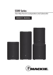
Guided Tour - HT5<br />
1: Audio on-off switch - When set to the “on” position,<br />
audio signal is transmitted. When set to the “off”<br />
position, the audio signal is muted. Because the carrier<br />
signal remains during muting, no “pop” or “thud”<br />
will be heard. Note that turning this off does not<br />
turn off the transmitter power—it is simply a way to<br />
temporarily mute the transmission of audio signal. If<br />
you don’t plan on using the HT5 for extended periods,<br />
turn off its power by using the power on-off switch<br />
(see #3 below).<br />
2: Battery level meter - This set of three multicolor<br />
LEDs indicates relative battery power, indicating<br />
5<br />
whether the installed battery is at low (red), mid<br />
(yellow) or high (green) strength. One or more of<br />
these will light whenever the HT5 is powered on (see<br />
#3 below). When all three are lit, the battery is at<br />
maximum strength. When only the red “low” indicator<br />
lights, RF performance is degraded <strong>and</strong> the battery<br />
needs to be replaced.<br />
3: Power on-off switch* - Use this to turn the HT5 on<br />
or off (to conserve battery power, be sure to leave it<br />
off when not in use).<br />
4: Gain control (trimpot) - This input sensitivity control<br />
has been factory preset to provide optimum level<br />
for the particular microphone capsule provided with<br />
3<br />
ON<br />
MIN MAX<br />
OFF<br />
POWER LEVEL<br />
4<br />
your <strong>Stage</strong> <strong>55</strong> <strong>Series</strong> or <strong>Stage</strong> 5 <strong>Series</strong> system <strong>and</strong> so we recommend that this not be adjusted<br />
manually. If necessary, however, you can use the supplied plastic screwdriver to raise or lower<br />
the input level. See the “<strong>Setting</strong> <strong>Up</strong> <strong>and</strong> <strong>Using</strong> <strong>Your</strong> <strong>Stage</strong> <strong>55</strong> <strong>Series</strong> / STAGE 5 <strong>Series</strong> System” section<br />
on page 12 in this manual for more information.<br />
5: Battery holder - Insert a st<strong>and</strong>ard 9-volt alkaline battery here, being sure to observe the<br />
plus <strong>and</strong> minus polarity markings shown. We recommend the Duracell MN 1604 type battery.<br />
Although rechargeable Ni-Cad batteries can be used, they do not supply adequate current for<br />
more than four hours. WARNING: Do not insert the battery backwards; doing so can cause<br />
severe damage to the HT5 <strong>and</strong> will void your warranty.<br />
* Be sure to mute the audio signal at your external mixer or amplifier before turning transmitter<br />
power on or off, or an audible pop may result.<br />
ENGLISH
ENGLISH<br />
<strong>Setting</strong> <strong>Up</strong> <strong>and</strong> <strong>Using</strong> <strong>Your</strong><br />
<strong>Stage</strong> <strong>55</strong> <strong>Series</strong>/<strong>Stage</strong> 5 <strong>Series</strong> System<br />
The basic procedure for setting up <strong>and</strong> using your <strong>Stage</strong> <strong>55</strong> <strong>Series</strong> or <strong>Stage</strong> 5 <strong>Series</strong> Wireless<br />
System takes only a few minutes:<br />
1. For the <strong>Stage</strong> <strong>55</strong> <strong>Series</strong> / <strong>Stage</strong> 5 <strong>Series</strong> system to work correctly, both the receiver <strong>and</strong> transmitter<br />
must be set to the same channel. Remove all packing materials (save them in case of need<br />
for future service) <strong>and</strong> check to make sure that the supplied receiver <strong>and</strong> transmitter are set to<br />
the same channel. If these channels do not match, contact your distributor or, if purchased in<br />
the United States, <strong>Samson</strong> Technical Support at 1-800-372-6766.<br />
2. Physically place the receiver where it will be used (the general rule of thumb is to maintain<br />
“line of sight” between the receiver <strong>and</strong> transmitter so that the person using or wearing the<br />
transmitter can see the receiver). - Extend the antenna or antennas <strong>and</strong> place them in a vertical<br />
position.<br />
3. Make sure the Power on-off switch in your ST5 belt-pack or HT5 h<strong>and</strong>held transmitter is set to<br />
“Off.”<br />
4a. If your system contains a ST5 belt-pack transmitter, press gently inward on both battery<br />
cover release indents to open the battery door. Note that this door is hinged <strong>and</strong> not intended<br />
to be removed from the transmitter case. Please use care when opening this door as undue<br />
force will destroy the hinge.<br />
4b. If your system contains a HT5 h<strong>and</strong>held transmitter, unscrew the bottom section of the<br />
microphone by turning it counterclockwise <strong>and</strong> then slide it off.<br />
5. Place a fresh 9-volt alkaline battery in the transmitter battery holder, taking care to observe<br />
the polarity markings. If you are using a ST5 belt-pack transmitter, gently replace the battery<br />
door by swinging it up <strong>and</strong> pressing until it clicks. If you are using a HT5 h<strong>and</strong>held transmitter,<br />
replace the bottom section of the microphone by sliding it on <strong>and</strong> then screwing it back on.<br />
Whichever transmitter you are using, leave it off for the moment.<br />
6. Make the physical cable connection between the SR<strong>55</strong> or SR5 output jack <strong>and</strong> the line or mic<br />
level audio input of your amplifier or mixer. If you are using the balanced XLR jack (preferable,<br />
since it will deliver an electromagnetically cleaner signal), be sure to set the receiver rear panel<br />
Audio Output Level switch correctly.If required, both the balanced <strong>and</strong> unbalanced outputs can<br />
be used simultaneously. Leave your amplifier (<strong>and</strong>/or mixer) off at this time.<br />
7. Turn the Volume knob on the SR<strong>55</strong> or SR5 completely counterclockwise. <strong>Using</strong> the strain<br />
relief, connect the supplied AC adapter to the DC Input on the rear panel of the SR<strong>55</strong> or SR5,<br />
then plug the adapter into any st<strong>and</strong>ard AC outlet. Press the front panel Power switch to turn<br />
on the SR<strong>55</strong> or SR5; the green “Power” LED will light up, but all other front panel LEDs will remain<br />
unlit.<br />
8. Turn on the power to the ST5 or HT5 transmitter (using its Power on-off switch); all three<br />
Battery strength LEDs will light if the battery is sufficiently strong. At this point, the RF Meter<br />
on the front panel of the receiver will light. If you are using an SR<strong>55</strong> receiver, either the “A” or “B”<br />
yellow LED on the front panel will also light, depending upon which antenna is receiving the<br />
stronger signal.<br />
10
<strong>Setting</strong> <strong>Up</strong> <strong>and</strong> <strong>Using</strong> <strong>Your</strong><br />
<strong>Stage</strong> <strong>55</strong> <strong>Series</strong>/<strong>Stage</strong> 5 <strong>Series</strong> System<br />
9. Now it’s time to set the audio levels. Turn on your connected amplifier <strong>and</strong>/or mixer but keep<br />
its volume all the way down. Next, make sure that your transmitter is unmuted by setting its<br />
Audio switch to “On.” Then set the Volume knob on the SR<strong>55</strong> or SR5 fully counterclockwise. If you<br />
are using the HT5 transmitter or if you are using the ST5 transmitter with a connected lavaliere<br />
microphone or headset, speak or sing into the mic at a normal performance level while observing<br />
the SR<strong>55</strong> or SR5 front panel Audio Meter. If you are using the ST5 transmitter with a connected<br />
instrument, play the instrument at normal performance level while observing the SR<strong>55</strong> or SR5<br />
front panel Audio Meter. If the “0” (unity gain) segment is lighting steadily, with just occasional<br />
higher excursions, the audio level is correctly set. If not, use the supplied plastic screwdriver to<br />
slowly adjust the HT5, or ST5 Gain control (trimpot) until the SR<strong>55</strong> or SR5 Audio Meter “0” (unity<br />
gain) segment lights steadily (with occasional higher excursions). Then slowly raise the SR<strong>55</strong> or<br />
SR5 Volume knob to the 2 o’clock position (unity gain) <strong>and</strong>, finally, set the volume of your amplifier/mixer<br />
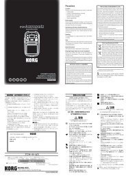
until the desired level is reached. If you are using a ST5 beltpack transmitter equipped<br />
with a lavaliere microphone, note that correct lavaliere placement is critical to sound quality. We<br />
recommend that you place it as shown in the illustration on the right—as close to your mouth as<br />
possible but off to one side (to minimize nasality) <strong>and</strong> unobstructed by clothing. Bear in mind<br />
also that omni microphones (mics which pick up signal<br />
from all directions) are more prone to feedback problems<br />
than unidirectional (cardioid or supercardioid) ones; in<br />
general, you can avoid feedback by taking care not to use<br />
any microphone directly in front of a PA speaker (if this is<br />
unavoidable, try using an equalizer to attenuate those<br />
high- or mid-range frequencies which are causing the<br />
feedback “squealing”).<br />
10. If you hear distortion at the desired volume level (or<br />
if the “+6” segment LED in the Audio Meter is lighting frequently),<br />
first check that the SR<strong>55</strong> or SR5 rear panel Audio<br />
Output Level switch is set correctly. Next, make sure that<br />
the gain structure of your audio system is correctly set<br />
(consult the owners manual of your mixer <strong>and</strong>/or amplifier<br />
for details). If you still hear distortion, do the following:<br />
• If you are using a HT5 h<strong>and</strong>held transmitter or an<br />
ST5 transmitter with connected lavaliere microphone<br />
or headset, its Gain control has been factory preset to provide optimum level for the<br />
particular microphone model being used <strong>and</strong> so no adjustment should be necessary. Any<br />
distortion present should therefore simply be a matter of the microphone being too close to<br />
the mouth; try moving it further away. If this does not solve the problem, use the supplied<br />
plastic screwdriver to turn the Gain control (trimpot) on the HT5 or ST5 slowly counterclockwise<br />
until the distortion disappears.<br />
• If you are using a ST5 transmitter with an instrument such as electric guitar or bass, lower<br />
the output level of the instrument until the distortion disappears. Alternatively, you can use<br />
the supplied plastic screwdriver to turn the Gain control (trimpot) on the ST5 slowly counterclockwise<br />
until the distortion disappears.<br />
Note that, following this setup procedure, you can always lower the Volume knob of the SR<strong>55</strong> or<br />
SR5 in order to further attenuate the output signal if necessary.<br />
11. Conversely, if you hear a weak, noisy signal at the desired volume level (<strong>and</strong> with the Volume<br />
control of the receiver turned fully clockwise), again make sure that the SR<strong>55</strong> or SR5 rear panel<br />
Audio Output Level switch is set correctly <strong>and</strong> that the gain structure of your audio system is<br />
11<br />
ENGLISH
ENGLISH<br />
<strong>Setting</strong> <strong>Up</strong> <strong>and</strong> <strong>Using</strong> <strong>Your</strong><br />
<strong>Stage</strong> <strong>55</strong> <strong>Series</strong>/<strong>Stage</strong> 5 <strong>Series</strong> System<br />
correctly set. If it is <strong>and</strong> the signal coming from the SR<strong>55</strong> or SR5 is still weak <strong>and</strong>/or noisy, do the<br />
following:<br />
• If you are using a HT5 transmitter or an ST5 transmitter with connected lavaliere microphone<br />
or headset, its Gain control has been factory preset to provide optimum level for the<br />
particular microphone model being used <strong>and</strong> so no adjustment should be necessary. Any<br />
weakness of signal should therefore simply be a matter of the microphone being too far<br />
from the mouth; try moving it closer. If this does not solve the problem, use the supplied<br />
plastic screwdriver to turn the Gain control (trimpot) on the HT5 or ST5 slowly clockwise<br />
until the signal reaches an acceptable level.<br />
• If you are using a ST5 transmitter with an instrument such as electric guitar or bass, raise the<br />
output level of the instrument until a good signal is achieved. Alternatively, you can use the<br />
supplied plastic screwdriver to turn the Gain control (trimpot) on the ST5 slowly clockwise<br />
until the signal reaches an acceptable level.<br />
12. Temporarily turn down the level of your mixer/amplifier system <strong>and</strong> turn off the power to<br />
your transmitter, leaving the SR<strong>55</strong> or SR5 on. Then restore the previously set level of your mixer/<br />
amplifier. With the transmitter off, the receiver output should be totally silent—if it is, skip ahead<br />
to the next step. If it isn’t (that is, if you hear some noise), you may need to adjust the receiver’s<br />
front panel Squelch control. When the Squelch control is at its minimum setting, the <strong>Stage</strong><br />
<strong>55</strong> <strong>Series</strong> / <strong>Stage</strong> 5 <strong>Series</strong> system always provides maximum range without dropout; however,<br />
depending upon the particular environment your system is used in, you may need to reduce that<br />
range somewhat in order to eliminate b<strong>and</strong> noise or interference when the transmitter is turned<br />
off. To do so, use the provided screwdriver to rotate the Squelch control completely counterclockwise<br />
(to the “Min” position), then slowly turn it clockwise until the noise disappears. If no<br />
noise is present at any position, leave it at its fully counterclockwise “Min” position (so as to have<br />
the greatest overall range available).<br />
13. When first setting up the <strong>Stage</strong> <strong>55</strong> <strong>Series</strong> or <strong>Stage</strong> 5 <strong>Series</strong> System in a new environment, it’s<br />
always a good idea to do a walkaround in order to make sure that coverage is provided for your<br />
entire performance area. Accordingly, turn down the level of your audio system <strong>and</strong> turn on both<br />
the transmitter <strong>and</strong> receiver. Then, with the transmitter unmuted, restore the level of your audio<br />
system <strong>and</strong> while speaking, singing, or playing your instrument, walk through the entire area that<br />
will need to be covered. As you do so, the “TX” LED on the front panel of the SR<strong>55</strong> or SR5 should<br />
always remain lit. If you are using a <strong>Stage</strong> <strong>55</strong> <strong>Series</strong> system, one of the yellow “A” <strong>and</strong> “B” LEDs on<br />
the SR<strong>55</strong> receiver should always be lit, though occasionally switching to show you which antenna<br />
is receiving the stronger signal. Always try to minimize the distance between transmitter <strong>and</strong><br />
receiver as much as possible so that the strongest possible signal is received from all planned<br />
transmission points. In fixed installations such as A/V or corporate conference rooms or for<br />
extended range applications (where the transmitter <strong>and</strong> receiver are more than 150 feet apart), it<br />
may be desirable to angle the receiver antenna or antennas differently from their vertical position<br />
or to install the receiver in the same room as the transmitters (<strong>and</strong>, if necessary, to extend the<br />
wiring to remote audio equipment).<br />
If you have followed all the steps above <strong>and</strong> are experiencing difficulties, contact your local distributor<br />
or, if purchased in the United States, call <strong>Samson</strong> Technical Support (1-800-372-6766)<br />
between 9 AM <strong>and</strong> 5 PM EST.<br />
12
Introduction<br />
Merci d'avoir fait confiance au système sans fil VHF <strong>Samson</strong> VHF TD <strong>Series</strong> ou VHF <strong>Series</strong> ! Ces<br />
deux produits sont très simples d'emploi, mais nous vous conseillons tout de même de lire ces<br />
quelques pages pour tirer parti de tout leur potentiel.<br />
Un système sans fil est composé d'au moins deux éléments (émetteur et récepteur) qui doivent<br />
être réglés sur le même canal (sur la même haute fréquence) pour fonctionner correctement.*<br />
Le système <strong>Samson</strong> VHF TD <strong>Series</strong> ou VHF <strong>Series</strong> que vous avez acquis fonctionne sur une plage<br />
de fréquence de 173,8 à 213,2 MHz et est équipé d'un récepteur VR3TD ou VR3 ainsi que l'un<br />
des émetteurs suivants : émetteur de ceinture VT3L (pour les microphones cravate et serre-tête),<br />
émetteur de ceinture VT3 (pour instruments) ou microphone main VH3. Pour davantage de<br />
sécurité et pour faciliter leur transport, les systèmes VHF TD <strong>Series</strong> et VHF <strong>Series</strong> sont livrés dans<br />
un boîtier antichoc en plastique polypropylene (voir Annexe B, page 50 pour de plus amples<br />
détails).<br />
L’émetteur de ceinture ST5L est équipé d’un connecteur mini-Jack 3,5 mm permettant l’utilisation<br />
des divers émetteurs de la série <strong>Stage</strong>, dont :<br />
LM5 – Micro cravate à condensateur<br />
HS5 - Micro serre-tête à condensateur<br />
GC5 – Câble guitare/instrument haute résistance<br />
L’émetteur micro main HT5 est équipé de la capsule dynamique <strong>Samson</strong> Q7 au néodyme.<br />
* L'émetteur et le récepteur ont été réglés d'usine sur le même canal.<br />
** Optimisé pour les applications sportives, l'utilisation de ce micro serre-tête étanche est recomm<strong>and</strong>ée<br />
en environnement très humide comme les salles de sport et les centres de remise en forme.<br />
13<br />
FRANÇAIS
FRANÇAIS<br />
Introduction<br />
Le récepteur VR3 du système sans fil VHF <strong>Series</strong> fait appel à la technologie non-diversity, incorpore<br />
une seule antenne pour une plus gr<strong>and</strong>e simplicité d'emploi et des coûts plus faibles. Le<br />
récepteur SR<strong>55</strong> fourni avec le système <strong>Stage</strong> <strong>55</strong> <strong>Series</strong> utilise une technologie avancée appelée<br />
“Diversity”. Le récepteur intègre deux antennes (“Antenne A” et “Antenne B”) et un circuit de<br />
réception. Le circuit haute technologie scanne en permanence les signaux HF avec les deux<br />
antennes et détermine quelle antenne offre la réception la plus claire et la plus puissante<br />
— c’est ce signal qui est alors transmis (sans bruit de commutation) au récepteur. Ce procédé<br />
permet d'obtenir une portée de la liaison sans fil bien plus gr<strong>and</strong>e que ne pourrait l'offrir un<br />
récepteur utilisant une seule antenne et supprime également les problèmes de perte de signal,<br />
d'interférences et de déphasage. En outre, le circuit de liaison sample-<strong>and</strong>-hold assure en<br />
permanence une bonne corrélation de phase sans bruit et sans pop lors de la commutation<br />
de l'antenne. Vous obtenez des performances bien supérieures aux systèmes d'antenne true<br />
diversity et une qualité sonore de haute fidélité quel que soit le système sans fil utilisé. Enfin, le<br />
réducteur de bruit Signetics permet d'offrir un son très clair avec un bruit de fond et un sifflement<br />
réduits au minimum.<br />
Ce manuel vous donne une description détaillée des caractéristiques et fonctions des systèmes<br />
VHF TD <strong>Series</strong> et VHF <strong>Series</strong>, un petit tour d'horizon des éléments qui les composent, les consignes<br />
de configuration et d'utilisation de votre système et leurs caractéristiques techniques. Si<br />
vous avez acquis votre système VHF TD <strong>Series</strong> ou VHF <strong>Series</strong> aux Etats-Unis, remplissez la carte<br />
de garantie fournie et retournez-la nous. Vous pourrez ainsi bénéficier de l'assistance technique<br />
en ligne et recevoir les dernières informations sur les produits <strong>Samson</strong>. Si vous avez acquis votre<br />
système VHF TD <strong>Series</strong> ou VHF <strong>Series</strong> hors des Etats-Unis, contactez votre revendeur local.<br />
14
Tour d'horizon - Façade avant du SR<strong>55</strong><br />
1<br />
2<br />
3 4<br />
5 5<br />
1 : Antennes (A et B) - Les antennes pivotent pour une placement optimal. En fonctionnement<br />
normal, l'antenne A (celle de gauche) et l'antenne B (celle de droite) doivent être placées à la<br />
verticale. Vous pouvez replier les antennes pour faciliter le transport du VR3TD. Reportez-vous<br />
au chapitre "Réglage et utilisation du système VHF TD <strong>Series</strong> / VHF <strong>Series</strong>", page 22, pour de plus<br />
amples détails sur le placement des antennes.<br />
2 : Potentiomètre de volume - Ce potentiomètre permet d'ajuster le niveau des signaux audio<br />
envoyés aux sorties symétrique et asymétrique de la façade arrière. Tournez-le au maximum vers<br />
la droite pour obtenir le niveau de référence.<br />
3 : Afficheur de niveau audio - Cet afficheur (similaire aux Bargraphs utilisés sur les équipements<br />
audio) indique le niveau du signal d’entrée audio. Lorsque le segment “0” est allumé, le<br />
niveau du signal d’entrée est optimisé à gain unitaire ; lorsque le segment “+6” est allumé, le<br />
signal sature. Lorsque seul le segment de gauche “-20” est allumé, le niveau du signal d’entrée<br />
n’est qu’à 10 % de son niveau optimal. Si aucun segment n’est allumé, quasiment aucun signal<br />
n’est reçu. Consultez la section “Configuration et utilisation du système <strong>Stage</strong> <strong>55</strong> <strong>Series</strong> / <strong>Stage</strong><br />
5_<strong>Series</strong>” en page 12 de ce mode d’emploi pour obtenir de plus amples informations.<br />
4 : Réglage de squelch - Ce réglage permet de définir la portée maximale du VR3TD avant perte<br />
du signal audio. Même si vous pouvez l'ajuster à l'aide du tournevis en plastique fourni, il est<br />
recomm<strong>and</strong>é de ne pas toucher au réglage d'usine. Reportez-vous au chapitre "Réglage et utilisation<br />
du système VHF TD <strong>Series</strong> / VHF <strong>Series</strong>", page 22, pour de plus amples détails.<br />
5 : Témoins A/B - Un des deux témoins (correspondant à l'antenne en action, A pour l'antenne<br />
A de gauche et B pour l'antenne B de droite) s'allume en jaune lors de la réception des signaux.<br />
Le VR3TD examine en permanence les deux antennes et sélectionne automatiquement celle qui<br />
reçoit le signal le plus puissant et le plus clair. La commutation du système Diversity est totalement<br />
silencieuse, mais elle permet d’augmenter la portée en éliminant quasiment tous les problèmes<br />
d’interférence et de déphasage.<br />
6 : Afficheur de niveau HF - Cet afficheur (similaire au VU-mètre des appareils audio) vous<br />
indique la force du signal audio reçu. Lorsque le segment “100%” est allumé, le signal HF reçu<br />
est totalement modulé et à niveau optimal. Lorsque seul le segment "10 %" le plus à gauche<br />
s'allume, cela signifie que le signal d'entrée est à 10 % de sa puissance optimale. Si aucun segment<br />
ne s'allume, cela signifie qu'aucun signal n'est reçu ou seulement un signal très faible.<br />
Reportez-vous au chapitre "Réglage et utilisation du système VHF TD <strong>Series</strong> / VHF <strong>Series</strong>", page 22,<br />
pour de plus amples détails.<br />
7 : Interrupteur d'alimentation Power - Il permet des mettre sous et hors tension le VR3TD. Le<br />
témoin d'alimentation s'allume en verte lorsque l'appareil est sous tension.<br />
15<br />
6<br />
1<br />
7<br />
FRANÇAIS
FRANÇAIS<br />
Tour d'horizon - Façade arrière du SR<strong>55</strong><br />
1 2 3 4<br />
1 : Connecteur d'alimentation - Reliez-y l'adaptateur 12 volts 250 mA fourni en veillant à bien<br />
faire le noeud de sécurité comme le montre l'illustration ci-dessous.<br />
AVERTISSEMENT : L'utilisation d'un adaptateur non conforme peut endommager gravement le<br />
VR3TD et annulerait la garantie.<br />
Noeud de sécurité : Faites une boucle avec le cordon et faites la passer dans la sécurité, puis faites<br />
passer la prise du cordon dans la boucle de façon à obtenir un noeud.<br />
2 : Sortie asymétrique* - Cette sortie asymétrique haute impédance (5 kOhms) au format<br />
jack 6,35 mm vous permet de relier le VR3TD à des appareils audio de type domestique (-10).<br />
Câblage : point chaud sur pointe, masse sur corps.<br />
3 : Sélecteur de niveau de sortie audio - Permet d'atténuer le niveau de la sortie symétrique de<br />
-20 dBm (niveau ligne) ou -40 dBm (niveau micro). Reportez-vous au chapitre "Réglage et utilisation<br />
du système VHF TD <strong>Series</strong> / VHF <strong>Series</strong>", page 22, pour de plus amples détails.<br />
4 : Sortie symétrique* - Cette sortie symétrique basse impédance (600 Ohms) au format XLR<br />
vous permet de relier le VR3TD à des appareils audio de type professionnel (+4). Câblage : masse<br />
(blindage) sur broche 1, point chaud sur broche 2 et point froid sur broche 3.<br />
* Vous pouvez utiliser simultanément la sortie symétrique et la sortie asymétrique.<br />
16
1<br />
2<br />
Tour d'horizon - Façade avant du SR5<br />
3 4<br />
5 7<br />
1 : Antenne - L'antenne pivote pour une placement optimal. En fonctionnement normal,<br />
l'antenne doit être placée à la verticale mais vous pouvez la replier pour transporter plus facilement<br />
le VR3. Reportez-vous au chapitre "Réglage et utilisation du système VHF TD <strong>Series</strong> /<br />
VHF <strong>Series</strong>", page 22, pour de plus amples détails sur le placement des antennes.<br />
2 : Potentiomètre de volume - Ce potentiomètre permet d'ajuster le niveau des signaux audio<br />
envoyés aux sorties symétrique et asymétrique de la façade arrière. Tournez-le au maximum vers<br />
la droite pour obtenir le niveau de référence.<br />
3 : Témoin "TXON" - S'allume lorsqu'un signal de porteuse suffisamment puissant est reçu par le<br />
VR3.<br />
4 : Réglage de Squelch - Ce réglage permet de définir la portée maximale du VR3 avant perte<br />
du signal audio. Même si vous pouvez l'ajuster à l'aide du tournevis en plastique fourni, il est<br />
recomm<strong>and</strong>é de ne pas toucher au réglage d'usine. Reportez-vous au chapitre "Réglage et utilisation<br />
du système VHF TD <strong>Series</strong> / VHF <strong>Series</strong>", page 22, pour de plus amples détails.<br />
5 : Afficheur de niveau audio - Cet afficheur (similaire au VU-mètre des appareils audio) vous<br />
indique la puissance du signal audio reçu. Lorsque le segment "100 %" s'allume, le signal<br />
d'entrée est optimisé au gain unitaire ; lorsque le segment "125 %" s'allume, le signal surcharge.<br />
Lorsque seul le segment "10 %" le plus à gauche s'allume, cela signifie que le signal d'entrée est à<br />
10 % de sa puissance optimale. Si aucun segment ne s'allume, cela signifie qu'aucun signal n'est<br />
reçu ou seulement un signal très faible. Reportez-vous au chapitre "Réglage et utilisation du système<br />
VHF TD <strong>Series</strong> / VHF <strong>Series</strong>", page 22, pour de plus amples détails.<br />
6 : Afficheur de niveau HF - Ce témoin s'allume en verte lorsque vous mettez le VR3 sous tension.<br />
7 : Interrupteur d'alimentation Power - Il permet de mettre sous et hors tension le VR3. Le<br />
témoin d'alimentation s'allume en verte lorsque l'appareil est sous tension.<br />
17<br />
6<br />
FRANÇAIS
FRANÇAIS<br />
Tour d'horizon - Façade arrière du SR5<br />
1 2 3 4<br />
1 : Connecteur d'alimentation - Reliez-y l'adaptateur 12 volts 250 mA fourni en veillant à bien<br />
faire le noeud de sécurité comme le montre l'illustration ci-dessous.<br />
Noeud de sécurité : Faites une boucle avec le cordon et faites la passer dans la sécurité, puis faites passer la prise du<br />
cordon dans la boucle de façon à obtenir un noeud.<br />
AVERTISSEMENT : L'utilisation d'un adaptateur non conforme peut endommager gravement le<br />
VRX et annulerait la garantie.<br />
2 : Sortie asymétrique* - Cette sortie asymétrique haute impédance (5 kOhms) au format jack<br />
6,35 mm vous permet de relier le VRX à des appareils audio de type domestique (-10). Câblage :<br />
point chaud sur pointe, masse sur corps.<br />
3 : Sélecteur de niveau de sortie audio - Permet d'atténuer le niveau de la sortie symétrique<br />
de -20 dBm (niveau ligne) ou -40 dBm (niveau micro). Reportez-vous au chapitre "Réglage et<br />
utilisation du système VHF TD <strong>Series</strong> / VHF <strong>Series</strong>", page 22, pour de plus amples détails.<br />
4 : Sortie symétrique* - Cette sortie symétrique basse impédance (600 Ohms) au format XLR<br />
vous permet de relier le VRX à des appareils audio de type professionnel (+4). Câblage : masse<br />
(blindage) sur broche 1, point chaud sur broche 2 et point froid sur broche 3.<br />
* Vous pouvez utiliser simultanément la sortie symétrique et la sortie asymétrique.<br />
18<br />
-
Tour d'horizon - SR5 / ST5<br />
1 : Connecteur d’entrée – Le capteur utilisé est connecté à cette embase. Le ST5 est fourni<br />
avec un micro cravate, un micro serre-tête ou un câble instrument haute résistance en Jack 6,35<br />
mm, connectés à l’émetteur par un mini-Jack 3,5 mm à verrouillage.<br />
2 : Témoins d'usure de la pile - Ces trois diodes vous renseignent sur l'usure de la pile : la diode<br />
rouge s'allume lorsque la pile doit être changée, la diode jaune s'allume lorsque vous avez<br />
consommé la moitié de la pile et la diode verte s'allume lorsque la pile est neuve ou presque.<br />
Une de ces trois diode clignote lors de la mise sous tension du VT3L/VT3 (voir n°5 de la page<br />
suivante). Lorsque la diode rouge "low" clignote, les performances RF baissent et il faut changer<br />
la pile.<br />
3 : Interrupteur Audio - Lorsqu'il est placé sur "on", les signaux audio sont transmis. Lorsqu'il<br />
est placé sur "off", la transmission est coupée. Comme le signal de porteuse reste actif lorsque<br />
la transmission est coupée, aucun bruit parasite n'apparaît. Attention : le fait de faire basculer<br />
l'interrupteur sur "off" ne met pas l'émetteur hors tension (cela coupe simplement la transmission<br />
des signaux audio). Si vous prévoyez de ne pas utiliser l'émetteur pendant une période prolongée,<br />
éteignez-le à l'aide de l'interrupteur d'alimentation Power. (voir n°5 de la page suivante).<br />
4 : Ouverture du compartiment de la pile - Poussez délicatement la trappe tout en appuyant<br />
légèrement sur les deux encoches afin d'ouvrir le compartiment de la pile du VT3L/VT3. Vous<br />
avez ainsi accès à l'interrupteur d'alimentation (voir n°5 de la page suivante) et au potentiomètre<br />
de gain (voir n°6 de la page suivante).<br />
5 : Interrupteur d'alimentation Power* - Il permet de mettre sous et hors tension les VT3L<br />
et VT3. Pour ne pas gaspiller inutilement la pile, veillez à bien mettre le VT3L/VT3 hors tension,<br />
position "off", lorsque vous ne l'utilisez pas.<br />
4<br />
1 2 3<br />
LOW MID HIGH<br />
BATTERY LEVEL<br />
19<br />
AUDIO ON<br />
4<br />
FRANÇAIS
FRANÇAIS<br />
Tour d'horizon - SR5 / ST5<br />
6<br />
7<br />
8<br />
6 : Sélecteur d’atténuation – L’émetteur ST5 est équipé d’un atténuateur de signal pour sélectionner<br />
un niveau d’entrée de “0 dB” ou de “-15 dB”. Cet atténuateur a été réglé d’usine sur “0 dB”<br />
pour permettre un niveau optimal avec la plupart des micros et instruments. Si vous utilisez un<br />
micro ou un instrument avec un niveau de sortie élevé, commencez par régler le niveau de gain<br />
(décrit dans la section précédente). Si vous n’arrivez pas à atténuer suffisamment le niveau du<br />
signal avec le Gain, utilisez le tournevis cruciforme en plastique fourni (voir n° 9 ci-dessous) pour<br />
régler le sélecteur d’atténuation vers la gauche et régler le gain d’entrée du ST5 sur “-15 dB”.<br />
7 : Potentiomètre de gain - Ce réglage de gain d’entrée a été effectué d’usine sur un niveau<br />
nominal. Il est conseillé de ne le modifier que si le niveau du signal est trop faible ou trop élevé.<br />
Nous vous conseillons par conséquent de ne pas le modifier. Il reste possible, néanmoins, de le<br />
modifier à l'aide du tournevis en plastique fourni pour augmenter ou diminuer le niveau d'entrée.<br />
Reportez-vous page 22, pour de plus amples détails.<br />
8 : Compartiment de la pile - Placez-y une pile alcaline 9 volts st<strong>and</strong>ard en respectant bien la<br />
polarité (+ et -). Nous vous recomm<strong>and</strong>ons d'utiliser une pile de type Duracell MN 1604. Même<br />
si vous avez la possibilité d'utiliser des piles Nickel Cadmium rechargeables, celles-ci ne peuvent<br />
fournir la puissance adéquate plus de quatre heures.<br />
AVERTISSEMENT : N'insérez pas la pile à l'envers car cela pourrait endommager gravement le<br />
VT3L/VT3 et annulerait la garantie.<br />
9 : Tournevis en plastique - Ce tournevis permet d'ajuster les réglages du gain du VT3L/VT3<br />
(voir n°7 ci-dessus) et du squelch de l'émetteur (voir n°4 des pages 15 et 17). Reportez-vous au<br />
chapitre "Réglage et utilisation du système VHF TD <strong>Series</strong> / VHF <strong>Series</strong>", page 22, pour de plus<br />
amples détails.<br />
* Veillez à bien couper les signaux audio au niveau du mélangeur et de l'amplificateur avant de mettre<br />
sous ou hors tension l'émetteur pour éviter toute apparition de bruits parasites.<br />
20<br />
5<br />
9
FCC ID CCRHT5<br />
AUDIO<br />
OFF ON<br />
LOW MID HIGH<br />
BATTERY LEVEL<br />
Ch2<br />
2<br />
0168<br />
1<br />
21<br />
Tour d'horizon - HT5<br />
1 : Interrupteur Audio - Lorsqu'il est placé sur "on",<br />
les signaux audio sont transmis. Lorsqu'il est placé<br />
sur "off", la transmission est coupée. Comme le signal<br />
de porteuse reste actif lorsque la transmission est<br />
coupée, aucun bruit parasite n'apparaît. Attention :<br />
le fait de faire basculer l'interrupteur sur "off" ne met<br />
pas l'émetteur hors tension (cela coupe simplement la<br />
transmission des signaux audio). Si vous prévoyez de<br />
ne pas utiliser le VH3 pendant une période prolongée,<br />
éteignez-le à l'aide de l'interrupteur d'alimentation<br />
Power (voir n°3 ci-dessous).<br />
2 : Témoins d'usure de la pile - Ces trois diodes<br />
5<br />
vous renseignent sur l'usure de la pile : la diode rouge<br />
s'allume lorsque la pile doit être changée, la diode<br />
jaune s'allume lorsque vous avez consommé la moitié<br />
de la pile et la diode verte s'allume lorsque la pile est<br />
neuve ou presque. Une de ces trois diode clignote<br />
lors de la mise sous tension du VT3L/VT3 (voir n°3<br />
ci-dessous). Lorsque la diode rouge "low" clignote,<br />
les performances RF baissent et il est nécessaire de<br />
changer la pile.<br />
3 : Interrupteur d'alimentation Power* - Il permet<br />
de mettre sous et hors tension le VH3. Pour ne<br />
pas gaspiller inutilement la pile, veillez à bien mettre<br />
le VH3 hors tension, position "off", lorsque vous ne<br />
l'utilisez pas.<br />
3<br />
ON<br />
MIN MAX<br />
OFF<br />
POWER LEVEL<br />
4<br />
4 : Potentiomètre de gain - La sensibilité à l'entrée a été optimisée d'usine pour<br />
l'utilisation des capsules fournies avec votre VHF TD <strong>Series</strong> ou votre VHF <strong>Series</strong>. Nous vous<br />
conseillons par conséquent de ne pas le modifier. Il reste possible, néanmoins, de le modifier<br />
à l'aide du tournevis en plastique fourni pour augmenter ou diminuer le niveau d'entrée.<br />
Reportez-vous page 22, pour de plus amples détails.<br />
5 : Compartiment de la pile - Placez-y une pile alcaline 9 volts st<strong>and</strong>ard en respectant bien la<br />
polarité (+ et -). Nous vous recomm<strong>and</strong>ons d'utiliser une pile de type Duracell MN 1604. Même<br />
si vous avez la possibilité d'utiliser des piles Nickel Cadmium rechargeables, celles-ci ne peuvent<br />
fournir la puissance adéquate plus de quatre heures.<br />
AVERTISSEMENT : N'insérez pas la pile à l'envers car cela pourrait endommager gravement les<br />
VH3 et annulerait la garantie.<br />
* Veillez à bien couper les signaux audio au niveau du mélangeur ou de l'amplificateur avant de<br />
mettre sous ou hors tension l'émetteur pour éviter toute apparition de bruits parasites.<br />
FRANÇAIS
FRANÇAIS<br />
Réglage et utilisation du système<br />
<strong>Stage</strong> <strong>55</strong> <strong>Series</strong> / <strong>Stage</strong> 5 <strong>Series</strong><br />
La procédure de réglage de base des systèmes sans fil VHF TD <strong>Series</strong> ou VHF <strong>Series</strong> ne prend que<br />
quelques minutes.<br />
1. Pour que les systèmes VHF TD <strong>Series</strong> / VHF <strong>Series</strong> fonctionnent correctement, il faut que le<br />
récepteur et l'émetteur soient réglés sur le même canal. Retirez l'emballage (gardez-le au cas où<br />
l'appareil nécessiterait une réparation) et vérifiez que l'émetteur et le récepteur sont réglés sur le<br />
même canal. Dans le cas contraire, contactez votre revendeur.<br />
2. Placez le récepteur à l'endroit où vous désirez l'utiliser. Il est d'usage de le placer dans un<br />
endroit visible par la personne utilisant ou portant l'émetteur. Un kit de mise en rack optionnel<br />
(disponible chez votre revendeur <strong>Samson</strong>) vous permet d'installer les VR3TD et VR3 dans un rack<br />
19 pouces st<strong>and</strong>ard. Déployez l'antenne et placez-la à la verticale.<br />
3. Vérifiez que l'interrupteur d'alimentation des émetteurs de ceinture <strong>Stage</strong> <strong>55</strong> / <strong>Stage</strong> 5 ou du<br />
microphone main VH3 est bien en position "Off".<br />
4a. Si votre système se compose d'un émetteur de ceinture VT3L ou VT3, ouvrez le compartiment<br />
de la pile en en appuyant délicatement sur les encoches du couvercle et en le faisant<br />
glisser. Attention à ne pas endommager le couvercle en le retirant.<br />
4b. Si votre système se compose d'un microphone main VH3, dévissez le fond du microphone<br />
en le tournant vers la gauche, puis faites-le glisser.<br />
5. Placez une pile alcaline 9 volts neuve dans l'émetteur en respectant bien la polarité indiquée.<br />
Si vous utilisez un émetteur de ceinture VT3L ou VT3, replacez délicatement le couvercle du<br />
compartiment de la pile jusqu'à ce que vous entendiez un clic. Si vous utilisez un microphone<br />
main VH3, replacez le fond du microphone en le faisant glisser, puis en le vissant. Laisser<br />
l'émetteur se charger un moment.<br />
6. Reliez le câble du connecteur de sortie du VR3TD ou du VR3 à l'entrée niveau ligne ou niveau<br />
micro de votre amplificateur ou de votre mélangeur. Si vous utilisez la prise XLR symétrique<br />
(préférable, car elle est moins soumise aux interférences électromagnétiques), veillez à placer<br />
le sélecteur de niveau de sortie sur la bonne position. Vous pouvez, si nécessaire, utiliser simultanément<br />
les sorties symétrique et asymétrique. N'allumez pas encore votre amplificateur ou<br />
votre mélangeur.<br />
7. Tournez le potentiomètre de volume du VR3TD/VR3 au maximum à droite. Reliez<br />
l'adaptateur au connecteur d'alimentation en façade arrière du VR3TD/VR3 en veillant bien<br />
à faire un noeud de sécurité, puis branchez l'adaptateur à une prise secteur. Appuyez sur<br />
l'interrupteur d'alimentation Power de la façade avant pour mettre le VR3TD/VR3 sous tension.<br />
La diode verte "Power" doit s'allumer alors que tous les autres témoins doivent rester éteints.<br />
8. Mettez l'émetteur VT3L, VT3 ou VH3 sous tension (à l'aide de l'interrupteur d'alimentation) ; le<br />
témoin vert "HIGH" s'allume si la pile est suffisamment puissante. À ce moment-là, l’afficheur de<br />
niveau HF de la face avant s’allume. Si vous utilisez un récepteur VR3TD, le témoin jaune "A" ou<br />
"B" de la façade avant se met également à clignoter en fonction de l'antenne qui reçoit le signal<br />
le plus puissant.<br />
9. Passons au réglage des niveaux audio. Mettez l'amplificateur et le mélangeur sous tension<br />
mais laissez leur niveau au minimum. Placez ensuite l'interrupteur Audio sur "On" pour activer<br />
la transmission de l'émetteur. Tournez le potentiomètre Volume du VR3TD/VR3 au maximum à<br />
gauche.Si vous utilisez l’émetteur HT5 ou le ST5 avec un micro cravate ou serre-tête, parlez ou<br />
chantez dans le micro avec le même niveau que vous utiliserez pendant le spectacle et en observant<br />
l’afficheur de niveau audio du SR<strong>55</strong> ou du SR5 (en face avant). Si vous utilisez l’émetteur ST5<br />
avec un instrument, jouez sur l’instrument avec un niveau identique à celui que vous utiliserez<br />
pendant le spectacle en observant l’afficheur de niveau audio du SR<strong>55</strong> ou du SR5 (en face<br />
avant). Si le segment "100 %" (gain unitaire) s'allume en continu avec seules quelques crêtes<br />
22
Réglage et utilisation du système<br />
<strong>Stage</strong> <strong>55</strong> <strong>Series</strong> / <strong>Stage</strong> 5 <strong>Series</strong><br />
plus élevées, le niveau est réglé correctement. Sinon, ajustez lentement le potentiomètre de gain<br />
du VH3, VT3L ou VT3 à l'aide du tournevis en plastique fourni jusqu'à ce que le segment "100 %"<br />
(gain unitaire) de l'afficheur de niveau du VR3TD/VR3 reste allumé en permanence. Amenez<br />
ensuite le potentiomètre de volume du VR3TD/VR3 en position 2 heures (gain unitaire), puis, en<br />
dernier lieu, ajustez le volume de l'amplificateur ou du mélangeur jusqu'à ce que vous obteniez<br />
le niveau désiré. Si vous utilisez un émetteur de ceinture VT3L équipé d'un microphone cravate, la<br />
qualité sonore dépend gr<strong>and</strong>ement de la bonne position du microphone. Nous vous conseillons<br />
de le placer aussi près que possible de votre bouche (voir illustration). Veillez toutefois à ne pas<br />
le placer directement dans l'axe de votre bouche pour ne pas donner de coloration trop nasale<br />
au son ni à placer de vêtement entre votre bouche et le<br />
micro. N'oubliez pas que les micros omnidirectionnels<br />
(qui captent le signal dans toutes les directions) sont plus<br />
enclins aux problèmes de Larsen que les micros unidirectionnels<br />
(cardioïdes ou supercardioïdes). Pour éviter<br />
tout risque d'accrochage, éloignez le plus possible le<br />
microphone des enceintes. Si cela est impossible, servezvous<br />
d'un correcteur pour atténuer les fréquences aiguës<br />
et médiums incriminées.<br />
10. Si vous entendez de la distorsion au volume désiré<br />
(ou si la Led “+6” de l’afficheur de niveau audio s’allume<br />
souvent), commencez par vérifier si le sélecteur de niveau<br />
de sortie en façade arrière est placé sur la bonne position.<br />
Vérifiez ensuite le bon réglage du gain de votre système<br />
audio (consultez le manuel d'utilisation de votre amplificateur<br />
et/ou de votre mélangeur). Si la distorsion persiste,<br />
voici quelques mesures à prendre :<br />
• Si vous utilisez un microphone main VH3 ou un émetteur VT3L relié à un microphone cravate<br />
ou serre-tête, son gain a été optimisé d'usine pour le modèle de microphone utilisé.<br />
Vous n'avez ainsi aucun réglage à faire. Dans ce cas, la distorsion provient sans doute de la<br />
trop gr<strong>and</strong>e proximité du microphone et de la bouche. Essayez par conséquent de repousser<br />
légèrement le microphone. Si le problème persiste, tournez le potentiomètre de gain du<br />
VH3/VT3L légèrement vers la gauche à l'aide du tournevis en plastique fourni jusqu'à ce que<br />
la distorsion disparaisse.<br />
• Si vous utilisez un émetteur VT3 relié à un instrument comme une guitare électrique ou<br />
basse, faites baisser le niveau de sortie de l'instrument jusqu'à ce que la distorsion disparaisse.<br />
Vous pouvez également tourner le potentiomètre de gain du VT3 légèrement vers la<br />
gauche à l'aide du tournevis en plastique fourni jusqu'à ce que la distorsion disparaisse.<br />
Remarque : Vous pouvez toujours faire baisser, si nécessaire, le niveau de sortie du VR3TD/VR3 à<br />
l'aide de son potentiomètre de volume.<br />
11. Inversement, si le signal est faible et le bruit de fond élevé au niveau désiré (alors que le<br />
potentiomètre de volume du récepteur est tourné au maximum à droite), vérifiez que le sélecteur<br />
de niveau de sortie en façade arrière du VR3TD/VR3 est placé sur la bonne position et le bon<br />
réglage du gain de votre système audio. Si le problème persiste, voici quelques mesures à prendre<br />
:<br />
• Si vous utilisez un émetteur VH3 ou VT3L relié à un microphone cravate ou serre-tête, son<br />
gain a été optimisé d'usine pour le modèle de microphone utilisé. Aucun réglage n'est donc<br />
nécessaire. Le problème est probablement dû à la trop gr<strong>and</strong>e distance séparant le micro-<br />
23<br />
FRANÇAIS
FRANÇAIS<br />
Réglage et utilisation du système<br />
<strong>Stage</strong> <strong>55</strong> <strong>Series</strong> / <strong>Stage</strong> 5 <strong>Series</strong><br />
phone et la bouche. Rapprochez donc le microphone. Si le problème persiste, tournez le<br />
potentiomètre de gain du VH3/VT3L légèrement vers la droite à l'aide du tournevis en plastique<br />
fourni jusqu'à ce que le signal atteigne un niveau acceptable.<br />
• Si vous utilisez un émetteur VT3 relié à un instrument comme une guitare électrique ou une<br />
basse, relevez le niveau de sortie de l'instrument jusqu'à ce que vous entendiez un signal de<br />
qualité. Vous pouvez également tourner le potentiomètre de gain du VT3 progressivement<br />
vers la droite à l'aide du tournevis en plastique jusqu'à ce que le signal atteigne un niveau<br />
acceptable.<br />
12. Amenez le niveau de l'amplificateur/mélangeur à zéro puis mettez l'émetteur hors tension<br />
tout en laissant le VR3TD ou le VR3 activé. Ramenez le mélangeur/amplificateur à son niveau<br />
précédent. Lorsque l'émetteur est éteint, la sortie du récepteur doit être totalement silencieuse.<br />
Si elle l'est, passez directement à l'étape suivante. Dans le cas contraire (si vous entendez du<br />
bruit), il faut peut-être ajuster le réglage de squelch situé sur la façade avant du récepteur.<br />
Lorsque le squelch est réglé au minimum, le système VHF TD <strong>Series</strong> / VHF <strong>Series</strong> offre toujours<br />
une portée maximale sans perte de signal. Néanmoins, selon l'environnement dans lequel le<br />
système est utilisé, il peut être nécessaire de réduire légèrement la portée pour supprimer les<br />
bruits de b<strong>and</strong>e ou les interférences qui se produisent lors de la mise hors tension de l'émetteur.<br />
Il suffit pour cela de tourner le potentiomètre de squelch totalement vers la gauche à l'aide du<br />
tournevis fourni (vers la position "Min"), puis de le ramener progressivement vers la droite jusqu'à<br />
ce que le bruit disparaisse. Si vous n'entendez pas de bruit sur quelque position que ce soit, laissez<br />
le potentiomètre totalement sur la gauche en position "Min" (pour pouvoir disposer de la<br />
plus gr<strong>and</strong>e portée offerte).<br />
13. Lorsque vous réglez le système VHF TD <strong>Series</strong> ou VHF <strong>Series</strong> pour la première fois dans un<br />
nouvel environnement, il est conseillé de tester le bon fonctionnement du système à tous les<br />
points du site. Pour cela, baissez le niveau de votre système audio, puis mettez l'émetteur et le<br />
récepteur sous tension. Vérifiez que les transmissions de l'émetteur ne sont pas coupées, puis<br />
ramenez le système audio à son niveau précédent. Tout en parlant, chantant ou jouant de votre<br />
instrument, déplacez-vous sur la totalité de la zone à couvrir. Pendant ce temps, le témoin "TX"<br />
de la façade avant du VR3TD/VR3 doit toujours rester éclairé. Si vous utilisez un système VHF TD<br />
<strong>Series</strong>, il faut que l'un des deux témoins jaune "A" ou "B" du récepteur VR3TD reste en permanence<br />
éclairé, même lors du basculement éventuel d'une antenne de réception à l'autre. Veillez<br />
toujours à réduire au minimum la distance qui sépare l'émetteur du récepteur pour que le signal<br />
reçu de tous les points de transmission indiqués soit toujours le plus fort possible. Dans les installations<br />
fixes comme les structures audiovisuelles, les salles de conférence ou pour les applications<br />
mettant en jeu de gr<strong>and</strong>es distances (lorsque l'émetteur et le récepteur sont éloignés de<br />
plus de 500 mètres), il est recomm<strong>and</strong>é d'incliner la ou les antennes de réception et d'installer le<br />
récepteur et les émetteurs dans la même pièce (et, si nécessaire, de rallonger les câbles jusqu'au<br />
appareils audio distants).<br />
Si, malgré tout, vous continuez de rencontrer des problèmes, veuillez contacter votre revendeur<br />
<strong>Samson</strong>.<br />
24
Einleitung<br />
Wir wollen Ihnen zum Erwerb des SAMSON VHF TD <strong>Series</strong> bzw. VHF <strong>Series</strong> Drahtlossystem gratulieren<br />
und uns herzlich bei Ihnen bedanken. Obwohl dieses Produkt auf einfache H<strong>and</strong>habung<br />
ausgelegt ist, empfehlen wir Ihnen, sich diese Anleitung vor Inbetriebnahme zunächst sorgfältig<br />
und vollständig durchzulesen, damit Sie alle Eigenschaften dieses Gerätes verstehen und es so<br />
optimal nutzen können.<br />
Drahtlose Übertragungssysteme bestehen aus mindestens zwei Komponenten, nämlich<br />
einem Sender und einem Empfänger, die auf den gleichen Kanal (d. h. die gleiche Sende-<br />
/Empfangsfrequenz) eingestellt sein müssen, um ordnungsgemäß zu funktionieren. Das von<br />
Ihnen erworbene VHF TD <strong>Series</strong> / VHF <strong>Series</strong> arbeitet in einem Frequenzbereich von 173,8 bis<br />
213,2 MHz und beinhaltet einen VR3TD- bzw. VR3-Empfänger und den Sender VT3L (welcher<br />
sich mit Ansteck- oder Headset-Mikrofonen einsetzten läßt), den Sender VT3 (zur Verbindung<br />
mit Instrumenten) oder den Sender VH3, welcher in ein drahtloses H<strong>and</strong>mikrofon integriert ist.<br />
Aus Gründen der Sicherheit und H<strong>and</strong>lichkeit werden die Systeme VHF TD <strong>Series</strong> und VHF <strong>Series</strong><br />
mit einer passenden schlagfesten Plastikhülle ausgeliefert, die Platz für alle Best<strong>and</strong>teile des<br />
Systems bietet (weitere Informationen finden Sie in Anhang B auf Seite 50).<br />
Anschluss an Der ST5L Gürtel-Sender verfügt über eine arretierbare 3.5 mm Mini-Klinkenbuchse<br />
zum die verschiedenen Sender der <strong>Stage</strong>-Serie, inklusive:<br />
LM5 - Lavalier Kondensator-Mikrofon<br />
HS5 – Headset Kondensator-Mikrofon<br />
GC5 – Hoch belastbares Gitarren-/Instrumentenkabel<br />
Der h<strong>and</strong>gehaltene HT5 Mikrofon-Sender ist mit dem <strong>Samson</strong> Q7 Neodym Dynamikmikrofon-<br />
Element ausgestattet.<br />
* Die zu Ihrem System gehörenden Sende- und Empfängereinheiten wurden werksseitig auf den gleichen<br />
Kanal eingestellt.<br />
** Bei den Kopfbügelmikrofonen Audio-Technica Pro-8HE und <strong>Samson</strong> QE h<strong>and</strong>elt es sich um<br />
Spezialmodelle, die für Anwendungen in Umgebungen mit hoher Feuchtigkeit (wie beispielsweise<br />
Fitness-Studios u. ä.) konzipiert wurden.<br />
25<br />
DEUTSCHE
DEUTSCHE<br />
Einleitung<br />
Der dem VHF <strong>Series</strong>-System beiliegende Empfänger VR3 arbeitet auf der Basis der Non-Diversity<br />
Technology und verfügt nur über eine Antenne, was die H<strong>and</strong>habung erleichtert und die Kosten<br />
reduziert. Der mit den Systemen der <strong>Stage</strong> <strong>55</strong> Serie gelieferte SR<strong>55</strong> Empfänger arbeitet mit<br />
der fortschrittlichen “Diversity” Technik, bei der in einem Chassis zwei Antennen (“Antenne A”<br />
und “Antenne B”) und eine Empfänger-Schaltung untergebracht sind. Die komplexe Schaltung<br />
untersucht ständig die RF-Signale der beiden Antennen und entscheidet, welche den klarsten<br />
und stärksten Empfang besitzt. Dieses Signal wird dann automatisch (und geräuschlos) auf<br />
den Empfänger geschaltet. Ein eingebauter Computerchip tastet die Trägersignale der beiden<br />
Antennen kontinuierlich ab, bestimmt, welche der beiden Antennen einen besseren Empfang<br />
hat, und schaltet dieses Signal automatisch (und unhörbar) auf den Empfänger. Dadurch ist der<br />
Nutzbereich des Empfängers weitaus größer als bei einem Empfänger mit nur einer Antenne,<br />
und Signalausfälle, Störgeräusche und Phasenauslöschungen werden vollständig unterbunden.<br />
Weiterhin sorgt ein besonderer S/H-Schaltkreis dafür, daß eine korrekte Phasenlage fortwährend<br />
garantiert ist und keine Rausch- oder Klickgeräusche beim Umschalten zwischen den<br />
Antennen auftreten können. Daraus resultiert eine Leistungsfähigkeit, die der konventioneller<br />
Drahtlosmikrofone mit True Diversity-Technologie in hohem Maße überlegen ist und höchste<br />
Klangqualität garantiert. Abschließend sei angemerkt, daß das in alle Systeme integrierte Rausc<br />
hunterdrückungssystem Signetics® einen kristallklaren Klang garantiert, der praktisch frei ist von<br />
Hintergrund- und Störgeräuschen.<br />
In diesem H<strong>and</strong>buch finden Sie eine ausführliche Beschreibung der Eigenschaften des VHF TD<br />
<strong>Series</strong> bzw. VHF <strong>Series</strong>, eine Übersicht über alle Systemkomponenten, schrittweise Anweisungen<br />
zu Aufstellung und Betrieb des Systems sowie die technischen Daten. Sollten beim Betrieb der<br />
Systeme VHF TD <strong>Series</strong> oder VHF <strong>Series</strong> Betriebsstörungen oder Probleme auftreten, so wenden<br />
Sie sich an Ihren Kundendienst oder an den SAMSON-Vertrieb Ihres L<strong>and</strong>es. Dort erhalten Sie<br />
auch Informationen zu den Garantieleistungen.<br />
26
1<br />
2<br />
Übersicht: SR<strong>55</strong> Vorderseite<br />
3 4<br />
1. Antennen (A und B) - Die Antennenhalter haben einen Drehradius von 360°, um eine optimale<br />
Aufstellung zu erlauben. Bei normalem Betrieb sollten die beiden Antennen A (links) und<br />
B (rechts) senkrecht aufgestellt werden. Die Antennen lassen sich zum Transport des VR3TD<br />
einschieben. Weitere Informationen über Aufstellung und Betrieb der Antennen erhalten Sie<br />
unter der Überschrift „Aufbau und Betrieb des VHF TD <strong>Series</strong> / VHF <strong>Series</strong>“ auf Seite 34 in dieser<br />
Anleitung.<br />
2. Lautstärkeregler - Mit diesem Regler stellen Sie den Pegel des Audiosignals ein, welches<br />
über die symmetrierten und die unsymmetrierten Anschlüsse auf der Rückseite des Empfängers<br />
ausgegeben wird. Der Referenzpegel ist eingestellt, wenn der Regler am rechten Anschlag steht<br />
(Einstellung „10“).<br />
3. Audio-Pegelanzeige – Diese “Balken”-Anzeige (vergleichbar mit der VU Balkenanzeige von<br />
Audiogeräten) gibt die Stärke des eingehenden Audiosignals an. Wenn das “0” Segment leuchtet,<br />
ist das eingehende Signal auf Unity Gain optimiert. Wenn das “+6” Segment leuchtet, überlastet<br />
das Signal den Eingang. Wenn nur das “-20”_Segment ganz links leuchtet, besitzt das Signal nur<br />
10% seiner optimalen Stärke. Wenn keine Segmente leuchten, wird nur ein schwaches oder kein<br />
Signal empfangen. Wegen näherer Einzelheiten siehe Abschnitt “<strong>Stage</strong> <strong>55</strong> <strong>Series</strong> / <strong>Stage</strong> 5_<strong>Series</strong><br />
System einrichten und einsetzen” auf Seite 12 dieses H<strong>and</strong>buchs.<br />
4. Squelch-Regler - Dieser Regler bestimmt den maximalen Empfangsbereich des VR3TD<br />
vor dem Abschneiden des Audiosignals. Obwohl Sie den Regler mit Hilfe des beiliegenden<br />
Plastikschraubdrehers einstellen können, empfehlen wir Ihnen, die werksseitige Einstellung beizubehalten.<br />
Weitere Informationen erhalten Sie unter der Überschrift „Aufbau und Betrieb des<br />
VHF TD <strong>Series</strong> / VHF <strong>Series</strong>“ auf Seite 34 in dieser Anleitung.<br />
5. A/B-LEDs - Wenn ein Signal empfangen wird, leuchtet eine dieser beiden LEDs gelbe auf<br />
und zeigt so an, welche der beiden Antennen A (links) und B (rechts) gerade verwendet wird.<br />
Der VR3TD prüft das Empfangssignal beider Antennen kontinuierlich und wählt automatisch<br />
das stärkere und damit klarere Empfangssignal aus. Diese Microprocessor Diese Diversity<br />
Umschaltung ist völlig geräuschlos und vergrößert effektiv den Gesamtbereich, wobei potentielle<br />
Interferenzen und Probleme mit Phasen-Auslöschungen fast völlig ausgeschaltet werden.<br />
6. RF Anzeige- Diese LED-Kette arbeitet ähnlich wie die Aussteuerungsanzeige bei<br />
Audiogeräten und zeigt die Stärke des empfangenen Audiosignals an. Wenn das “100%” Segment<br />
leuchtet, wird das eingehende RF Signal voll moduliert und besitzt optimale Stärke.Leuchtet die<br />
„125%“-Anzeige, so ist das Audiosignal übersteuert. Wenn nur das „10%“-Segment leuchtet, hat<br />
das empfangene Audiosignal einen Pegel, der nur zehn Prozent des optimalen Pegels beträgt.<br />
Leuchtet gar kein Segment, so wird ein zu schwaches oder gar kein Signal empfangen. Weitere<br />
Informationen erhalten Sie unter der Überschrift „Aufbau und Betrieb des VHF TD <strong>Series</strong> /<br />
VHF <strong>Series</strong>“ auf Seite 34 in dieser Anleitung.<br />
7. Netzschalter - Mit diesem Schalter schalten Sie den VR3TD ein und aus. Wenn das Gerät<br />
eingeschaltet ist, leuchtet die Power-LED.<br />
27<br />
6<br />
5 5<br />
1<br />
7<br />
DEUTSCHE
DEUTSCHE<br />
Übersicht: SR<strong>55</strong> Rückseite<br />
1 2 3 4<br />
1. Anschluß für das Netzteil - Schließen Sie hier das beiliegende Netzteil wie unten dargestellt<br />
an. ACHTUNG: Verwenden Sie niemals ein <strong>and</strong>eres als das beiliegende Netzgerät, da ansonsten<br />
der VR3TD beschädigt werden könnte und Ihre Garantie erlischt.<br />
2. Audioausgang (unsymmetriert) - Verbinden Sie Audiogeräte, an die Signale mit einem Pegel<br />
von –10 dB (Consumer-Pegel) angeschlossen werden müssen, über diesen Anschluß mit dem<br />
VR3TD. Die Ausgangsimpedanz beträgt 5 k(.<br />
3. Einstellschalter für den Ausgangspegel - Mit diesem Schalter stellen Sie die Abschwächung<br />
des Ausgangssignals für den symmetrierten Ausgang (4) auf –20 dBm (Line-Pegel) oder –40<br />
dBm (Mikrofonpegel) ein. Weitere Informationen erhalten Sie unter der Überschrift „Aufbau und<br />
Betrieb des VHF TD <strong>Series</strong> / VHF <strong>Series</strong>“ auf Seite 34 in dieser Anleitung.<br />
4. Audioausgang (symmetriert) - Verbinden Sie Audiogeräte, an die Signale mit einem Pegel<br />
von +4 dB (Professional-Pegel) angeschlossen werden müssen, über diesen Anschluß mit dem<br />
VR3TD. Die Ausgangsimpedanz beträgt 600 (. Die Belegung der Stifte ist wie folgt: Pin 1 - Erde;<br />
Pin 2 - +-Pol; Pin 3 - –Pol.<br />
* Falls notwendig, können Sie den unsymmetrierten und den symmetrierten Ausgang gleichzeitig<br />
verwenden.<br />
28
1<br />
Übersicht: SR5 Vorderseite<br />
1. Antenne - Der Antennenhalter hat einen Drehradius von 360°, um eine optimale Aufstellung<br />
zu erlauben. Bei normalem Betrieb sollte die Antenne senkrecht aufgestellt werden. Sie läßt sich<br />
zum Transport des VR3 einschieben. Weitere Informationen über Aufstellung und Betrieb der<br />
Antenne erhalten Sie unter der Überschrift „Aufbau und Betrieb des VHF TD <strong>Series</strong> / VHF <strong>Series</strong>“<br />
auf Seite 34 in dieser Anleitung.<br />
2. Lautstärkeregler - Mit diesem Regler stellen Sie den Pegel des Audiosignals ein, welches<br />
über die symmetrierten und die unsymmetrierten Anschlüsse auf der Rückseite des Empfängers<br />
ausgegeben wird. Der Referenzpegel ist eingestellt, wenn der Regler am rechten Anschlag steht<br />
(Einstellung „10“).<br />
2<br />
3 4<br />
5 7<br />
3. “TXON”-LED - Diese LED leuchtet, wenn der VR3 ein ausreichend starkes Signal empfängt.<br />
4. Squelch-Regler - Dieser Regler bestimmt den maximalen Empfangsbereich des VR3<br />
vor dem Abschneiden des Audiosignals. Obwohl Sie den Regler mit Hilfe des beiliegenden<br />
Plastikschraubdrehers einstellen können, empfehlen wir Ihnen, die werksseitige Einstellung beizubehalten.<br />
Weitere Informationen erhalten Sie unter der Überschrift „Aufbau und Betrieb des<br />
VHF TD <strong>Series</strong> / VHF <strong>Series</strong>“ auf Seite 34 in dieser Anleitung.<br />
5. RF Anzeige - Diese LED-Kette arbeitet ähnlich wie die Aussteuerungsanzeige bei<br />
Audiogeräten und zeigt die Stärke des empfangenen Audiosignals an. Wenn das “100%” Segment<br />
leuchtet, wird das eingehende RF Signal voll moduliert und besitzt optimale Stärke. Leuchtet die<br />
„125%“-Anzeige, so ist das Audiosignal übersteuert. Wenn nur das „10%“-Segment leuchtet, hat<br />
das empfangene Audiosignal einen Pegel, der nur zehn Prozent des optimalen Pegels beträgt.<br />
Leuchtet gar kein Segment, so wird ein zu schwaches oder gar kein Signal empfangen. Weitere<br />
Informationen erhalten Sie unter der Überschrift „Aufbau und Betrieb des VHF TD <strong>Series</strong> /<br />
VHF <strong>Series</strong>“ auf Seite 34 in dieser Anleitung.<br />
6. Power-LED - Diese Anzeige leuchtet, wenn der VR3 eingeschaltet ist.<br />
7. Netzschalter - Mit diesem Schalter schalten Sie den VR3 ein und aus. Wenn das Gerät eingeschaltet<br />
ist, leuchtet die Power-LED .<br />
29<br />
6<br />
DEUTSCHE
DEUTSCHE<br />
Übersicht: SR5 Rückseite<br />
1 2 3 4<br />
1. Anschluß für das Netzteil - Schließen Sie hier das beiliegende Netzteil wie unten dargestellt<br />
an. ACHTUNG: Verwenden Sie niemals ein <strong>and</strong>eres als das beiliegende Netzgerät, da ansonsten<br />
der VRX beschädigt werden könnte und Ihre Garantie erlischt.<br />
Verwendung der Zugsicherung: Ziehen Sie zunächst eine Kabelschlinge durch die Zugsicherung.<br />
Schieben Sie dann den Netzteilanschluß durch die Schlinge und ziehen Sie diesen Knoten<br />
vorsichtig zu.<br />
2. Audioausgang (unsymmetriert) - Verbinden Sie Audiogeräte, an die Signale mit einem<br />
Pegel von –10 dB (Consumer-Pegel) angeschlossen werden müssen, über diesen Anschluß mit<br />
dem VRX Die Ausgangsimpedanz beträgt 5 k(.<br />
3. Einstellschalter für den Ausgangspegel - Mit diesem Schalter stellen Sie die Abschwächung<br />
des Ausgangssignals für den symmetrierten Ausgang (4) auf –20 dBm (Line-Pegel) oder –40<br />
dBm (Mikrofonpegel) ein. Weitere Informationen erhalten Sie unter der Überschrift „Aufbau und<br />
Betrieb des VHF TD <strong>Series</strong> / VHF <strong>Series</strong>“ auf Seite 34 in dieser Anleitung.<br />
4. Audioausgang (symmetriert) - Verbinden Sie Audiogeräte, an die Signale mit einem Pegel<br />
von +4 dB (Professional-Pegel) angeschlossen werden müssen, über diesen Anschluß mit dem<br />
VRX. Die Ausgangsimpedanz beträgt 600 (. Die Belegung der Stifte ist wie folgt: Pin 1 - Erde; Pin<br />
2 - +-Pol; Pin 3 - –Pol.<br />
* Falls notwendig, können Sie den unsymmetrierten und den symmetrierten Ausgang gleichzeitig<br />
verwenden.<br />
30<br />
-
31<br />
Übersicht -SR5 / ST5<br />
1. Input-Anschluss – Hier schließen Sie das Eingangs-Gerät an. Der ST5 ist entweder mit einem<br />
Lavalier Headset-Mikrofon oder einem hoch belastbaren Instrumentenkabel ausgerüstet,<br />
das mit einem 1/4” Stecker abschließt. Beide werden über eine arretierbare 3.5 mm Mini-<br />
Klinkenbuchse an den Sender angeschlossen.<br />
2. Batterieanzeige - Diese drei LEDs zeigen die relative Leistungsfähigkeit der eingesetzten<br />
Batterie an. Ist die Batterie voll aufgeladen, so leuchtet die grüne LED. Eine mittlere<br />
Leistungsfähigkeit wird durch die gelbe LED signalisiert, während eine fast vollständig entladene<br />
Batterie durch die rote LED angezeigt wird. Sobald der Sender eingeschaltet wird, leuchtet<br />
eine dieser LEDs. Wenn die rote LED leuchtet, sollten Sie die Batterie austauschen.<br />
3. Audio On/Off-Schalter - Wenn dieser Schalter in der Stellung „On“ steht, wird das<br />
Audiosignal gesendet. Steht der Schalter dagegen in der Einstellung „Off“, so wird das Signal<br />
nicht übertragen. Da jedoch das Trägersignal auch in der „Off“-Stellung gesendet wird, werden<br />
beim Ein- und Ausschalten keine Nebengeräusche hörbar. Beachten Sie, daß bei Ausschalten<br />
dieses Schalters nicht der Sender selbst abgeschaltet wird; der Schalter dient lediglich dazu,<br />
das Audiosignal vorübergehend stummzuschalten. Wenn Sie den Sender für längere Zeit nicht<br />
benutzen wollen, verwenden Sie zum Abschalten den Power-Schalter (5).<br />
4. Batterieabdeckung - Drücken Sie vorsichtig auf die beiden Einschnitte in der Abdeckung,<br />
um das Batteriefach zu öffnen. Sie gelangen so auch an den Power-Schalter (5) und den Gain-<br />
Regler (6).<br />
5. Power-Schalter - Schalten Sie den Sender mit diesem Schalter ein und aus. Wenn Sie<br />
den Sender für längere Zeit nicht verwenden, schalten Sie den Schalter aus („Off“), um die<br />
Lebensdauer der eingelegten Batterie zu verlängern.<br />
4<br />
1 2 3<br />
LOW MID HIGH<br />
BATTERY LEVEL<br />
AUDIO ON<br />
4<br />
DEUTSCHE
DEUTSCHE<br />
Übersicht - SR5 / ST5<br />
6<br />
7<br />
8<br />
6. Attenuation-Schalter – Mit dem Attenuation-Schalter des ST5 Senders können Sie zur<br />
Signalbedämpfung einen Eingangspegel von “0dB” oder “-15dB” wählen. Dieser Attenuation-<br />
Schalter wurde werkseitig auf “0dB” voreingestellt und liefert den optimalen Pegel für die<br />
meisten Mikrofon- und Instrumenten-Eingangssignale. Bei Mikrofonen oder Instrumenten mit<br />
hohem Ausgangspegel sollten Sie zuerst den Gain-Regler einstellen (siehe folgender Abschnitt).<br />
Falls Sie das Signal mit dem Gain-Regler nicht stark genug bedämpfen können, drehen Sie den<br />
Attenuation-Drehregler mit dem beiliegenden Plastik-Schraubenzieher (siehe Nr. 9 unten) ganz<br />
nach links, wodurch der ST5 auf einen Pegel von “-15dB” eingestellt wird.<br />
7. Gain-Regler - Dieser Eingangs-Gain-Regler wurde werkseitig auf Nominalpegel eingestellt<br />
und sollte nur verändert werden, wenn Ihr Signal zu stark oder zu schwach ist. Aus diesem<br />
Grund empfehlen wird, die Einstellung nicht zu ändern. Falls eine Änderung des Pegels dennoch<br />
notwendig werden sollte, können Sie diese mit Hilfe des beiliegenden Plastikschraubdrehers<br />
vornehmen. Weitere Informationen erhalten Sie unter der Überschrift „Aufbau und Betrieb des<br />
VHF TD <strong>Series</strong> / VHF <strong>Series</strong>“ auf Seite 34.<br />
8. Batteriefach - Legen Sie hier eine normale 9-V-Batterie ein. Beachten Sie beim Einlegen die<br />
Polarität der Batterie (+ und –). Sie können zwar wiederaufladbare Batterien (NiCad-Akkus) verwenden,<br />
allerdings reduziert sich dann die maximale Betriebszeit auf nicht mehr als vier Stunden.<br />
ACHTUNG: Legen Sie die Batterien niemals umgedreht in den Sender ein, da ansonsten der<br />
VT3L/VT3 beschädigt werden könnte und Ihre Garantie erlischt.<br />
9. Plastikschraubdreher - Dieser Schraubdreher dient der Bedienung des Eingangspegelreglers<br />
am Sender (7) und/oder des Squelch-Reglers am Empfänger (siehe unter 4 auf den Seiten 27 und<br />
29). Weitere Informationen erhalten Sie unter der Überschrift „Aufbau und Betrieb des VHF TD<br />
<strong>Series</strong> / VHF <strong>Series</strong>“ auf Seite 34 in dieser Anleitung.<br />
* Vergewissern Sie sich, daß das Audiosignal an Ihrem Mischpult oder Verstärker stummgeschaltet ist,<br />
bevor Sie den Sender abschalten, da ansonsten ein hörbares Knacken entsteht.<br />
32<br />
5<br />
9
FCC ID CCRHT5<br />
AUDIO<br />
OFF ON<br />
LOW MID HIGH<br />
BATTERY LEVEL<br />
Ch2<br />
2<br />
0168<br />
1<br />
33<br />
Übersicht - HT5<br />
1. Audio On/Off-Schalter - Wenn dieser Schalter in<br />
der Stellung „On“ steht, wird das Audiosignal gesendet.<br />
Steht der Schalter dagegen in der Einstellung<br />
„Off“, so wird das Signal nicht übertragen. Da jedoch<br />
das Trägersignal auch in der „Off“-Stellung gesendet<br />
wird, werden beim Ein- und Ausschalten keine<br />
Nebengeräusche hörbar. Beachten Sie, daß bei<br />
Ausschalten dieses Schalters nicht der Sender selbst<br />
abgeschaltet wird; der Schalter dient lediglich dazu,<br />
5<br />
das Audiosignal vorübergehend stummzuschalten.<br />
Wenn Sie den Sender für längere Zeit nicht benutzen<br />
wollen, verwenden Sie zum Abschalten den Power-<br />
Schalter (3).<br />
2. Batterieanzeige - Diese drei LEDs zeigen die relative<br />
Leistungsfähigkeit der eingesetzten Batterie an.<br />
Ist die Batterie voll aufgeladen, so leuchtet die grüne<br />
LED. Eine mittlere Leistungsfähigkeit wird durch die<br />
gelbe LED signalisiert, während eine fast vollständig<br />
entladene Batterie durch die rote LED angezeigt wird.<br />
Sobald der Sender eingeschaltet wird, leuchtet eine<br />
dieser LEDs. Wenn die rote LED leuchtet, sollten Sie<br />
die Batterie austauschen.<br />
3<br />
ON<br />
MIN MAX<br />
OFF<br />
POWER LEVEL<br />
4<br />
3. Power-Schalter - Schalten Sie den Sender mit diesem Schalter ein und aus. Wenn Sie<br />
den Sender für längere Zeit nicht verwenden, schalten Sie den Schalter aus („Off“), um die<br />
Lebensdauer der eingelegten Batterie zu verlängern.<br />
4. Gain-Regler - Dieser Regler bestimmt die Eingangsempfindlichkeit des Senders und wurde<br />
werksseitig optimal für die mitgelieferte Mikrofonkapsel eingestellt. Aus diesem Grund empfehlen<br />
wird, die Einstellung nicht zu ändern. Falls eine Änderung des Pegels dennoch notwendig<br />
werden sollte, können Sie diese mit Hilfe des beiliegenden Plastikschraubdrehers vornehmen.<br />
Weitere Informationen erhalten Sie unter der Überschrift „Aufbau und Betrieb des VHF TD <strong>Series</strong><br />
/ VHF <strong>Series</strong>“ auf Seite 34.<br />
5. Batteriefach - Legen Sie hier eine normale 9-V-Batterie ein. Beachten Sie beim Einlegen<br />
die Polarität der Batterie (+ und –). Sie können zwar wiederaufladbare Batterien (NiCad-Akkus)<br />
verwenden, allerdings reduziert sich dann die maximale Betriebszeit auf nicht mehr als vier<br />
Stunden. ACHTUNG: Legen Sie die Batterien niemals umgedreht in den Sender ein, da ansonsten<br />
der VH3 beschädigt werden könnte und Ihre Garantie erlischt.<br />
* Vergewissern Sie sich, daß das Audiosignal an Ihrem Mischpult oder Verstärker stummgeschaltet ist,<br />
bevor Sie den Sender abschalten, da ansonsten ein hörbares Knacken entsteht.<br />
Sie benötigen nur ein paar Minuten, um das VHF TD <strong>Series</strong> /VHF <strong>Series</strong>-System betriebsbereit zu<br />
machen. Gehen Sie wie folgt vor:<br />
DEUTSCHE
DEUTSCHE<br />
Aufbau und Betrieb des<br />
<strong>Stage</strong> <strong>55</strong> <strong>Series</strong> / <strong>Stage</strong> 5 <strong>Series</strong><br />
1. Damit das System korrekt arbeiten kann, ist es notwendig, daß der Sende-/<br />
Empfangskanal von Sender und Empfänger übereinstimmen. Entfernen Sie zunächst alle<br />
Verpackungsmaterialien (bewahren Sie diese jedoch für den Fall auf, daß Sie sie irgendwann<br />
noch einmal benötigen) und vergewissern Sie sich, daß die Kanäle des Senders und<br />
des Empfängers übereinstimmen. Sollte dies nicht der Fall sein, so wenden Sie sich an Ihren<br />
Kundendienst oder den SAMSON-Vertrieb Ihres L<strong>and</strong>es.<br />
2. Plazieren Sie den Empfänger an der geeigneten Stelle. Als Faustregel gilt, daß zwischen<br />
Sender und Empfänger „Sichtkontakt“ bestehen sollte. Sie können den VR3TD/VR3 auch mit<br />
Hilfe eines optional erhältlichen Adapters in ein 19“-St<strong>and</strong>ardrack einbauen. Ziehen Sie die<br />
Antenne bzw. die Antennen des Empfängers vollständig aus und bringen Sie sie in eine senkrechte<br />
Position.<br />
3. Vergewissern Sie sich, daß der Netzschalter des Empfängers und der Power-Schalter des<br />
Senders auf „Off“ stehen.<br />
4a. für die Sender VT3L und VT3: Drücken Sie die Einschnitte der Batterieabdeckung nach unten,<br />
um diese zu öffnen. Die Abdeckung ist mit einem Scharnier versehen. Gehen Sie vorsichtig vor,<br />
um das Scharnier nicht abzubrechen.<br />
4b. für den Sender VH3: Schrauben Sie den unteren Teil des Mikrofons gegen den Uhrzeigersinn<br />
auf und ziehen Sie ihn dann ab.<br />
5. Setzen Sie eine neue 9-V-Batterie in das Batteriefach. Beachten Sie dabei die Polaritätsmarken.<br />
Falls Sie einen der Sender VT3L oder VT3 verwenden, klappen Sie die Batterieabdeckung wieder<br />
zu und schließen Sie sie mit leichtem Druck. Falls Sie den Sender VH3 verwenden, setzen Sie den<br />
unteren Teil des Mikrofons wieder auf und schrauben Sie ihn im Uhrzeigersinn fest. Lassen Sie<br />
den Sender zunächst abgeschaltet.<br />
6. Verbinden Sie nun den Audioausgang des Empfängers VR3TD/VR3 mit dem entsprechenden<br />
LINE- bzw. MIC-Eingang Ihres Mischpults oder Verstärkers. Wir empfehlen Ihnen, den symmetrierten<br />
XLR-Ausgang des VR3TD/VR3 zu verwenden, da dieses Signal qualitativ hochwertiger ist<br />
als das des unsymmetrierten Ausgangs. Falls Sie den XLR-Ausgang verwenden, vergewissern<br />
Sie sich, daß der Einstellschalter für den Ausgangspegel korrekt eingestellt ist. Falls notwendig,<br />
können Sie auch beide Ausgänge gleichzeitig nutzen. Schalten Sie Ihr Mischpult und/oder Ihren<br />
Verstärker noch nicht ein.<br />
7. Drehen Sie den Volume-Regler des VR3TD/VR3 bis zum linken Anschlag. Verbinden Sie das<br />
Netzteil mit dem entsprechenden Anschluß auf der Rückseite des VR3TD/VR3 und schließen<br />
Sie es dann an eine Netzsteckdose an. Schalten Sie den VR3TD/VR3 nun durch Betätigung des<br />
Netzschalters ein. Die grüne Power-LED auf der Vorderseite des Geräts leuchtet.<br />
8. Schalten Sie den Power-Schalter Ihres Senders ein. Die grüne Batterie-LED leuchtet nun, falls<br />
die Batterie über ausreichend Leistung verfügt. Gleichzeitig leuchtet am Empfänger die TX-<br />
Anzeige auf (beim VR3TD leuchtet außerdem eine der beiden Antennenanzeigen „A“ oder „B“<br />
auf, abhängig davon, welche der beiden Antennen das stärkere Signal empfängt).<br />
9. Stellen Sie nun wie nachfolgend beschrieben die Audiopegel ein.Jetzt leuchtet die vorderseitige<br />
RF-Anzeige des Receivers.Setzen Sie nun gegebenenfalls den Audio On/Off-Schalter<br />
des Senders auf „On“ und drehen Sie nachfolgend den AF Level-Regler des VR3TD/VR3 bis<br />
zum linken Anschlag. Falls Sie den Sender VH3 oder den Sender VT3L mit angeschlossenem<br />
Ansteck- oder Kopfbügelmikrofon verwenden, sprechen oder singen Sie nun mit gewohnter<br />
Lautstärke in das Mikrofon und beobachten Sie dabei die AF Level-Anzeige am VR3TD/VR3.<br />
Falls Sie den Sender VT3 mit einem angeschlossenen Instrument verwenden, spielen Sie<br />
nun dieses Instrument in gewohnter Weise und beobachten Sie dabei die AF Level-Anzeige<br />
am VR3TD/VR3. Wenn Sie den HT5 Sender oder den ST5 Sender mit einem angeschlossenen<br />
Lavalier-Mikrofon oder Headset verwenden, sprechen oder singen Sie mit normalem<br />
34
Aufbau und Betrieb des<br />
<strong>Stage</strong> <strong>55</strong> <strong>Series</strong> / <strong>Stage</strong> 5 <strong>Series</strong><br />
Darbietungspegel ins Mikrofon und beobachten Sie die vorderseitige Audio-Pegelanzeige des<br />
SR<strong>55</strong> oder SR5. Beim Einsatz des ST5 Senders mit einem angeschlossenen Instrument sollten<br />
Sie dieses mit normalem Darbietungspegel spielen und die vorderseitige Audio-Pegelanzeige<br />
des SR<strong>55</strong> oder SR5 beobachten. Bewegen Sie nachfolgend den Volume-Regler des VR3TD/VR3<br />
auf die „2-Uhr“-Stellung (dies ist die Unity Gain-Einstellung, d. h. das Audiosignal wird mit dem<br />
Pegel ausgegeben, mit dem es empfangen wurde). Stellen Sie schließlich die Lautstärke Ihres<br />
Mischpults oder Verstärkers wie gewünscht ein. Falls Sie den Sender VT3L mit angeschlossenem<br />
Ansteckmikrofon benutzen, beachten Sie bitte, daß die Signalqualität in höchstem Maße von der<br />
Positionierung des Mikrofons abhängt. Wir empfehlen Ihnen, das Mikrofon wie in der Abbildung<br />
dargestellt anzubringen, d. h. so nah wie möglich am Mund, aber leicht zu einer Seite versetzt<br />
(dadurch verhindern Sie, daß Ihre Stimme nasal klingt). Beachten Sie, daß das Mikrofon nicht<br />
mit Kleidungsteilen überdeckt ist. Außerdem sollten Sie bedenken, daß omnidirektionale<br />
Mikrofone (Mikrofone mit Kugelcharakteristik) weitaus anfälliger für Rückkopplungen sind als<br />
Richtmikrofone (Mikrofone mit Nieren- bzw. Supernierenchar<br />
akteristik). Generell sollte ein Betrieb von Mikrofonen unmittelbar<br />
vor einer Lautsprecheranlage vermieden werden; falls dies<br />
nicht zu umgehen ist, sollten Sie mit einem Equalizer diejenigen<br />
Frequenzen im Höhen- und Mittenbereich abschwächen,<br />
welche das berüchtigte Rückkopplungs-„Pfeifen“ verursachen.<br />
10. Falls das Signal mit dem von Ihnen eingestellten Pegel verzerrt<br />
ausgegeben wird (oder wenn die “+6” Segment LED der<br />
Audio-Pegelanzeige häufig leuchtet), prüfen Sie zunächst, ob<br />
der Einstellschalter für den Ausgangspegel auf der Rückseite<br />
des VR3TD/VR3 korrekt eingestellt ist. Sollte dies der Fall<br />
sein, so überprüfen Sie die Verstärkungseinstellungen Ihres<br />
Mischpults oder Verstärkers. Informationen darüber, wie diese<br />
Einstellungen vorgenommen werden, finden Sie in den zugehörigen Bedienungsanleitungen.<br />
Sollte sich das Problem auf diese Weise nicht beheben lassen, so gehen Sie wie folgt vor:<br />
• für die Sender VH3 und VT3L: Der Audioeingangsregler an diesem Sender wurde werksseitig<br />
optimal für das mitgelieferte Ansteck- bzw. Headset-Mikrofon eingestellt, d. h. in der Regel<br />
sollte keine Nachregelung erforderlich sein. Versuchen Sie also zunächst, das Problem<br />
dadurch zu lösen, das Sie das Mikrofon ein wenig vom Mund weg bewegen. Sollte das Signal<br />
jedoch weiter verzerrt sein, so drehen Sie mit dem beiliegenden Plastikschraubdreher den<br />
Eingangspegelregler langsam gegen den Uhrzeigersinn (d. h. auf die Position „Min“ zu), bis<br />
der Verzerrung nicht mehr hörbar ist.<br />
• für den Sender VT3: Senken Sie den Ausgangspegel des Instruments (E-Gitarre, Baß) so<br />
weit ab, daß die Verzerrungen aufhören. Alternativ können Sie auch mit dem beiliegenden<br />
Plastikschraubdreher den Eingangspegelregler langsam gegen den Uhrzeigersinn (d. h. auf<br />
die Position „Min“ zu) drehen, bis der Verzerrung nicht mehr hörbar ist.<br />
Beachten Sie, daß Sie bei den genannten Vorgehensweisen auch immer den AF Level-Regler<br />
am Empfänger VR3TD/VR3 ein wenig herunterregeln können, um das Ausgangssignal abzuschwächen,<br />
falls dies notwendig sein sollte.<br />
11. Falls das Signal im Gegensatz zum vorher beschriebenen zu schwach sein sollte, obwohl<br />
der Volume-Regler am rechten Anschlag steht, überprüfen Sie auch hier zunächst, ob der<br />
Einstellschalter für den Ausgangspegel auf der Rückseite des VR3TD/VR3 und die Verstärkungsei<br />
nstellungen Ihres Mischpults oder Verstärkers korrekt eingestellt sind. Sollte sich das Problem auf<br />
diese Weise nicht beheben lassen, so gehen Sie wie folgt vor:<br />
• für die Sender VH3 und VT3L: Der Audioeingangsregler an diesem Sender wurde werksseitig<br />
optimal für das mitgelieferte Ansteck- bzw. Headset-Mikrofon eingestellt, d. h. in der Regel<br />
35<br />
DEUTSCHE
DEUTSCHE<br />
Aufbau und Betrieb des<br />
<strong>Stage</strong> <strong>55</strong> <strong>Series</strong> / <strong>Stage</strong> 5 <strong>Series</strong><br />
sollte keine Nachregelung erforderlich sein. Versuchen Sie also zunächst, das Problem dadurch<br />
zu lösen, das Sie das Mikrofon etwas näher an den Mund heran bewegen. Sollte das Signal<br />
jedoch weiter zu schwach sein, so drehen Sie mit dem beiliegenden Plastikschraubdreher den<br />
Eingangspegelregler langsam im Uhrzeigersinn (d. h. auf die Position „Max“ zu), bis das Signal<br />
einen akzeptablen Pegel erreicht.<br />
• für den Sender VT3: Erhöhen Sie zunächst den Ausgangspegel des Instruments (E-Gitarre, Baß)<br />
so weit, daß das Signal gut zu hören ist. Alternativ können Sie auch mit dem beiliegenden<br />
Plastikschraubdreher den Eingangspegelregler langsam im Uhrzeigersinn drehen, bis das<br />
Signal einen akzeptablen Pegel erreicht.<br />
12. Regeln Sie nun die Lautstärke Ihres Mischpults und/oder Verstärkers zunächst einmal ganz<br />
herunter und schalten Sie Ihren Sender ab, lassen Sie den Empfänger jedoch eingeschaltet.<br />
Stellen Sie nun die zuvor eingestellte Lautstärke des Mischpults/Verstärkers wieder her. Bei<br />
ausgeschaltetem Sender sollte der Empfänger nun keinerlei Ausgangssignal ausgeben. Falls<br />
dies so ist, gehen Sie weiter zu Schritt 13. Sollte jedoch ein Rauschen zu hören sein, so müssen<br />
Sie möglicherweise den Squelch-Regler auf der Vorderseite des VR3TD/VR3 nachstellen. Wenn<br />
dieser Regler in Minimalstellung steht, hat der UR1 die größte Reichweite, allerdings kann es<br />
abhängig von den tatsächlichen Umgebungsgegebenheiten notwendig sein, diese Reichweite<br />
etwas zu verkürzen, um bei abgeschaltetem Sender B<strong>and</strong>rauschen oder <strong>and</strong>ere Störgeräusche<br />
zu beseitigen. Tun Sie dies, indem Sie zunächst mit dem beiliegenden Plastikschraubdreher den<br />
Squelch-Regler ganz an den linken Anschlag drehen (Position „Min“) und ihn dann langsam im<br />
Uhrzeigersinn drehen, bis das Rauschen verschwindet. Sollte kein Rauschen auftreten, so belassen<br />
Sie den Regler in der Position „Min“ - Sie erreichen damit die größte Reichweite.<br />
13. Wenn Sie das VHF TD <strong>Series</strong> - bzw. VHF <strong>Series</strong>-System zum ersten Mal in einer neuen<br />
Umgebung verwenden, sollten Sie sich zunächst ein Bild vom Nutzbereich machen. Regeln Sie<br />
also die Lautstärke Ihres Mischpults und/oder Verstärkers zunächst einmal ganz herunter und<br />
schalten Sie Sender und Empfänger ein. Stellen Sie nun die zuvor eingestellte Lautstärke des<br />
Mischpults/Verstärkers wieder her. Sprechen, singen oder spielen Sie an allen notwendigen<br />
Stellen auf der Bühne u. ä. und überprüfen Sie dabei den Empfang des Signals. Die TX-Anzeige<br />
auf der Vorderseite des VR3TD/VR3 sollte währenddessen konstant leuchten. Sie werden<br />
außerdem feststellen, daß die A/B-Anzeigen sich abwechselnd ein- oder ausschalten, je nachdem,<br />
welche Antenne das stärkere Signal empfängt. Versuchen Sie generell, einen möglichst<br />
geringen Abst<strong>and</strong> zwischen Sender und Empfänger zu halten, so daß von allen potentiellen<br />
Übertragungspunkten ein möglichst starkes Signal gesendet wird. Bei Festinstallationen<br />
(Fernsehstudios, Konferenzsäle) oder bei Anwendungen mit sehr hohem Übertragungsbereich<br />
(mehr als 50 m) kann es notwendig sein, den senkrechten Aufstellwinkel der Antennen zu ändern<br />
oder den Empfänger in dem Raum aufzustellen, in dem sich auch der Sender befindet (in letzterem<br />
Fall muß dann ggf. die Audioverkabelung zwischen Empfänger und Mischpult und/oder<br />
Verstärker verlängert werden).<br />
Falls Sie wie beschrieben vorgegangen sind und dabei Probleme aufgetreten sein sollten, wenden<br />
Sie sich an Ihren Kundendienst oder an den SAMSON-Vertrieb Ihres L<strong>and</strong>es.<br />
36
Introducción<br />
¡Muchas gracias por comprar el sistema inalámbrico <strong>Samson</strong> VHF TD <strong>Series</strong> o VHF <strong>Series</strong>! Aunque<br />
este aparato ha sido diseñado para ser muy sencillo de manejar, le recomendamos que pierda<br />
un poco de tiempo en leer estas páginas para así dominar totalmente las funciones que hemos<br />
incluido en él.<br />
Todos los sistemas inalámbricos están formados por al menos dos componentes básicos - un<br />
transmisor y un receptor, los cuales deben ser sintonizados al mismo canal (es decir, la misma<br />
frecuencia de radio) para que funcionen correctamente*. El sistema VHF TD <strong>Series</strong> / VHF <strong>Series</strong><br />
de <strong>Samson</strong> que acaba de comprar funciona en el rango de frecuencia de los 173,8 - 213,2 MHz<br />
y contiene un receptor VR3TD o VR3 así como uno de los transmisores siguientes: un transmisor<br />
de petaca VT3L (para micros lavalier y de diadema); un VT3 (para aplicaciones con instrumentos),<br />
o bien un transmisor de micrófono manual VH3. Por motivos de seguridad, el sistema VHF TD<br />
<strong>Series</strong> y VHF <strong>Series</strong> viene en un embalaje especial de transporte hecho en plástico polypropylene<br />
resistente a los golpes que deja espacio suficiente a todas las piezas (para más información vea el<br />
apéndice B en la página 50).<br />
El transmisor de petaca ST5L dispone de una clavija mini 3.5 mm con seguro, para la conexión de<br />
diversos transmisores de la serie <strong>Stage</strong> incluyendo:<br />
LM5 – Micrófono condensador Lavalier<br />
HS5 – Micrófono condensador de diadema<br />
GC5 – Cable de instrumento/guitarra de alta calidad<br />
El transmisor de micro manual HT5 está equipado con el elemento de micrófono dinámico de<br />
neodimio Q7 de <strong>Samson</strong>.<br />
* * El transmisor y el receptor vienen ajustados de fábrica para utilizar el mismo canal.<br />
** ** Optimizado para los trabajos de profesionales del aerobic, este micro de diadema está recomendado<br />
para su uso en ambientes muy húmedos como en gimnasios y centros de preparación física.<br />
37<br />
ESPAÑOL
ESPAÑOL<br />
Introducción<br />
El receptor VR3 incluido en el sistema inalámbrico VHF <strong>Series</strong> utiliza tecnología de no diversificación,<br />
incorpor<strong>and</strong>o una sola antena para facilitar su uso y reducir los costes. El receptor<br />
VR3TD que viene en el sistema VHF TD <strong>Series</strong> utiliza un avance tecnológico patentado llamado<br />
“Microprocesador de Diversidad Real”, en el que una única carcasa alberga dos antenas (llamadas<br />
“Antena A” y “Antena B”) y un circuito receptor. Un microprocesador interno realiza un barrido<br />
continuo de las señales RF desde las dos antenas y determina cual de ellas tiene la recepción<br />
más clara y potente, activ<strong>and</strong>o de forma automática (y silenciosa) esa señal al receptor. Esto le<br />
permite mantener la comunicación inalámbrica en un rango de zona más amplio de lo que le<br />
permite un receptor que utilice una sola antena, a la vez que prácticamente elimina las interferencias,<br />
caídas de línea por multirutas y los problemas de cancelación de fase. Además, una<br />
circuitería especial de muestreo-y-mantenimiento le asegura el mantenimiento de la correcta<br />
correlación de fase en todo momento, sin que se produzcan ruidos o petardeos durante los cambios<br />
entre las antenas. El resultado es un rendimiento y una ejecución que sobrepasan a la de<br />
los sistemas convencionales de diversidad real con antena y la mayor calidad y fidelidad audio<br />
posible en ningún otro sistema inalámbrico. Finalmente, la inclusión del sistema de reducción<br />
de ruidos Signetics® ofrece un sonido nítido con una reducción al mínimo de los ruidos y siseos<br />
de fondo.<br />
En este manual, encontrará una descripción totalmente detallada de las características de su<br />
nuevo sistema VHF TD <strong>Series</strong> o VHF <strong>Series</strong>, así como un recorrido guiado a través de todos los<br />
componentes, instrucciones paso-a-paso sobre los ajustes y el funcionamiento de su sistema<br />
así como todas las especificaciones técnicas de la unidad. Si su VHF TD <strong>Series</strong> o VHF <strong>Series</strong> fue<br />
adquirido en los Estados Unidos, encontrará también una tarjeta de garantía incluida en el<br />
embalaje -- no olvide rellenarla y enviarla por correo! Esto le permitirá recibir soporte técnico<br />
online y hará que podamos enviarle información actualizada sobre otros productos <strong>Samson</strong> en<br />
el futuro. Si su VHF TD <strong>Series</strong> o VHF <strong>Series</strong> fue adquirido fuera de los Estados Unidos, contacte<br />
con su distribuidor local para saber sobre los detalles de la garantía.<br />
38
Recorrido Guiado - Panel frontal del SR<strong>55</strong><br />
1<br />
2<br />
3 4<br />
5 5<br />
1: Antenas (A y B) - Los puntos de montaje de antena permiten una rotación total para conseguir<br />
una colocación óptima de las mismas. En su funcionamiento normal, tanto la antena A (la<br />
de la izquierda), como la antena B (la de la derecha) deberían estar colocadas en una posición<br />
vertical. Ambas antenas son telescópicas y pueden ser recogidas dentro de si mismas para<br />
un mejor transporte del VR3TD. Vea la sección “Ajuste y utilización del sistema VHF TD <strong>Series</strong> /<br />
VHF <strong>Series</strong>” en la página 46 de este manual para una mayor información acerca de la instalación y<br />
colocación de las antenas.<br />
2: Control de volúmen - Este m<strong>and</strong>o ajusta el nivel de la señal audio que está saliendo tanto por<br />
los conectores balanceados como por los no balanceados del panel trasero. El nivel de referencia<br />
se obtiene al girar este m<strong>and</strong>o totalmente a la derecha.<br />
3: Medidor audio – Este indicador de “escalera” (parecido a la barra de medición VU que se<br />
usa en muchos dispositivos audio) le indica la fuerza de la señal audio entrante. Cu<strong>and</strong>o el segmento<br />
“0” esté iluminado, la señal entrante estará optimizada a ganancia unitaria; cu<strong>and</strong>o esté<br />
encendido el segmento “+6”, la señal estará sobrecargada. Cu<strong>and</strong>o esté iluminado el segmento<br />
del extremo izquierdo “-20”, la señal tendrá solo el 10% de su nivel óptimo. Si ninguno de los segmentos<br />
está encendido, no estará siendo recibida ninguna señal o será muy débil.<br />
Vea la sección “Configuración y funcionamiento de su sistema <strong>Stage</strong> <strong>55</strong> <strong>Series</strong> / <strong>Stage</strong> 5_<strong>Series</strong>” en<br />
la página 12 de este manual para más información.<br />
4: Control Squelch - Este control determina el rango máximo del VR3TD antes de la desaparición<br />
de la señal audio. Aunque se puede ajustar utiliz<strong>and</strong>o el destornillador de plástico que se incluye,<br />
debería dejarlo normalmente en su ajuste de fábrica. Para más información al respecto vea<br />
“Ajuste y utilización del sistema VHF TD <strong>Series</strong> / VHF <strong>Series</strong>” en la página 46 de este manual.<br />
5: Pilotos A/B - Cu<strong>and</strong>o se está recibiendo señal, uno de estos pilotos se iluminará en amarillo<br />
indic<strong>and</strong>o que se está utiliz<strong>and</strong>o en ese momento el receptor “A” (izquierda) o el “B” (derecha).<br />
El VR3TD realiza un barrido constantemente entre las dos antenas y elige automáticamente la<br />
que esté recibiendo la señal más potente y clara. Esta conmutación de Diversidad es totalmente<br />
inaudible, pero aumenta de forma efectiva el rango global a la vez que elimina casi totalmente<br />
cualquier problema potencial de interferencias y cancelación de fase.<br />
6: Medidor RF- Esta indicación “en escalera” (similar al medidor de barras VU que se utiliza en las<br />
unidades audio) indica la fuerza de la señal audio. Cu<strong>and</strong>o el segmento “100%” esté encendido,<br />
la señal RF entrante estará totalmente modulada y con su fuerza óptima. De manera opuesta,<br />
cu<strong>and</strong>o solo se ilumine el segmento “10%” de más a la izquierda, la señal saliente estará al 10%<br />
de su fuerza óptima. Si no se ilumina ningún segmento, se estará d<strong>and</strong>o salida a una señal muy<br />
pequeña o a ninguna señal en absoluto. Para más información, vea la sección “Ajuste y utilización<br />
del sistema VHF TD <strong>Series</strong> / VHF <strong>Series</strong>” en la página 46 de este manual.<br />
7: Interruptor de encendido - Utilice este interruptor para encender y apagar el VR3TD. Cu<strong>and</strong>o<br />
está encendido, el piloto de encendido está iluminado en verde.<br />
39<br />
6<br />
1<br />
7<br />
ESPAÑOL
ESPAÑOL<br />
Recorrido Guiado - Panel trasero del SR<strong>55</strong><br />
1 2 3 4<br />
1: Entrada DC - Conecte aquí el adaptador de corriente de 12 voltios y 250 mA que se incluye,<br />
utiliz<strong>and</strong>o la pestaña anti-tirones tal como se ve en la ilustración de abajo.<br />
ATENCION: No utilice ningún otro adaptador distinto a este; el hacer esto puede producir serios<br />
daños en el VR3TD y anulará su garantía.<br />
Uso del gancho anti-tirones: Coja una pequeña vuelta de cable y pásela por el gancho, y después pase el<br />
conector del adaptador por dentro de esta vuelta para formar un nudo.<br />
2: Salida no balanceada* - Utilice este conector jack de 1/4” no balanceado de alta impedancia<br />
(5K Ohm) cu<strong>and</strong>o conecte el VR3TD a aparatos de sonido no profesionales (-10). El cableado es el<br />
siguiente: punta-activo, lateral-masa.<br />
3: Interruptor de nivel de salida de audio - Ajusta la atenuación de nivel de salida audio de la<br />
salida balanceada (vea #4 siguiente) a -20 dBm (nivel de línea) o -40 dBm (nivel de micro). Vea<br />
la sección de “Ajuste y utilización del sistema VHF TD <strong>Series</strong> / VHF <strong>Series</strong>” en la página 46 de este<br />
manual para más información.<br />
4: Salida balanceada* - Utilice este conector XLR balanceado electrónicamente y de baja impedancia<br />
(600 Ohm) cu<strong>and</strong>o conecte el VR3TD a unidades de audio profesional (+4). El cableado de<br />
las puntas es el siguiente: punta 1 masa, punta 2 alto (activo) y punta tres bajo (pasivo).<br />
* Si es necesario, se pueden utilizar de forma simultánea tanto las salidas balanceadas como no balanceadas.<br />
40<br />
-
Recorrido Guiado - Panel frontal del SR5<br />
1<br />
2<br />
3 4<br />
5 7<br />
1: Antena - El punto de montaje de la antena le permite una rotación total para conseguir una<br />
colocación óptima de la misma. En su funcionamiento normal la antena debería estar colocada<br />
en una posición vertical. Esta antena es telescópica y puede ser recogida dentro de si misma<br />
para un mejor transporte del VR3. Vea la sección “Ajuste y utilización del sistema VHF TD <strong>Series</strong> /<br />
VHF <strong>Series</strong>” en la página 46 de este manual para una mayor información acerca de la instalación y<br />
colocación de las antenas.<br />
2: Control de volúmen - Este m<strong>and</strong>o ajusta el nivel de la señal audio que está saliendo tanto por<br />
los conectores balanceados como por los no balanceados del panel trasero. El nivel de referencia<br />
se obtiene al girar este m<strong>and</strong>o totalmente a la derecha.<br />
3: LED “TXON”- Se ilumina cu<strong>and</strong>o el VR3 está recibiendo una señal portadora de fuerza suficiente.<br />
4: Control Squelch - Este control determina el rango máximo del VR3 antes de la desaparición<br />
de la señal audio. Aunque se puede ajustar utiliz<strong>and</strong>o el destornillador de plástico que se incluye,<br />
debería dejarlo normalmente en su ajuste de fábrica. Para más información al respecto vea<br />
“Ajuste y utilización del sistema VHF TD <strong>Series</strong> / VHF <strong>Series</strong>” en la página 46 de este manual.<br />
5: Medidor RF- Esta indicación “en escalera” (similar al medidor de barras VU que se utiliza en las<br />
unidades audio) indica la fuerza de la señal audio. Cu<strong>and</strong>o el segmento “100%” esté encendido,<br />
la señal RF entrante estará totalmente modulada y con su fuerza óptima. De manera opuesta,<br />
cu<strong>and</strong>o solo se ilumine el segmento “10%” de más a la izquierda, la señal saliente estará al 10%<br />
de su fuerza óptima. Si no se ilumina ningún segmento, se estará d<strong>and</strong>o salida a una señal muy<br />
pequeña o a ninguna señal en absoluto. Para más información, vea la sección “Ajuste y utilización<br />
del sistema VHF TD <strong>Series</strong> / VHF <strong>Series</strong>” en la página 46 de este manual.<br />
6: LED de encendido - Queda iluminado en verde siempre que el VR3 está encendido.<br />
7: Interruptor de encendido - Utilice este interruptor para encender y apagar el VR3. Cu<strong>and</strong>o<br />
está encendido, el piloto de encendido está iluminado en verde.<br />
41<br />
6<br />
ESPAÑOL
ESPAÑOL<br />
Recorrido Guiado - Panel trasero del SR5a<br />
1 2 3 4<br />
1: Entrada DC - Conecte aquí el adaptador de corriente de 12 voltios y 250 mA que se incluye,<br />
utiliz<strong>and</strong>o la pestaña anti-tirones tal como se ve en la ilustración de abajo.<br />
ATENCION: No utilice ningún otro adaptador distinto a este; el hacer esto puede producir serios<br />
daños en el VR3 y anulará su garantía.<br />
Uso del gancho anti-tirones: Coja una pequeña vuelta de cable y pásela por el gancho, y después pase el conector<br />
del adaptador por dentro de esta vuelta para formar un nudo.<br />
2: Salida no balanceada* - Utilice este conector jack de 1/4” no balanceado de alta impedancia<br />
(5K Ohm) cu<strong>and</strong>o conecte el VR3 a aparatos de sonido no profesionales (-10). El cableado es el<br />
siguiente: punta-activo, lateral-masa.<br />
3: Interruptor de nivel de salida de audio - Ajusta la atenuación de nivel de salida audio de la<br />
salida balanceada (vea #4 siguiente) a -20 dBm (nivel de línea) o -40 dBm (nivel de micro). Vea<br />
la sección de “Ajuste y utilización del sistema VHF TD <strong>Series</strong> / VHF <strong>Series</strong>” en la página 46 de este<br />
manual para más información.<br />
4: Salida balanceada* - Utilice este conector XLR balanceado electrónicamente y de baja<br />
impedancia (600 Ohm) cu<strong>and</strong>o conecte el VR3 a unidades de audio profesional (+4). El cableado<br />
de las puntas es el siguiente: punta 1 masa, punta 2 alto (activo) y punta tres bajo (pasivo).<br />
* Si es necesario, se pueden utilizar de forma simultánea tanto las salidas balanceadas como no<br />
balanceadas.<br />
42
Recorrido Guiado - SR5 / ST5<br />
1: Conector Input – Conecte aquí el dispositivo de entrada. El ST5 viene con un micro lavalier o<br />
de diadema o con un cable de instrumento de alta calidad terminado en una clavija de 6,3 mm,<br />
que serán conectados al transmisor a través de la mini clavija de 3,5 mm con seguro.<br />
2: Medidor de nivel de pila - Este grupo de tres pilotos LED multicolor indica la carga relativa<br />
de la pila, marc<strong>and</strong>o si la pila instalada está con una carga baja (en rojo), media (amarillo) o alta<br />
(verde). Siempre que el VT3L o VT3 esté encendido estará iluminado uno de estos pilotos (vea #5<br />
en la página siguiente). Cu<strong>and</strong>o se ilumina el indicador rojo de “carga baja”, el rendimiento RF se<br />
va reduciendo y conviene que cambie la pila lo antes posible.<br />
3: Interruptor on-off de audio - Cu<strong>and</strong>o se coloca en la posición “on” se transmite la señal<br />
audio. Cu<strong>and</strong>o se coloca en la posición “off”, la señal audio queda anulada. Dado que la señal<br />
portadora sigue activa durante la anulación del audio, no se produce ningún “petardeo” ni “chasquido”.<br />
Tenga en cuenta que el colocar en off este interruptor no hace que se apague el transmisor—simplemente<br />
es una forma de anular temporalmente la transmisión de la señal audio. Si<br />
piensa no utilizar el transmisor durante un periodo de tiempo largo, apague el transmisor entero<br />
utiliz<strong>and</strong>o el interruptor on-off de encendido (vea #5 en la página siguiente).<br />
4: Cierres de la tapa de la pila - Pulse hacia dentro con cuidado sobre estas pestañas para abrir<br />
la tapa de la pila del VT3L o VT3 y acceder así también al interruptor de encendido on-off (vea<br />
#5 en la página siguiente) y al control de ganancia (vea #6 en la página siguiente).<br />
5: Interruptor on-off de encendido* - Utilice este interruptor para encender o apagar el VT3L<br />
/ VT3 (para mantener la pila durante más tiempo, asegúrese de dejar la unidad apagada cu<strong>and</strong>o<br />
no la utilice).<br />
4<br />
1 2 3<br />
LOW MID HIGH<br />
BATTERY LEVEL<br />
43<br />
AUDIO ON<br />
4<br />
ESPAÑOL
ESPAÑOL<br />
Recorrido Guiado - SR5 / ST5<br />
6<br />
7<br />
8<br />
6: Interruptor Attenuation – El transmisor ST5 dispone de un interruptor de atenuación de<br />
señal que se usa para elegir el nivel de entrada de “0dB” o “-15dB”. Este interruptor ha sido ajustado<br />
de fábrica a “0dB”, ajuste que le dará el nivel óptimo con la mayoría de micrófonos y señales de<br />
entrada de instrumento. Si está us<strong>and</strong>o un micro o instrumento con una señal de salida alta, trate<br />
de ajustar primero el control Gain tal como le describimos en la sección siguiente. Si no puede<br />
atenuar la señal lo suficiente con el control de ganancia, utilice el destornillador de plástico que<br />
viene incluido (vea el punto 9 más abajo) para girar el interruptor Attenuation a la posición del<br />
tope izquierdo y ajustar el ST5 al nivel “-15dB”.<br />
7: Receptáculo de la pila - Coloque aquí una pila alcalina de 9 voltios st<strong>and</strong>ard, asegurándose<br />
de seguir las indicaciones de colocación de los polos positivo y negativo. Recomendamos las<br />
pilas del tipo Duracell MN 1604. Aunque se pueden usar también pilas recargables de niquel-cadmio,<br />
estas no dan una corriente adecuada durante más de cuatro horas. ATENCION: No coloque<br />
la pila al revés; el hacerlo puede producir daños graves en el VT3L / VT3 y anularía la garantía.<br />
8:Control de ganancia (ajuste giratorio) -Este control de ganancia de entrada ha sido prefijado<br />
de fábrica para un nivel nominal, por lo que solo le recomendamos que lo ajuste si su señal es<br />
demasiado alta o baja.No obstante, si fuese necesario hacerlo, puede utilizar el destornillador de<br />
plástico que se incluye para aumentar o disminuir el nivel de entrada. Vea la sección de ““Ajuste y<br />
utilización del sistema VHF TD <strong>Series</strong> / VHF <strong>Series</strong>” en la página 46 de este manual para más información.<br />
9: Destornillador de plástico - Diseñado especialmente para su uso en el ajuste del control<br />
de nivel de entrada audio del VT3L / VT3 (vea #7 anterior) y/o el control Squelch del receptor<br />
(vea #4 en las páginas 39 y 41). Vea la sección de “Ajuste y utilización del sistema VHF TD <strong>Series</strong> /<br />
VHF <strong>Series</strong>” en la página 46 de este manual para más información.<br />
* Asegúrese de anular la señal audio en su mezclador o amplificador exterior antes de encender o<br />
apagar el transmisor, o puede que se produzca algún chasquido audible.<br />
44<br />
5<br />
9
FCC ID CCRHT5<br />
AUDIO<br />
OFF ON<br />
LOW MID HIGH<br />
BATTERY LEVEL<br />
Ch2<br />
2<br />
0168<br />
1<br />
Recorrido Guiado - HT5<br />
1: Interruptor on-off de audio - Cu<strong>and</strong>o se ajusta a la<br />
posición “on”, la señal audio es transmitida. Cu<strong>and</strong>o se<br />
coloca en la posición “off”, la señal audio queda anulada.<br />
Dado que la señal portadora sigue activa durante<br />
la anulación de la otra, no se escuchará ningún “petardeo”<br />
o “chasquido”. Tenga en cuenta que al colocar<br />
este interruptor en “off” no apagará la unidad—sencillamente<br />
es una forma de anular o dejar en mute temporalmente<br />
la transmisión de la señal audio. Si piensa<br />
5<br />
no usar el VH3 durante un periodo de tiempo largo,<br />
apague el transmisor por medio del interruptor on-off<br />
de encendido (vea #3 siguiente).<br />
2: Medidor de nivel de pila - Este grupo de tres<br />
pilotos LED multicolor indican la carga relativa de la<br />
pila, marc<strong>and</strong>o si la pila instalada está con una carga<br />
baja (en rojo), media (amarillo) o alta (verde). Siempre<br />
que el VH3 esté encendido estará iluminado uno de<br />
estos pilotos (vea #3 siguiente). Cu<strong>and</strong>o se ilumina<br />
el indicador rojo de “carga baja”, el rendimiento RF se<br />
va reduciendo y conviene que cambie la pila lo antes<br />
posible.<br />
3<br />
ON<br />
MIN MAX<br />
OFF<br />
POWER LEVEL<br />
4<br />
3: Interruptor on-off de encendido* - Utilice este interruptor para encender o apagar el VH3<br />
(para mantener más tiempo la carga de la pila, asegúrese de dejar este interruptor en “off”<br />
cu<strong>and</strong>o no utilice la unidad).<br />
4: Control de ganancia (ajuste giratorio) - Este control de sensibilidad de entrada ha sido<br />
prefijado de fábrica para ofrecerle el mejor nivel posible para la cápsula de micro concreta que<br />
venga con su sistema VHF TD <strong>Series</strong> o VHF <strong>Series</strong> por lo que no le recomendamos que lo ajuste<br />
manualmente a otra posición. No obstante, si fuese necesario hacerlo, puede utilizar el destornillador<br />
de plástico que se incluye para aumentar o disminuir el nivel de entrada. Vea la sección de<br />
““Ajuste y utilización del sistema VHF TD <strong>Series</strong> / VHF <strong>Series</strong>” en la página 46 de este manual para<br />
más información.<br />
5: Receptáculo de la pila - Introduzca aquí una pila alcalina de 9 voltios st<strong>and</strong>ard, asegurándose<br />
de colocar correctamente los polos positivo y negativo según las marcas. Recomendamos utilizar<br />
pilas del tipo Duracell MN 1604. Si bien es posible utilizar también pilas de niquel-cadmio<br />
recargables, tenga en cuenta que no ofrecen una corriente a buen nivel durante más de cuatro<br />
horas. ATENCION. Nunca introduzca la pila al revés; esto puede dañar el VH3 e invalidará la<br />
garantía.<br />
* Asegúrese de anular la señal audio en su mezclador o amplificador exterior antes de encender o<br />
apagar esta unidad, ya que en caso contrario puede que se produzca algún chasquido audible.<br />
45<br />
ESPAÑOL
ESPAÑOL<br />
Ajuste y utilización de su sistema<br />
<strong>Stage</strong> <strong>55</strong> <strong>Series</strong> / <strong>Stage</strong> 5 <strong>Series</strong><br />
El proceso básico de ajuste y utilización de su sistema VHF TD <strong>Series</strong> / VHF <strong>Series</strong> solo conlleva<br />
unos pocos minutos:<br />
1. Para que el sistema VHF TD <strong>Series</strong> / VHF <strong>Series</strong> funcione correctamente, tanto el receptor<br />
como el emisor deberán estar ajustados al mismo canal. Separe todas las partes del embalaje (y<br />
guárdelas por si fuese necesaria cualquier reparación en el futuro) y asegúrese que el receptor y<br />
el transmisor que vienen dentro estén ajustados al mismo canal. Si los canales no coincidiesen,<br />
contacte con su distribuidor o, si lo adquirió en los Estados Unidos, con el servicio de asistencia<br />
técnica de <strong>Samson</strong> en el 1-800-372-6766.<br />
2. Coloque físicamente el receptor en el lugar donde lo vaya a usar (por regla general debe<br />
intentar mantener una “línea recta de visión” entre el receptor y el transmisor, de tal forma que<br />
la persona que utilice o lleve el transmisor pueda ver en todo momento el receptor). Un kit de<br />
montaje en rack opcional (disponible en su distribuidor) permite montar el VR3TD o VR3 en un<br />
rack st<strong>and</strong>ard de 19” si quiere. Extienda la antena o antenas y colóquelas en posición vertical.<br />
3. Asegúrese de que el interruptor on-off de encendido de su transmisor de petaca VT3L / VT3 o<br />
del transmisor manual VH3 estén en “Off”.<br />
4a. Si su sistema consta de un transmisor de petaca VT3L / VT3, pulse suavemente hacia dentro<br />
en las pestañas de sujeción para abrir la tapa de la pila. Tenga en cuenta que esta tapa tiene un<br />
gozne y no ha de ser separada de la carcasa del transmisor. Tenga cuidado cu<strong>and</strong>o abra esta<br />
tapa dado que puede dañar los goznes si utiliza demasiada fuerza.<br />
4b. Si su sistema consta de un transmisor de micro manual VH3, desenrosque la sección inferior<br />
del micro girándola hacia la izquierda y luego sepárela tir<strong>and</strong>o hacia abajo.<br />
5. Coloque en ambos casos una pila alcalina de 9 voltios nueva en el receptáculo de la pila del<br />
transmisor, siguiendo las indicaciones de polaridad marcadas. Si está utiliz<strong>and</strong>o el transmisor<br />
de petaca VT3L o VT3, vuelva a colocar la tapa de la pila empuj<strong>and</strong>o hasta que oiga un “click”.<br />
Si utiliza el transmisor de micro VH3, vuelva a colocar la sección inferior del micro en su sitio<br />
deslizándola hacia arriba y volviéndola a enroscar. Sea cual sea el transmisor que utilice, déjelo<br />
apagado por el momento.<br />
6. Haga las conexiones de cables físicas entre el conector de salida del VR3TD o VR3 y la entrada<br />
audio con nivel de micro o de línea que corresponda en su amplificador o mezcladora. Si está<br />
utiliz<strong>and</strong>o una toma XLR balanceada (lo cual es preferible, dado que desarrolla una señal electromagnéticamente<br />
más limpia), asegúrese de ajustar correctamente el interruptor de nivel<br />
de salida de audio del panel trasero del receptor. Si fuese necesario, puede utilizar simultáneamente<br />
tanto las salidas balanceadas como las no balanceadas. Llegados a este punto, deje su<br />
amplificador (y/o mezclador) apagado.<br />
7. Gire el m<strong>and</strong>o de volumen del VR3TD o VR3 completamente a la izquierda. Utiliz<strong>and</strong>o el<br />
enganche anti-tirones, conecte el adaptador de corriente AC que viene incluido a la entrada<br />
DC del panel trasero del receptor, y luego coloque el otro extremo en una salida de corriente<br />
AC normal. Pulse el interruptor de encendido del panel frontal para encender el VR3TD o VR3;<br />
el piloto verde “Power” se iluminará, si bien el resto de pilotos LED del panel frontal seguirán<br />
apagados.<br />
8. Encienda el transmisor VT3, VT3L o VH3 (utiliz<strong>and</strong>o el interruptor on-off de encendido); el<br />
piloto verde “HIGH” de carga de pila se iluminará si la pila está suficientemente cargada. En este<br />
punto, el medidor RF del panel frontal del receptor se iluminará.Si está us<strong>and</strong>o un receptor<br />
VR3TD, se iluminará también el piloto amarillo “A” o “B” en el panel frontal, dependiendo de cual<br />
sea la antena que esté recibiendo la señal más fuerte.<br />
9. Ha llegado el momento de fijar los niveles audio. Conecte el amplificador y/o mezclador que<br />
tenga conectado pero mantenga su volumen al mínimo. Luego, asegúrese de que su transmisor<br />
no esté anulado ajust<strong>and</strong>o su interruptor Audio a “On”. Ajuste luego la posición del m<strong>and</strong>o<br />
de volumen del VR3TD o VR3 totalmente a la izquierda. Si está us<strong>and</strong>o el transmisor HT5 o el<br />
46
Ajuste y utilización de su sistema<br />
<strong>Stage</strong> <strong>55</strong> <strong>Series</strong> / <strong>Stage</strong> 5 <strong>Series</strong><br />
transmisor ST5 con un micrófono lavalier o de diadema conectados, cante o hable al micro a un<br />
nivel de ejecución normal mientras observa el medidor audio del panel frontal del SR<strong>55</strong> o SR5.<br />
Si está us<strong>and</strong>o el transmisor ST5 con un instrumento conectado, toque el instrumento a un nivel<br />
de interpretación normal mientras observa el medidor audio del panel frontal del SR<strong>55</strong> o SR5.<br />
AF del panel frontal del VR3TD o VR3. Si se queda iluminado fijo el segmento “100%” (ganancia<br />
unitaria), con solo excursiones superiores ocasionales, entonces el nivel audio estará correctamente<br />
ajustado. Si no, utilice el destornillador de plástico que se incluye para ajustar lentamente<br />
el control de ganancia del VH3, VT3 o VT3L (m<strong>and</strong>o giratorio) hasta que en el medidor de nivel AF<br />
del VR3TD o VR3 quede iluminado fijo el segmento “100%” (ganancia unitaria), con leves y ocasionales<br />
excursiones superiores. Después aumente lentamente el m<strong>and</strong>o de volumen del VR3TD<br />
o VR3 a la posición de las dos en punto (ganancia unitaria) y, finalmente, ajuste el volumen de su<br />
amplificador/mezclador hasta que consiga el nivel deseado. Si está utiliz<strong>and</strong>o un transmisor de<br />
petaca VT3L con un micro lavalier, tenga en cuenta que la correctcolocación del micro lavalier<br />
resulta crítica para la calidad de sonido a conseguir. Recomendamos que lo sitúe tal y como le<br />
mostramos en esta ilustración—tan cerca de sus labios como pueda pero desplazado hacia un<br />
lado (para reducir al mínimo el efecto nasal) y evit<strong>and</strong>o que ninguna ropa interfiera. Tenga en<br />
cuenta también que los micrófonos omnidireccionales (micros que captan la señal en todas las<br />
direcciones) son más propensos a dar problemas de feedback o realimentación que los unidireccionales<br />
(cardioicos o supercardioicos); por lo general, podrá evitar la realimentación teniendo<br />
cuidado de no colocar ningún micrófono directamente delante de<br />
un altavoz PA (en caso de que esto sea imposible, pruebe a utilizar<br />
un ecualizador para atenuar esas frecuencias de rangos medio y<br />
alto que son las causantes del “pitido” de realimentación).<br />
10. Si escucha alguna distorsión al nivel de volumen elegido (o<br />
si el piloto “+6” en el medidor audio se ilumina con frecuencia)<br />
primero compruebe que el interruptor de nivel de salida audio del<br />
panel trasero del VR3TD o VR3 esté correctamente ajustado. Luego,<br />
asegúrese de que la estructura de ganancia de su sistema de audio<br />
haya sido ajustada correctamente (consulte el manual de instrucciones<br />
de su mezclador y/o amplificador). Si escucha cualquier distorsión, haga lo siguiente:<br />
• Si está us<strong>and</strong>o un transmisor manual VH3 o un transmisor VT3L con un micro lavalier o de<br />
diadema conectado, le recordamos que su control de ganancia ha sido ajustado en fábrica<br />
para ofrecerle el mayor nivel para el modelo de micro concreto que esté us<strong>and</strong>o, por lo que<br />
no es necesario ningún ajuste. Por esta razón, cualquier distorsión que se produzca simplemente<br />
será cuestión de un micro colocado demasiado cerca de la boca; pruebe a alejarlo un<br />
poco. Si esto no arregla el problema, utilice el destornillador que se incluye para girar lentamente<br />
a la izquierda el control de nivel de ganancia (ajuste giratorio) del VH3 o VT3L hasta<br />
que desaparezca la distorsión.<br />
• Si está utiliz<strong>and</strong>o el transmisor VT3 con un instrumento como una guitarra o un bajo eléctrico,<br />
disminuya el nivel de salida del instrumento hasta que desaparezca la distorsión. De forma<br />
alternativa, puede utilizar el destornillador de plástico para girar lentamente a la izquierda el<br />
control de ganancia (ajuste giratorio) hasta que desaparezca la distorsión.<br />
Tenga en cuenta que, tras realizar este proceso de ajuste, siempre puede disminuir el m<strong>and</strong>o de<br />
volumen del VR3TD o VR3 para atenuar la señal de salida.<br />
11. De forma opuesta, si escucha en la salida una señal ruidosa y débil al nivel de volumen que<br />
haya elegido (y con el control de volumen del receptor girado a tope a la derecha), asegúrese<br />
nuevamente de que la estructura de ganancia de su sistema de sonido haya ajustada correctamente.<br />
Si todo esto estuviese bien y la señal que viene del VR3TD o VR3 siguiese siendo débil y/o<br />
con ruidos, haga lo siguiente:<br />
47<br />
ESPAÑOL
ESPAÑOL<br />
Ajuste y utilización de su sistema<br />
<strong>Stage</strong> <strong>55</strong> <strong>Series</strong> / <strong>Stage</strong> 5 <strong>Series</strong><br />
• Si está utiliz<strong>and</strong>o un transmisor VH3 o VT3L con un micro lavalier o de diadema conectado,<br />
hay que tener en cuenta que su control de nivel ha sido ya fijado previamente en fábrica para<br />
ofrecer el mejor nivel posible para el micro concreto que se utilice, por lo que no debería ser<br />
necesario hacer más ajustes. Cualquier debilidad en la señal debería ser motivada por tanto por<br />
una colocación demasiado lejana del micro con respecto a los labios; pruebe a colocarlo más<br />
cerca. Si esto no le soluciona nada, utilice el destornillador que se incluye para girar lentamente<br />
hacia la derecha el control de ganancia del VH3 o VT3L hasta que la señal quede a un nivel que<br />
considere aceptable.<br />
• Si está utiliz<strong>and</strong>o un transmisor VT3 con un instrumento del tipo de una guitarra o bajo eléctrico<br />
conectado, aumente el nivel de salida del instrumento hasta conseguir una señal razonable.<br />
De forma alternativa, también puede utilizar también el destornillador para girar el control de<br />
ganancia (ajuste) del VT3 lentamente hacia la derecha hasta hacer que la señal llegue a un nivel<br />
aceptable.<br />
12. Disminuya al mínimo temporalmente el nivel de su sistema mezclador/amplificador y apague<br />
su transmisor, dej<strong>and</strong>o el VR3TD o VR3 encendido. Después vuelva a colocar el nivel ajustado<br />
previamente en su amplificador/mezclador. Con el transmisor apagado, el receptor debería estar<br />
totalmente en silencio—si es así, pase al punto siguiente. Si no ocurre esto (es decir, si escucha<br />
algún tipo de ruido), puede que deba ajustar el control Squelch del panel frontal del receptor.<br />
Cu<strong>and</strong>o este control está en su ajuste mínimo, el sistema VHF TD <strong>Series</strong> / VHF <strong>Series</strong> siempre permite<br />
un rango máximo sin cortes ni caídas; no obstante, dependiendo del entorno concreto en<br />
el que utilice su sistema, puede que tenga que reducir algo este rango para eliminar el ruido de<br />
b<strong>and</strong>a que aparece cu<strong>and</strong>o el transmisor está apagado. Para hacerlo, utilice el destornillador que<br />
se incluye para girar el control Squelch completamente a la izquierda (hasta la posición “Min”), y<br />
luego vaya subiendo lentamente la posición a la derecha hasta que el ruido desaparezca. En caso<br />
de que no se produjese ningún ruido en ninguna posición, deje este control en su posición “Min”<br />
de más a la izquierda (para tener el mayor rango posible).<br />
13. Cu<strong>and</strong>o ajuste su sistema VHF TD <strong>Series</strong> / VHF <strong>Series</strong> por primera vez en un entorno o<br />
ambiente nuevo, siempre resulta una buena idea dar una vuelta por el lugar para asegurarse<br />
de la cobertura que tiene en toda la zona de ejecución. De acuerdo a ello, disminuya el nivel<br />
de su sistema audio y encienda tanto el transmisor como el receptor. Luego, con el transmisor<br />
activo (es decir sin anulación), restaure el nivel de su sistema audio y a la vez que va habl<strong>and</strong>o o<br />
cant<strong>and</strong>o, o toc<strong>and</strong>o su instrumento, vaya <strong>and</strong><strong>and</strong>o por toda la zona que deba cubrir. Mientras<br />
lo hace, debería ver el piloto “TX” iluminado siempre en el panel frontal del VR3TD o VR3. Si está<br />
us<strong>and</strong>o un sistema VR3TD, debería ver siempre iluminado uno de los pilotos amarillo “A” y “B” en<br />
el receptor VR3TD, ocasionalmente cambi<strong>and</strong>o de uno a otro para indicarle cual de las antenas<br />
está recibiendo la señal más fuerte de las dos. Intente siempre reducir al mínimo la distancia<br />
entre el transmisor y el receptor para conseguir recibir siempre la señal más potente posible<br />
desde cualquier punto de transmisión. En instalación fijas como en salas de A/V o salones de<br />
conferencias o para aplicaciones de rango ampliado (en las que el transmisor y el receptor están<br />
separados más de 50 metros), puede que le resulte recomendable colocar las antenas en un<br />
ángulo diferente a la vertical o colocar el receptor en la misma sala que los transmisores (y, si<br />
fuese necesario, alargar los cables que van a los aparatos exteriores de audio).<br />
48
49<br />
Introduzione<br />
Congratulazioni e grazie per aver acquistato un Sistema di Radiomicrofono <strong>Samson</strong> Serie <strong>Stage</strong><br />
<strong>55</strong> o <strong>Stage</strong> 5! Anche se si tratta di un prodotto progettato per essere semplice da usare, vi raccom<strong>and</strong>iamo<br />
di investire prima un po' di tempo su queste pagine, per poter poi capire pienamente<br />
come abbiamo implementate un certo numero di funzioni del tutto uniche.<br />
Qualsiasi sistema di radiomicrofono è formato da almeno due componenti: un trasmettitore ed<br />
un ricevitore e, per poter funzionare correttamente, entrambi devono essere sintonizzati sullo<br />
stesso canale (ovvero la medesima frequenza radio).* Il sistema <strong>Samson</strong> Serie <strong>Stage</strong> <strong>55</strong> o <strong>Stage</strong> 5<br />
che avete avete acquistato opera nell'intervallo di frequenze tra i 174,6 e i 213,2 MHz ed è composto<br />
da un ricevitore SR<strong>55</strong> o SR5 e da uno dei seguenti trasmettitori: il trasmettitore da cintura<br />
ST5 (per microfono lavalier o headset), il trasmettitore da cintura ST5 (per strumenti) o il trasmettitore<br />
con microfono a mano HT5. Per ragioni di convenienza e sicurezza, i sistemi Serie <strong>Stage</strong><br />
<strong>55</strong> e <strong>Stage</strong> 5 sono confezionati in una valigia da trasporto in plastica polipropilene, su misura e<br />
resistente agli urti, capace di contenere tutti i componenti (per ulteriori informazioni, consultate<br />
l'Appendice B).<br />
Il trasmettitore da cintura ST5L è dotato di una presa mini jack phono autobloccante da 3,5 mm<br />
per il collegamento dei vari sistemi di trasmissione della Serie <strong>Stage</strong> che comprendono:<br />
LM5 - Microfono a Condensatore di tipo Lavalier<br />
HS5 - Microfono a Condensatore di tipo Headset<br />
GC5 - Cavo "heavy-duty" per Chitarrra/Strumenti<br />
Il trasmettitore per microfono a mano HT5 è dotato di elemento microfonico dinamico Q7<br />
<strong>Samson</strong> al neodimio.<br />
* I vostri ricevitore e trasmettitore sono stati preimpostati in fabbrica in modo da utilizzare<br />
lo stesso canale.<br />
Il ricevitore SR5 fornito con il sistema di radiomicrofono Serie STAGE 5 sfrutta tecnologia "nondiversity"<br />
e incorpora una singola antenna, per semplicità d'uso e un costo minimo. Il ricevitore<br />
SR<strong>55</strong> fornito con il sistema Serie STAGE <strong>55</strong> sfrutta una tecnologia avanzata chiamata "Diversity,"<br />
per la quale un singolo chassis ospita due antenne (chiamate "Antenna A" e "Antenna B") ed<br />
un circuito di ricezione. Un circuito di progettazione avanzata controlla di continuo i segnali<br />
in radiofrequenza (RF) dalle due antenne e determina quale delle due presenta la ricezione più<br />
pulita ed elevata, commut<strong>and</strong>one automaticamente (e silenziosamente) il segnale al ricevitore.<br />
In questo modo potete mantenere il collegamento di comunicazione radio in un'area molto più<br />
ampia di quella che dimostrano ricevitori a singola antenna, elimin<strong>and</strong>o virtualmente cadute di<br />
segnale dovute a percorsi multipli, interferenze e problemi di cancellazione di fase. Inoltre, uno<br />
speciale circuito di collegamento di tipo "sample-<strong>and</strong>-hold" assicura il mantenimento costante<br />
della corretta correlazione di fase, senza nessun rumore o schiocco durante la commutazione tra<br />
le antenne. Il risultato è una prestazione che supera quella dei comuni sistemi "non-diversity" e la<br />
più elevata qualità e fedeltà audio rispetto a qualsiasi sistema di radiomicrofono. Infine, la presenza<br />
di un circuito di riduzione del rumore genera un suono di chiarezza cristallina che riduce al<br />
minimo rumore e sibilo di sottofondo.<br />
ITALIANO
ITALIANO<br />
Introduzione<br />
In questo manuale, troverete una descrizione dettagliata delle caratteristiche del vostro sistema<br />
Serie <strong>Stage</strong> <strong>55</strong> o <strong>Stage</strong> 5, una visita guidata attraverso tutti i suoi componenti, istruzioni passo<br />
a passo per il collegamento del sistema e le specifiche complete. Se avete acquistato il vostro<br />
sistema Serie <strong>55</strong> o Serie 5 negli Stati Uniti, troverete anche inclusa una cartolina di garanzia: non<br />
dimenticate di compilarla e spedirla per posta! In questo modo potrete ricevere supporto tecnico<br />
"on line" e ci permetterete di inviarvi, in futuro, informazioni aggiornate sui prodotti <strong>Samson</strong>.<br />
Se avete acquistato il vostro sistema Serie <strong>Stage</strong> <strong>55</strong> o <strong>Stage</strong> 5 al di fuori degli Stati Uniti, per i<br />
dettagli di garanzia contattate il vostro distributore locale.<br />
NOTA SPECIALE per gli utenti Italiani. Se mai vi dovesse accadere che il vostro sistema Serie<br />
<strong>Stage</strong> <strong>55</strong> o <strong>Stage</strong> 5 avesso bisogno di un intervento in assistenza, contattate la m. casale bauer<br />
telefonicamente allo 051 - 766.648 o via mail all'indirizzo info@casalebauer.com. Vi preghiamo<br />
di conservare la confezione e i materiali dell'imballo originale e nel caso fosse necessario, se possibile,<br />
di usarli per spedire il sistema al centro di assistenza.<br />
50
1<br />
2<br />
Visita Guidata - il Pannello<br />
3 4<br />
51<br />
Frontale dell'SR<strong>55</strong><br />
1: Antenne (A e B) - per garantirne il posizionamento ottimale, le antenne sono montate in<br />
modo da permetterne la rotazione completa. In condizioni normali, sia l'Antenna A (a sinistra)<br />
che l'Antenna B (a destra) vanno poste in posizione verticale. Per ragioni di convenienza durante<br />
il trasporto dell'SR<strong>55</strong>, è possibile ripiegare entrambe le antenne verso l'interno. Per ulteriori informazioni<br />
sul posizionamento delle antenne, consultate la sezione dedicata a "Il Collegamento e<br />
l'Uso del Sistema Serie <strong>Stage</strong> <strong>55</strong> / <strong>Stage</strong> 5" a pag. 10 di questo manuale.<br />
2: Controllo di Volume - è il controllo che regola il segnale audio presentato in uscita ad entrambe<br />
le prese d'uscita bilanciata e sbilanciata del pannello posteriore. Il livello di riferimento lo si<br />
ottiene qu<strong>and</strong>o il controllo è ruotato completamente in posizione oraria.<br />
3: Misuratore Audio - è un display “a scala” (simile ai "VU meter" a barra degli apparecchi audio)<br />
che indica l'intensità del segnale audio in ingresso. Qu<strong>and</strong>o è acceso il segmento a "0", il segnale<br />
è ottimizzato al guadagno unitario; qu<strong>and</strong>o è acceso il segmento a "+6", il segnale è in sovraccarico.<br />
Qu<strong>and</strong>o è acceso solo il segmento a "-20" completamente a sinistra, l'intensità del segnale<br />
in ingresso è pari solo al 10% del livello ottimale. Se tutti i segmenti sono spenti, il segnale<br />
non c'è oppure è davvero debole. Per ulteriori informazioni, consultate la sezione dedicata a "Il<br />
Collegamento e l'Uso del Sistema Serie <strong>Stage</strong> <strong>55</strong> / <strong>Stage</strong> 5" a pag. 10 di questo manuale.<br />
4: Controllo di Squelch - è il controllo che determina l'intervallo massimo dell'SR<strong>55</strong> prima della<br />
caduta del segnale audio. Anche se lo si può regolare tramite il cacciavite in plastica fornito in<br />
dotazione, <strong>and</strong>rebbe normalmente lasciato alla regolazione effettuata dalla fabbrica. Per ulteriori<br />
informazioni, consultate la sezione dedicata a "Il Collegamento e l'Uso del Sistema Serie <strong>Stage</strong> <strong>55</strong><br />
/ <strong>Stage</strong> 5" a pag. 10 di questo manuale.<br />
5: LED ANT A/B - durante la ricezione del segnale, uno di questi LED è acceso in giallo, ad indicare<br />
l'antenna in uso corrente, la "A" (a sinistra) o la "B" (a destra). L'SR<strong>55</strong> controlla costantemente<br />
le sue due antenne e sceglie automaticamente quella che riceve il segnale più forte e più chiaro.<br />
Questa commutazione, chiamata "Diversity", è completamente inudibile, ma aumenta effettivamente<br />
l'intervallo globale elimin<strong>and</strong>o virtualmente potenziali problemi di interferenze e cancellazioni<br />
di fase.<br />
6: Misuratore RF - è un display “a scala” (simile ai "VU meter" a barra degli apparecchi audio)<br />
che indica l'intensità del segnale radio in ingresso. Qu<strong>and</strong>o è acceso il segmento del “100%”, il<br />
segnale RF in ingresso è interamente modulato ed è al livello ottimale. Qu<strong>and</strong>o è acceso solo il<br />
secondo segmento a sinistra del “10%“, il segnale in ingresso è solo al 10% dell'intensità ottimale.<br />
Se tutti i segmenti sono spenti, il segnale non c'è oppure è davvero debole. Per ulteriori informazioni,<br />
consultate la sezione dedicata a "Il Collegamento e l'Uso del Sistema Serie <strong>Stage</strong> <strong>55</strong> / <strong>Stage</strong><br />
5" a pag. 10 di questo manuale.<br />
7: Interruttore di Accensione - usatelo per accendere e spegnere l'SR<strong>55</strong>.<br />
6<br />
5 5<br />
1<br />
7<br />
ITALIANO
ITALIANO<br />
Visita Guidata - il Pannello Posteriore<br />
dell'SR<strong>55</strong><br />
1 2 3 4<br />
1: Ingresso in CC - collegate qui l'adattatore di alimentazione da 12 volt, 250 mA in dotazione,<br />
tramite il supporto anti-strappo, come mostrato nel disegno che segue. ATTENZIONE: la sostituzione<br />
dell'alimentatore con un altro di qualsiasi tipo può causare danni severi all'SR<strong>55</strong> ed invalida<br />
la garanzia.<br />
L'uso del supporto anti-strappo: avvolgete il filo ad anello e fatelo passare attraverso il supporto antistrappo,<br />
poi fate passare la spina dell'adattatore dentro l'anello, in modo da creare un nodo.<br />
2: Uscita Bilanciata* - usate questa presa XLR bilanciata elettronicamente a bassa impedenza<br />
(600 Ohm) per il collegamento dell'SR<strong>55</strong> ad apparecchiature audio professionali (a +4). Ecco il<br />
collegamento dei Pin: Pin 1 a massa (calza), Pin 2 positivo (caldo) e Pin 3 negativo (freddo).<br />
3: Interruttore di Livello dell'Uscita Audio - regola il livello di attenuazione del segnale audio<br />
in uscita alla presa bilanciata (confrontate il punto #4 sotto) a -20 dBm (a livello di linea) o a<br />
-40 dBm (a livello microfonico). Per ulteriori informazioni, consultate la sezione dedicata a "Il<br />
Collegamento e l'Uso del Sistema Serie <strong>Stage</strong> <strong>55</strong> / <strong>Stage</strong> 5" a pag. 10 di questo manuale.<br />
4: Uscita Sbilanciata* - usate questa presa jack da 1/4" sbilanciata ad alta impedenza (5 kOhm)<br />
per il collegamento dell'SR<strong>55</strong> ad apparecchiature audio di largo consumo (a -10). Ecco il collegamento:<br />
punta caldo, manicotto a massa.<br />
* Se lo si desidera, è possibile usare simultaneamente entrambe le uscite bilanciata e sbilanciata.<br />
52<br />
-
1<br />
2<br />
Visita Guidata - il Pannello<br />
3 4<br />
53<br />
Frontale dell'SR5<br />
5 7<br />
1: Antenna - per garantirne il posizionamento ottimale, l'antenna è montata in modo da permetterne<br />
la rotazione completa. In condizioni normali, l'Antenna va posta in posizione verticale.<br />
Inoltre, per ragioni di convenienza durante il trasporto dell'SR5, è possibile ripiegarla verso l'interno.<br />
Per ulteriori informazioni sul posizionamento delle antenne, consultate la sezione dedicata a<br />
"Il Collegamento e l'Uso del Sistema Serie <strong>Stage</strong> <strong>55</strong> / <strong>Stage</strong> 5" a pag. 10 di questo manuale.<br />
2: Controllo di Volume - è il controllo che regola il segnale audio presentato in uscita ad entrambe<br />
le prese d'uscita bilanciata e sbilanciata del pannello posteriore. Il livello di riferimento lo si<br />
ottiene qu<strong>and</strong>o il controllo è ruotato completamente in posizione oraria.<br />
3: Misuratore Audio - è un display “a scala” (simile ai "VU meter" a barra degli apparecchi audio)<br />
che indica l'intensità del segnale audio in ingresso. Qu<strong>and</strong>o è acceso il segmento a "0", il segnale<br />
è ottimizzato al guadagno unitario; qu<strong>and</strong>o è acceso il segmento a "+6", il segnale è in sovraccarico.<br />
Qu<strong>and</strong>o è acceso solo il segmento a "-20" completamente a sinistra, l'intensità del segnale<br />
in ingresso è pari solo al 10% del livello ottimale. Se tutti i segmenti sono spenti, il segnale<br />
non c'è oppure è davvero debole. Per ulteriori informazioni, consultate la sezione dedicata a "Il<br />
Collegamento e l'Uso del Sistema Serie <strong>Stage</strong> <strong>55</strong> / <strong>Stage</strong> 5" a pag. 10 di questo manuale.<br />
4: Controllo di Squelch - è il controllo che determina l'intervallo massimo dell'SR5 prima della<br />
caduta del segnale audio. Anche se lo si può regolare tramite il cacciavite in plastica fornito in<br />
dotazione, <strong>and</strong>rebbe normalmente lasciato alla regolazione effettuata dalla fabbrica. Per ulteriori<br />
informazioni, consultate la sezione dedicata a "Il Collegamento e l'Uso del Sistema Serie <strong>Stage</strong> <strong>55</strong><br />
/ <strong>Stage</strong> 5" a pag. 10 di questo manuale.<br />
5: LED “TX” - si accende qu<strong>and</strong>o dall'SR5 viene ricevuto un segnale portante di intensità sufficiente.<br />
6: Misuratore RF - è un display “a scala” (simile ai "VU meter" a barra degli apparecchi audio)<br />
che indica l'intensità del segnale radio in ingresso. Qu<strong>and</strong>o è acceso il segmento del “100%”, il<br />
segnale RF in ingresso è interamente modulato ed è al livello ottimale. Qu<strong>and</strong>o è acceso solo il<br />
secondo segmento a sinistra del “10%“, il segnale in ingresso è solo al 10% dell'intensità ottimale.<br />
Se tutti i segmenti sono spenti, il segnale non c'è oppure è davvero debole. Per ulteriori informazioni,<br />
consultate la sezione dedicata a "Il Collegamento e l'Uso del Sistema Serie <strong>Stage</strong> <strong>55</strong> / <strong>Stage</strong><br />
5" a pag. 10 di questo manuale.<br />
7: Interruttore di Accensione - usatelo per accendere e spegnere l'SR5.<br />
6<br />
ITALIANO
ITALIANO<br />
Visita Guidata - il Pannello Posteriore<br />
dell'SR5<br />
1 2 3 4<br />
1: Ingresso in CC - collegate qui l'adattatore di alimentazione da 12 volt, 250 mA in dotazione,<br />
tramite il supporto anti-strappo, come mostrato nel disegno che segue. ATTENZIONE: la<br />
sostituzione dell'alimentatore con un altro di qualsiasi tipo può causare danni severi all'SR5 ed<br />
invalida la garanzia.<br />
L'uso del supporto anti-strappo: avvolgete il filo ad anello e fatelo passare attraverso il supporto antistrappo,<br />
poi fate passare la spina dell'adattatore dentro l'anello, in modo da creare un nodo.<br />
2: Uscita Bilanciata* - usate questa presa XLR bilanciata elettronicamente a bassa impedenza<br />
(600 Ohm) per il collegamento dell'SR5 ad apparecchiature audio professionali (a +4). Ecco il<br />
collegamento dei Pin: Pin 1 a massa (calza), Pin 2 positivo (caldo) e Pin 3 negativo (freddo).<br />
3: Interruttore di Livello dell'Uscita Audio - regola il livello di attenuazione del segnale audio<br />
in uscita alla presa bilanciata (confrontate il punto #4 sotto) a -20 dBm (a livello di linea) o a<br />
-40 dBm (a livello microfonico). Per ulteriori informazioni, consultate la sezione dedicata a "Il<br />
Collegamento e l'Uso del Sistema Serie <strong>Stage</strong> <strong>55</strong> / <strong>Stage</strong> 5" a pag. 10 di questo manuale.<br />
4: Uscita Sbilanciata* - usate questa presa jack da 1/4" sbilanciata ad alta impedenza (5 kOhm)<br />
per il collegamento dell'SR<strong>55</strong> ad apparecchiature audio di largo consumo (a -10). Ecco il collegamento:<br />
punta caldo, manicotto a massa.<br />
* Se lo si desidera, è possibile usare simultaneamente entrambe le uscite bilanciata e sbilanciata.<br />
54<br />
-
<strong>55</strong><br />
Visita Guidata - l'ST5<br />
1: Connettore di ingresso - è qui che va collegato l'apparecchio in ingresso. L'ST5 viene fornito<br />
con un microfono lavalier o headset, oppure con un robusto cavo per strumenti che termina con<br />
un jack da 1/4". Tutti e tre vanno collegati al trasmettitore tramite un mini-jack phono autobloccante<br />
da 3,5 mm.<br />
2: Misuratore del livello della Batteria - è un insieme di tre LED multicolori che indica lo stato<br />
relativo di carica della batteria installata: bassa (rosso), media (giallo) o elevata (verde). Qu<strong>and</strong>o<br />
si accende l'ST5 o l'SR5, si accende anche uno (o più di uno) di questi LED (confrontate il punto<br />
5 alla prossima pagina). Qu<strong>and</strong>o sono tutti e tre accesi, la carica della batteria è al massimo.<br />
Qu<strong>and</strong>o è acceso il solo indicatore rosso “low“ (bassa), le prestazioni in RF sono degradate ed è<br />
necessario sostituire la batteria.<br />
3: Interruttore Audio on-off - qu<strong>and</strong>o lo si regola su “on“, il segnale audio viene trasmesso.<br />
Qu<strong>and</strong>o lo si regola su “off“, il segnale audio viene escluso. Dato che durante l'esclusione<br />
il segnale portante rimane attivo, non viene trasmesso alcun rumore tipo “pop“. Notate che<br />
spegnendo questo interruttore non si spegne il trasmettitore: semplicemente si esclude temporaneamente<br />
la trasmissione del segnale audio. Qu<strong>and</strong>o sapete che per un certo periodo non<br />
userete il trasmettitore, spegnetelo tramite l'interruttore di accensione (confrontate il punto 5<br />
alla prossima pagina).<br />
4: Sportello della Batteria - per aprire lo sportello della batteria dell'ST5L o dell'ST5 e accedere<br />
all'interruttore di accensione (confrontate il punto 5 alla prossima pagina) e al controllo di<br />
Guadagno (confrontate il punto 6 alla prossima pagina), premete gentilmente verso l'interno<br />
questi due incavi.<br />
4<br />
1 2 3<br />
LOW MID HIGH<br />
BATTERY LEVEL<br />
AUDIO ON<br />
4<br />
ITALIANO
ITALIANO<br />
Visita Guidata - l'ST5<br />
6<br />
7<br />
8<br />
5: Interruttore di Accensione* - usatelo per accendere e spegnere l'ST5 (per conservare la carica<br />
della batteria, qu<strong>and</strong>o non lo usate accertatevi di averlo spento).<br />
6: Interruttore di Attenuazione - il tramettitore ST5 dispone di un interruttore di Attenuazione<br />
che permette di scegliere il livello d'ingresso a “0dB” o a “-15dB”. Se usate un microfono o uno<br />
strumento con un elevato segnale in uscita, provate prima a regolare il controllo di Guadagno,<br />
come spiegato nel prossimo paragrafo. Poi, se non riuscite ad attenuarne abbastanza il segnale<br />
con il controllo di Guadagno, usate il cacciavite in plastica in dotazione (confrontate il punto 9<br />
sotto) per ruotare l'interruttore di Attenuazione dell'ST5 nella posizione in senso anti-orario al<br />
livello di “-15dB” .<br />
7: Controllo di Guadagno (trimmer) - è un controllo del guadagno in ingresso che, dalla fabbrica,<br />
è stato regolato al livello nominale, per cui vi raccom<strong>and</strong>iamo di regolarlo solo se il segnale è<br />
troppo alto o troppo basso. Ad ogni buon conto, se necessario, potete usare il cacciavite in plastica<br />
in dotazione (confrontate il punto 9 sotto) per alzare o abbassare il controllo di guadagno<br />
dell'ST5. Per ulteriori informazioni consultate la sezione dedicata a "Il Collegamento e l'Uso del<br />
Sistema Serie <strong>Stage</strong> <strong>55</strong> / <strong>Stage</strong> 5" a pag. 10 di questo manuale.<br />
8: Compartimento della Batteria - è qui che va inserita la batteria alcalina st<strong>and</strong>ard da 9 volt,<br />
facendo attenzione a rispettare le indicazioni di polarità positiva e negativa riportati. Vi raccom<strong>and</strong>iamo<br />
batterie tipo Duracell MN 1604. Anche se è possibile usare batterie tipo Ni-Cad<br />
ricaricabili, queste non sono in grado di fornire una corrente adeguata per più di quattro ore.<br />
ATTENZIONE: non inserite la batteria a rovescio, dato che questo potrebbe causare danni severi<br />
all'ST5, invalid<strong>and</strong>o la garanzia.<br />
9: Cacciavite in plastica - progettato specificamente per la regolazione del controllo di<br />
Guadagno dell'ST5 (confrontate il punto 7 sopra) e/o il controllo di Squelch del ricevitore (confrontate<br />
il punto 4 a pag. 5 e a pag. 7). Per ulteriori informazioni consultate la sezione dedicata a<br />
"Il Collegamento e l'Uso del Sistema Serie <strong>Stage</strong> <strong>55</strong> / <strong>Stage</strong> 5" a pag. 10 di questo manuale.<br />
* Per evitare rumori tipo “pop“ o tipo “schiocchi“, prima di accendere o spegnere il trasmettitore escludetene<br />
(in “mute“) il segnale audio dal mixer esterno o dall'amplificatore.<br />
56<br />
5<br />
9
FCC ID CCRHT5<br />
AUDIO<br />
OFF ON<br />
LOW MID HIGH<br />
BATTERY LEVEL<br />
Ch2<br />
2<br />
1: Interruttore Audio on-off - qu<strong>and</strong>o lo si regola su<br />
“on“, il segnale audio viene trasmesso. Qu<strong>and</strong>o lo si<br />
regola su “off“, il segnale audio viene escluso. Dato che<br />
durante l'esclusione il segnale portante rimane attivo,<br />
non viene trasmesso alcun rumore tipo “pop“. Notate<br />
che spegnendo questo interruttore non si spegne il trasmettitore:<br />
semplicemente si esclude temporaneamente<br />
la trasmissione del segnale audio. Qu<strong>and</strong>o sapete<br />
che per un certo periodo non userete l'HT5, spegnetelo<br />
tramite l'interruttore di accensione (confrontate il punto<br />
3 sotto).<br />
2: Misuratore del livello della Batteria - è un insieme<br />
di tre LED multicolori che indica lo stato relativo di carica<br />
della batteria installata: bassa (rosso), media (giallo)<br />
o elevata (verde). Qu<strong>and</strong>o si accende l'HT5, si accende<br />
anche uno (o più di uno) di questi LED (confrontate il<br />
punto 3 sotto). Qu<strong>and</strong>o sono tutti e tre accesi, la carica<br />
della batteria è al massimo. Qu<strong>and</strong>o è acceso il solo<br />
indicatore rosso “low“ (bassa), le prestazioni in RF sono<br />
degradate ed è necessario sostituire la batteria.<br />
3: Interruttore di Accensione* - usatelo per accendere<br />
e spegnere l'HT5 (per conservare la carica della batteria,<br />
qu<strong>and</strong>o non lo usate accertatevi di averlo spento).<br />
0168<br />
1<br />
57<br />
Visita Guidata - l'HT5<br />
ON<br />
MIN MAX<br />
OFF<br />
POWER LEVEL<br />
4: Controllo di Guadagno (trimmer) - è un controllo<br />
della sensibilità in ingresso che, dalla fabbrica, è stato regolato al livello ottimale per la specifica<br />
capsula microfonica fornita con il vostro sistema Serie <strong>Stage</strong> <strong>55</strong> o <strong>Stage</strong> 5, per cui vi raccom<strong>and</strong>iamo<br />
di non regolarlo manualmente. Ad ogni buon conto, se necessario, potete usare il cacciavite<br />
in plastica in dotazione per alzare o abbassare il livello d'ingresso. Per ulteriori informazioni<br />
consultate la sezione dedicata a "Il Collegamento e l'Uso del Sistema Serie <strong>Stage</strong> <strong>55</strong> / <strong>Stage</strong> 5" a<br />
pag. 10 di questo manuale.<br />
5: Compartimento della Batteria - è qui che va inserita la batteria alcalina st<strong>and</strong>ard da 9 volt,<br />
facendo attenzione a rispettare le indicazioni di polarità positiva e negativa riportati. Vi raccom<strong>and</strong>iamo<br />
batterie tipo Duracell MN 1604. Anche se è possibile usare batterie tipo Ni-Cad<br />
ricaricabili, queste non sono in grado di fornire una corrente adeguata per più di quattro ore.<br />
ATTENZIONE: non inserite la batteria a rovescio, dato che questo potrebbe causare danni severi<br />
all'HT5 e invalid<strong>and</strong>o la garanzia.<br />
* Per evitare rumori tipo “pop“ o tipo “schiocchi“, prima di accendere o spegnere il trasmettitore escludetene<br />
(in “mute“) il segnale audio dal mixer esterno o dall'amplificatore.<br />
3<br />
5<br />
4<br />
ITALIANO
ITALIANO<br />
Il Collegamento e l'Uso del<br />
Sistema Serie <strong>Stage</strong> <strong>55</strong> /<strong>Stage</strong> 5<br />
La procedura di base per la regolazione e l'uso del vostro Sistema di Radiomicrofono Serie <strong>Stage</strong><br />
<strong>55</strong> o <strong>Stage</strong> 5 richiede solo pochi minuti.<br />
1. Affinché il Sistema Serie <strong>Stage</strong> <strong>55</strong> / <strong>Stage</strong> 5 funzioni correttamente, sia il ricevitore che il<br />
trasmettitore devono essere regolati sullo stesso canale. Togliete il Sistema dall'imballo (conservatelo<br />
per eventuali future spedizioni in assistenza) e accertatevi che il ricevitore ed il trasmettitore<br />
forniti siano regolati sullo stesso canale. Se i canali non corrispondono, contattete il vostro<br />
distributore o, se l'acquisto è avvenuto negli Stati Uniti, il Supporto Tecnico <strong>Samson</strong> all'1-800-<br />
372-6766.<br />
2. Posizionate il ricevitore nel punto in cui lo userete (la regola di buon senso generale è di<br />
mantenere il “contatto visivo“ tra il ricevitore e il trasmettitore in modo che la persona che usa<br />
o indossa il trasmettitore sia in grado di vedere il ricevitore). Estendete l'antenna o le antenne e<br />
mettetele in posizione verticale.<br />
3. Accertatevi che l'interruttore di accensione del trasmettitore da cintura ST5 o con microfono a<br />
mano HT5 sia regolato su “Off.”<br />
4a. Se il vostro sistema è dotato di un trasmettitore da cintura ST5, premete gentilmente verso<br />
l'interno su entrambi gli incavi di rilascio dello sportello della batteria, in modo da aprirlo.<br />
Notate che si tratta di una copertura a cerniera che si suppone non debba essere rimossa dal<br />
contenitore del trasmettitore. Vi preghiamo di fare attenzione nell'aprire questo sportello, dato<br />
che aprendolo con troppa forza distruggereste la cerniera.<br />
4b. Se il vostro Sistema è dotato di un trasmettitore con microfono a mano HT5, svitatene la<br />
parte inferiore ruot<strong>and</strong>ola in senso antiorario e poi toglietela facendola scivolare via.<br />
5. Mettete una batteria alcalina da 9 volt nuova nel compartimento per la batteria del trasmettitore,<br />
facendo attenzione ad osservare le indicazioni sulla polarità. Se disponete di un trasmettitore<br />
da cintura ST5, richiudete lo sportello della batteria premendolo gentilmente fino a sentirlo<br />
chiudersi con uno scatto. Se usate un trasmettitore con microfono a mano HT5, richiudetene la<br />
parte inferiore facendola scivolare in posizione e riavvit<strong>and</strong>ola. Qualunque sia il trasmettitore di<br />
cui disponete, per il momento lasciatelo spento.<br />
6. Effettuate fisicamente il collegamento tra la presa d'uscita dell'SR<strong>55</strong> o dell'SR5 e l'ingresso<br />
audio a livello di linea o microfonico del mixer o dell'amplificatore. Se usate la presa XLR bilanciata<br />
(da preferire, dato che fornisce un segnale più pulito dal punto di vista elettromagnetico),<br />
accertatevi di aver regolato correttamente l'interruttore di Livello d'Uscita del Segnale Audio nel<br />
pannello posteriore. Se lo si desidera, è possibile usare contemporaneamente entrambe le uscite<br />
bilanciata e sbilanciata. Per il momento, lasciate spento l'amplificatore (e/o il mixer).<br />
7. Ruotate il controllo di Volume dell'SR<strong>55</strong> o dell'SR5 completamente in senso antiorario.<br />
Us<strong>and</strong>o il supporto anti-strappo, collegate l'adattatore di alimentazione fornito in dotazione<br />
alla presa in CC del pannello posteriore dell'SR<strong>55</strong> o dell'SR5, poi collegate l'adattatore ad una<br />
normale presa di corrente. Accendete l'SR<strong>55</strong> o l'SR5 tramite l'apposito interruttore del pannello<br />
frontale; vedrete accendersi il LED “Power“ verde, mentre tutti gli altri LED del pannello frontale<br />
rimarranno spenti.<br />
8. Accendete il trasmettitore ST5 o HT5 (us<strong>and</strong>o il loro interruttore di accensione); se la batteria<br />
è sufficientemente carica, si accenderanno tutti e tre i LED di misura della batteria. A questo<br />
punto, si accenderà il misuratore RF del pannello frontale del ricevitore. Se usate un ricevitore<br />
SR<strong>55</strong>, si accenderà anche uno dei LED gialli “A” oppure “B” del pannello frontale, a seconda di<br />
quale delle due antenne riceve il segnale più forte.<br />
58
Il Collegamento e l'Uso del<br />
Sistema Serie <strong>Stage</strong> <strong>55</strong> /<strong>Stage</strong> 5<br />
9. È ora di regolare i livelli audio. Accendete l'amplificatore e/o il mixer collegato ma mantenetene<br />
i controlli di livello del tutto chiusi. Assicuratevi che l'audio dal trasmettitore non sia stato escluso,<br />
regol<strong>and</strong>one l'interruttore Audio su “On.” Regolate poi il controllo di Volume dell'SR<strong>55</strong> o dell'SR5<br />
del tutto in senso antiorario. Se usate il trasmettitore HT5 oppure il trasmettitore ST5 con un<br />
microfono lavalier o headset collegato, cantate o parlate nel microfono ad un normale livello di<br />
esecuzione e osservate intanto il Misuratore Audio del pannello frontale dell'SR<strong>55</strong> o dell'SR5. Se<br />
usate il trasmettitore ST5 ed avete collegato uno strumento, suonatelo ad un normale livello di<br />
esecuzione e osservate intanto il Misuratore Audio del pannello frontale dell'SR<strong>55</strong> o dell'SR5. Se<br />
vedete accendersi di continuo il segmento a “0“ (guadagno unitario), con qualche occasionale<br />
escursione a livelli più elevati, allora il livello audio è regolato correttamente. Se non lo è, usate il<br />
cacciavite in plastica in dotazione per regolare delicatamente il controllo di Guadagno (trimmer)<br />
dell'HT5 o dell'ST5 fino a qu<strong>and</strong>o il segmento a “0“ (guadagno unitario) del Misuratore Audio dell'SR<strong>55</strong><br />
o dell'SR5 non si accende di continuo (con occasionali escursioni verso livelli più elevati). Poi<br />
alzate lentamente il controllo di volume dell'SR<strong>55</strong> o dell'SR5 fino alla posizione “a ore 2“ (guadagno<br />
unitario) e infine regolate il volume del mixer e dell'amplificatore fino ad ottenere il livello desiderato.<br />
Se usate un trasmettitore da cintura ST5 con un microfono a lavalier, notate che la qualità del<br />
suono dipende fortemente dal corretto posizionamento<br />
del lavalier. Vi raccom<strong>and</strong>iamo di posizionarlo come<br />
mostrato nel disegno a destra, il più vicino possibile alla<br />
bocca ma verso uno dei lati (per minimizzare i suoni nasali)<br />
e in modo che non venga coperto dai vestiti. Inoltre, tenete<br />
a mente che i microfoni omni (che riprendono il segnale<br />
da tutti i lati) sono più soggetti a problemi di feedback<br />
rispetto ai microfoni unidirezionali (cardioidi o supercardioidi).<br />
In generale, potete evitare problemi di feedback<br />
facendo attenzione a non usare qualsiasi microfono direttamente<br />
davanti alle casse (se non potete evitarlo, provate<br />
ad usare un equalizzatore per attenuare le frequenze<br />
medie o acute che causano i “fischi“ di feedback).<br />
10. Se al livello di volume voluto avvertite distorsione (o se<br />
il segmento LED a “+6“ del Misuratore Audio si accende di<br />
frequente), controllate prima che l'interruttore del Livello<br />
Audio in Uscita del pannello posteriore dell'SR<strong>55</strong> o dell'SR5<br />
sia regolato correttamente. Poi, accertatevi che la struttura<br />
di guadagno del vostro sistema audio sia regolata correttamente (per i dettagli, consultate il<br />
manuale d'uso del mixer e/o dell'amplificatore). Ecco cosa fare se ancora avvertite distorsione.<br />
• Se usate un trasmettitore con microfono a mano HT5 o un trasmettitore ST5 con un<br />
microfono lavalier o headset collegato, il loro controllo di Guadagno è stato preimpostato<br />
in fabbrica in modo da fornire il livello ottimale per il modello di microfono in uso e non<br />
dovrebbe essere necessaria alcuna regolazione. Qualsiasi eventuale distorsione dovrebbe<br />
semplicemente essere dovuta ad un uso del microfono troppo vicino alla bocca: provate<br />
ad allontanarlo. Se in questo modo non risolvete il problema, usate il cacciavite in plastica<br />
in dotazione per ruotare lentamente il controllo di Guadagno (trimmer) in senso antiorario<br />
fino a qu<strong>and</strong>o la distorsione non scompare.<br />
• Se usate un trasmettitore ST5 al quale avete collegato uno strumento come un basso o una<br />
chitarra elettrica, abbassate il livello d'uscita dello strumento fino qu<strong>and</strong>o la distorsione<br />
non scompare. In alternativa, potete usare il cacciavite in plastica in dotazione per ruotare<br />
lentamente il controllo di Guadagno (trimmer) dell'ST5 in senso antiorario fino a qu<strong>and</strong>o la<br />
distorsione non scompare.<br />
Durante questa procedura di regolazione, se necessario, potete in qualsiasi momento abbassare il<br />
controllo di Volume dell'SR<strong>55</strong> o dell'SR5 per attenuare ulteriormente il segnale in uscita.<br />
59<br />
ITALIANO
ITALIANO<br />
Il Collegamento e l'Uso del<br />
Sistema Serie <strong>Stage</strong> <strong>55</strong> /<strong>Stage</strong> 5<br />
11. Al contrario, se al livello di volume voluto (e col controllo di Volume del ricevitore ruotato<br />
completamente in senso orario) il segnale è debole e/o disturbato, accertatevi nuovamente che<br />
l'interruttore di Livello dell'Uscita Audio del pannello posteriore dell'SR<strong>55</strong> o dell'SR5 sia regolato<br />
correttamente e che anche la struttura di guadagno del vostro sistema audio sia regolata correttamente.<br />
Ecco cosa fare se il segnale in arrivo dall'SR<strong>55</strong> o dall'SR5 è ancora debole e/o disturbato.<br />
• Se usate un trasmettitore HT5 o un trasmettitore ST5 con un microfono lavalier o headset<br />
collegato, il loro controllo di Guadagno è stato preimpostato in fabbrica in modo da fornire<br />
il livello ottimale per il modello di microfono in uso, per cui non dovrebbe essere necessaria<br />
nessuna regolazione. Qualsiasi problema di debolezza del segnale dovrebbe quindi semplicemente<br />
essere causato dalla distanza del microfono dalla bocca: provate ad avvicinarlo.<br />
Se in questo modo non risolvete il problema, usate il cacciavite in plastica in dotazione per<br />
ruotare lentamente il controllo di Guadagno (trimmer) dell'HT5 o dell'ST5 in senso orario,<br />
fino ad ottenere un livello di segnale accettabile.<br />
• Se usate un trasmettitore ST5 collegato a uno strumento come un basso o una chitarra elettrica,<br />
alzate il livello in uscita dello strumento fino ad ottenere un buon segnale. In alternativa,<br />
potete usare il cacciavite in plastica in dotazione per ruotare lentamente il controllo di<br />
Guadagno (trimmer) dell'ST5 in senso orario, fino a ottenere un livello di segnale accettabile.<br />
12. Chiudete temporaneamente il livello del sistema mixer/amplificatore e spegnete il trasmettitore,<br />
lasci<strong>and</strong>o l'SR<strong>55</strong> o l'SR5 acceso. Poi riportate il volume del mixer/amplificatore alla regolazione<br />
precedente. Col trasmettitore spento, l'uscita del ricevitore dovrebbe essere completamente<br />
silenziosa: se lo è, <strong>and</strong>ate al punto successivo. Se non lo è (ovvero se sentite rumori), va regolato<br />
il controllo di Squelch del pannello frontale del ricevitore. Qu<strong>and</strong>o il controllo di Squelch è alla<br />
regolazione minima, il sistema Serie <strong>Stage</strong> <strong>55</strong> / <strong>Stage</strong> 5 fornisce sempre l'intervallo massimo<br />
prima della caduta del segnale. Però, a seconda delle particolari condizioni ambientali in cui<br />
usate il vostro sistema, può essere in qualche modo necessaria la riduzione dell'intervallo di ricezione,<br />
per eliminare rumore in b<strong>and</strong>a o interferenze presenti a ricevitore spento. Per farlo, usate<br />
il cacciavite in dotazione per ruotare il controllo di Squelch completamente in senso antiorario<br />
(in posizione “Min“), poi alzatelo lentamente in senso orario fino a far scomparire il rumore. Se in<br />
nessuna delle posizioni c'è rumore, lasciatelo nella posizione di “Min“, completamente in senso<br />
antiorario (in modo da ottenere il massimo intervallo globale possibile).<br />
13. Qu<strong>and</strong>o effettuate la regolazione iniziale del sistema Serie <strong>Stage</strong> <strong>55</strong> o Serie <strong>Stage</strong> 5 in un<br />
ambiente nuovo, è sempre buona idea un giro di ricognizione, per accertarsi che nell'intera<br />
area di esecuzione ci sia copertura di segnale. Per farlo, chiudete il volume del sistema audio e<br />
accendete sia il trasmettitore che il ricevitore. Poi, a trasmettitore non escluso (non “in mute“),<br />
ripristinate il livello del sistema audio e parl<strong>and</strong>o, cant<strong>and</strong>o o suon<strong>and</strong>o lo strumento collegato,<br />
camminate nell'intera area da coprire. Mentre lo fate, il LED “TX“ del pannello frontale dell'SR<strong>55</strong><br />
o dell'SR5 dovrebbe rimanere costantemente acceso. Se usate un sistema Serie <strong>Stage</strong> <strong>55</strong>, uno<br />
dei due LED gialli “A“ o “B“ del ricevitore SR<strong>55</strong> dovrebbe sempre essere acceso, pur cambi<strong>and</strong>o di<br />
tanto in tanto, per mostrare quale delle due antenne riceve il segnale più elevato. Cercate sempre<br />
di diminuire al minimo possibile la distanza tra il trasmettitore e il ricevitore, in modo da ottenere<br />
il segnale più elevato possibile in tutti i punti di trasmissione voluti. Nelle installazioni fisse, come<br />
nelle presentazioni aziendali o nelle installazioni Audio/Video, oppure nelle applicazioni a gr<strong>and</strong>e<br />
distanza (dove la distanza tra trasmettitore e ricevitore supera i 50 m), può essere necessario<br />
angolare diversamente l'antenna o le antenne del ricevitore rispetto alla posizione in verticale,<br />
oppure installare il ricevitore nella stessa stanza del trasmettitore (e, se necessario, estendere il<br />
cablaggio verso gli altri apparecchi audio in posizione remota).<br />
Se avete seguito tutte le istruzioni sopra e avete ancora delle difficoltà, contattate il vostro<br />
distributore locale o, se avete acquistato il sistema negli Stati Uniti, chiamate il Supporto Tecnico<br />
<strong>Samson</strong> (1-800-372-6766) tra le 9 AM e le 5 PM EST.<br />
60
Appendix A: Carrying Case<br />
To ensure the longevity of your <strong>Stage</strong> <strong>55</strong> <strong>Series</strong> / <strong>Stage</strong> 5 <strong>Series</strong> system, <strong>and</strong> for convenience<br />
when on the road, your <strong>Stage</strong> <strong>55</strong> <strong>Series</strong> / <strong>Stage</strong> 5 <strong>Series</strong> system includes an impact-resistant<br />
polypropylene plastic carrying case with foam rubber padding. As shown in the illustration<br />
below, custom cutouts in the interior padding provide secure placement for all components in<br />
your system.
Specifications/Caractéristiques techniques/Technische<br />
Daten/Especificaciones técnicas/Specifiche<br />
Transmitter / Emetteur / Sender / Transmisor / Trasmettitore (ST5 <strong>and</strong> HT5):<br />
Transmission Mode Frequency modulation, 80KF3E, 15 kHz peak deviation<br />
Frequency Range 173.80 MHz to 213.20 MHz, 25 frequencies<br />
B<strong>and</strong> A (European / UK models) 160.10 to 177.90 MHz<br />
B<strong>and</strong> B (European / UK models) 189.10 to 210.10 MHz<br />
OSC System Crystal controlled, x12 multiplication<br />
RF Power 20 mW (USA models), 10 mW [(2 mW ERP) European / UK models)]<br />
Operating Range 300 ft.<br />
Frequency Stability ± 10 ppm<br />
Approvals Complies with ETS 300 422 <strong>and</strong> FCC Part 74<br />
Radiating Harmonic <strong>and</strong> Spurious Emission Below limits of applicable regulations<br />
Antenna Type Internal<br />
Audio Frequency Response 40 Hz to 15 kHz ±3 dB<br />
Pre-Emphasis 50 µSec<br />
Noise Reduction System NE571 based comp<strong>and</strong>or<br />
Signal To Noise Ratio > 100 dB<br />
Maximum Input Level 0 dBv (ST5), -20 dBv (VH3)<br />
T.H.D. < 1% @ 1 kHz<br />
Current Consumption 34 mA (typical)<br />
Battery Life (MN1604 9-volt alkaline) 6 hours (typical)<br />
Operating Temperature -10 to +<strong>55</strong> degrees C<br />
Controls<br />
ST5 Power On/Off, Audio On/Off, Attenuation (switch), Level Control (Trimpot)<br />
HT5 Power On/Off, Audio On/Off, Level Control (Trimpot)<br />
LED Indicator Battery high/medium/low<br />
Dimensions<br />
ST5 65 (W) x 22 (H) x 100 (D) mm (2.6 x .87 x 4 in.)<br />
HT5 37 (W) x 233 (H) mm (1.46 x 9.17 in.)<br />
Weight<br />
ST5 100 grams • 3.<strong>55</strong> oz.<br />
HT5 200 grams • 7.1 oz.<br />
Transmitter / Emetteur / Sender / Transmisor / Ricevitore (ST5 <strong>and</strong> HT5):<br />
Receiving System<br />
SR<strong>55</strong> Single conversion Superheterodyne, Diversity<br />
SR5 Single conversion Superheterodyne, Non-Diversity<br />
Frequency Range 173.80 MHz to 213.20 MHz, 25 frequencies<br />
B<strong>and</strong> A (European / UK models) 160.10 to 177.90 MHz<br />
B<strong>and</strong> B (European / UK models) 189.10 to 210.10 MHz<br />
Receiving Mode 80KF3E<br />
Sensitivity < 3 µV for 20 dB SINAD, < 10 µV for 50 dB S/N<br />
Selectivity 120 kHz BW, nominal @ -6 dB, ± 300 kHz (adj CH), -75 dB<br />
Squelch Sensitivity 3 µV to 250 µV adjustable<br />
Intermediate Frequency 10.7 MHz<br />
Local Oscillator System Crystal controlled<br />
Noise Reduction System NE571 based comp<strong>and</strong>or<br />
De-emphasis 50 µsec.<br />
Signal To Noise Ratio > 100 dB (IHF-A) line out, > 90 dB (IHF-A), mic out<br />
Audio Frequency Response 40 Hz to 15 kHz ±3 dB<br />
T.H.D. < 1% @ 1 kHz<br />
Audio Output Levels -10dB unbalanced (1/4" phone connector),<br />
-20 dBm / -40 dBm balanced (XLR connector)<br />
Audio Output Impedance 5 kΩ unbalanced, 600 Ω balanced<br />
Antennas 1/4 wavelength telescopic<br />
Operating Temperature -10 to +<strong>55</strong> degrees C<br />
Controls Volume, Squelch, Power<br />
LED Indicators<br />
SR<strong>55</strong> Antenna A or B (2 LEDs) /AF Level (6 LEDs) / RF Level (6 LEDs)<br />
SR5 TX On / AF Level (6 LEDs) / RF Level (6 LEDs)<br />
Power Requirement 12 Volts DC, 100 mA typical (110 mA max.), AC adapter supplied<br />
Dimensions (W x H x D, without antennas) 216 x 44 x 116 mm (8.5 x 1.75 x 4.6 in.)<br />
Weight (including antennas) 20 g • 0.75 lb
Notes
Declaration of Conformity<br />
Date of issue: 10/07/2004<br />
Equipment: Wireless Microphone System<br />
Model #: Receivers: SR5, SR<strong>55</strong> Transmitters: HT5, ST5<br />
Class: <strong>Samson</strong> <strong>Stage</strong> 5 <strong>and</strong> <strong>55</strong> <strong>Series</strong> - 174MHz to 216MHz<br />
Manufacturer:<br />
Address:<br />
This is to certify that the aforementioned equipment is in conformity with the essential requirements<br />
<strong>and</strong> other relevant requirements of the R&TTE Directive (1999/5/EC)<br />
Signed on behalf of the manufacturer:<br />
Name:<br />
Title:<br />
Signed on behalf of the representative:<br />
Name:<br />
Title:<br />
Address:<br />
Address:<br />
SAMSON TECHNOLOGIES CORPORATION<br />
575 Underhill Boulevard, Syosset, New York 11791 USA<br />
Applicable St<strong>and</strong>ards Title<br />
EN 60065:2002 Audio, video <strong>and</strong> similar electronic apparatus - Safety requirements<br />
Electromagnetic compatability <strong>and</strong> Radio spectrum Matters;(ERM) - Part 9:<br />
EN 301489-9 v1.2.1 (2000-08)<br />
Specific conditions for wireless microphones<br />
Electromagnetic compatibility <strong>and</strong> Radio spectrum Matters (ERM);<br />
Wireless microphones in the 25 MHz to 3 GHz frequency range; Part 2:<br />
EN 300 422-2 V1.2.2<br />
Harmonized EN under article 3.2 of the R&TTE Directive. Notified Body not<br />
required.<br />
Douglas Bryant<br />
President
FCC Rules <strong>and</strong> Regulations<br />
<strong>Samson</strong> wireless systems are type accepted under FCC<br />
rules parts 90, 74 <strong>and</strong> 15.<br />
Licensing of <strong>Samson</strong> equipment is the user’s responsibility<br />
<strong>and</strong> licensability depends on the user’s classification,<br />
application <strong>and</strong> frequency selected.<br />
This device complies with RSS-210 of<br />
Industry & Science Canada.<br />
Operation is subject to the following two conditions:<br />
(1) this device may not cause harmful interference <strong>and</strong> (2)<br />
this device must accept any interference received, including<br />
interference that may cause<br />
undesired operation.
<strong>Samson</strong> Technologies Corp.<br />
Phone: 1-800-3-SAMSON (1-800-372-6766)<br />
Fax: 516-364-3888<br />
www.samsontech.com s<strong>55</strong>5om v5.1