

Guide de Démarrage Rapide Série 2-2 ... - ASCO Numatics
Guide de Démarrage Rapide Série 2-2 ... - ASCO Numatics
Guide de Démarrage Rapide Série 2-2 ... - ASCO Numatics

You also want an ePaper? Increase the reach of your titles
YUMPU automatically turns print PDFs into web optimized ePapers that Google loves.
Getting Started<br />
G2-2 Series DeviceLogix Quick Start Manual<br />
This is a brief document <strong>de</strong>signed to quickly get you started setting up your valve manifold with an integrated<br />
<strong>Numatics</strong>’ G2-2 DeviceLogix communication no<strong>de</strong>.<br />
1) Initial Unpacking and Inspection<br />
1) Examine exterior of package for signs of damage. Report any damage to shipping carrier.<br />
2) Remove wrapped manifold assembly from box.<br />
a) Remove manifold assembly from anti-static packaging<br />
b) Retain documentation for installation and configuration<br />
3) Examine manifold assembly for any shipping damage such as:<br />
a) Bent pins or connectors<br />
b) Report any damage to shipping carrier immediately<br />
4) Examine manifold assembly for proper or<strong>de</strong>red configuration. (Valves, I/O, Protocol, etc.)<br />
2) G2-2 Introduction<br />
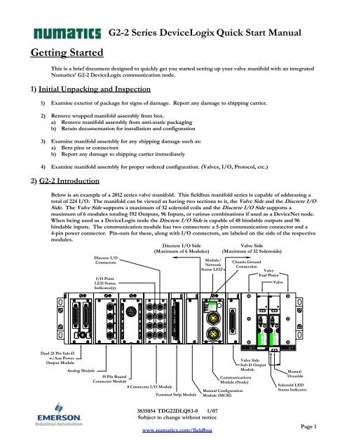
Below is an example of a 2012 series valve manifold. This fieldbus manifold series is capable of addressing a<br />
total of 224 I/O. The manifold can be viewed as having two sections to it, the Valve Si<strong>de</strong> and the Discrete I/O<br />
Si<strong>de</strong>. The Valve Si<strong>de</strong> supports a maximum of 32 solenoid coils and the Discrete I/O Si<strong>de</strong> supports a<br />
maximum of 6 modules totaling 192 Outputs, 96 Inputs, or various combinations if used as a DeviceNet no<strong>de</strong>.<br />
When being used as a DeviceLogix no<strong>de</strong> the Discrete I/O Si<strong>de</strong> is capable of 48 bindable outputs and 96<br />
bindable inputs. The communication module has two connectors: a 5-pin communication connector and a<br />
4-pin power connector. Pin-outs for these, along with I/O connectors, are labeled on the si<strong>de</strong> of the respective<br />
modules.<br />
Dual 25 Pin Sub-D<br />
w/Aux Power<br />
Output Module<br />
Discrete I/O<br />
Connectors<br />
I/O Point<br />
LED Status<br />
Indicator(s)<br />
Analog Module<br />
19 Pin Round<br />
Connector Module<br />
8 Connector I/O Module<br />
Discrete I/O Si<strong>de</strong><br />
(Maximum of 6 Modules)<br />
Terminal Strip Module<br />
3835054 TDG22DLQS3-0 1/07<br />
Subject to change without notice<br />
www.numatics.com/fieldbus<br />
Module/<br />
Network<br />
Status LED's<br />
NET STATUS<br />
MOD STATUS<br />
RUN/FORCE I/O<br />
FUSE 1<br />
+24V VLV/OUT<br />
FUSE 2<br />
+24V NODE/IN<br />
TM<br />
DeviceLogix<br />
Valve Si<strong>de</strong><br />
(Maximum of 32 Solenoids)<br />
Chassis Ground<br />
Connection<br />
Valve<br />
End Plates<br />
Valve<br />
Valve Si<strong>de</strong><br />
Sub-D Output<br />
Module<br />
Communications<br />
Module (No<strong>de</strong>)<br />
Manual Configuration<br />
Module (MCM)<br />
Manual<br />
Overri<strong>de</strong><br />
Solenoid LED<br />
Status Indicator<br />
Page 1
G2-2 Series DeviceLogix Quick Start Manual<br />
3) MCM - Manual Configuration Module (Optional)<br />
Rotary Switch<br />
(SW3)<br />
Rotary Switch<br />
(SW4)<br />
The MCM is the module that allows the user to manually set baud rate, MAC ID and other user <strong>de</strong>finable<br />
options, without the need for software configuration. If software configuration is preferred, this module is not<br />
necessary. The MCM consists of two DIP switch sets (SW1 and SW2) and two rotary switches (SW3 and SW4).<br />
MCM Module Part Numbers<br />
ON<br />
DIP Switch<br />
(SW2)<br />
1 2 3 4 5 6 7 8<br />
DIP Switch<br />
(SW1)<br />
All DIP switches shown in the "OFF" position<br />
ON<br />
1 2 3 4 5 6 7 8<br />
Description Part Number<br />
Complete Module 239-1384<br />
Replacement Board 256-684<br />
3835054 TDG22DLQS3-0 1/07<br />
Subject to change without notice<br />
www.numatics.com/fieldbus<br />
Page 2
MCM Settings<br />
DIP Switch Settings (SW1)<br />
Baud Rate:<br />
G2-2 Series DeviceLogix Quick Start Manual<br />
SW1-1 SW1-2 Kbaud<br />
Off* Off* 125*<br />
Off On 250<br />
On Off 500<br />
On On 500<br />
Autobaud:<br />
Switch Setting Description<br />
SW1-4 Off*<br />
Autobaud Enabled (baud rate configures automatically for 125Kbps,<br />
250 Kbps, and 500 Kbps)<br />
SW1-4 On<br />
Autobaud Disabled (set the baud rate manually either through switches or<br />
software)<br />
Manual or Software Configuration:<br />
Switch Setting Description<br />
SW1-5 Off MCM Disabled - Ignore MCM Settings (Software Configured)<br />
SW1-5 On* MCM Enabled - Use MCM Settings (Manually Configured)<br />
DIP Switch Settings (SW2) – No Function<br />
Rotary Switch Settings (SW3 and SW4)<br />
MAC ID (Network Address):<br />
Switch Description<br />
SW3 Sets the Ones Digits<br />
SW4 Sets the Tens Digits<br />
3835054 TDG22DLQS3-0 1/07<br />
Subject to change without notice<br />
www.numatics.com/fieldbus<br />
*Factory Default Settings<br />
Address is set to a <strong>de</strong>fault setting of 63 prior to shipment. Rotary switch<br />
settings over 63, <strong>de</strong>fault to 63<br />
DIP and rotary switch settings do not take effect until power is cycled<br />
(turned OFF and ON).<br />
Page 3
4) Self-Test Mo<strong>de</strong><br />
G2-2 Series DeviceLogix Quick Start Manual<br />
An internal diagnostic tool can also be enabled using the optional MCM module. This tool allows the user to<br />
confirm that all of the Inputs and Outputs on the manifold are fully functional without needing a network<br />
connection or controller. There are two test mo<strong>de</strong>s that the user can choose using SW2-8. The “Output” test<br />
mo<strong>de</strong> tests all the outputs by sequentially turning them ON one at a time. The “Input/Output” test mo<strong>de</strong><br />
tests the inputs by causing all of the outputs to toggle between even and odd values when any input is ma<strong>de</strong>.<br />
To use the Self-Test Mo<strong>de</strong>, the user must first set some initial conditions using the MCM module. Follow<br />
these steps to obtain the nee<strong>de</strong>d initial condition settings. Remember to remove power from the manifold<br />
before making changes to the MCM when setting these initial conditions.<br />
1) Disconnect power and air from the manifold!<br />
2) Record current MCM settings.<br />
3) Set the rotary switches to 99 (SW3 and SW4).<br />
4) Make sure that SW1-5, SW2-1, and SW2-7 are in the “ON” position.<br />
5) Select the <strong>de</strong>sired test mo<strong>de</strong> with SW2-8 (see table below)<br />
Switch Testing<br />
Setting<br />
Mo<strong>de</strong><br />
Description<br />
Output Off Sequentially turns all the outputs ON and OFF.<br />
SW2-8 Input/<br />
Output On<br />
Causes all of the odd outputs to come on and stay on until an<br />
input is ma<strong>de</strong>. When an input is ma<strong>de</strong>, the outputs will toggle to<br />
the even outputs.<br />
6) Make sure that all of the other switches are in the “OFF” position.<br />
The initial conditions are now set. To enable the Self-Test Mo<strong>de</strong>, apply power to the manifold and make the<br />
following changes while the module status LED is blinking (within 5 to 10 seconds of power up):<br />
1) Set SW2-6 to the “ON” position.<br />
2) Set SW2-7 to the “OFF” position.<br />
Once Self-Test Mo<strong>de</strong> is enabled, the module status LED will flash red/green until Self-Test Mo<strong>de</strong> is<br />
terminated by removing power to the unit. Remember to return the MCM settings to their original settings to<br />
return the communication no<strong>de</strong> to normal operation.<br />
!<br />
Air should be disconnected to the manifold when attempting to run the<br />
Self-Test Mo<strong>de</strong> to prevent unwanted motion.<br />
Communication lines should be disconnected before attempting to run the<br />
Self-Test Mo<strong>de</strong>.<br />
3835054 TDG22DLQS3-0 1/07<br />
Subject to change without notice<br />
www.numatics.com/fieldbus<br />
Page 4
5) I/O Mapping Example<br />
Example:<br />
Assumed Settings<br />
- Single Z-Boards TM used with single solenoid<br />
valves<br />
- Double Z-Boards TM used with double solenoid<br />
valves<br />
For simplicity, two mapping formats are given to<br />
match appropriate software tools (i.e. DeviceLogix is<br />
for the logic editor function within RSNetworx TM for<br />
DeviceNet).<br />
Discrete I/O Configuration<br />
Pos<br />
Module Type<br />
No.<br />
Part No.<br />
Rx Tx<br />
Bytes<br />
1 MCM 239-1384 -- --<br />
2<br />
8O Sourcing<br />
(PNP)<br />
239-1315 1 1<br />
3<br />
16O Sourcing<br />
(PNP)<br />
239-1319 1 2<br />
4<br />
4I Sinking<br />
(NPN)<br />
239-1304 1 0<br />
5<br />
8I Sinking<br />
(NPN)<br />
239-1308 1 0<br />
Manifold I/O Configuration<br />
Outputs and Mapping Location<br />
-Valve Outputs = 12<br />
-Allocated Unused<br />
Valve Outputs = 20<br />
-Discrete Outputs = 24<br />
Total Outputs = 56<br />
G2-2 Series DeviceLogix Quick Start Manual<br />
DeviceNet DeviceLogix<br />
Byte 0, Bits 0-7<br />
Byte 1, Bits 0-3<br />
Byte 1, Bits 4-7<br />
Bytes 2 - 3, Bits<br />
0-7<br />
Bytes 4,5 & 6<br />
Bits 0-7<br />
Bits 0-11<br />
Bits 12-31<br />
Bits 32-55<br />
Inputs and Mapping Location<br />
DeviceNet DeviceLogix<br />
-Discrete Inputs = 12<br />
-Allocated and<br />
Reserved Inputs = 4<br />
Total Inputs = 16<br />
Byte 6, Bits 0-3<br />
Byte 7, Bits 0-7<br />
Bits0-3<br />
and 8-15<br />
Byte 6, Bits 4-7 Bits 4-7<br />
When the 12 End<br />
Solenoid is<br />
energized, the 2 port<br />
is pressurized.<br />
3835054 TDG22DLQS3-0 1/07<br />
Subject to change without notice<br />
www.numatics.com/fieldbus<br />
When the 14 End<br />
Solenoid is<br />
energized, the 4 port<br />
is pressurized.<br />
Page 5
G2-2 Series DeviceLogix Quick Start Manual<br />
DeviceLogix (Logic Editor) I/O Mapping Table Example Continued<br />
Discrete Output Table<br />
Output 0 Output 1 Output 2 Output 3 Output 4 Output 5 Output 6 Output 7<br />
Valve Coil No. 1 Valve Coil No. 2 Valve Coil No. 3 Valve Coil No. 4 Valve Coil No. 5 Valve Coil No. 6 Valve Coil No. 7 Valve Coil No. 8<br />
Output 8 Output 9 Output 10 Output 11 Output 12 Output 13 Output 14 Output 15<br />
Valve Coil No. 9<br />
Output 16<br />
Valve Coil No. 10<br />
Output 17<br />
Valve Coil No. 11<br />
Output 18<br />
Valve Coil No. 12<br />
Output 19<br />
Allocated &<br />
Reserved<br />
Output 20<br />
Allocated &<br />
Reserved<br />
Output 21<br />
Allocated &<br />
Reserved<br />
Output 22<br />
Allocated &<br />
Reserved<br />
Output 23<br />
Allocated &<br />
Allocated &<br />
Allocated &<br />
Allocated &<br />
Allocated &<br />
Allocated &<br />
Allocated &<br />
Allocated &<br />
Reserved<br />
Reserved<br />
Reserved<br />
Reserved<br />
Reserved<br />
Reserved<br />
Reserved<br />
Reserved<br />
Output 24 Output 25 Output 26 Output 27 Output 28 Output 29 Output 30 Output 31<br />
Allocated &<br />
Allocated &<br />
Allocated &<br />
Allocated &<br />
Allocated &<br />
Allocated &<br />
Allocated &<br />
Allocated &<br />
Reserved<br />
Output 32<br />
Reserved<br />
Output 33<br />
Reserved<br />
Output 34<br />
Reserved<br />
Output 35<br />
Reserved<br />
Output 36<br />
Reserved<br />
Output 37<br />
Reserved<br />
Output 38<br />
Reserved<br />
Output 39<br />
Discrete<br />
Output No. 0<br />
Discrete<br />
Output No. 1<br />
Discrete<br />
Output No. 2<br />
Discrete<br />
Output No. 3<br />
Discrete<br />
Output No. 4<br />
3835054 TDG22DLQS3-0 1/07<br />
Subject to change without notice<br />
www.numatics.com/fieldbus<br />
Discrete<br />
Output No. 5<br />
Discrete<br />
Output No. 6<br />
Discrete<br />
Output No. 7<br />
Output 40 Output 41 Output 42 Output 43 Output 44 Output 45 Output 46 Output 47<br />
Discrete<br />
Output No. 0<br />
Discrete<br />
Output No. 1<br />
Discrete<br />
Output No. 2<br />
Discrete<br />
Output No. 3<br />
Discrete<br />
Output No. 4<br />
Discrete<br />
Output No. 5<br />
Discrete<br />
Output No. 6<br />
Discrete<br />
Output No. 7<br />
Output 48 Output 49 Output 50 Output 51 Output 52 Output 53 Output 54 Output 55<br />
Discrete<br />
Output No. 8<br />
Discrete<br />
Output No. 9<br />
Discrete<br />
Output No. 10<br />
Discrete<br />
Output No. 11<br />
Discrete<br />
Output No. 12<br />
Discrete<br />
Output No. 13<br />
Discrete<br />
Output No. 14<br />
Discrete<br />
Output No. 15<br />
Discrete Input Table<br />
Input 0 Input 1 Input 2 Input 3 Input 4 Input 5 Input 6 Input 7<br />
Discrete<br />
Input No. 0<br />
Discrete<br />
Input No. 1<br />
Discrete<br />
Input No. 2<br />
Discrete<br />
Input No. 3<br />
Allocated &<br />
Reserved<br />
Allocated &<br />
Reserved<br />
Allocated &<br />
Reserved<br />
Allocated &<br />
Reserved<br />
Input 8 Input 9 Input 10 Input 11 Input 12 Input 13 Input 14 Input 15<br />
Discrete<br />
Input No. 0<br />
Discrete<br />
Input No. 1<br />
Discrete<br />
Input No. 2<br />
Discrete<br />
Input No. 3<br />
Discrete<br />
Input No. 4<br />
Network Output Table<br />
Discrete<br />
Input No. 5<br />
Discrete<br />
Input No. 6<br />
Discrete<br />
Input No. 7<br />
Output 0 Output 1 Output 2 Output 3 Output 4 Output 5 Output 6 Output 7<br />
Network<br />
Output No. 0<br />
Network<br />
Output No. 1<br />
Network<br />
Output No. 2<br />
Network<br />
Output No. 3<br />
Network<br />
Output No. 4<br />
Network Input Table<br />
Network<br />
Output No. 5<br />
Network<br />
Output No. 6<br />
Network<br />
Output No. 7<br />
Input 0 Output 1 Input 2 Input 3 Input 4 Input 5 Input 6 Input 7<br />
Network<br />
Input No. 0<br />
Network<br />
Input No. 1<br />
Network<br />
Input No. 2<br />
Network<br />
Input No. 3<br />
Network<br />
Input No. 4<br />
Fault Input Table (Status Input Bits)<br />
Network<br />
Input No. 5<br />
Network<br />
Input No. 6<br />
Network<br />
Input No. 7<br />
Fault Input 0 Fault Input 1 Fault Input 2 Fault Input 3 Fault Input 4 Fault Input 5 Fault Input 6 Fault Input 7<br />
Coil No. 1 Status Coil No. 2 Status Coil No. 3 Status Coil No. 4 Status Coil No. 5 Status Coil No. 6 Status Coil No. 7 Status Coil No. 8 Status<br />
Fault Input 8 Fault Input 9 Fault Input 10 Fault Input 11 Fault Input 12 Fault Input 13 Fault Input 14 Fault Input 15<br />
Coil No. 9 Status Coil No. 10 Status Coil No. 11 Status Coil No. 12 Status Coil No. 13 Status Coil No. 14 Status Coil No. 15 Status Coil No. 16 Status<br />
Fault Input 16 Fault Input 17 Fault Input 18 Fault Input 19 Fault Input 20 Fault Input 21 Fault Input 22 Fault Input 23<br />
Coil No. 17 Status Coil No. 18 Status Coil No. 19 Status Coil No. 20 Status Coil No. 21 Status Coil No. 22 Status Coil No. 23 Status Coil No. 24 Status<br />
Fault Input 24 Fault Input 25 Fault Input 26 Fault Input 27 Fault Input 28 Fault Input 29 Fault Input 30 Fault Input 31<br />
Coil No. 25 Status Coil No. 26 Status Coil No. 27 Status Coil No. 28 Status Coil No. 29 Status Coil No. 30 Status Coil No. 31 Status Coil No. 32 Status<br />
The “Network Outputs” are data coming from the communications no<strong>de</strong> and<br />
reported to the Master Input Data file. The “Network Inputs” are data coming<br />
from the Master Output Data file to the communications no<strong>de</strong>. They are used for<br />
handshaking communication between master (scanner) and slave (no<strong>de</strong>) if<br />
DeviceLogix is used on a DeviceNet network.<br />
Page 6
G2-2 Series DeviceLogix Quick Start Manual<br />
DeviceNet I/O Mapping Table Example Continued<br />
BYTE Bit 7 Bit 6 Bit 5<br />
Output Table<br />
Bit 4 Bit 3 Bit 2 Bit 1 Bit 0<br />
0<br />
1<br />
2<br />
3<br />
4<br />
5<br />
6<br />
7<br />
Valve Coil<br />
No. 8<br />
Allocated &<br />
Reserved<br />
Allocated &<br />
Reserved<br />
Allocated &<br />
Reserved<br />
Discrete<br />
Output No. 7<br />
Discrete<br />
Output No. 7<br />
Discrete<br />
Output No. 15<br />
Network<br />
Input No. 7<br />
Valve Coil<br />
No. 7<br />
Allocated &<br />
Reserved<br />
Allocated &<br />
Reserved<br />
Allocated &<br />
Reserved<br />
Discrete<br />
Output No. 6<br />
Discrete<br />
Output No. 6<br />
Discrete<br />
Output No. 14<br />
Network<br />
Input No. 6<br />
Valve Coil<br />
No. 6<br />
Allocated &<br />
Reserved<br />
Allocated &<br />
Reserved<br />
Allocated &<br />
Reserved<br />
Discrete<br />
Output No. 5<br />
Discrete<br />
Output No. 5<br />
Discrete<br />
Output No. 13<br />
Network<br />
Input No. 5<br />
Valve Coil<br />
No. 5<br />
Allocated &<br />
Reserved<br />
Allocated &<br />
Reserved<br />
Allocated &<br />
Reserved<br />
Discrete<br />
Output No. 4<br />
Discrete<br />
Output No. 4<br />
Discrete<br />
Output No. 12<br />
Network<br />
Input No. 4<br />
Valve Coil<br />
No. 4<br />
Valve Coil<br />
No. 12<br />
Allocated &<br />
Reserved<br />
Allocated &<br />
Reserved<br />
Discrete<br />
Output No. 3<br />
Discrete<br />
Output No. 3<br />
Discrete<br />
Output No. 11<br />
Network<br />
Input No. 3<br />
3835054 TDG22DLQS3-0 1/07<br />
Subject to change without notice<br />
www.numatics.com/fieldbus<br />
Valve Coil<br />
No. 3<br />
Valve Coil<br />
No. 11<br />
Allocated &<br />
Reserved<br />
Allocated &<br />
Reserved<br />
Discrete<br />
Output No. 2<br />
Discrete<br />
Output No. 2<br />
Discrete<br />
Output No. 10<br />
Network<br />
Input No. 2<br />
Valve Coil<br />
No. 2<br />
Valve Coil<br />
No. 10<br />
Allocated &<br />
Reserved<br />
Allocated &<br />
Reserved<br />
Discrete<br />
Output No. 1<br />
Discrete<br />
Output No. 1<br />
Discrete<br />
Output No. 9<br />
Network<br />
Input No. 1<br />
Valve Coil<br />
No. 1<br />
Valve Coil<br />
No. 9<br />
Allocated &<br />
Reserved<br />
Allocated &<br />
Reserved<br />
Discrete<br />
Output No. 0<br />
Discrete<br />
Output No. 0<br />
Discrete<br />
Output No. 8<br />
Network<br />
Input No. 0<br />
BYTE Bit 7 Bit 6 Bit 5<br />
Input Table<br />
Bit 4 Bit 3 Bit 2 Bit 1 Bit 0<br />
0<br />
1<br />
2<br />
3<br />
4<br />
5<br />
6<br />
7<br />
8<br />
Coil No. 8<br />
Status<br />
Coil No. 16<br />
Status<br />
Coil No. 24<br />
Status<br />
Coil No. 32<br />
Status<br />
Allocated &<br />
Reserved<br />
Allocated &<br />
Reserved<br />
Allocated &<br />
Reserved<br />
Discrete<br />
Input No. 7<br />
Network<br />
Output No. 7<br />
Coil No. 7<br />
Status<br />
Coil No. 15<br />
Status<br />
Coil No. 23<br />
Status<br />
Coil No. 31<br />
Status<br />
Allocated &<br />
Reserved<br />
Allocated &<br />
Reserved<br />
Allocated &<br />
Reserved<br />
Discrete<br />
Input No. 6<br />
Network<br />
Output No. 6<br />
Coil No. 6<br />
Status<br />
Coil No. 14<br />
Status<br />
Coil No. 22<br />
Status<br />
Coil No. 30<br />
Status<br />
Allocated &<br />
Reserved<br />
Allocated &<br />
Reserved<br />
Allocated &<br />
Reserved<br />
Discrete<br />
Input No. 5<br />
Network<br />
Output No. 5<br />
Coil No. 5<br />
Status<br />
Coil No. 13<br />
Status<br />
Coil No. 21<br />
Status<br />
Coil No. 29<br />
Status<br />
Allocated &<br />
Reserved<br />
Allocated &<br />
Reserved<br />
Allocated &<br />
Reserved<br />
Discrete<br />
Input No. 4<br />
Network<br />
Output No. 4<br />
Coil No. 4<br />
Status<br />
Coil No. 12<br />
Status<br />
Coil No. 20<br />
Status<br />
Coil No. 28<br />
Status<br />
Allocated &<br />
Reserved<br />
Status for<br />
Discrete<br />
Outputs<br />
No. 12-15<br />
Discrete<br />
Input No. 3<br />
Discrete<br />
Input No. 3<br />
Network<br />
Output No. 3<br />
Coil No. 3<br />
Status<br />
Coil No. 11<br />
Status<br />
Coil No. 19<br />
Status<br />
Coil No. 27<br />
Status<br />
Allocated &<br />
Reserved<br />
Status for<br />
Discrete<br />
Outputs<br />
No. 8-11<br />
Discrete<br />
Input No. 2<br />
Discrete<br />
Input No. 2<br />
Network<br />
Output No. 2<br />
Coil No. 2<br />
Status<br />
Coil No. 10<br />
Status<br />
Coil No. 18<br />
Status<br />
Coil No. 26<br />
Status<br />
Status for<br />
Discrete<br />
Outputs<br />
No. 4-7<br />
Status for<br />
Discrete<br />
Outputs<br />
No. 4-7<br />
Discrete<br />
Input No. 1<br />
Discrete<br />
Input No. 1<br />
Network<br />
Output No. 1<br />
Coil No. 1<br />
Status<br />
Coil No. 9<br />
Status<br />
Coil No. 17<br />
Status<br />
Coil No. 25<br />
Status<br />
Status for<br />
Discrete<br />
Outputs<br />
No. 0-3<br />
Status for<br />
Discrete<br />
Outputs<br />
No. 0-3<br />
Discrete<br />
Input No. 0<br />
Discrete<br />
Input No. 0<br />
Network<br />
Output No. 0<br />
The “Network Outputs” are data coming from the communications no<strong>de</strong> and<br />
reported to the Master Input Data file. The “Network Inputs” are data coming<br />
from the Master Output Data file to the communications no<strong>de</strong>. They are used for<br />
handshaking communication between master (scanner) and slave (no<strong>de</strong>) if<br />
DeviceLogix is used on a DeviceNet network.<br />
Page 7
G2-2 Series DeviceLogix Quick Start Manual<br />
6) Output Short Circuit Protection (Status Input Bits)<br />
Status Input Bits report the integrity of the load being driven by the output driver. They must be mapped to the<br />
scanner as part of the Input Size Value. Please refer to the table below for Status Input Bit action during fault<br />
condition:<br />
Output Type Output State Fault Condition Status Bit<br />
Valve Solenoid Coil Driver or<br />
Sinking (NPN)<br />
Discrete Outputs<br />
ON<br />
OFF<br />
No Fault<br />
Fault - Short Circuit, Over Temp/Over Current<br />
No Fault<br />
Fault - Open Load<br />
0<br />
1<br />
0<br />
1<br />
Sourcing (PNP)<br />
Discrete Outputs<br />
ON<br />
No Fault<br />
Fault - Short Circuit, Over Temp/Over Current<br />
0<br />
1<br />
7) Ground Wiring<br />
All <strong>Numatics</strong> Inc. communication no<strong>de</strong>s should be groun<strong>de</strong>d during the installation process. These<br />
grounding gui<strong>de</strong>lines can be found in National Electrical co<strong>de</strong> IEC 60204-1 or EN 60204-1. There also is a,<br />
“ATTENTION: CONNECT TO EARTH GROUND FOR PROPER GROUNDING OF UNIT”, label<br />
attached to the chassis ground connection point on the G2-2 series communication no<strong>de</strong> housing. This label<br />
also points out where the grounding gui<strong>de</strong>lines can be found.<br />
!<br />
NET STATUS<br />
MOD STATUS<br />
FUSE 1<br />
+24V VLV/OUT<br />
FUSE 2<br />
+24V NODE/IN<br />
TM<br />
Proper grounding will alleviate and prevent many intermittent problems<br />
with network communication.<br />
When grounding to a machine frame, please ensure that the machine frame<br />
itself is already properly groun<strong>de</strong>d.<br />
Better grounding can be achieved when larger diameter (lower gauge) wire<br />
is used.<br />
3835054 TDG22DLQS3-0 1/07<br />
Subject to change without notice<br />
www.numatics.com/fieldbus<br />
ATTENTION:<br />
CONNECT TO EARTH<br />
GROUND FOR PROPER<br />
GROUNDING OF UNIT<br />
Reference National<br />
Electrical co<strong>de</strong><br />
IEC 60204-1 or EN 60204-1<br />
for grounding gui<strong>de</strong>lines<br />
Page 8
G2-2 Series DeviceLogix Quick Start Manual<br />
8) Communication Module Connector Pin-Outs<br />
DeviceNet Communication Connector Pin-Out<br />
Pin No. Function Description<br />
1 Shield Cable shield<br />
2 V+ Bus Power, 11-25VDC<br />
3 V- Bus Power, Common<br />
4 CAN_H Controller Area Network High, Communication Line<br />
5 CAN_L Controller Area Network Low, Communication Line<br />
Auxiliary Power Connector Pin-Out<br />
!<br />
Standard<br />
Pin No.<br />
COM<br />
AUX<br />
Cenelec<br />
Pin No.<br />
Function Description<br />
1 1<br />
+24VDC<br />
(Valves and Outputs)<br />
Voltage Used to Power Outputs<br />
(Valve Coils and Discrete Outputs)<br />
2 3 Earth Ground Protective Earth (Case Ground)<br />
3 4 0VDC Common 0VDC Common, for Valves, I/O, and No<strong>de</strong> Power<br />
4 2<br />
+24VDC<br />
(No<strong>de</strong> and Inputs)<br />
Voltage Used to Power Discrete Inputs and No<strong>de</strong><br />
Electronics<br />
DeviceLogix<br />
4 3<br />
2<br />
5 1<br />
3<br />
4<br />
2<br />
1<br />
TM<br />
MALE<br />
MALE<br />
COM<br />
AUX<br />
DeviceLogix TM<br />
4 3<br />
DeviceLogix TM<br />
4 3<br />
5 MALE<br />
COM 2 MALE<br />
1 2<br />
5 1<br />
3<br />
4<br />
Maximum current capacity on the 0VDC common pin of auxiliary power<br />
connector is 8 Amps. The combined draw of the +24VDC Valves & Outputs<br />
and +24VDC No<strong>de</strong> & Inputs pins cannot exceed 8 Amps, at any given<br />
moment in time.<br />
The auxiliary power No<strong>de</strong> & Inputs pin supplies power to the no<strong>de</strong><br />
electronics. This pin must be powered at all times for communication no<strong>de</strong><br />
to be functional.<br />
The Cenelec power connector has a black insert and the standard power<br />
connector has a yellow insert.<br />
3835054 TDG22DLQS3-0 1/07<br />
Subject to change without notice<br />
www.numatics.com/fieldbus<br />
2<br />
1<br />
MALE<br />
AUX<br />
1<br />
2<br />
3<br />
4<br />
MALE<br />
Page 9
9) LED Functions<br />
G2-2 Series DeviceLogix Quick Start Manual<br />
Upon power up, the LEDs indicate the status of the unit. There are seven LEDs on the G2-2 DeviceLogix<br />
no<strong>de</strong>; Network Status, Module Status, Run/Force I/O, two for internal fuse integrity, and two for Aux. Power<br />
status.<br />
NET STATUS<br />
MOD STATUS<br />
FUSE 1<br />
+24V VLV/OUT<br />
FUSE 2<br />
+24V NODE/IN<br />
TM<br />
LED Name Color Status Description<br />
Stand Alone – Network cable is not connected to no<strong>de</strong>. Normal<br />
Operation<br />
Off OFF<br />
Networked - Device is not on-line; Bus power not applied; Physical<br />
problem with network; Improper baud rate.<br />
NET STATUS<br />
(Network Status)<br />
Green<br />
ON<br />
FLASHING<br />
Normal operation. Device is on-line and has established a<br />
connection.<br />
Device is on-line but has no established connections.<br />
The <strong>de</strong>vice has <strong>de</strong>tected a bus error that has ren<strong>de</strong>red it incapable<br />
ON of communicating on the network; Duplicate MAC ID; “Bus Off”<br />
Red<br />
condition; Physical problem with network.<br />
FLASHING<br />
Communication failure – one or more I/O connections have timed<br />
out.<br />
OFF Critical hardware fault. Microprocessor is not running.<br />
ON Normal operation. The <strong>de</strong>vice is operating properly.<br />
MOD STATUS<br />
(Module Status)<br />
Green<br />
FLASHING<br />
Stand Alone – If logic is disabled and communication status<br />
overri<strong>de</strong> is disabled then network power is absent.<br />
Networked - Network power is absent.<br />
Green Red FLASHING Module is in self-test mo<strong>de</strong>.<br />
RUN / FORCE<br />
I/O<br />
Yellow<br />
OFF<br />
ON<br />
FLASHING<br />
Logic is disabled<br />
Logic is enabled<br />
Logic is enabled and local forces are applied<br />
FUSE 1 Red<br />
OFF<br />
ON<br />
Internal fuse F1 is OK (valid only when power is applied to<br />
+24V VLV / OUT pin on Aux. Power connector).<br />
Internal fuse F1 is open; No power is internally provi<strong>de</strong>d to valves or<br />
outputs. Communication NOT affected.<br />
+24V VLV/OUT Green<br />
OFF<br />
No DC Power present at +24V VLV / OUT pin on Aux. Power<br />
connector.<br />
ON DC Power applied to +24V VLV / OUT pin on Aux. Power Connector.<br />
FUSE 2 Red<br />
OFF<br />
ON<br />
Internal fuse F2 is OK (valid only when power is applied to<br />
+24V NODE / IN pin on Aux. Power connector.<br />
Internal fuse F2 is open; No power is internally provi<strong>de</strong>d to no<strong>de</strong><br />
electronics or inputs. Communication No<strong>de</strong> will not function.<br />
+24V NODE/IN Green<br />
OFF<br />
No DC Power present at +24V NODE / IN pin on Aux. Power<br />
connector.<br />
ON DC Power applied to+24V NODE / IN pin on Aux. Power connector.<br />
3835054 TDG22DLQS3-0 1/07<br />
Subject to change without notice<br />
www.numatics.com/fieldbus<br />
NET STATUS<br />
MOD STATUS<br />
FUSE 1<br />
+24V VLV/OUT<br />
FUSE 2<br />
+24V NODE/IN<br />
TM<br />
Page 10
10) Function Block<br />
G2-2 Series DeviceLogix Quick Start Manual<br />
<strong>Numatics</strong> DeviceLogix no<strong>de</strong>s integrates all four types of function blocks; Boolean, Bistable, Counter and<br />
Timers. A maximum of 72 function blocks, in any combination, can be used to <strong>de</strong>velop a program sequence.<br />
Boolean Bistable Counter Timer<br />
AND SRL (SR-Latch) UPC (up counter) OND (on <strong>de</strong>lay timer)<br />
OR RSL (RS-Latch) UPD (up and down counter) OFD (off <strong>de</strong>lay timer)<br />
XOR (exclusive OR) PUL (pulse timer)<br />
NOT<br />
NAND (negative output AND)<br />
NOR (negative output OR)<br />
XNO (negative output exclusive OR)<br />
11) Lad<strong>de</strong>r Components<br />
<strong>Numatics</strong> DeviceNet/DeviceLogix no<strong>de</strong>s also have the ability to be programmed using the lad<strong>de</strong>r editor in<br />
RSNetworx. The lad<strong>de</strong>r editor still integrates Latches, Counters and Timers, but instead of Boolean logic<br />
blocks, it uses lad<strong>de</strong>r rungs and branches. Also, instead of a maximum function block number, there is a<br />
maximum amount of memory available for use. A percentage will appear in the message window below the<br />
lad<strong>de</strong>r editor window indicating how much memory the user still is allowed.<br />
Latch Counter Timer<br />
SRL (SR-Latch) UPC (up counter) OND (on <strong>de</strong>lay timer)<br />
RSL (RS-Latch) UPD (up and down counter) OFD (off <strong>de</strong>lay timer)<br />
PUL (pulse timer)<br />
3835054 TDG22DLQS3-0 1/07<br />
Subject to change without notice<br />
www.numatics.com/fieldbus<br />
Page 11
G2-2 Series DeviceLogix Quick Start Manual<br />
12) Stand-Alone Versus Networked Functionality<br />
The <strong>Numatics</strong> DeviceLogix communication no<strong>de</strong> can be used as a stand-alone programmable <strong>de</strong>vice or as<br />
part of a DeviceNet network. Using the RSNetworx TM for DeviceNet software, different settings must be<br />
enabled or disabled to configure these options.<br />
Stand-Alone Settings<br />
To configure your <strong>Numatics</strong> DeviceLogix manifold to function as a stand-alone no<strong>de</strong>, enable both the<br />
“Network Status Overri<strong>de</strong>” and “Comm. Status Overri<strong>de</strong>”.<br />
Enabled<br />
Enabled<br />
9 Bytes<br />
8 Bytes<br />
239-1290 / 1291<br />
4 Bytes<br />
4 Bytes<br />
239-1384: Rx – 0, Tx – 0<br />
239-1315: Rx – 1, Tx – 1<br />
239-1319: Rx – 1, Tx – 2<br />
239-1304: Rx – 1, Tx – 0<br />
239-1308: Rx – 1, Tx – 0<br />
No Default<br />
Enabled<br />
Enabled<br />
3835054 TDG22DLQS3-0 1/07<br />
Subject to change without notice<br />
www.numatics.com/fieldbus<br />
Page 12
Network/Communication Settings<br />
G2-2 Series DeviceLogix Quick Start Manual<br />
The following table <strong>de</strong>scribes the behaviors that occur when the Network Status Overri<strong>de</strong> and Communication<br />
Status Overri<strong>de</strong> attributes are disabled. The user may have the DeviceLogix no<strong>de</strong> begin local logic mo<strong>de</strong> in<br />
cases where a network signal is lost. This is configured by enabling “Comm Status Overri<strong>de</strong>” and “Network<br />
Status Overri<strong>de</strong>”.<br />
Network/Communication Settings DISABLED Chart<br />
Attribute<br />
Network Status<br />
Overri<strong>de</strong><br />
(Disabled)<br />
Communication<br />
Status Overri<strong>de</strong><br />
(Disabled)<br />
!<br />
Network<br />
LED Status<br />
Off<br />
Event Behavior<br />
The manifold is powered up<br />
without a network connection<br />
Red Duplicate Mac ID error<br />
Flashing<br />
Red<br />
Green<br />
Flashing<br />
Green<br />
Flashing<br />
Red<br />
The manifold has lost the I/O<br />
connection.<br />
An Idle is received<br />
(still on network, but the PLC is<br />
not sending data to it. For<br />
example, the key on the PLC is<br />
turned into program mo<strong>de</strong>)<br />
Communications not<br />
established (module not online)<br />
- OR -<br />
The manifold is online but there<br />
is no data being sent between a<br />
master and itself<br />
The manifold has lost the I/O<br />
connection.<br />
3835054 TDG22DLQS3-0 1/07<br />
Subject to change without notice<br />
www.numatics.com/fieldbus<br />
The manifold is put into an<br />
inoperable state and all<br />
Outputs remain off.<br />
The manifold output values are<br />
updated based on the Output<br />
Fault Action and Fault Value<br />
attributes.<br />
The manifold output values are<br />
updated based on the Output<br />
Idle Action and Idle Value<br />
attributes.<br />
The manifold outputs remain<br />
in the available state until an<br />
I/O connection is established.<br />
The manifold output values are<br />
updated based on the Output<br />
Fault Action and Fault Value<br />
attributes.<br />
The manifold can ALWAYS be controlled by local logic when the Network<br />
Status and Communication Status overri<strong>de</strong>s are ENABLED.<br />
Page 13
13) G2-2 DeviceLogix Features<br />
14) Factory Default Settings<br />
G2-2 Series DeviceLogix Quick Start Manual<br />
Features Description<br />
DeviceNet Spec. Supported Designed to DeviceNet Specification Revision 2.0<br />
Bus Topology Straight with restricted drops<br />
Baud Rates Supported 125Kbps, 250 Kbps and 500 Kbps and Autobaud<br />
Duplicate address <strong>de</strong>tection<br />
If duplicate address <strong>de</strong>tected on power up, duplicates will not<br />
progress to run mo<strong>de</strong><br />
Error Correction Yes, if error <strong>de</strong>tected, sen<strong>de</strong>r is requested to repeat the message<br />
Address Setting Via Software or optional Manual Configuration Module (MCM)<br />
Termination Resistor A 121 ohms, 1%, ¼ Watt resistor is required at each end of the<br />
(external)<br />
trunk line. Not necessary for stand alone applications.<br />
ADR support<br />
Auto-Device Replacement is supported when the MCM is<br />
disabled or not present. Program sequences are also saved.<br />
Function Blocks Maximum of 72 function blocks supported<br />
Connection Types Supported Polled, Cyclic, Change of State (COS) or Combinations<br />
Timers Default of 10 millisecond time base only! Regardless of setting.<br />
Unless otherwise requested, all standard G2-2 Series DeviceLogix manifolds ship with specific factory <strong>de</strong>fault<br />
settings. Below is a list of the factory <strong>de</strong>fault settings:<br />
15) Technical Support<br />
Description Default Settings<br />
No<strong>de</strong> Address 63<br />
Baud Rate Autobaud Enabled<br />
Input Module Power Jumper<br />
Output Module Power Jumper<br />
PU<br />
(Input sensor power supplied by<br />
+24VDC No<strong>de</strong> and Inputs pin on the Aux. power connector)<br />
SP<br />
(Output module power supplied by<br />
+24VDC Valves and Outputs pin on the Aux. power connector)<br />
Communication Status Overri<strong>de</strong> Enabled<br />
Configured for<br />
Network Status Overri<strong>de</strong> Enabled<br />
stand alone applications<br />
Valve Si<strong>de</strong> Output Bytes<br />
5/5 (4/4 for valve outputs & valve output status bits;<br />
1/1 for network I/O) Bytes<br />
Discrete I/O Si<strong>de</strong> - I/O Bytes Self-Configuring based on the I/O modules installed.<br />
For technical support, contact your local <strong>Numatics</strong> distributor. If further information is required,<br />
please call <strong>Numatics</strong> Inc. at (248) 887-4111 and ask for Technical Support.<br />
Issues relating to network set-up, PLC programming, sequencing, software related functions, etc…<br />
should be handled with the appropriate product vendor.<br />
Information on <strong>de</strong>vice files, technical manuals, local distributors, and other <strong>Numatics</strong>, Inc. products<br />
and support issues can be found on the <strong>Numatics</strong>, Inc’s. WEB site at www.numatics.com<br />
3835054 TDG22DLQS3-0 1/07<br />
Subject to change without notice<br />
www.numatics.com/fieldbus<br />
Page 14
Pour commencer<br />
<strong>Gui<strong>de</strong></strong> <strong>de</strong> <strong>Démarrage</strong> Rapi<strong>de</strong><br />
<strong>Série</strong> 2-2 - DeviceLogix<br />
Ce document décrit le démarrage rapi<strong>de</strong> <strong>de</strong> votre îlot <strong>de</strong> distribution à nœud <strong>de</strong> communication DeviceLogix<br />
série G2-2 intégré.<br />
1) Déballage et inspection<br />
1) Inspectez l'emballage extérieur pour détecter tout dommage. Tout dommage constaté doit être signalé au<br />
transporteur.<br />
2) Retirez l'ensemble <strong>de</strong> l'îlot <strong>de</strong> son carton.<br />
a) Sortez l'ensemble <strong>de</strong> son emballage anti-statique.<br />
b) Conservez la documentation portant sur l'installation et la configuration.<br />
3) Inspectez l'ensemble <strong>de</strong> l'îlot pour détecter tout dommage <strong>de</strong> transport tel que:<br />
a) Broches ou connecteurs déformés<br />
b) Tout dommage constaté doit être immédiatement signalé au transporteur.<br />
4) Vérifiez que la configuration <strong>de</strong> l'ensemble <strong>de</strong> l'îlot livré correspond à votre comman<strong>de</strong>. (distributeurs, E/S,<br />
protocole, …).<br />
2) Introduction à la série G2-2<br />
Ci-<strong>de</strong>ssous un exemple représentant l'ensemble d'un îlot <strong>de</strong> distributeurs <strong>de</strong> la série 2012. Cette série d'îlots à<br />
bus <strong>de</strong> terrain est capable d'adresser un total <strong>de</strong> 224 E/S. L'îlot peut être considéré comme ayant <strong>de</strong>ux<br />
parties: la partie Composants pneumatiques et la partie Composants électroniques. La partie Composants<br />
pneumatiques supporte un maximum <strong>de</strong> 32 bobines et la partie Composants électroniques supporte un<br />
maximum <strong>de</strong> 6 modules, donc un total <strong>de</strong> 192 sorties, 96 entrées ou <strong>de</strong> différentes combinaisons <strong>de</strong> celles-ci si<br />
utilisée en tant que nœud DeviceNet. Si la partie Composants électroniques est utilisée comme nœud<br />
DeviceLogix, sa capacité s'élève à 48 sorties et 96 entrées connectables. Le module <strong>de</strong> communication est<br />
équipé <strong>de</strong> <strong>de</strong>ux connecteurs : un connecteur <strong>de</strong> communication à 5 broches et un connecteur d'alimentation à<br />
4 broches. L'affectation <strong>de</strong>s broches ainsi que les connecteurs E/S sont repérés sur la face latérale <strong>de</strong> chaque<br />
module.<br />
Dual 25 Pin Sub-D<br />
w/Aux Power<br />
Output Module<br />
Discrete I/O<br />
Connectors<br />
I/O Point<br />
LED Status<br />
Indicator(s)<br />
Analog Module<br />
19 Pin Round<br />
Connector Module<br />
8 Connector I/O Module<br />
Discrete I/O Si<strong>de</strong><br />
(Maximum of 6 Modules)<br />
Terminal Strip Module<br />
Module/<br />
Network<br />
Status LED's<br />
NET STATUS<br />
MOD STATUS<br />
RUN/FORCE I/O<br />
FUSE 1<br />
+24V VLV/OUT<br />
FUSE 2<br />
+24V NODE/IN<br />
TM<br />
DeviceLogix<br />
3835054 TDG22DLQS3-0 1/07<br />
Sous réserve <strong>de</strong> modification sans avis préalable<br />
www.numatics.com/fieldbus<br />
Valve Si<strong>de</strong><br />
(Maximum of 32 Solenoids)<br />
Chassis Ground<br />
Connection<br />
Valve<br />
End Plates<br />
Valve<br />
Valve Si<strong>de</strong><br />
Sub-D Output<br />
Module<br />
Communications<br />
Module (No<strong>de</strong>)<br />
Manual Configuration<br />
Module (MCM)<br />
Manual<br />
Overri<strong>de</strong><br />
Solenoid LED<br />
Status Indicator<br />
Page 1
<strong>Gui<strong>de</strong></strong> <strong>de</strong> <strong>Démarrage</strong> Rapi<strong>de</strong><br />
<strong>Série</strong> 2-2 - DeviceLogix<br />
3) MCM – Module <strong>de</strong> configuration manuelle (option)<br />
Rotary Switch<br />
(SW3)<br />
Rotary Switch<br />
(SW4)<br />
ON<br />
Le MCM (module <strong>de</strong> configuration manuelle) permet à l'utilisateur <strong>de</strong> configurer manuellement le taux baud,<br />
l'i<strong>de</strong>ntificateur MAC ID et les autres options définissables par l'utilisateur sans besoin <strong>de</strong> logiciel <strong>de</strong><br />
configuration. Ce module n'est pas nécessaire si l'on préfère la configuration par logiciel. Le MCM est équipé<br />
<strong>de</strong> <strong>de</strong>ux ensembles <strong>de</strong> DIP switchs (SW1 et SW2) et <strong>de</strong> <strong>de</strong>ux roues co<strong>de</strong>uses (SW3 et SW4).<br />
Co<strong>de</strong>s <strong>de</strong>s composants du module MCM<br />
DIP Switch<br />
(SW2)<br />
1 2 3 4 5 6 7 8<br />
DIP Switch<br />
(SW1)<br />
1 2 3 4 5 6 7 8<br />
All DIP switches shown in the "OFF" position<br />
Description Co<strong>de</strong><br />
Module complet 239-1384<br />
Carte <strong>de</strong> rechange 256-684<br />
ON<br />
3835054 TDG22DLQS3-0 1/07<br />
Sous réserve <strong>de</strong> modification sans avis préalable<br />
www.numatics.com/fieldbus<br />
Page 2
Réglages du MCM<br />
Réglages <strong>de</strong>s DIP switchs (SW1)<br />
Taux Baud<br />
<strong>Gui<strong>de</strong></strong> <strong>de</strong> <strong>Démarrage</strong> Rapi<strong>de</strong><br />
<strong>Série</strong> 2-2 - DeviceLogix<br />
SW1-1 SW1-2 Kbaud<br />
Off* Off* 125*<br />
Off On 250<br />
On Off 500<br />
On On 500<br />
Autobaud :<br />
Switch Réglage Description<br />
Autobaud activé (le taux baud est automatiquement configuré à 125 Kbps,<br />
SW1-4 Off* 250 Kbps ou 500 Kbps).<br />
SW1-4 On<br />
Configuration manuelle ou par logiciel :<br />
Autobaud désactivé (réglage manuel du taux baud par switchs ou<br />
logiciel).<br />
Switch Réglage Description<br />
SW1-5 Off MCM désactivé – Ignorer les réglages MCM (configuration par logiciel)<br />
SW1-5 On MCM activé – Utiliser les réglages MCM (configuration manuelle)<br />
Réglages <strong>de</strong>s DIP switchs (SW2) – sans fonction<br />
Réglages <strong>de</strong>s roues co<strong>de</strong>uses (SW3 et SW4)<br />
I<strong>de</strong>ntificateur MAC ID (adresse du réseau) :<br />
Switch Description<br />
SW3 Mise au point <strong>de</strong>s chiffres <strong>de</strong>s unités<br />
SW4 Mise au point <strong>de</strong>s chiffres <strong>de</strong>s dizaines<br />
L'adresse réglée en usine est <strong>de</strong> 63 par défaut. Les réglages <strong>de</strong>s roues co<strong>de</strong>uses<br />
supérieurs à 63 sont remis à 63 par défaut.<br />
Les réglages <strong>de</strong>s DIP switchs et roues co<strong>de</strong>uses ne prennent effet qu'au<br />
prochain cycle <strong>de</strong> mise sous tension (mise hors tension et mise sous tension).<br />
3835054 TDG22DLQS3-0 1/07<br />
Sous réserve <strong>de</strong> modification sans avis préalable<br />
www.numatics.com/fieldbus<br />
*Réglage usine<br />
Page 3
4) Mo<strong>de</strong> auto-test<br />
<strong>Gui<strong>de</strong></strong> <strong>de</strong> <strong>Démarrage</strong> Rapi<strong>de</strong><br />
<strong>Série</strong> 2-2 - DeviceLogix<br />
Un outil diagnostic interne peut également être activé par le module MCM optionnel. Cet outil permet à<br />
l'utilisateur <strong>de</strong> s'assurer que toutes les entrées et sorties sur l'îlot sont complètement opérationnelles, sans<br />
besoin <strong>de</strong> connexion réseau, ni <strong>de</strong> contrôleur. Le switch SW2-8 permet à l'utilisateur <strong>de</strong> choisir entre <strong>de</strong>ux<br />
mo<strong>de</strong>s test. Le mo<strong>de</strong> test “Entrée/Sortie” teste les entrées <strong>de</strong> sorte que toutes les sorties commutent entre les<br />
valeurs paires et impaires lorsqu'un signal d'entrée est appliqué.<br />
Pour utiliser le mo<strong>de</strong> auto-test, l'utilisateur doit, tout d'abord, paramétrer quelques conditions initiales au<br />
moyen du module MCM. Suivre les étapes suivantes pour obtenir les réglages <strong>de</strong>s conditions initiales requises.<br />
Lors du paramétrage <strong>de</strong>s conditions initiales, n'oubliez pas <strong>de</strong> couper l'alimentation électrique <strong>de</strong> l'îlot avant<br />
d'effectuer les modifications sur le MCM.<br />
1) Couper l'alimentation électrique et pneumatique <strong>de</strong> l'îlot!<br />
2) Enregistrez les réglages actuels du MCM.<br />
3) Positionnez les roués co<strong>de</strong>uses sur 99 (SW3 et SW4).<br />
4) Assurez-vous que les switchs SW1-5, SW2-1 et SW2-7 sont sur la position “ON”.<br />
5) Sélectionnez le mo<strong>de</strong> test désiré à l'ai<strong>de</strong> du switch SW2-8 (voir le tableau ci-<strong>de</strong>ssous).<br />
Switch Mo<strong>de</strong><br />
test<br />
Sortie Off<br />
SW2-8 Entrée/<br />
Sortie<br />
Réglage Description<br />
On<br />
Les sorties sont successivement mises sous tension (ON), puis<br />
hors tension (OFF).<br />
Les sorties impaires sont mises sous tension et restent sous<br />
tension jusqu'à ce qu'un signal d'entrée est appliqué. Lorsqu'un<br />
signal d'entrée est appliqué, les sorties commutent sur les sorties<br />
paires.<br />
6) Assurez-vous que tous les autres switchs sont sur la position “OFF”.<br />
Le réglage <strong>de</strong>s condition initiales est alors terminé. Pour activer le mo<strong>de</strong> auto-test, mettez l'îlot sous tension<br />
et faites les modifications suivantes pendant que la LED d'état du module clignote (pendant les premières 5 à<br />
10 secon<strong>de</strong>s) :<br />
1) Placez le switch SW2-6 sur la position “ON”.<br />
2) Placez le switch SW2-7 sur la position “OFF”.<br />
Dès que le mo<strong>de</strong> auto-test est activé, la LED Bus Error (erreur <strong>de</strong> bus) clignote rouge/vert jusqu'à ce que le<br />
mo<strong>de</strong> auto-test est terminé en coupant l'alimentation en tension du module. N'oubliez pas <strong>de</strong> remettre les<br />
réglages d'origine du MCM pour remettre le nœud <strong>de</strong> communication en fonctionnement régulier.<br />
!<br />
Avant <strong>de</strong> lancer le mo<strong>de</strong> auto-test, coupez l'alimentation en air <strong>de</strong> l'îlot pour<br />
prévenir les mouvements acci<strong>de</strong>ntels.<br />
Débranchez les câbles <strong>de</strong> communication avant <strong>de</strong> lancer le mo<strong>de</strong> auto-test.<br />
3835054 TDG22DLQS3-0 1/07<br />
Sous réserve <strong>de</strong> modification sans avis préalable<br />
www.numatics.com/fieldbus<br />
Page 4
5) Exemple <strong>de</strong> mapping <strong>de</strong>s E/S<br />
Exemple:<br />
Réglages présumés<br />
- Cartes Z-Boards TM simples utilisés avec les<br />
électrodistributeurs simples<br />
- Cartes Z-Boards TM doubles utilisés avec les<br />
électrodistributeurs doubles<br />
Pour assurer la simplicité, il existe <strong>de</strong>ux formats <strong>de</strong><br />
mapping adaptés aux outils <strong>de</strong> logiciel appropriés<br />
(c.à.d. DeviceLogix est pour la fonction <strong>de</strong> l'éditeur<br />
logique intégré à RSNetworx pour DeviceNet).<br />
Configuration <strong>de</strong>s E/S discrètes<br />
No.<br />
<strong>de</strong><br />
Pos<br />
Type <strong>de</strong><br />
module<br />
Co<strong>de</strong><br />
<strong>Gui<strong>de</strong></strong> <strong>de</strong> <strong>Démarrage</strong> Rapi<strong>de</strong><br />
<strong>Série</strong> 2-2 - DeviceLogix<br />
Rx Tx<br />
Octets<br />
1 MCM 239-1384 -- --<br />
2<br />
8O Sourcing<br />
(PNP)<br />
239-1315 1 1<br />
3<br />
16O Sourcing<br />
(PNP)<br />
239-1319 1 2<br />
4<br />
4I Sinking<br />
(NPN)<br />
239-1304 1 0<br />
5<br />
8I Sinking<br />
(NPN)<br />
239-1308 1 0<br />
Configuration <strong>de</strong>s E/S <strong>de</strong> l'îlot<br />
Allocation sorties et mapping<br />
Sorties distr. = 12<br />
Sorties distr. allouées<br />
non-utilisées = 20<br />
Sorties discrètes = 24<br />
Nb. total <strong>de</strong> sorties =<br />
56<br />
DeviceNet DeviceLogix<br />
Octet 0, Bits 0-7<br />
Octet 1, Bits 0-3<br />
Octet 1, Bits 4-7<br />
Octets 2 - 3,<br />
Bits 0-7<br />
Octets 4,5 & 6<br />
Bits 0-7<br />
Bits 0-11<br />
Bits 12-31<br />
Bits 32-55<br />
Allocation entrées et mapping<br />
DeviceNet DeviceLogix<br />
Entrées discrètes = 12<br />
Entrées allouées et<br />
réservées = 4<br />
Nb. total d'entrées =<br />
16<br />
Octet 6, Bits 0-3<br />
Octet 7, Bits 0-7<br />
Bits0-3<br />
et 8-15<br />
Octet 6, Bits 4-7 Bits 4-7<br />
When the 12 End<br />
Solenoid is<br />
energized, the 2 port<br />
is pressurized.<br />
3835054 TDG22DLQS3-0 1/07<br />
Sous réserve <strong>de</strong> modification sans avis préalable<br />
www.numatics.com/fieldbus<br />
When the 14 End<br />
Solenoid is<br />
energized, the 4 port<br />
is pressurized.<br />
Page 5
<strong>Gui<strong>de</strong></strong> <strong>de</strong> <strong>Démarrage</strong> Rapi<strong>de</strong><br />
<strong>Série</strong> 2-2 - DeviceLogix<br />
Exemple <strong>de</strong> Mapping <strong>de</strong>s E/S DeviceLogix (éditeur logique – continuation)<br />
Tableau <strong>de</strong>s sorties discrètes<br />
Sortie 0 Sortie 1 Sortie 2 Sortie 3 Sortie 4 Sortie 5 Sortie 6 Sortie 7<br />
Bobine no. 1 Bobine no. 2 Bobine no. 3 Bobine no. 4 Bobine no. 5 Bobine no. 6 Bobine no. 7 Bobine no. 8<br />
Sortie 8 Sortie 9 Sortie 10 Sortie 11 Sortie 12 Sortie 13 Sortie 14 Sortie 15<br />
Bobine no. 9 Bobine no. 10 Bobine no. 11 Bobine no. 12 Alloué et réservé Alloué et réservé Alloué et réservé Alloué et réservé<br />
Sortie 16 Sortie 17 Sortie 18 Sortie 19 Sortie 20 Sortie 21 Sortie 22 Sortie 23<br />
Alloué et réservé Alloué et réservé Alloué et réservé Alloué et réservé Alloué et réservé Alloué et réservé Alloué et réservé Alloué et réservé<br />
Sortie 24 Sortie 25 Sortie 26 Sortie 27 Sortie 28 Sortie 29 Sortie 30 Sortie 31<br />
Alloué et réservé Alloué et réservé Alloué et réservé Alloué et réservé Alloué et réservé Alloué et réservé Alloué et réservé Alloué et réservé<br />
Sortie 32 Sortie 33 Sortie 34 Sortie 35 Sortie 36 Sortie 37 Sortie 38 Sortie 39<br />
Sortie discrète 0 Sortie discrète 1 Sortie discrète 2 Sortie discrète 3 Sortie discrète 4 Sortie discrète 5 Sortie discrète 6 Sortie discrète 7<br />
Sortie 40 Sortie 41 Sortie 42 Sortie 43 Sortie 44 Sortie 45 Sortie 46 Sortie 47<br />
Sortie discrète 0 Sortie discrète 1 Sortie discrète 2 Sortie discrète 3 Sortie discrète 4 Sortie discrète 5 Sortie discrète 6 Sortie discrète 7<br />
Sortie 48 Sortie 49 Sortie 50 Sortie 51 Sortie 52 Sortie 53 Sortie 54 Sortie 55<br />
Sortie discrète 8 Sortie discrète 9 Sortie discrète 10 Sortie discrète 11 Sortie discrète 12 Sortie discrète 13 Sortie discrète 14 Sortie discrète 15<br />
Tableau <strong>de</strong>s entrées discrètes<br />
Entrée 0 Entrée 1 Entrée 2 Entrée 3 Entrée 4 Entrée 5 Entrée 6 Entrée 7<br />
Entrée discrète 0 Entrée discrète 1 Entrée discrète 2 Entrée discrète 3 Alloué et réservé Alloué et réservé Alloué et réservé Alloué et réservé<br />
Entrée 8 Entrée 9 Entrée 10 Entrée 11 Entrée 12 Entrée 13 Entrée 14 Entrée 15<br />
Entrée discrète 0 Entrée discrète 1 Entrée discrète 2 Entrée discrète 3 Entrée discrète 4 Entrée discrète 5 Entrée discrète 6 Entrée discrète 7<br />
Tableau <strong>de</strong>s sorties réseau<br />
Sortie 0 Sortie 1 Sortie 2 Sortie 3 Sortie 4 Sortie 5 Sortie 6 Sortie 7<br />
Sortie réseau 0 Sortie réseau 1 Sortie réseau 2 Sortie réseau 3 Sortie réseau 4 Sortie réseau 5 Sortie réseau 6 Sortie réseau 7<br />
Tableau <strong>de</strong>s entrées réseau<br />
Entrée 0 Sortie 1 Entrée 2 Entrée 3 Entrée 4 Entrée 5 Entrée 6 Entrée 7<br />
Entrée réseau 0 Entrée réseau 1 Entrée réseau 2 Entrée réseau 3 Entrée réseau 4 Entrée réseau 5 Entrée réseau 6 Entrée réseau 7<br />
Tableau <strong>de</strong>s entrées <strong>de</strong> défauts (Bits d'entrée d'état)<br />
Entrée <strong>de</strong> Entrée <strong>de</strong> Entrée <strong>de</strong> Entrée <strong>de</strong> Entrée <strong>de</strong> Entrée <strong>de</strong> Entrée <strong>de</strong> Entrée <strong>de</strong><br />
défaut 0 défaut 1 défaut 2 défaut 3 défaut 4 défaut 5 défaut 6 défaut 7<br />
Etat bobine 1 Etat bobine 2 Etat bobine 3 Etat bobine 4 Etat bobine 5 Etat bobine 6 Etat bobine 7 Etat bobine 8<br />
Entrée <strong>de</strong><br />
défaut 8<br />
Entrée <strong>de</strong><br />
défaut 9<br />
Entrée <strong>de</strong><br />
défaut 10<br />
Entrée <strong>de</strong><br />
défaut 11<br />
Entrée <strong>de</strong><br />
défaut 12<br />
Entrée <strong>de</strong><br />
défaut 13<br />
Entrée <strong>de</strong><br />
défaut 14<br />
Entrée <strong>de</strong><br />
défaut 15<br />
Etat bobine 9 Etat bobine 10 Etat bobine 11 Etat bobine 12 Etat bobine 13 Etat bobine 14 Etat bobine 15 Etat bobine 16<br />
Entrée <strong>de</strong><br />
défaut 16<br />
Entrée <strong>de</strong><br />
défaut 17<br />
Entrée <strong>de</strong><br />
défaut 18<br />
Entrée <strong>de</strong><br />
défaut 19<br />
Entrée <strong>de</strong><br />
défaut 20<br />
Entrée <strong>de</strong><br />
défaut 21<br />
Entrée <strong>de</strong><br />
défaut 22<br />
Entrée <strong>de</strong><br />
défaut 23<br />
Etat bobine 17 Etat bobine 18 Etat bobine 19 Etat bobine 20 Etat bobine 21 Etat bobine 22 Etat bobine 23 Etat bobine 24<br />
Entrée <strong>de</strong> Entrée <strong>de</strong> Entrée <strong>de</strong> Entrée <strong>de</strong> Entrée <strong>de</strong> Entrée <strong>de</strong> Entrée <strong>de</strong> Entrée <strong>de</strong><br />
défaut 24 défaut 25 défaut 26 défaut 27 défaut 28 défaut 29 défaut 30 défaut 31<br />
Etat bobine 25 Etat bobine 26 Etat bobine 27 Etat bobine 28 Etat bobine 29 Etat bobine 30 Etat bobine 31 Etat bobine 32<br />
Il s'agit par les "sorties réseau" <strong>de</strong>s données en provenance du nœud <strong>de</strong> communication<br />
transmises au fichier maître <strong>de</strong>s données d'entrée. Il s'agit par les "entrées réseau" <strong>de</strong>s<br />
données en provenance du fichier maître <strong>de</strong>s données <strong>de</strong> sortie transmises au nœud <strong>de</strong><br />
communication. Elles sont utilisées pour le handshaking (l'échange <strong>de</strong> données suivant<br />
un protocole <strong>de</strong> transfert) entre le maître (scanner) et l'esclave (nœud) lorsque<br />
DeviceLogix est utilisé sur un réseau DeviceNet.<br />
3835054 TDG22DLQS3-0 1/07<br />
Sous réserve <strong>de</strong> modification sans avis préalable<br />
www.numatics.com/fieldbus<br />
Page 6
<strong>Gui<strong>de</strong></strong> <strong>de</strong> <strong>Démarrage</strong> Rapi<strong>de</strong><br />
<strong>Série</strong> 2-2 - DeviceLogix<br />
Exemple <strong>de</strong> Mapping <strong>de</strong>s E/S DeviceNet - continuation<br />
Tableau <strong>de</strong>s sorties<br />
OCTET Bit 7 Bit 6 Bit 5 Bit 4 Bit 3 Bit 2 Bit 1 Bit 0<br />
0 Bobine no. 8 Bobine no. 7<br />
Valve Coil<br />
No. 6<br />
Bobine no. 5 Bobine no. 4 Bobine no. 3 Bobine no. 2 Bobine no. 1<br />
1 Alloué et réservé Alloué et réservé Alloué et réservé Alloué et réservé Bobine no. 12 Bobine no. 11 Bobine no. 10 Bobine no. 9<br />
2 Alloué et réservé Alloué et réservé Alloué et réservé Alloué et réservé Alloué et réservé Alloué et réservé Alloué et réservé Alloué et réservé<br />
3 Alloué et réservé Alloué et réservé Alloué et réservé Alloué et réservé Alloué et réservé Alloué et réservé Alloué et réservé Alloué et réservé<br />
4 Sortie discrète 7 Sortie discrète 6 Sortie discrète 5 Sortie discrète 4 Sortie discrète 3 Sortie discrète 2 Sortie discrète 1 Sortie discrète 0<br />
5 Sortie discrète 7 Sortie discrète 6 Sortie discrète 5 Sortie discrète 4 Sortie discrète 3 Sortie discrète 2 Sortie discrète 1 Sortie discrète 0<br />
6 Sortie discrète 15 Sortie discrète 14 Sortie discrète 13 Sortie discrète 12 Sortie discrète 11 Sortie discrète 10 Sortie discrète 9 Sortie discrète 8<br />
7 Entrée réseau 7 Entrée réseau 6 Entrée réseau 5 Entrée réseau 4 Entrée réseau 3 Entrée réseau 2 Entrée réseau 1 Entrée réseau 0<br />
Tableau <strong>de</strong>s entrées<br />
OCTET Bit 7 Bit 6 Bit 5 Bit 4 Bit 3 Bit 2 Bit 1 Bit 0<br />
0 Etat bobine 8 Etat bobine 7 Etat bobine 6 Etat bobine 5 Etat bobine 4 Etat bobine 3 Etat bobine 2 Etat bobine 1<br />
1 Etat bobine 16 Etat bobine 15 Etat bobine 14 Etat bobine 13 Etat bobine 12 Etat bobine 11 Etat bobine 10 Etat bobine 9<br />
2 Etat bobine 24 Etat bobine 23 Etat bobine 22 Etat bobine 21 Etat bobine 20 Etat bobine 19 Etat bobine 18 Etat bobine 17<br />
3 Etat bobine 32 Etat bobine 31 Etat bobine 30 Etat bobine 29 Etat bobine 28 Etat bobine 27 Etat bobine 26 Etat bobine 25<br />
4 Alloué et réservé Alloué et réservé Alloué et réservé Alloué et réservé Alloué et réservé Alloué et réservé<br />
Etat <strong>de</strong>s sorties<br />
discrètes 4-7<br />
Etat <strong>de</strong>s sorties<br />
discrètes 0-3<br />
5 Alloué et réservé Alloué et réservé Alloué et réservé Alloué et réservé<br />
Etat <strong>de</strong>s sorties<br />
discrètes 12-15<br />
Etat <strong>de</strong>s sorties<br />
discrètes 8-11<br />
Etat <strong>de</strong>s sorties<br />
discrètes 4-7<br />
Etat <strong>de</strong>s sorties<br />
discrètes 0-3<br />
6 Alloué et réservé Alloué et réservé Alloué et réservé Alloué et réservé Entrée discrète 3 Entrée discrète 2 Entrée discrète 1 Entrée discrète 0<br />
7 Entrée discrète 7 Entrée discrète 6 Entrée discrète 5 Entrée discrète 4 Entrée discrète 3 Entrée discrète 2 Entrée discrète 1 Entrée discrète 0<br />
8 Sortie réseau 7 Sortie réseau 6 Sortie réseau 5 Sortie réseau 4 Sortie réseau 3 Sortie réseau 2 Sortie réseau 1 Sortie réseau 0<br />
Il s'agit par les "sorties réseau" <strong>de</strong>s données en provenance du nœud <strong>de</strong><br />
communication transmises au fichier maître <strong>de</strong>s données d'entrée. Il s'agit par<br />
les "entrées réseau" <strong>de</strong>s données en provenance du fichier maître <strong>de</strong>s données <strong>de</strong><br />
sortie transmises au nœud <strong>de</strong> communication. Elles sont utilisées pour le<br />
handshaking (l'échange <strong>de</strong> données suivant un protocole <strong>de</strong> transfert) entre le<br />
maître (scanner) et l'esclave (nœud) lorsque DeviceLogix est utilisé sur un réseau<br />
DeviceNet.<br />
3835054 TDG22DLQS3-0 1/07<br />
Sous réserve <strong>de</strong> modification sans avis préalable<br />
www.numatics.com/fieldbus<br />
Page 7
<strong>Gui<strong>de</strong></strong> <strong>de</strong> <strong>Démarrage</strong> Rapi<strong>de</strong><br />
<strong>Série</strong> 2-2 - DeviceLogix<br />
6) Protection <strong>de</strong>s sorties contre les courts-circuits (bits d'entrée d'état)<br />
Les bits d'entrée d'état signalent l'intégrité <strong>de</strong> la charge pilotée par le pilote <strong>de</strong> sortie. Ils doivent être mappés sur<br />
le scanner comme partie <strong>de</strong> la valeur <strong>de</strong> la taille <strong>de</strong> l'entrée. Voir le tableau ci-<strong>de</strong>ssous pour l'action du bit d'entrée<br />
d'état lors <strong>de</strong> l'occurrence d'une condition <strong>de</strong> défaut :<br />
Type <strong>de</strong> sortie<br />
Etat <strong>de</strong> la<br />
sortie<br />
Condition <strong>de</strong> défaut Bit d'état<br />
Pilote <strong>de</strong> la bobine<br />
d'électrodistributeur ou<br />
Sinking (NPN)<br />
Sorties discrètes<br />
ON<br />
OFF<br />
Sans défaut<br />
Défaut – court-circuit, surchauffe/surintensité <strong>de</strong><br />
courant<br />
Sans défaut<br />
Défaut– charge ouverte<br />
0<br />
1<br />
0<br />
1<br />
Sourcing (PNP)<br />
Sans défaut 0<br />
Sorties discrètes ON Défaut – court-circuit, surchauffe/surintensité <strong>de</strong><br />
courant<br />
1<br />
7) Mise à la terre<br />
Tous les nœuds <strong>de</strong> communication <strong>de</strong> <strong>Numatics</strong> Inc. doivent être mis à la terre pendant la procédure<br />
d'installation. Les exigences relatives à la mise à la terre sont fournies dans les normes CEI 60204-1 ou EN 60204-1.<br />
Une étiquette d'avertissement “ATTENTION: RELIER L'EQUIPEMENT A UNE PRISE DE TERRE POUR<br />
ASSURER UNE BONNE MISE A LA TERRE" est également apposée sur le point <strong>de</strong> connexion <strong>de</strong> mise à la<br />
terre du châssis du boîtier du nœud <strong>de</strong> communication série G2-2. Les normes à suivre relatives à la mise à la terre<br />
sont également indiquées sur l'étiquette.<br />
!<br />
NET STATUS<br />
MOD STATUS<br />
FUSE 1<br />
+24V VLV/OUT<br />
FUSE 2<br />
+24V NODE/IN<br />
TM<br />
ATTENTION:<br />
CONNECT TO EARTH<br />
GROUND FOR PROPER<br />
GROUNDING OF UNIT<br />
Reference National<br />
Electrical co<strong>de</strong><br />
IEC 60204-1 or EN 60204-1<br />
for grounding gui<strong>de</strong>lines<br />
Une bonne mise à la terre peut réduire et prévenir bien <strong>de</strong>s problèmes<br />
d'intermittence au niveau <strong>de</strong> la communication en réseau.<br />
Avant d'effectuer le raccor<strong>de</strong>ment <strong>de</strong> la mise à la terre sur un bâti <strong>de</strong> machine,<br />
s'assurer que le bâti lui-même est déjà mis à la terre.<br />
Une meilleure mise à la terre peut être réalisée avec <strong>de</strong>s fils <strong>de</strong> section plus<br />
importante (jauge inférieur).<br />
3835054 TDG22DLQS3-0 1/07<br />
Sous réserve <strong>de</strong> modification sans avis préalable<br />
www.numatics.com/fieldbus<br />
Page 8
<strong>Gui<strong>de</strong></strong> <strong>de</strong> <strong>Démarrage</strong> Rapi<strong>de</strong><br />
<strong>Série</strong> 2-2 - DeviceLogix<br />
8) Affectation <strong>de</strong>s broches du connecteur du module <strong>de</strong> communication<br />
Affectation du connecteur <strong>de</strong> communication DeviceNet<br />
No. <strong>de</strong> broche Fonction Description<br />
1 Blindage Blindage <strong>de</strong> câble<br />
2 V+ Tension bus, 11-25VCC<br />
3 V- Tension bus, commun<br />
CAN_H<br />
Réseau CAN (Controller Area Network) high, ligne <strong>de</strong><br />
4<br />
5<br />
CAN_L<br />
communication<br />
Réseau CAN (Controller Area Network) low, ligne <strong>de</strong><br />
communication<br />
Affectation <strong>de</strong>s broches du connecteur d'alimentation auxiliaire<br />
Cenelec<br />
No. <strong>de</strong> broche<br />
No. <strong>de</strong><br />
standard<br />
broche<br />
!<br />
1 1<br />
Fonction Description<br />
+24VCC<br />
(Distributeurs et<br />
sorties)<br />
Tension utilisée pour l'alimentation <strong>de</strong>s sorties<br />
(Bobines d'ED et sorties discrètes)<br />
2 3 Mise à la terre Mise à la terre (mise à la terre <strong>de</strong> l'enveloppe)<br />
3 4 0VCC Commun<br />
0VCC commun, pour distributeurs, E/S, et<br />
alimentation du nœud<br />
4 2<br />
+24VCC<br />
(Nœud et entrées)<br />
Tension utilisée pour l'alimentation <strong>de</strong>s entrées<br />
discrètes et l'électronique du nœud<br />
COM<br />
AUX<br />
DeviceLogix<br />
4 3<br />
2<br />
5 1<br />
3<br />
4<br />
2<br />
1<br />
TM<br />
MALE<br />
MALE<br />
COM<br />
AUX<br />
DeviceLogix TM<br />
4 3<br />
DeviceLogix TM<br />
4 3<br />
5 MALE<br />
COM 2 MALE<br />
1 2<br />
5 1<br />
3<br />
4<br />
La capacité maxi. <strong>de</strong> courant sur la broche 0VCC commun du connecteur<br />
d'alimentation auxiliaire est <strong>de</strong> 8A. La consommation combinée <strong>de</strong>s distributeurs<br />
et sorties +24VCC et <strong>de</strong>s broches du nœud et <strong>de</strong>s entrées +24VCC ne peut pas<br />
dépasser 8A à tout moment.<br />
La broche d'alimentation auxiliaire du nœud et <strong>de</strong>s entrées alimente l'électronique<br />
du nœud. Cette broche doit être alimentée en tension à tout moment pour<br />
permettre au nœud <strong>de</strong> communication <strong>de</strong> rester opérationnel.<br />
Le connecteur d'alimentation Cenelec est équipé d'un insert noir et le connecteur<br />
d'alimentation standard est équipé d'un insert jaune.<br />
3835054 TDG22DLQS3-0 1/07<br />
Sous réserve <strong>de</strong> modification sans avis préalable<br />
www.numatics.com/fieldbus<br />
2<br />
1<br />
MALE<br />
AUX<br />
1<br />
2<br />
3<br />
4<br />
MALE<br />
Page 9
9) Fonction <strong>de</strong>s voyants LED<br />
<strong>Gui<strong>de</strong></strong> <strong>de</strong> <strong>Démarrage</strong> Rapi<strong>de</strong><br />
<strong>Série</strong> 2-2 - DeviceLogix<br />
A la mise sous tension, les voyants LED indiquent l'état <strong>de</strong> l'unité. Le nœud DeviceLogix G2-2 dispose <strong>de</strong> sept<br />
voyants LED; Network Status (état du réseau), Module Status (état du module), Run/Force I/O (exécuter/forcer<br />
les E/S), <strong>de</strong>ux pour pour l'intégrité <strong>de</strong>s fusibles internes, et <strong>de</strong>ux pour l'état <strong>de</strong> l'alimentation Aux.<br />
NET STATUS<br />
MOD STATUS<br />
FUSE 1<br />
+24V VLV/OUT<br />
FUSE 2<br />
+24V NODE/IN<br />
TM<br />
Nom du voyant<br />
LED<br />
Couleur Etat Description<br />
Autonome – le câble <strong>de</strong> réseau n'est pas raccordé au nœud. Fonctionnement régulier.<br />
Off OFF En réseau – L'appareil n'est pas on-line; le bus n'est pas alimenté en tension; problème<br />
physique avec le réseau, taux baud incorrecte.<br />
NET STATUS<br />
Vert<br />
ON<br />
Clignotant<br />
Fonctionnement régulier. L'appareil est on-line et la connexion est établie.<br />
L'appareil est on-line mais la connexion n'est pas établie.<br />
(état du réseau)<br />
L'appareil a détecté une erreur <strong>de</strong> bus qui l'a rendu incapable <strong>de</strong> communiquer sur le<br />
ON réseau; doubler l'i<strong>de</strong>ntificateur MAC ID; condition "Bus Off"; problème physique avec le<br />
Rouge<br />
réseau.<br />
Clignotant<br />
Défaut <strong>de</strong> communication – le temps <strong>de</strong> connexion d'une ou plusieurs connexions E/S est<br />
dépassé.<br />
OFF Défaut critique <strong>de</strong> hardware. Le microprocesseur ne fonctionne pas.<br />
ON Fonctionnement régulier. L'appareil fonctionne correctement.<br />
MOD STATUS Vert<br />
Autonome – Si la logique est désactivée et l'overri<strong>de</strong> <strong>de</strong> l'état <strong>de</strong> communication est<br />
(état du module)<br />
Clignotant désactivé, l'alimentation n'est pas présente sur le réseau.<br />
En réseau - Pas <strong>de</strong> tension sur le réseau.<br />
Vert Rouge Clignotant Le module est en mo<strong>de</strong> auto-test.<br />
RUN/FORCE<br />
OFF La logique est désactivée.<br />
I/O<br />
(exécuter / forcer<br />
E/S<br />
Jaune<br />
ON<br />
Clignotant<br />
La logique est activée.<br />
La logique est activée et les forçages locaux sont appliquées.<br />
FUSE 1 Rouge<br />
OFF<br />
ON<br />
Fusible interne F1 est bon (vali<strong>de</strong> seulement dans le cas où la broche du connecteur<br />
d'alimentation auxiliaire +24V VLV / OUT est alimentée).<br />
Fusible interne F1 est ouvert; pas d'alimentation interne <strong>de</strong>s distributeurs ni <strong>de</strong>s sorties.<br />
La communication N'EST PAS affectée.<br />
+24V VLV/OUT Vert<br />
OFF<br />
Pas <strong>de</strong> courant CC présent sur la broche +24V VLV / OUT du connecteur d'alimentation<br />
auxiliaire.<br />
ON Courant CC appliqué à la broche +24V VLV / OUT du connecteur d'alimentation auxiliaire.<br />
FUSE 2 Rouge<br />
OFF<br />
ON<br />
Fusible interne F2 est bon (vali<strong>de</strong> seulement dans le cas où la broche du connecteur<br />
d'alimentation auxiliaire +24V NODE / IN est alimentée).<br />
Fusible interne F2 est ouvert; pas d'alimentation interne <strong>de</strong> l'électronique du nœud ni <strong>de</strong>s<br />
entrées. Le nœud <strong>de</strong> communication ne fonctionne pas.<br />
+24V NODE/IN Vert<br />
OFF<br />
Pas <strong>de</strong> courant CC présent sur la broche +24V VLV / OUT du connecteur d'alimentation<br />
auxiliaire.<br />
ON Courant CC appliqué à la broche +24V NODE / IN du connecteur d'alimentation auxiliaire.<br />
NET STATUS<br />
MOD STATUS<br />
FUSE 1<br />
+24V VLV/OUT<br />
FUSE 2<br />
+24V NODE/IN<br />
TM<br />
3835054 TDG22DLQS3-0 1/07<br />
Sous réserve <strong>de</strong> modification sans avis préalable<br />
www.numatics.com/fieldbus<br />
Page 10
10) Bloc fonctionnel<br />
<strong>Gui<strong>de</strong></strong> <strong>de</strong> <strong>Démarrage</strong> Rapi<strong>de</strong><br />
<strong>Série</strong> 2-2 - DeviceLogix<br />
Les noeuds DeviceLogix <strong>de</strong> <strong>Numatics</strong> intègrent tous les quatre types <strong>de</strong> blocs fonctionnels; Boolean<br />
(Booléen), Bistable, Counter (compteur) et Timer (temporisateur). Un maximum <strong>de</strong> toute combinaison <strong>de</strong> 72<br />
blocs fonctionnels peut être utilisé pour développer une séquence <strong>de</strong> programme.<br />
(Booléen) (bistable) (compteur) (temporisateur)<br />
AND<br />
SRL (SR-Latch) UPC (up counter<br />
OND (on <strong>de</strong>lay timer<br />
(ET)<br />
(verrouillage SR) (compteur croissant) (temporisateur activé)<br />
OR<br />
(OU)<br />
RSL (RS-Latch)<br />
(verrouillage RS)<br />
UPD (up and down counter)<br />
(compteur bidirectionnel<br />
croissant/décroissant)<br />
OFD (off <strong>de</strong>lay timer)<br />
(temporisateur désactivé)<br />
XOR (exclusive OR)<br />
(Fonction OU exclusive)<br />
NOT<br />
(Fonction NON)<br />
NAND (negative output AND)<br />
(Fonction ET)<br />
NOR (negative output OR)<br />
(Fonction NON-OU)<br />
XNO (negative output exclusive OR)<br />
(fonction NON-OU exclusive)<br />
PUL (pulse timer)<br />
(temporisateur<br />
d'impulsions)<br />
11) Elements <strong>de</strong> l'éditeur <strong>de</strong> programme Lad<strong>de</strong>r<br />
Les noeuds DeviceNet/DeviceLogix <strong>de</strong> <strong>Numatics</strong> peuvent également être programmés en se servant <strong>de</strong><br />
l'editeur Lad<strong>de</strong>r <strong>de</strong> RSNetworx. L'éditeur Lad<strong>de</strong>r intègre toujours encore les Latches (verrouillages), Counters<br />
(compteurs) et Timers (temporisateurs), mais au lieu d'utiliser les blocs logiques Booléens, il utilise <strong>de</strong>s<br />
"lad<strong>de</strong>r rungs" (marches d'échelle) et <strong>de</strong>s "branches". De plus, au lieu d'un numéro maximal <strong>de</strong> bloc<br />
fonctionnel, il existe une quantité maximale <strong>de</strong> mémoire utilisable Un pourcentage est affiché dans la fenêtre<br />
<strong>de</strong> message en-<strong>de</strong>ssous <strong>de</strong> la fenêtre <strong>de</strong> l'éditeur Lad<strong>de</strong>r indiquant la quantité <strong>de</strong> mémoire disponible à<br />
l'utilisateur.<br />
(verrouillage) (compteur) (temporisateur)<br />
SRL (SR-Latch)<br />
(verrouillage SR)<br />
UPC (compteur croissant)<br />
OND (on <strong>de</strong>lay timer<br />
temporisateur activé)<br />
RSL (RS-Latch) UPD (up and down counter) OFD (off <strong>de</strong>lay timer)<br />
(verrouillage RS) (compteur bidirectionnel) (temporisateur désactivé)<br />
PUL (pulse timer)<br />
(temporisateur<br />
d'impulsions)<br />
3835054 TDG22DLQS3-0 1/07<br />
Sous réserve <strong>de</strong> modification sans avis préalable<br />
www.numatics.com/fieldbus<br />
Page 11
<strong>Gui<strong>de</strong></strong> <strong>de</strong> <strong>Démarrage</strong> Rapi<strong>de</strong><br />
<strong>Série</strong> 2-2 - DeviceLogix<br />
12) Fonctionnement autonome vs. fonctionnement en réseau<br />
Le nœud <strong>de</strong> communication DeviceLogix <strong>de</strong> <strong>Numatics</strong> peut être utilisé en tant qu'appareil programmable<br />
autonome ou en tant que composant d'un réseau DeviceNet. A l'ai<strong>de</strong> du logiciel RSNetworx pour<br />
DeviceNet, <strong>de</strong> réglages divers doivent être activés ou désactivés pour configurer ces options.<br />
Réglages autonomes<br />
Pour configurer votre îlot DeviceLogix <strong>de</strong> <strong>Numatics</strong> pour fonctionner en tant que nœud autonome, activez<br />
"Network Status Overri<strong>de</strong>"(overri<strong>de</strong> <strong>de</strong> l'état du réseau) et "Comm. Status Overri<strong>de</strong>" (overri<strong>de</strong> <strong>de</strong> l'état <strong>de</strong><br />
communication).<br />
Enabled<br />
Enabled<br />
9 Bytes<br />
8 Bytes<br />
239-1290 / 1291<br />
4 Bytes<br />
4 Bytes<br />
239-1384: Rx – 0, Tx – 0<br />
239-1315: Rx – 1, Tx – 1<br />
239-1319: Rx – 1, Tx – 2<br />
239-1304: Rx – 1, Tx – 0<br />
239-1308: Rx – 1, Tx – 0<br />
No Default<br />
Enabled<br />
Enabled<br />
3835054 TDG22DLQS3-0 1/07<br />
Sous réserve <strong>de</strong> modification sans avis préalable<br />
www.numatics.com/fieldbus<br />
Page 12
Réglages réseau / communication<br />
<strong>Gui<strong>de</strong></strong> <strong>de</strong> <strong>Démarrage</strong> Rapi<strong>de</strong><br />
<strong>Série</strong> 2-2 - DeviceLogix<br />
Le tableau suivant décrit le comportement qui se produit lorsque les attributs "Network Status Overri<strong>de</strong>" et<br />
Communication Status Overri<strong>de</strong>" sont désactivés. L'utilisateur pourra déterminer que le noeud DeviceLogix<br />
passe en mo<strong>de</strong> logique local en cas <strong>de</strong> perte <strong>de</strong> signal <strong>de</strong> réseau. Pour cette configuration, activer "Comm.<br />
Status Overri<strong>de</strong>" et "Network Status Overri<strong>de</strong>".<br />
Charte <strong>de</strong>s réglages réseau / communication DESACTIVES<br />
Attribut<br />
Network Status<br />
Overri<strong>de</strong><br />
(Overri<strong>de</strong> <strong>de</strong> l'état<br />
du réseau)<br />
(Désactivé)<br />
Communication<br />
Status Overri<strong>de</strong><br />
(Overri<strong>de</strong> <strong>de</strong> l'état<br />
<strong>de</strong><br />
communication)<br />
(Désactivé)<br />
!<br />
Etat <strong>de</strong><br />
LED réseau<br />
Off<br />
Rouge<br />
Clignoteme<br />
nt rouge<br />
Vert<br />
Clignoteme<br />
nt vert<br />
Clignoteme<br />
nt rouge<br />
Evènement Comportement<br />
L'îlot est mis sous tensions sans<br />
connexion réseau.<br />
Doubler l'erreur <strong>de</strong><br />
l'i<strong>de</strong>ntificateur MAC ID.<br />
Perte <strong>de</strong> la connexion E/S sur<br />
l'îlot.<br />
Réception d'un Idle (signal<br />
d'inactivité).<br />
(Toujours en réseau, mais l'API<br />
ne transmet pas <strong>de</strong> données au<br />
réseau. P.ex., la clé sur l'API est<br />
sur la position "mo<strong>de</strong> <strong>de</strong><br />
programmation".<br />
La communication n'est pas<br />
établie (le module n'est pas<br />
online)<br />
- OU -<br />
L'îlot est online, mais il n'y a<br />
pas <strong>de</strong> transmission <strong>de</strong> données<br />
entre le maître et l'îlot.<br />
Perte <strong>de</strong> la connexion E/S sur<br />
l'îlot.<br />
3835054 TDG22DLQS3-0 1/07<br />
Sous réserve <strong>de</strong> modification sans avis préalable<br />
www.numatics.com/fieldbus<br />
L'îlot se place en état<br />
inopérable et tous les sorties<br />
restent hors tension.<br />
Les valeurs <strong>de</strong> sortie <strong>de</strong> l'îlot<br />
sont mises à jour sur la base<br />
<strong>de</strong>s attributs "Output Fault<br />
Action" (action <strong>de</strong> défaut <strong>de</strong><br />
sortie) et Fault Value (valeur <strong>de</strong><br />
défaut).<br />
Les valeurs <strong>de</strong> sortie <strong>de</strong> l'îlot<br />
sont mises à jour sur la base<br />
<strong>de</strong>s attributs "Output Idle<br />
Action" (action d'inactivité <strong>de</strong><br />
sortie) et Idle Value (valeur<br />
d'inactivité).<br />
Les sorties <strong>de</strong> l'îlot restent en<br />
état disponible jusqu'à ce que<br />
la connexion E/S soit établie.<br />
Les valeurs <strong>de</strong> sortie <strong>de</strong> l'îlot<br />
sont mises à jour sur la base<br />
<strong>de</strong>s attributs "Output Fault<br />
Action" (action <strong>de</strong> défaut <strong>de</strong><br />
sortie) et Fault Value (valeur <strong>de</strong><br />
défaut).<br />
L'îlot peut TOUJOURS être contrôlé par la logique locale lorsque Network Status<br />
Overri<strong>de</strong> et Communication Status Overri<strong>de</strong> sont ACTIVES.<br />
Page 13
<strong>Gui<strong>de</strong></strong> <strong>de</strong> <strong>Démarrage</strong> Rapi<strong>de</strong><br />
<strong>Série</strong> 2-2 - DeviceLogix<br />
13) Caractéristiques du DeviceLogix série G2-2<br />
Caractéristique Description<br />
Spécification DeviceNet supportée Etablie conformément à la Spécification DeviceNet Révision 2.0<br />
Topologie <strong>de</strong> bus Structure en ligne avec un nombre restreint <strong>de</strong> dérivations.<br />
Taux Baud supportés 125Kbps, 250 Kbps et 500 Kbps, et Autobaud.<br />
Détection <strong>de</strong> double-adresses<br />
Lors <strong>de</strong> la détection <strong>de</strong> doubles-adresses à la mise sous tension, les doubles ne passent pas en mo<strong>de</strong><br />
d'exécution.<br />
Correction d'erreur Oui, lors <strong>de</strong> la détection d'une erreur, l'émetteur est <strong>de</strong>mandé <strong>de</strong> répéter le message.<br />
Réglage adresse A l'ai<strong>de</strong> du logiciel ou du module optionnel <strong>de</strong> configuration manuelle (MCM).<br />
Résistance <strong>de</strong> terminaison (externe)<br />
Une résistance <strong>de</strong> 121 ohms, 1%, 1/3 watt, doit être connectée à chaque extrémité <strong>de</strong> la ligne. Les<br />
applications autonomes ne nécessitent pas <strong>de</strong> résistance <strong>de</strong> terminaison.<br />
L'Auto-Device Replacement (remplacement d'un équipement sans reconfiguration) est supporté<br />
Support ADR<br />
lorsque le MCM est désactivé ou qu'il n'est pas présent. Les séquences <strong>de</strong> programme sont également<br />
sauvegardées.<br />
Blocs fonctionnels Support d'un maximum <strong>de</strong> 72 blocs fonctionnels.<br />
Types <strong>de</strong> connexion supportés Polled (directif), Cyclic (cyclique), Change of State (COS) (change d'état) ou combinaisons <strong>de</strong> ceux-ci.<br />
Temporisateurs Défaut d'une pério<strong>de</strong> <strong>de</strong> 10 millisecon<strong>de</strong>s uniquement! Nonobstant le réglage.<br />
14) Réglages par défaut programmés en usine<br />
Sauf <strong>de</strong>man<strong>de</strong> contraire, tous les îlots standard DeviceLogix série G2-2 sont fournis d'usine avec les réglages<br />
par défaut . Ci-<strong>de</strong>ssous une liste <strong>de</strong>s réglages par défaut.<br />
15) Support technique<br />
Description Réglages par défaut<br />
Adresse du nœud 63<br />
Taux Baud Autobaud activé<br />
Cavalier d'alimentation du module d'entrée<br />
Cavalier d'alimentation du module <strong>de</strong> sortie<br />
PU<br />
(Capteur d'entrée alimenté par la broche +24VCC du nœud et <strong>de</strong>s entrées<br />
du connecteur d'alimentation auxiliaire)<br />
SP<br />
(Module <strong>de</strong> sortie alimenté par la broche +24VCC <strong>de</strong>s distributeurs et<br />
sorties du connecteur d'alimentation auxiliaire)<br />
Communication Status Overri<strong>de</strong><br />
(Overri<strong>de</strong> <strong>de</strong> l'état <strong>de</strong> communication)<br />
Activé<br />
Configuré pour les<br />
Network Status Overri<strong>de</strong><br />
(Overri<strong>de</strong> <strong>de</strong> l'état du réseau)<br />
Activé<br />
applications autonomes.<br />
Octets <strong>de</strong> sortie <strong>de</strong> la partie composants 5/5 octets (4/4 pour les sorties distributeurs et bits d'état<br />
pneumatiques<br />
<strong>de</strong>s sorties distributeurs; 1/1 pour les E/S du réseau)<br />
Partie électronique – octets E/S Auto-configuration en fonction <strong>de</strong>s modules E/S installés.<br />
Pour le support technique, contactez votre distributeur <strong>Numatics</strong> local. Pour <strong>de</strong> plus amples informations,<br />
veuillez contacter <strong>Numatics</strong> Inc. sous (248) 887-4111 et <strong>de</strong>man<strong>de</strong>z le Support Technique.<br />
Consultez le ven<strong>de</strong>ur du produit approprié pour toute question relative à la mise en place du réseau, la<br />
programmation <strong>de</strong> l'API, le séquencement, les fonctions liées au logiciel …<br />
Les informations sur les fichiers <strong>de</strong>s périphériques, les manuels techniques, les distributeurs locaux, ainsi que<br />
d'autres informations sur les produits et le support <strong>Numatics</strong> Inc. se trouvent sur le site web <strong>Numatics</strong> Inc.<br />
sous www.numatics.com<br />
3835054 TDG22DLQS3-0 1/07<br />
Sous réserve <strong>de</strong> modification sans avis préalable<br />
www.numatics.com/fieldbus<br />
Page 14


