

Getting Started - ASCO Numatics
Getting Started - ASCO Numatics
Getting Started - ASCO Numatics

Create successful ePaper yourself
Turn your PDF publications into a flip-book with our unique Google optimized e-Paper software.
<strong>Getting</strong> <strong>Started</strong><br />
G2-2 Series Interbus-S Quick Start Manual<br />
This is a brief document designed to quickly get you started setting up your valve manifold with an integrated<br />
<strong>Numatics</strong>’ G2-2 Series Interbus-S communication node.<br />
1) Initial Unpacking and Inspection<br />
1) Examine exterior of package for signs of damage. Report any damage to shipping carrier.<br />
2) Remove wrapped manifold assembly from box.<br />
a) Remove manifold assembly from anti-static packaging<br />
b) Retain documentation for installation and configuration<br />
3) Examine manifold assembly for any shipping damage such as:<br />
a) Bent pins or connectors<br />
b) Report any damage to shipping carrier immediately<br />
4) Examine manifold assembly for proper ordered configuration. (Valves, I/O, Protocol, etc.)<br />
2) G2-2 Introduction<br />
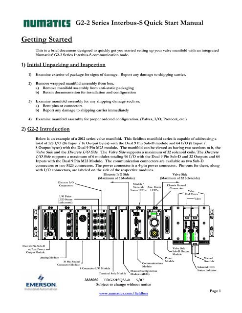
Below is an example of a 2012 series valve manifold. This fieldbus manifold series is capable of addressing a<br />
total of 128 I/O (16 Input / 16 Output bytes) with the Dual 9 Pin Sub-D module and 64 I/O (8 Input /<br />
8 Output bytes) with the Dual 9 Pin M23 module. The manifold can be viewed as having two sections to it, the<br />
Valve Side and the Discrete I/O Side. The Valve Side supports a maximum of 32 solenoid coils. The Discrete<br />
I/O Side supports a maximum of 6 modules totaling 96 I/O with the Dual 9 Pin Sub-D and 32 Outputs and 64<br />
Inputs with the Dual 9 Pin M23 Module. The communication connectors are available as two Sub-D<br />
connectors or two M23 connectors. The power connector is a 4-pin power connector. Pin-outs for these, along<br />
with I/O connectors, are labeled on the side of the respective modules.<br />
Valve Side<br />
(Maximum of 32 Solenoids)<br />
Module/<br />
Network<br />
Status LED's<br />
3835060<br />
TDG22ISQS3-0 5/07<br />
Subject to change without notice<br />
www.numatics.com/fieldbus<br />
Aux. Power<br />
LED's<br />
FUSE 1<br />
+24V VLV/OUT<br />
FUSE 2<br />
+24V NODE/IN<br />
Communications<br />
Module<br />
Chassis Ground<br />
Connection<br />
Valve<br />
End Plates<br />
Valve Side<br />
Sub-D Output<br />
Module<br />
Power<br />
Module<br />
Valve<br />
Manual<br />
Override<br />
Solenoid LED<br />
Status Indicator<br />
Page 1
G2-2 Series Interbus-S Quick Start Manual<br />
3) Interbus-S Communication Module Part Numbers<br />
Interbus-S Communication Replacement Part Numbers<br />
Connector Type Description Part Number<br />
Complete Module 239-2117<br />
Communication Board 240-197<br />
9 Pin Sub-D<br />
Auxiliary Power Board<br />
Valve Driver Board<br />
256-858<br />
256-680<br />
9 Pin M23<br />
4 Amp Fuse 140-933<br />
10 Amp Fuse 140-934<br />
Complete Module 240-200<br />
Communication Board 256-995<br />
Valve Driver Board 256-680<br />
4 Amp Fuse 140-933<br />
10 Amp Fuse 140-934<br />
TDG22ISQS3-0 5/07<br />
Subject to change without notice<br />
www.numatics.com/fieldbus<br />
Page 2
G2-2 Series Interbus-S Quick Start Manual<br />
4) MCM – Manual Configuration Module (Optional)<br />
Rotary Switch<br />
(SW3)<br />
Rotary Switch<br />
(SW4)<br />
The MCM is the module that allows the user to manually set the I/O Size, Byte Swap, and to test the<br />
<strong>Numatics</strong> manifold using Self-Test mode. The MCM consists of two DIP switch sets (SW1 and SW2) and two<br />
rotary switches (SW3 and SW4).<br />
MCM Module Part Numbers<br />
ON<br />
DIP Switch<br />
(SW2)<br />
1 2 3 4 5 6 7 8<br />
DIP Switch<br />
(SW1)<br />
All DIP switches shown in the "OFF" position<br />
ON<br />
1 2 3 4 5 6 7 8<br />
Description Part Number<br />
Complete Module 239-1384<br />
Replacement Board 256-684<br />
TDG22ISQS3-0 5/07<br />
Subject to change without notice<br />
www.numatics.com/fieldbus<br />
Page 3
MCM Settings<br />
DIP Switch Settings (SW1)<br />
G2-2 Series Interbus-S Quick Start Manual<br />
I/O Size (SW1-6) and Node ID (SW1-7):<br />
Byte Swap:<br />
Switch Description<br />
SW1-6 SW1-7 ID PCP<br />
Words<br />
Actual I/O Size for<br />
9 Pin Sub-d Version<br />
Actual I/O Size for<br />
M23 Version<br />
Off** Off** F3 1 8 Words I/O and 1 Word PCP N/A<br />
On* Off* F3 1 9 Words I/O and 1 Word PCP N/A<br />
Off On 3 0 8 Words I/O and 0 Word PCP 4 Words I/O and 0 Word PCP<br />
On On 3 0 10 Words I/O and 0 Word PCP 4 Words I/O and 0 Word PCP<br />
The manifold’s Input and Output bytes can appear be to swapped depending on the type of master and<br />
slave combination that is used. IBM and Motorola microprocessor ICs use the “Big Endian” architecture<br />
for handling memory storage. Intel microprocessors use the “Little Endian” architecture. For example,<br />
using the “Little Endian” architecture the hex word 0x1234 is stored in memory with its low byte ahead of<br />
its high byte, 0x34 0x12. While with the “Big Endian” architecture, the same hex word would be stored as<br />
0x12 0x34 (high byte ahead of its low byte).<br />
The MCM’s byte swap features allows users to swap the bytes in the manifold to resolve the “Big Endian”<br />
“Little Endian” scenario. Thus, making I/O mapping more intuitive and easier to deal with in<br />
programming.<br />
Switch Setting Description<br />
SW1-8 Off* Byte swap disabled<br />
SW1-8 On Byte swap enabled<br />
*Factory Default Settings<br />
*NOT available for the M23 connector version<br />
TDG22ISQS3-0 5/07<br />
Subject to change without notice<br />
www.numatics.com/fieldbus<br />
Page 4
5) Self-Test Mode<br />
G2-2 Series Interbus-S Quick Start Manual<br />
An internal diagnostic tool can also be enabled using the optional MCM module. This tool allows the user to<br />
confirm that all of the Inputs and Outputs on the manifold are fully functional without needing a network<br />
connection or controller. There are two test modes that the user can choose using SW2-8. The “Output” test<br />
mode tests all the outputs by sequentially turning them ON one at a time. The “Input/Output” test mode<br />
tests the inputs by causing all of the outputs to toggle between even and odd values when any input is made.<br />
To use the Self-Test Mode, the user must first set some initial conditions using the MCM module. Follow<br />
these steps to obtain the needed initial condition settings. Remember to remove power from the manifold<br />
before making changes to the MCM when setting these initial conditions.<br />
1) Disconnect power and air from the manifold!<br />
2) Record current MCM settings.<br />
3) Set the rotary switches to 99 (SW3 and SW4).<br />
4) Make sure that SW1-5, SW2-1, and SW2-7 are in the “ON” position.<br />
5) Select the desired test mode with SW2-8 (see table below)<br />
Switch Testing<br />
Setting<br />
Mode<br />
Description<br />
Output Off Sequentially turns all the outputs ON and OFF.<br />
SW2-8 Input/<br />
Output On<br />
Causes all of the odd outputs to come on and stay on until an<br />
input is made. When an input is made, the outputs will toggle to<br />
the even outputs.<br />
6) Make sure that all of the other switches are in the “OFF” position.<br />
The initial conditions are now set. To enable the Self-Test Mode, apply power to the manifold and make the<br />
following changes within 2 to 5 seconds:<br />
1) Set SW2-6 to the “ON” position.<br />
2) Set SW2-7 to the “OFF” position.<br />
Self-Test Mode is terminated by removing power to the unit. Remember to return the MCM settings to their<br />
original settings to return the communication node to normal operation.<br />
!<br />
• Air should be disconnected to the manifold when attempting to run the<br />
Self-Test Mode to prevent unwanted motion.<br />
• Communication lines should be disconnected before attempting to run the<br />
Self-Test Mode.<br />
TDG22ISQS3-0 5/07<br />
Subject to change without notice<br />
www.numatics.com/fieldbus<br />
Page 5
6) I/O Mapping Example<br />
Example:<br />
Assumed Settings<br />
- Single Z-Boards TM used with single solenoid<br />
valves<br />
- Double Z-Boards TM used with double<br />
solenoid valves<br />
- Master / Slave combination without byte<br />
swapping occurring or with appropriate MCM<br />
setting.<br />
Discrete I/O Configuration<br />
Pos<br />
No.<br />
Module Type Part No.<br />
In Out<br />
Bytes<br />
1 MCM 239-1384 -- --<br />
2<br />
8O Sourcing<br />
(PNP)<br />
239-1315 1 1<br />
3<br />
16O Sourcing<br />
(PNP)<br />
239-1319 1 2<br />
4<br />
4I Sinking<br />
(NPN)<br />
239-1304 1 0<br />
5<br />
8I Sinking<br />
(NPN)<br />
239-1308 1 0<br />
How to Order<br />
G2-2 Series Interbus-S Quick Start Manual<br />
Valve Size: 4 4<br />
Total: 8 7<br />
Qty Part Number<br />
1 AKCGI00003NDRM<br />
3 123BA4Z1MN00061<br />
2 123BB4Z2MN00061<br />
3 123BA4Z1MN00061<br />
1 123BB4Z2MN00061<br />
1 NXGIS1224DFG08<br />
1 239-1315<br />
1 239-1319<br />
1 239-1304<br />
1 239-1308<br />
TDG22ISQS3-0 5/07<br />
Subject to change without notice<br />
www.numatics.com/fieldbus<br />
When the 12 End<br />
Solenoid is<br />
energized, the 2 port<br />
is pressurized.<br />
When the 14 End<br />
Solenoid is<br />
energized, the 4 port<br />
is pressurized.<br />
Page 6
I/O Mapping Table Example Continued<br />
G2-2 Series Interbus-S Quick Start Manual<br />
BYTE Bit 7 Bit 6 Bit 5<br />
Output Table<br />
Bit 4 Bit 3 Bit 2 Bit 1 Bit 0<br />
0<br />
1<br />
2<br />
3<br />
4<br />
5<br />
6<br />
Valve Coil<br />
No. 8<br />
Allocated &<br />
Reserved<br />
Allocated &<br />
Reserved<br />
Allocated &<br />
Reserved<br />
Discrete<br />
Output No. 7<br />
Discrete<br />
Output No. 7<br />
Discrete<br />
Output No. 15<br />
Valve Coil<br />
No. 7<br />
Allocated &<br />
Reserved<br />
Allocated &<br />
Reserved<br />
Allocated &<br />
Reserved<br />
Discrete<br />
Output No. 6<br />
Discrete<br />
Output No. 6<br />
Discrete<br />
Output No. 14<br />
Valve Coil<br />
No. 6<br />
Allocated &<br />
Reserved<br />
Allocated &<br />
Reserved<br />
Allocated &<br />
Reserved<br />
Discrete<br />
Output No. 5<br />
Discrete<br />
Output No. 5<br />
Discrete<br />
Output No. 13<br />
Valve Coil<br />
No. 5<br />
Allocated &<br />
Reserved<br />
Allocated &<br />
Reserved<br />
Allocated &<br />
Reserved<br />
Discrete<br />
Output No. 4<br />
Discrete<br />
Output No. 4<br />
Discrete<br />
Output No. 12<br />
Valve Coil<br />
No. 4<br />
Valve Coil<br />
No. 12<br />
Allocated &<br />
Reserved<br />
Allocated &<br />
Reserved<br />
Discrete<br />
Output No. 3<br />
Discrete<br />
Output No. 3<br />
Discrete<br />
Output No. 11<br />
TDG22ISQS3-0 5/07<br />
Subject to change without notice<br />
www.numatics.com/fieldbus<br />
Valve Coil<br />
No. 3<br />
Valve Coil<br />
No. 11<br />
Allocated &<br />
Reserved<br />
Allocated &<br />
Reserved<br />
Discrete<br />
Output No. 2<br />
Discrete<br />
Output No. 2<br />
Discrete<br />
Output No. 10<br />
Valve Coil<br />
No. 2<br />
Valve Coil<br />
No. 10<br />
Allocated &<br />
Reserved<br />
Allocated &<br />
Reserved<br />
Discrete<br />
Output No. 1<br />
Discrete<br />
Output No. 1<br />
Discrete<br />
Output No. 9<br />
Valve Coil<br />
No. 1<br />
Valve Coil<br />
No. 9<br />
Allocated &<br />
Reserved<br />
Allocated &<br />
Reserved<br />
Discrete<br />
Output No. 0<br />
Discrete<br />
Output No. 0<br />
Discrete<br />
Output No. 8<br />
BYTE Bit 7 Bit 6 Bit 5<br />
Input Table<br />
Bit 4 Bit 3 Bit 2 Bit 1 Bit 0<br />
0<br />
1<br />
2<br />
3<br />
4<br />
5<br />
6<br />
7<br />
Coil No. 8<br />
Status<br />
Coil No. 16<br />
Status<br />
Coil No. 24<br />
Status<br />
Coil No. 32<br />
Status<br />
Allocated &<br />
Reserved<br />
Allocated &<br />
Reserved<br />
Allocated &<br />
Reserved<br />
Discrete<br />
Input No. 7<br />
Coil No. 7<br />
Status<br />
Coil No. 15<br />
Status<br />
Coil No. 23<br />
Status<br />
Coil No. 31<br />
Status<br />
Allocated &<br />
Reserved<br />
Allocated &<br />
Reserved<br />
Allocated &<br />
Reserved<br />
Discrete<br />
Input No. 6<br />
Coil No. 6<br />
Status<br />
Coil No. 14<br />
Status<br />
Coil No. 22<br />
Status<br />
Coil No. 30<br />
Status<br />
Allocated &<br />
Reserved<br />
Allocated &<br />
Reserved<br />
Allocated &<br />
Reserved<br />
Discrete<br />
Input No. 5<br />
Coil No. 5<br />
Status<br />
Coil No. 13<br />
Status<br />
Coil No. 21<br />
Status<br />
Coil No. 29<br />
Status<br />
Allocated &<br />
Reserved<br />
Allocated &<br />
Reserved<br />
Allocated &<br />
Reserved<br />
Discrete<br />
Input No. 4<br />
Coil No. 4<br />
Status<br />
Coil No. 12<br />
Status<br />
Coil No. 20<br />
Status<br />
Coil No. 28<br />
Status<br />
Allocated &<br />
Reserved<br />
Status for<br />
Discrete<br />
Outputs<br />
No.12-15<br />
Discrete<br />
Input No. 3<br />
Discrete<br />
Input No. 3<br />
Coil No. 3<br />
Status<br />
Coil No. 11<br />
Status<br />
Coil No. 19<br />
Status<br />
Coil No. 27<br />
Status<br />
Allocated &<br />
Reserved<br />
Status for<br />
Discrete<br />
Outputs<br />
No. 8-11<br />
Discrete<br />
Input No. 2<br />
Discrete<br />
Input No. 2<br />
Coil No. 2<br />
Status<br />
Coil No. 10<br />
Status<br />
Coil No. 18<br />
Status<br />
Coil No. 26<br />
Status<br />
Status for<br />
Discrete<br />
Outputs<br />
No. 4-7<br />
Status for<br />
Discrete<br />
Outputs<br />
No. 4-7<br />
Discrete<br />
Input No. 1<br />
Discrete<br />
Input No. 1<br />
Coil No. 1<br />
Status<br />
Coil No. 9<br />
Status<br />
Coil No. 17<br />
Status<br />
Coil No. 25<br />
Status<br />
Status for<br />
Discrete<br />
Outputs<br />
No. 0-3<br />
Status for<br />
Discrete<br />
Outputs<br />
No. 0-3<br />
Discrete<br />
Input No. 0<br />
Discrete<br />
Input No. 0<br />
Page 7
G2-2 Series Interbus-S Quick Start Manual<br />
7) Output Short Circuit Protection (Status Input Bits)<br />
Status Input Bits report the integrity of the load being driven by the output driver. They must be mapped to the<br />
scanner as part of the Input Size Value. Please refer to the table below for Status Input Bit action during fault<br />
condition:<br />
Output Type Output State Fault Condition Status Bit<br />
Valve Solenoid Coil Driver or<br />
Sinking (NPN)<br />
Discrete Outputs<br />
ON<br />
OFF<br />
No Fault<br />
Fault - Short Circuit, Over Temp/Over Current<br />
No Fault<br />
Fault - Open Load<br />
0<br />
1<br />
0<br />
1<br />
Sourcing (PNP)<br />
Discrete Outputs<br />
ON<br />
No Fault<br />
Fault - Short Circuit, Over Temp/Over Current<br />
0<br />
1<br />
8) Ground Wiring<br />
All <strong>Numatics</strong> Inc. communication nodes should be grounded during the installation process. These grounding<br />
guidelines can be found in National Electrical code IEC 60204-1 or EN 60204-1. There also is a,<br />
“ATTENTION: CONNECT TO EARTH GROUND FOR PROPER GROUNDING OF UNIT”, label<br />
attached to the chassis ground connection point on the G2-2 series communication node housing. This label<br />
also points out where the grounding guidelines can be found.<br />
!<br />
• Proper grounding will alleviate and prevent many intermittent problems<br />
with network communication.<br />
• When grounding to a machine frame, please ensure that the machine frame<br />
itself is already properly grounded.<br />
• Better grounding can be achieved when larger diameter (lower gauge) wire<br />
is used.<br />
TDG22ISQS3-0 5/07<br />
Subject to change without notice<br />
www.numatics.com/fieldbus<br />
Page 8
G2-2 Series Interbus-S Quick Start Manual<br />
9) Communication Module Connector Pin-Out<br />
Interbus-S Communication 9 Pin Sub-D Connector Pin-Out<br />
BUS IN<br />
BUS IN and BUS OUT 9 Pin Sub-D Connector Pin-Out<br />
BUS OUT<br />
Pin No. Male Pin Female Pin<br />
Description<br />
Function Function<br />
1 DO1 DO2 Data Output signal<br />
2 DI1 DI2 Data Input signal<br />
3 GND GND Signal Ground<br />
4 NC NC No Connection<br />
5 NC GND<br />
Male = No Connection<br />
Female = Signal Ground<br />
6 DO1 DO2 Inverted Data Output signal<br />
7 DI1 DI2 Inverted Data Input signal<br />
8 NC NC No Connection<br />
Male = No Connection<br />
9 NC RSBT Female = Used to signify the last node on the bus. No connection = last<br />
node; connect to GND pin = additional nodes on the bus<br />
Case Earth Ground Earth Ground Protective Earth (Case Ground)<br />
TDG22ISQS3-0 5/07<br />
Subject to change without notice<br />
www.numatics.com/fieldbus<br />
Page 9
G2-2 Series Interbus-S Quick Start Manual<br />
Interbus-S Communication M23 Connector Pin-Out<br />
BUS IN<br />
BUS IN and BUS OUT 9 Pin Sub-D Connector Pin-Out<br />
BUS OUT<br />
Pin No. Male Pin Female Pin<br />
Description<br />
Function Function<br />
1 DO1 DO2 Data Output signal<br />
2 DO1 DO2 Inverted Data Output signal<br />
3 DI1 DI2 Data Input signal<br />
4 DI1 DI2 Inverted Data Input signal<br />
5 GND GND Signal Ground<br />
6 Earth Ground Earth Ground Protective Earth (Case Ground)<br />
7 +24V +24V +24V Power<br />
8 0V 0V 0V Common<br />
Male = No Connection<br />
9 NC RSBT Female = Used to signify the last node on the bus. No connection = last<br />
node; connect to GND pin = additional nodes on the bus<br />
Case Earth Ground Earth Ground Protective Earth (Case Ground)<br />
TDG22ISQS3-0 5/07<br />
Subject to change without notice<br />
www.numatics.com/fieldbus<br />
Page 10
10) Auxiliary Power Connector Pin-Out<br />
!<br />
G2-2 Series Interbus-S Quick Start Manual<br />
Pin No. Function Description<br />
1<br />
+24VDC<br />
(Valves and Outputs)<br />
Voltage Used to Power Outputs<br />
(Valve Coils and Discrete Outputs)<br />
2 Earth Ground Protective Earth (Case Ground)<br />
3 0VDC Common 0VDC Common, for Valves, I/O, and Node Power<br />
4<br />
+24VDC<br />
(Node and Inputs)<br />
Voltage Used to Power Discrete Inputs and Node Electronics<br />
4<br />
1 3<br />
2<br />
• Maximum current capacity on the 0VDC common pin of the auxiliary<br />
power connector is 8 Amps. The combined draw of the +24VDC Valves and<br />
Outputs and +24VDC Node and Inputs pins cannot exceed 8 Amps, at any<br />
given moment in time.<br />
• The auxiliary power +24VDC Node and Inputs pin supplies power to the<br />
node electronics. This pin must be powered at all times for communication<br />
node to be functional.<br />
TDG22ISQS3-0 5/07<br />
Subject to change without notice<br />
www.numatics.com/fieldbus<br />
Page 11
11) Power Consumption<br />
Auxiliary Power Connection (Standard)<br />
G2-2 Series Interbus-S Quick Start Manual<br />
Aux. Power<br />
Description<br />
Connector Pin No.<br />
1 24 VDC Power for Valves & Discrete Outputs<br />
4 24 VDC Power for Inputs & Node Electronics<br />
Discrete I/O Module(s) Power Jumper<br />
All of <strong>Numatics</strong>, Inc., G2-2 I/O modules have a selectable power source jumper. This jumper determines<br />
which Aux. Power connector pin will power these modules.<br />
This option allows the user to select how each specific module will be powered during different conditions<br />
(i.e. E-Stop). Each I/O module can be set-up independently allowing individual Output and/or Input<br />
modules to remain active if needed.<br />
Power Rating<br />
• Maximum system current capability is 8 amps. Care should be taken not to exceed 8 amp draw<br />
through the 0VDC common pin (Current through all +24 VDC Pins combined).<br />
• Discrete I/O current draw is dependent on the device(s) connected. It is critical to know what these<br />
values are in order to remain safely within the 8 amp limitation.<br />
• Loads should not draw more than 0.5 amps of current from any one individual discrete output point.<br />
(Contact factory for higher current capabilities)<br />
Auxiliary Power Connector Voltage Tolerance Current Power<br />
+24VDC (Valves & Outputs)<br />
Solenoid Valve Coil 2005 (Each) 24VDC +10%/-15% 0.042 A 1.0 Watts<br />
Solenoid Valve Coil 2012 (Each) 24VDC +10%/-15% 0.105 A 2.5 Watts<br />
Solenoid Valve Coil 2035 (Each) 24VDC +10%/-15% 0.105 A 2.5 Watts<br />
Solenoid Valve Coil ISO - SPA (Each) 24VDC +10%/-15% 0.160 A 4.0 Watts<br />
Discrete Output 24VDC - 0.5 A max. * 12 Watts max. *<br />
Discrete I/O Status LEDs (Each) 24VDC - 0.015 A 0.36 Watts<br />
+24VDC (Node & Inputs)<br />
Node 24VDC +/- 10% 0.040 A 0.96 Watts<br />
Discrete I/O Module (Each) 24VDC - 0.006 A 0.14 Watts<br />
Discrete I/O Status LEDs (Each) 24VDC - 0.015 A 0.36 Watts<br />
Recommended External Fuses:<br />
• Power consumption for each Discrete I/O point is dependent on the<br />
specific current draw of input sensor devices and output loads. Please<br />
consult the factory for output current requirements greater than 0.5 amps.<br />
External fuses should be chosen based upon the physical manifold configuration. Please refer to the next<br />
page for the fuse sizing chart.<br />
TDG22ISQS3-0 5/07<br />
Subject to change without notice<br />
www.numatics.com/fieldbus<br />
Page 12
G2-2 Series Interbus-S Quick Start Manual<br />
12) Power Consumption and External Sizing Guide Chart<br />
Power Consumption - Aux. Power Connector Pin for Valves and Outputs<br />
Description Current<br />
Number of Solenoid Valve Coils Energized Simultaneously<br />
___ X 0.105 A (2012 and 2035 Series) = __________Amps<br />
___ X 0.042 A (2005 Series)<br />
Total load current drawn by simultaneously energized Discrete Outputs<br />
with Discrete Outputs Power Jumper in “SP” Position (Factory Default).<br />
TDG22ISQS3-0 5/07<br />
Subject to change without notice<br />
www.numatics.com/fieldbus<br />
= __________Amps<br />
+<br />
=<br />
__________Amps<br />
+<br />
Total load current drawn by Sensor Devices from Discrete Inputs source<br />
with Discrete Input Power Jumper in “SP” Position.<br />
= __________Amps<br />
Total: __________Amps<br />
Surge Compensation: X 1.25<br />
Suggested External +24 VDC (Valves and Outputs) Fuse Value: __________Amps<br />
Power Consumption - Aux. Power Connector Pin for Node and Inputs<br />
Description Current<br />
Communication Node Power Consumption = .040 Amps<br />
+<br />
Total load current drawn by simultaneously energized Discrete Outputs<br />
with Discrete Outputs Power Jumper in “UP” Position.<br />
=<br />
__________Amps<br />
+<br />
Total load current drawn by Sensor Devices from Discrete Inputs source<br />
with Discrete Inputs Power Jumper in “UP” Position (Factory Default).<br />
= __________Amps<br />
+<br />
Number of I/O modules installed ___ X 0.006 A = __________Amps<br />
+<br />
Number of Discrete I/O Status LEDs simultaneously on ___ X 0.015 A = __________Amps<br />
Total: __________Amps<br />
Surge Compensation: X 1.25<br />
Suggested External Pin +24 VDC (Node and Inputs) Fuse Value: __________Amps<br />
• The standard power jumper configuration for all Output Modules is “SP”.<br />
• The standard power jumper configuration for all Input Modules is “UP”.<br />
• At any given moment in time, the combined current draw through<br />
+24VDC (Valves & Outputs) pin and +24VDC (Node & Inputs) pin<br />
cannot exceed 8 amps. Therefore, the combined value of the external<br />
fuses on the two +24VDC pins should not exceed 8 amps.<br />
• The internal fuses are installed to protect against fire damage due to<br />
catastrophic failure of internal components. External fuses are<br />
recommended for protection against power supply failure, over-current<br />
conditions, etc…<br />
Page 13
13) LED Functions<br />
G2-2 Series Interbus-S Quick Start Manual<br />
9 Pin Sub-D Interbus-S Communication Module<br />
Upon power up, the LEDs indicate the status of the unit. The Power Module of the G2-2 Interbus-S node has<br />
four LEDs; two for internal fuse integrity and two for Aux. Power status. The Communication module also<br />
has four status LEDs which are described below.<br />
Communication Module<br />
LED Name Color Status Description<br />
BA<br />
(Bus Active)<br />
TR<br />
(Transmit /<br />
Receive)<br />
CC<br />
(Cable Check)<br />
RD<br />
(Remote Bus<br />
Disable)<br />
Green<br />
ON Bus is active.<br />
FLASHING I/O Size Configuration mismatch.<br />
Green ON Active when PCP communication is made over the Interbus-S Network<br />
Green ON The cable connection is good, and the Interbus-S Master is not in reset<br />
Red ON On when the outgoing remote bus is switched off.<br />
Power Module<br />
LED Name Color Status Description<br />
FUSE 1 Red<br />
+24V VLV/OUT Green<br />
FUSE 2 Red<br />
+24V NODE/IN Green<br />
OFF<br />
Internal fuse F1 is OK (valid only when power is applied to<br />
+24V VLV / OUT pin on Aux. Power connector).<br />
ON<br />
Internal fuse F1 is open; No power is internally provided to valves or<br />
outputs. Communication NOT affected.<br />
OFF No DC Power present at +24V VLV / OUT pin on Aux. Power connector.<br />
ON DC Power applied to +24V VLV / OUT pin on Aux. Power Connector.<br />
OFF<br />
Internal fuse F2 is OK (valid only when power is applied to<br />
+24V NODE / IN pin on Aux. Power connector.<br />
ON<br />
Internal fuse F2 is open; No power is internally provided to node<br />
electronics or inputs. Communication Node will not function.<br />
OFF No DC Power present at +24V NODE / IN pin on Aux. Power connector.<br />
ON DC Power applied to+24V NODE / IN pin on Aux. Power connector.<br />
TDG22ISQS3-0 5/07<br />
Subject to change without notice<br />
www.numatics.com/fieldbus<br />
Page 14
G2-2 Series Interbus-S Quick Start Manual<br />
M23 Interbus-S Communication Module<br />
Upon power up, the LEDs indicate the status of the unit. The Power Module of the G2-2 Interbus-S node has<br />
four LEDs; two for internal fuse integrity and two for Aux. Power status. The Communication module also<br />
has four status LEDs which are described below.<br />
LED Name<br />
TR<br />
Color Status Description<br />
(Transmit /<br />
Receive)<br />
RD<br />
Green ON Active when PCP communication is made over the Interbus-S Network<br />
(Remote Bus<br />
Disable)<br />
Red ON On when the outgoing remote bus is switched off.<br />
BA<br />
(Bus Active)<br />
Green ON Bus is active.<br />
CC<br />
(Cable Check)<br />
+24V/F1<br />
(VLV/OUT)<br />
+24V/F2<br />
(NODE/IN)<br />
Green ON The cable connection is good, and the Interbus-S Master is not in reset<br />
Green<br />
Green Red<br />
Green<br />
Green Red<br />
OFF No DC Power present at +24V VLV / OUT pin on Aux. Power connector.<br />
ON DC Power applied to +24V VLV / OUT pin on Aux. Power Connector.<br />
OFF<br />
Internal fuse F1 is OK (valid only when power is applied to<br />
+24V VLV / OUT pin on Aux. Power connector).<br />
ON<br />
Internal fuse F1 is open; No power is internally provided to valves or<br />
outputs. Communication NOT affected.<br />
OFF No DC Power present at +24V NODE / IN pin on Aux. Power connector.<br />
ON DC Power applied to+24V NODE / IN pin on Aux. Power connector.<br />
OFF<br />
Internal fuse F2 is OK (valid only when power is applied to<br />
+24V NODE / IN pin on Aux. Power connector.<br />
ON<br />
Internal fuse F2 is open; No power is internally provided to node<br />
electronics or inputs. Communication Node will not function.<br />
TDG22ISQS3-0 5/07<br />
Subject to change without notice<br />
www.numatics.com/fieldbus<br />
Page 15
14) Jumper Settings<br />
Status Bit Jumper Settings<br />
Jumper<br />
Settings<br />
15) Node ID<br />
Jumpered<br />
Pins<br />
G2-2 Series Interbus-S Quick Start Manual<br />
TDG22ISQS3-0 5/07<br />
Subject to change without notice<br />
www.numatics.com/fieldbus<br />
Description<br />
ON Factory Default – Status bits from valve drivers are enabled.<br />
OFF Status bits from valve drivers are disabled.<br />
<strong>Numatics</strong>’ 9 Pin Sub-D Interbus-S node supports 4 different operating modes selected by the node ID<br />
parameter chosen by the user with the appropriate software. <strong>Numatics</strong>’ M23 Interbus-S node supports 1<br />
operating mode selected by the node ID parameter. PCP is a standard method of transferring large amounts of<br />
data, one byte at a time, through an Interbus-S network. Process data is the main communications element of<br />
an Interbus-S network. It is the high-speed value that is updated every scan cycle.<br />
Node ID Hex Node ID Decimal Description<br />
3* 3* Only Process data<br />
F0 240 Process data + 2 PCP Words<br />
F1 241 Process data + 4 PCP Words<br />
F3 243 Process data + 1 PCP Words<br />
*Only option that is available for the M23 connector version<br />
Page 16
16) Factory Default Settings<br />
G2-2 Series Interbus-S Quick Start Manual<br />
Unless otherwise requested, all standard G2-2 Series Interbus-S manifolds ship with specific factory default<br />
settings. Below is a list of the factory default settings:<br />
Description Default Settings<br />
Node Address 0<br />
Baud Rate 5 Mbit/sec<br />
PU<br />
Input Module Power Jumper<br />
(Input sensor power supplied by<br />
+24VDC Node and Inputs pin on the Aux. power connector)<br />
SP<br />
Output Module Power Jumper<br />
(Output module power supplied by<br />
+24VDC Valves and Outputs pin on the Aux. power connector)<br />
Valve Side Output Bytes 4 Bytes (32 Allocated Valve Coil Outputs)<br />
Discrete I/O Side - I/O Bytes Self-Configuring based on the I/O modules installed.<br />
17) Technical Support<br />
For technical support, contact your local <strong>Numatics</strong> distributor. If further information is required,<br />
please call <strong>Numatics</strong> Inc. at (248) 887-4111 and ask for Technical Support.<br />
Issues relating to network set-up, PLC programming, sequencing, software related functions, etc…<br />
should be handled with the appropriate product vendor.<br />
Information on device files, technical manuals, local distributors, and other <strong>Numatics</strong>, Inc. products<br />
and support issues can be found on the <strong>Numatics</strong>, Inc’s. WEB site at www.numatics.com<br />
TDG22ISQS3-0 5/07<br />
Subject to change without notice<br />
www.numatics.com/fieldbus<br />
Page 17


