

Getting Started - ASCO Numatics
Getting Started - ASCO Numatics
Getting Started - ASCO Numatics

You also want an ePaper? Increase the reach of your titles
YUMPU automatically turns print PDFs into web optimized ePapers that Google loves.
G2-2 Series Interbus-S Quick Start Manual<br />
7) Output Short Circuit Protection (Status Input Bits)<br />
Status Input Bits report the integrity of the load being driven by the output driver. They must be mapped to the<br />
scanner as part of the Input Size Value. Please refer to the table below for Status Input Bit action during fault<br />
condition:<br />
Output Type Output State Fault Condition Status Bit<br />
Valve Solenoid Coil Driver or<br />
Sinking (NPN)<br />
Discrete Outputs<br />
ON<br />
OFF<br />
No Fault<br />
Fault - Short Circuit, Over Temp/Over Current<br />
No Fault<br />
Fault - Open Load<br />
0<br />
1<br />
0<br />
1<br />
Sourcing (PNP)<br />
Discrete Outputs<br />
ON<br />
No Fault<br />
Fault - Short Circuit, Over Temp/Over Current<br />
0<br />
1<br />
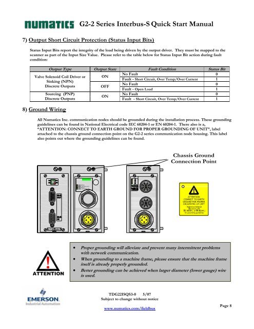
8) Ground Wiring<br />
All <strong>Numatics</strong> Inc. communication nodes should be grounded during the installation process. These grounding<br />
guidelines can be found in National Electrical code IEC 60204-1 or EN 60204-1. There also is a,<br />
“ATTENTION: CONNECT TO EARTH GROUND FOR PROPER GROUNDING OF UNIT”, label<br />
attached to the chassis ground connection point on the G2-2 series communication node housing. This label<br />
also points out where the grounding guidelines can be found.<br />
!<br />
• Proper grounding will alleviate and prevent many intermittent problems<br />
with network communication.<br />
• When grounding to a machine frame, please ensure that the machine frame<br />
itself is already properly grounded.<br />
• Better grounding can be achieved when larger diameter (lower gauge) wire<br />
is used.<br />
TDG22ISQS3-0 5/07<br />
Subject to change without notice<br />
www.numatics.com/fieldbus<br />
Page 8


