

Getting Started - ASCO Numatics
Getting Started - ASCO Numatics
Getting Started - ASCO Numatics

You also want an ePaper? Increase the reach of your titles
YUMPU automatically turns print PDFs into web optimized ePapers that Google loves.
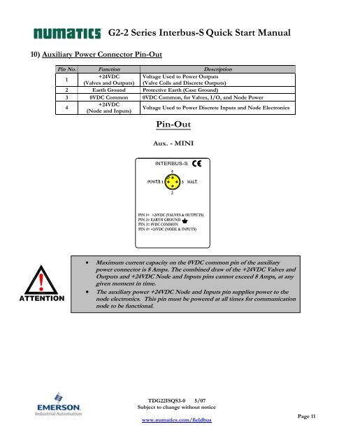
10) Auxiliary Power Connector Pin-Out<br />
!<br />
G2-2 Series Interbus-S Quick Start Manual<br />
Pin No. Function Description<br />
1<br />
+24VDC<br />
(Valves and Outputs)<br />
Voltage Used to Power Outputs<br />
(Valve Coils and Discrete Outputs)<br />
2 Earth Ground Protective Earth (Case Ground)<br />
3 0VDC Common 0VDC Common, for Valves, I/O, and Node Power<br />
4<br />
+24VDC<br />
(Node and Inputs)<br />
Voltage Used to Power Discrete Inputs and Node Electronics<br />
4<br />
1 3<br />
2<br />
• Maximum current capacity on the 0VDC common pin of the auxiliary<br />
power connector is 8 Amps. The combined draw of the +24VDC Valves and<br />
Outputs and +24VDC Node and Inputs pins cannot exceed 8 Amps, at any<br />
given moment in time.<br />
• The auxiliary power +24VDC Node and Inputs pin supplies power to the<br />
node electronics. This pin must be powered at all times for communication<br />
node to be functional.<br />
TDG22ISQS3-0 5/07<br />
Subject to change without notice<br />
www.numatics.com/fieldbus<br />
Page 11


