ISTWLR01.4865 Rev00 WALKY:Layout 1 - Fast Access Security Corp.
ISTWLR01.4865 Rev00 WALKY:Layout 1 - Fast Access Security Corp.
ISTWLR01.4865 Rev00 WALKY:Layout 1 - Fast Access Security Corp.

You also want an ePaper? Increase the reach of your titles
YUMPU automatically turns print PDFs into web optimized ePapers that Google loves.
<strong>WALKY</strong> WL1024<br />
WL1024C<br />
Swing gate opener<br />
EN - Instructions and warnings for installation and use<br />
IT - Istruzioni ed avvertenze per linstallazione e luso<br />
FR - Instructions et avertissements pour linstallation et lutilisation<br />
ES - Instrucciones y advertencias para la instalación y el uso<br />
DE - Installierungs-und Gebrauchsanleitungen und Hinweise<br />
PL - Instrukcje i ostrzeżenia do instalacji i użytkowania<br />
NL - Aanwijzingen en aanbevelingen voor installatie en gebruik
Contents<br />
ENGLISH<br />
1 - WARNINGS AND GENERAL PRECAUTIONS . . . . . . . . . . . . . . . . . . . . 1<br />
1.1 - Safety warnings . . . . . . . . . . . . . . . . . . . . . . . . . . . . . . . . . . . . . . . . . . 1<br />
1.2 - Warnings for installation . . . . . . . . . . . . . . . . . . . . . . . . . . . . . . . . . . . . 1<br />
1.3 - Warnings for use . . . . . . . . . . . . . . . . . . . . . . . . . . . . . . . . . . . . . . . . . . 1<br />
2 - PRODUCT DESCRIPTION AND INTENDED USE . . . . . . . . . . . . . . . . . 1<br />
3 - INSTALLATION . . . . . . . . . . . . . . . . . . . . . . . . . . . . . . . . . . . . . . . . . . . . 2<br />
3.1 - Pre-installation checks . . . . . . . . . . . . . . . . . . . . . . . . . . . . . . . . . . . . . 2<br />
3.2 - Usage limitation . . . . . . . . . . . . . . . . . . . . . . . . . . . . . . . . . . . . . . . . . . 2<br />
3.3 - Preparatory work prior to installation . . . . . . . . . . . . . . . . . . . . . . . . . . . 3<br />
3.4 - Installation of the gearmotor mod. WL1024C - WL1024 . . . . . . . . . . . . 3<br />
3.4.1 - Establishing the length of the gearmotor arm . . . . . . . . . . . . . . 3<br />
3.4.2 - Installation of a gearmotor with a STANDARD LENGTH ARM . . 3<br />
3.4.3 - Installation of a gearmotor with a SHORTENED ARM . . . . . . . . 4<br />
3.5 - Installation of the multi-purpose lamp mod. WLT on the gearmotor<br />
model WL1024C . . . . . . . . . . . . . . . . . . . . . . . . . . . . . . . . . . . . . . . . . . . . . . 5<br />
3.6 - How to remove the control unit . . . . . . . . . . . . . . . . . . . . . . . . . . . . . . . 5<br />
3.7 - Adjusting the alignment of the gate leaves when closed . . . . . . . . . . . . 5<br />
3.8 - Securing and releasing the gearmotor manually . . . . . . . . . . . . . . . . . . 5<br />
4 - ELECTRICAL CONNECTIONS . . . . . . . . . . . . . . . . . . . . . . . . . . . . . . . 5<br />
4.1 - Description of the electrical connections . . . . . . . . . . . . . . . . . . . . . . . . 5<br />
4.2 - Connecting the power cable . . . . . . . . . . . . . . . . . . . . . . . . . . . . . . . . . 6<br />
4.3 - Connecting the gearmotor without a control unit mod. WL1024 . . . . . . 5<br />
4.4 - Connecting other devices . . . . . . . . . . . . . . . . . . . . . . . . . . . . . . . . . . . 5<br />
4.5 - Addressing the connected devices . . . . . . . . . . . . . . . . . . . . . . . . . . . . 6<br />
4.6 - Initialisation and connection check . . . . . . . . . . . . . . . . . . . . . . . . . . . . 6<br />
4.7 - Recognition of the connected devices . . . . . . . . . . . . . . . . . . . . . . . . . 6<br />
4.8 - Recognition of the positions of the mechanical stops . . . . . . . . . . . . . . 6<br />
4.9 - Gate leaves motion check . . . . . . . . . . . . . . . . . . . . . . . . . . . . . . . . . . 6<br />
5 - TESTING AND COMMISSIONING . . . . . . . . . . . . . . . . . . . . . . . . . . . . . 6<br />
5.1 - Testing . . . . . . . . . . . . . . . . . . . . . . . . . . . . . . . . . . . . . . . . . . . . . . . . . 7<br />
5.2 - Commissioning . . . . . . . . . . . . . . . . . . . . . . . . . . . . . . . . . . . . . . . . . . . 7<br />
6 - PROGRAMMING THE CONTROL UNIT . . . . . . . . . . . . . . . . . . . . . . . . 7<br />
6.1 - Level one programming (ON-OFF) . . . . . . . . . . . . . . . . . . . . . . . . . . . . 7<br />
6.2 - Level two programming (adjustable parameters) . . . . . . . . . . . . . . . . . . 8<br />
6.3 - Memory deletion . . . . . . . . . . . . . . . . . . . . . . . . . . . . . . . . . . . . . . . . . . 8<br />
6.4 - Special functions . . . . . . . . . . . . . . . . . . . . . . . . . . . . . . . . . . . . . . . . . 8<br />
7 - WHAT TO DO IF... (troubleshooting guide) . . . . . . . . . . . . . . . . . . . . . . 9<br />
8 - FURTHER INFORMATION . . . . . . . . . . . . . . . . . . . . . . . . . . . . . . . . . . 10<br />
8.1 - Connection of the OXI radio receiver . . . . . . . . . . . . . . . . . . . . . . . . . . 10<br />
8.2 - Connection and installation of the back-up battery mod. PS424 . . . . . 10<br />
8.3 - Connection of the Oview programmer . . . . . . . . . . . . . . . . . . . . . . . . 10<br />
8.4 - Connection of the Solemyo solar power system . . . . . . . . . . . . . . . . . 10<br />
9 - PRODUCT MAINTENANCE . . . . . . . . . . . . . . . . . . . . . . . . . . . . . . . . . 10<br />
DISPOSING OF THE PRODUCT . . . . . . . . . . . . . . . . . . . . . . . . . . . . . . . . 11<br />
PRODUCT TECHNICAL SPECIFICATIONS . . . . . . . . . . . . . . . . . . . . . . . 11<br />
Product life span . . . . . . . . . . . . . . . . . . . . . . . . . . . . . . . . . . . . . . . . . . . . 12<br />
EC DECLARATION OF CONFORMITY . . . . . . . . . . . . . . . . . . . . . . . . . . . 12<br />
APPENDIX . . . . . . . . . . . . . . . . . . . . . . . . . . . . . . . . . . . . . . . . . . . . . . . . . . I<br />
Instructions and warnings for the user . . . . . . . . . . . . . . . . . . . . . . . . . . . . . III<br />
Images . . . . . . . . . . . . . . . . . . . . . . . . . . . . . . . . . . . . . . . . . . . . . . . . . . . . . X<br />
1<br />
WARNINGS AND GENERAL PRECAUTIONS<br />
1.1 - Safety warnings<br />
IMPORTANT! – This manual contains important instructions and warnings<br />
regarding safety. Incorrect installation may cause serious injury. Before<br />
commencing work, all sections of the manual must be read carefully. If in any<br />
doubt, suspend installation and call the Nice Support Service for clarification.<br />
IMPORTANT! – This manual contains important instructions. Keep it for<br />
future maintenance work and disposal of the product.<br />
IMPORTANT! – Under the latest European legislation, automatic door<br />
and gate installations must be compliant with the standards specified in<br />
Directive 2006/42/EC (formerly 98/37/EC) (the Machinery Directive) and<br />
the standards EN 12445, EN 12453, EN 12635 and EN 13241-1 in particular,<br />
which enable conformity of the automated functionality to be de -<br />
clared. In the light of the above, all work involving installation, connection,<br />
testing and maintenance of the product must be carried out<br />
exclusively by qualified and competent technicians!<br />
1.2 - Warnings for installation<br />
Before commencing the installation, check if the product is suitable for the<br />
desired type of use (see “Usage limitation” paragraph 3.2 and the "Product<br />
technical specifications”). If it is not suitable, DO NOT continue with the installation.<br />
All installation and maintenance work must be carried out with the au -<br />
tomation system disconnected from the electricity supply. If the power<br />
disconnection device cannot be seen from where the automation system is<br />
positioned, then before starting work a notice must be attached to the disconnection<br />
device bearing the words “CAUTION! MAINTENANCE IN PRO -<br />
GRESS”.<br />
The Control unit must be connected to an electricity supply line equipped<br />
with protective earthing.<br />
Handle the product with care during installation, taking care to avoid crushing,<br />
denting or dropping it, or contact with liquids of any kind. Keep the product<br />
away from sources of heat and naked flames. Failure to observe the<br />
above can damage the product, and increase the risk of danger or malfunction.<br />
Should this occur, suspend installation work immediately and contact<br />
the Nice Support Service.<br />
Do not modify any part of the product. Prohibited modifications can only lead<br />
to malfunctions. The manufacturer declines all responsibility for damage re -<br />
sulting from unauthorized changes made to the product.<br />
If the gate or door being automated has a pedestrian gate, then the system<br />
must include a control device that will inhibit the operation of the motor when<br />
the pedestrian gate is open.<br />
The products packaging material must be disposed of in full compliance with<br />
local regulations.<br />
1.3 - Warnings for use<br />
The product is not intended for use by persons, including children, with limited<br />
physical, sensory or mental capacities, or who lack experience or knowledge,<br />
unless supervised or trained in the use of the product by a person<br />
responsible for their safety.<br />
Any children near the automation system must be kept under supervision to<br />
ensure that they do not play with it.<br />
Do not allow children to play with the fixed control devices. Keep remote control<br />
devices out of the reach of children.<br />
2<br />
PRODUCT DESCRIPTION AND<br />
INTENDED USE<br />
The devices comprising this product are designed to automate a gate or door<br />
with one or two leaves. IMPORTANT! – Any other use apart from that<br />
described herein, including in different environmental conditions from<br />
those described in this manual is to be considered improper use and is<br />
not permitted!<br />
The principal component of the automation system comprises one or two electric<br />
gearmotors (according to the number of leaves to be automated), each<br />
equipped with a direct current motor and epicyclic reduction gear. One of the<br />
gearmotors (mod. WL1024C) has a control unit that controls its operation. The<br />
Control unit consists of a board with a radio receiver for receiving the commands<br />
sent by the transmitter.<br />
The control unit is designed for connection to several devices belonging to the<br />
Opera system, the Bluebus system and the Solemyo solar powered system.<br />
If it is mains powered, it can house a back-up battery (mod. PS424, optional<br />
accessory) which in the event of a power cut (electricity black-out) guarantees<br />
that the automated device will perform certain manoeuvres in the hours that follow.<br />
In the event of a power cut, the gate leaves can be moved by releasing the<br />
gearmotor with the dedicated key; to perform the manoeuvre manually please<br />
see chapter 3.8.<br />
English – 1<br />
EN
EN<br />
Other available accessories include the receivers designed with “SM” connectors<br />
(SMXI, OXI, etc.).<br />
The gearmotor with control unit (mod. WL1024C) is designed to accommodate<br />
the installation of the multi-purpose lamp mod. WLT (see chapter 3.5), which<br />
can operate as a flashing emergency light or courtesy light, depending on the<br />
control unit programming. In addition, it can be used as a twilight by activating<br />
a built-in light sensor; please refer to the relevant instruction manual for specifications.<br />
3<br />
3.1 - Pre-installation checks<br />
Before going ahead with the installation, check the integrity of the product components,<br />
and ensure the model chosen is suitable for its intended use and for<br />
the environment in which it is to be installed.<br />
Check that all the material to be used is in excellent condition and suitable for<br />
its intended use.<br />
Check that the ground-mounted mechanical stops are present both when<br />
opening and closing the automation system.<br />
Check that the mechanical structure of the gate is suitable for the installation<br />
of automation and compliant with locally applicable regulations (if necessary,<br />
refer to the label on the gate). This product cannot be used to automate a<br />
gate which is not already in good, safe working order, neither can it fix faults<br />
caused by incorrect installation or poor maintenance of the gate.<br />
Check that the operating conditions of the devices are compatible with the<br />
usage limitation declared (see paragraph 3.2).<br />
Move the gate leaves manually in both directions and ensure that the resistance<br />
to movement is constant at all points of travel (there should not be any<br />
points where more force or less is required).<br />
Bring the gate leaves manually into a position at random, then let go and<br />
check that they remain stationary.<br />
Check that the gearmotor fixing zone is compatible with its overall dimensions<br />
(fig. 1).<br />
Check that the place where the gearmotor is to be installed allows enough<br />
space for its arm to execute its full range of movement.<br />
Check that there is sufficient room around the gearmotor for it to be released<br />
manually when required.<br />
Ensure that the surfaces on which the various devices are to be installed are<br />
strong and capable of ensuring a firm hold.<br />
Ensure that each device is installed in a position which is protected and does<br />
not expose it to accidental impacts.<br />
Ensure that all the electrical cables to be used are the type listed in Table 1.<br />
3.2 - Usage limitation<br />
Before installing the gearmotor, check that its data complies with the usage limitation<br />
specified below and falls within the limits stated in the chapter entitled<br />
“Product technical specifications”:<br />
With FULL LENGTH motor arm (as shipped from the factory):<br />
- maximum width of leaf: 1.60 m (= maximum weight of leaf: 110 kg)<br />
- maximum height of leaf: 2 m<br />
With SHORTENED motor arm (cut by the installer):<br />
- maximum width of leaf: 1.60 m (= maximum weight of leaf: 100 kg)<br />
- maximum height of leaf: 2 m<br />
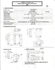
Check to run: apply to Graph 1 the weight and width of the leaf; plot two lines<br />
from these points and check that they intersect in one of the two grey areas of<br />
the graph. Important! - If the lines cross in the white area, this product cannot<br />
be used to automate this particular gate.<br />
To enable the installation of the gearmotor, the minimum width of the column<br />
should be 80 mm.<br />
2 – English<br />
INSTALLATION<br />
TABLE 1 - Technical characteristics of the electrical cables<br />
The gearmotor arm must be positioned in the upper part of the gate leaf.<br />
IMPORTANT! - The gearmotor must not be mounted upside down, i.e. with<br />
the arm pointing downwards.<br />
The arms fastening bracket must be fitted at one of the strongest parts of the<br />
leaf (e.g. the frame), in order to ensure a firm and safe hold;<br />
Check distance “E” (fig. 7):<br />
- If distance “E” falls in the range 80 mm (minimum) to 299 mm (maximum),<br />
the gearmotor arm will need to be shortened. In such conditions, the leaf will<br />
be able to open by up to 90°.<br />
- If distance “E” is 300 mm or more, there is no need to shorten the gearmotor<br />
arm. In such conditions, the leaf will be able to open by up to 110°.<br />
3.3 - Preparatory work prior to installation<br />
Fig. 2 illustrates an example of an automated system, achieved using Nice<br />
components:<br />
a - Gearmotor with control unit mod. WL1024C<br />
b - Gearmotor without control unit mod. WL1024<br />
c - Multi-purpose lamp mod. WLT (to be installed on the gearmotor with control<br />
unit mod. WL1024C); see chapter 3.5 and the lamps own instruction<br />
manual<br />
d - Pair of photocells mod. MOFB<br />
e - Digital keyboard (mod. MOTB) - Transponder reader (mod. MOMB) - Key<br />
selector (mod. MOSE)<br />
f - Pair of photocell posts<br />
g - Opening and Closing mechanical stops<br />
h - Electrical lock<br />
These components are positioned according to a typical standard layout.<br />
Referring to fig. 2, establish the approximate position in which to install each<br />
component required for the system. Important – Before commencing installation,<br />
prepare the electrical cables necessary for your system, referring to fig. 2a<br />
and to “Table 1 - Technical characteristics of the electrical cables”.<br />
Important – While laying the tubes for the electrical cables, consider that due<br />
to the possible build-up of water in the aqueducts, the connection tubes could<br />
cause condensation to form inside the control unit and damage the electronic<br />
circuits.<br />
Connection Type of cable Maximum permitted length<br />
A: POWER cable One 3 x 1.5 mm2 cable 30 m (note 1)<br />
B: ELECTRICAL LOCK cable One 2 x 1 mm2 cable 6 m<br />
C: BLUEBUS DEVICES cable One 2 x 0.5 mm2 cable 20 m (note 2)<br />
D: KEY SELECTOR cable Two 2 x 0.5 mm2 cable (note 3) 50 m<br />
E: GEARMOTOR POWER cable One 3 x 1.5 mm2 cable 6 m<br />
EXTERNAL AERIAL cable (optional) One type RG58 screened cable 20 m (recommended less than 5 m)<br />
Note 1 – If the power cable is more than 30 m long, you will need to use a cable with a wider cross-section (3 x 2.5 mm 2 ) and you will have to install protective<br />
earthing near the automation system.<br />
Note 2 – If the Bluebus cable is more than 20 m long, and up to a maximum of 40 m long, you will need to use a cable with a wider cross-section (2 x 1 mm 2 ).<br />
Note 3 – These 2 cables can be replaced with 1 single 4 x 0.5 mm 2 cable.<br />
IMPORTANT! – The cables used must be suitable for the type of environment where they are installed.<br />
WEIGHT (kg.)<br />
WIDTH (m.)<br />
GRAPH 1<br />
For full length<br />
arm<br />
For shortened<br />
arm
3.4 - Installation of the gearmotor mod. WL1024C - WL1024<br />
WARNINGS<br />
Failure to install correctly can cause serious injury to the person carrying<br />
out the work and those using the system.<br />
Before starting to assemble the automation system, carry out the preliminary<br />
checks described in paragraphs 3.1 and 3.2.<br />
The gearmotor arm can be shortened from the standard length provided.<br />
It needs to be reduced in length if there is a fixed obstacle close to<br />
the gearmotor (such as a wall or post) impeding the full range of movement<br />
of the arm. In order to establish whether the arm needs to be<br />
shortened,it is therefore necessary to follow the procedure in 3.4.1<br />
before starting the installation.<br />
Assemble the component parts of the motor arm, referring to fig. 3. Do not<br />
insert the Benzing retaining ring at this stage (fig. 4). N.B.! - The curved arm<br />
must be positioned with the curved part towards the gate leaf, as shown<br />
in fig. 5.<br />
3.4.1 - Establishing the length of the gearmotor arm<br />
01. Determine the VERTICAL position of the gearmotor: draw a horizontal<br />
line on the column at the same height at which the fastening bracket for<br />
the arm will be located on the leaf once the installation is complete.<br />
02. Determine the HORIZONTAL position of the gearmotor:<br />
a) Determine the maximum opening position of the leaf: determine the<br />
maximum opening angle (maximum 110°).<br />
b) Measure distance B and determine distance A:<br />
1 - Measure distance B on the column (fig. 5). This is the distance<br />
between the fulcrum of rotation of the gate leaf and the surface of the column<br />
where the rear bracket of the gearmotor will be fixed.<br />
2 - On Graph 2A, mark distance B, as just measured, and trace a vertical<br />
line from this point until it intersects with the area which includes the angle<br />
value measured in point a.<br />
3 - At the points where the vertical line intersects with the area, trace horizontal<br />
lines across column “A”, to determine the values which can be used<br />
for distance A. Then choose a value for A from this range, one of the<br />
smaller values if possible.<br />
4 - Mark distance A on the column and trace a vertical line corresponding<br />
to it (fig. 6).<br />
5 - If there is a wall or other immovable obstacle near the vertical line,<br />
measure the distance between this line and the obstacle (fig. 7): this is<br />
distance E.<br />
IMPORTANT!<br />
If distance E falls in the range 80 mm (minimum) to 299 mm (maximum),<br />
continue the installation with procedure 3.4.3.<br />
If distance E is 300 mm or more, continue the installation with procedure<br />
3.4.2.<br />
5 - Release the gearmotor with the dedicated key (see chapter 3.8).<br />
GRAPH 2A<br />
3.4.2 - Installation of a gearmotor with a STANDARD LENGTH ARM<br />
Important! - This part of the installation can only be carried out after 3.4.1<br />
has been completed.<br />
01. Affix the gearmotor to the column (fig. 9):<br />
a) Hold the gearmotor against the column(*) so that its vertical centre line<br />
corresponds with the vertical line traced earlier (distance A), and its arm<br />
corresponds with the horizontal line traced during procedure 3.4.1. Now<br />
ensure that the gearmotor is completely levelled: if off-axis, it can cause the<br />
automation to malfunction.<br />
(*) Note - If the column surface is between 80 and 135 mm wide, then<br />
before continuing with the installation, the gearmotors rear fastening bracket<br />
will need to be rotated by 90°. To rotate the bracket, refer to fig. 8.<br />
b) Mark the fastening points, drill the required holes in the surface of the<br />
column and insert the plugs; now fix the gearmotor in place using suitable<br />
screws and washers.<br />
02. Affix the gearmotor arm to the gate leaf (fig. 9):<br />
a) Bring the gate leaf into the fully Closed position;<br />
b) Open out the gearmotor arm to its maximum extension;<br />
c) Bring the arm up to the gate leaf and hold the fastening bracket against<br />
the leaf.<br />
d) Ensure that the gearmotor arm is levelled properly, and use a pencil to<br />
mark the centre of the slot profile on the bracket, to enable fine adjustments<br />
to be made to the closure alignment of the leaf in future (see paragraph<br />
3.7).<br />
e) Holding the bracket against the gate leaf with one hand, attempt to open<br />
and close the gate completely, up to the respective mechanical stops.<br />
Important! - If the movement of the arm is hampered during the test<br />
by a wall or other fixed object, stop working on this procedure and go<br />
to procedure 3.4.3.<br />
f) Drill holes in the gate leaf at the points marked and remove the bracket<br />
from the arm and affix it to the gate leaf with suitable screws.<br />
g) Attach the arm to the bracket, inserting the pin and the Benzing retaining<br />
ring. Important - Check that the bracket and the arm are completely level.<br />
Loosen the screws of the bracket and adjust as required to ensure level.<br />
h) Fix the end stops to the ground permanently, in the position determined<br />
at the start of the procedure. Important! - Check that the gate leaf closes<br />
completely against the end stop. To make fine adjustments to the closure<br />
alignment, refer to paragraph 3.7.<br />
i) Finally, bring the leaf manually to around its midpoint of travel and secure<br />
the gearmotor using the dedicated key (see chapter 3.8). Then manually<br />
open the leaf by a few more centimetres.<br />
03. If the gate being automated has two leaves, then to install the other gearmotor<br />
repeat all the actions described here in chapter 3.4.<br />
English – 3<br />
EN
EN<br />
3.4.3 - Installation of a gearmotor with a SHORTENED ARM<br />
Important! - This part of the installation can only be carried out after 3.4.1<br />
has been completed.<br />
01. Determine a new maximum opening angle for the gate leaf (max 90°):<br />
ignoring the maximum opening position established for the leaf during procedure<br />
3.4.1, bring the leaf to a new maximum opening position, ensuring<br />
that the angle does not exceed 90°. Then hold the gate leaf provisionally in<br />
this position using a ground-mounted stop.<br />
02. Determine distances A - B - C:<br />
a) Measure distance B (fig. 10) on the column. This is the distance<br />
between the fulcrum of rotation of the gate leaf and the surface of the column<br />
where the rear bracket of the gearmotor will be fixed.<br />
b) On Graph 2B, mark distance B as measured, and trace a vertical line<br />
from this point.<br />
c) On the column, determine the value for distance A, at which to mount<br />
the rear bracket of the gearmotor (refer to fig. 11). N.B.! - Choose a value<br />
for A, the smaller the better, in order to keep the motor free of the<br />
obstacle.<br />
d) On Graph 2B, mark distance A as just measured and plot a horizontal<br />
line from this point until it intersects with the vertical line traced earlier. The<br />
meeting point of these lines defines distance C, i.e. the distance required<br />
between the two pins on the slotted arm (fig. 12). Example from graph 2B:<br />
if the value of B is 105 mm and A is 143 mm, then point C is 182.<br />
03. Affix the gearmotor to the column (fig. 13):<br />
a) Hold the gearmotor against the column (*) so that its vertical centre line<br />
corresponds with the vertical line traced earlier (distance A), and its arm<br />
corresponds with the horizontal line traced during procedure 3.4.1. Now<br />
ensure that the gearmotor is completely levelled: if off-axis, it can cause the<br />
automation to malfunction.<br />
(*) Note - If the column surface is between 80 and 135 mm wide, then<br />
before continuing with the installation, the gearmotors rear fastening bracket<br />
will need to be rotated by 90°. To rotate the bracket, refer to fig. 8.<br />
b) Mark the fastening points, drill the required holes in the surface of the<br />
column and insert the plugs; now fix the gearmotor in place using suitable<br />
screws and washers.<br />
04. Shorten the slotted arm (fig. 14):<br />
a) To reduce the length of the slotted arm to value C (as established in<br />
point 02-d), unscrew the nut, remove the stop, adjust the two pins so that<br />
the distance between them is equal to value C, then fasten the nut in position<br />
provisionally.<br />
05. Checking the length C of the slotted arm in this context (fig. 15 - 16):<br />
a) Bring the gate leaf into the fully Closed position;<br />
b) Fully open the gearmotor arm to its maximum extent (see 15, phase 1);<br />
c) Bring the arm up to the gate leaf and hold the fastening bracket against<br />
the leaf: Important! - push the curved arm against the leaf, until it is<br />
secured (maximum opening - see fig. 15, phase 1a).<br />
d) Ensure that the gearmotor arm is levelled properly, and use a pencil to<br />
mark the centre of the slot profile on the bracket, to enable fine adjustments<br />
to be made to the closure alignment of the leaf in future (see paragraph<br />
3.7).<br />
e) Provisionally attach the bracket to the gate leaf and bring the leaf into its<br />
maximum opening position against the ground-mounted stop.<br />
GRAPH 2B<br />
4 – English<br />
f) With the leaf in this position, perform the checks shown in fig. 16 (run a<br />
wire over the two pins of the slotted arm, as far as the leaf hinge). Important!<br />
- If, in relation to the hinge, the wire appears in position “BB” as in fig.<br />
16, it will be necessary to extend distance C by a few millimetres. This<br />
must be repeated until the wire reaches position “AA” as in fig. 16 and the<br />
arm is no longer obstructed by the wall or other fixed obstacles.<br />
06. Cutting the slotted arm (fig. 17):<br />
After checking that the articulation is operating correctly, cut the slotted<br />
arm in the following manner.<br />
a) Trace a line on the slotted arm in the position exactly as indicated in fig.<br />
23, phase 1. Then remove the arm from the bracket and cut the part of the<br />
arm which is not required.<br />
b) Re-assemble the components of the arm (fig. 3).<br />
07. Affix the gearmotor arm tot he gate leaf (fig. 18):<br />
a) Drill holes in the gate leaf at the points marked.<br />
b) Remove the bracket from the arm and affix it to the gate leaf with suitable<br />
screws.<br />
c) Attach the arm to the bracket, inserting the pin and the Benzing retaining<br />
ring. Important - Check that the bracket and the arm are completely level.<br />
Loosen the screws of the bracket and adjust as required to ensure level.<br />
d) Fix the end stops to the ground permanently, in the position determined<br />
at the start of the procedure.<br />
Important! - Check that the gate leaf closes completely against the end<br />
stop. To make fine adjustments to the closure alignment, refer to paragraph<br />
3.7.<br />
e) Finally, bring the leaf manually to around its midpoint of travel and secure<br />
the gearmotor using the dedicated key (see chapter 3.8) Then manually<br />
open the leaf by a few more centimetres.<br />
08. If the gate being automated has two leaves, then to install the other gearmotor<br />
repeat all the actions described here in chapter 3.4.
3.5 - Installation of the multi-purpose lamp mod. WLT on the<br />
gearmotor model WL1024C<br />
Warning – WLT can operate as a flashing emergency light or courtesy light,<br />
depending on the control unit programming.<br />
Follow the installation steps shown in fig. 21, making sure the right sequence is<br />
followed and the following warnings are adhered to:<br />
for stage 4 – Rotate the power unit in the direction of the arrow, keeping a<br />
careful eye on the cables underneath that connect it to the gearmotor.<br />
for stage 7 – Open out the cables fully and insert the connector into the<br />
FLASH output as shown; secure the cables by inserting them in the cable<br />
gland.<br />
for stage 11 – Position the electrical board on the pin of the base, depending<br />
on the desired usage: A = diffuse light; B = directional light beam (in this case,<br />
the light beam can be directed by blocking the board in one of the holes on the<br />
base).<br />
for stage 12 – Open out the cable fully, cut the excess portion and position<br />
the cables in such a way that they do not cast any shadows over the LEDs and<br />
the light sensor fitted on the back of the electrical board.<br />
for stage 13 – The arrow on the cover and the one on the base should align.<br />
Ensure the 4 cogs on the base fit into the grooves inside the cover.<br />
3.6 - How to remove the control unit<br />
01. Remove the gearmotors lower cover (fig. 19);<br />
02. Undo the 4 screws of the cable sleeve support and remove it (fig. 24,<br />
phase 1-2);<br />
03. Pull the control unit about 4 centimetres in the direction of the arrow, and<br />
detach the motor connector (fig. 24, phase 3-4);<br />
04. Finally, remove the control unit completely;<br />
Important! - When reconnecting the motor to the control unit, observe the<br />
polarity of the connector (this can only be inserted one way around!).<br />
3.7 - Adjusting the alignment of the gate leaves when closed<br />
01. Remove the slotted arm from the fastening bracket on the gate leaf;<br />
02. Loosen the screws on the bracket and move it by a few millimetres towards<br />
the gearmotor;<br />
03. Then replace the slotted arm in the bracket, close the leaf and check that it<br />
is both aligned with the other leaf and in contact with the end stop. Important!<br />
- If necessary, repeat point 02 until an optimum alignment is achieved;<br />
04. Drill a hole in the leaf, to correspond to the hole in the centre of the fastening<br />
bracket, and insert a screw. Then fix the bracket permanently in place<br />
by tightening the three screws;<br />
05. Finally, attach the slotted arm to the bracket, inserting the pin and the Benzing<br />
retaining ring.<br />
3.8 - Securing and releasing the gearmotor manually<br />
The gearmotor is equipped with a mechanical system which allows the gate to<br />
be opened and closed manually.<br />
These manual operations are required in the event of power cuts, operational<br />
faults, or during installation.<br />
Releasing (fig. 22-A):<br />
01. Rotate the release disc clockwise by 90°;<br />
02. Insert the key into the release pin;<br />
03. Turn the key by almost a full turn clockwise.<br />
04. Remove the key from the pin and rotate the release disc anticlockwise by<br />
90° so that the hole is blocked.<br />
05. The gate leaf can now be moved manually into the required position.<br />
Securing (fig. 22-B):<br />
01. Turn the key anticlockwise in the release pin and move the gate leaf manually<br />
until you can hear the leaf engage mechanically with the drive mechanism.<br />
02. Remove the key from the pin and rotate the release disc anticlockwise by<br />
90° so that the hole is blocked.<br />
4<br />
ELECTRICAL CONNECTIONS<br />
The electrical connection of the various devices (photocells, digital keyboards,<br />
transponder card readers, etc.) of the automation system with a control unit is<br />
carried out with the Nice “Bluebus” system. This system makes it possible to<br />
carry out the electrical connections with the use of just 2 wires along which<br />
both the electricity supply and the communication signals travel. The electrical<br />
connection to be used is parallel and does not require any polarity to be<br />
observed. During the recognition phase, every device connected to the control<br />
unit will be recognised individually by the latter, thanks to a univocal code. Every<br />
time a device is added or removed, you must carry out the control unit recognition<br />
phase (see paragraph 4.7).<br />
4.1 - Description of the electrical connections (fig. 23)<br />
M1 gearmotor output 1<br />
ELS output for 12 VAC electrical lock (max 15 VA). [*]<br />
BLUEBUS input for compatible devices (MOFB, MOFOB, MOB and MOTB)<br />
STOP input for devices which, when activated, cause the manoeuvre in<br />
progress to halt immediately, followed by a brief inversion; possibility<br />
of connecting NO, NC contacts or devices with a 8.2 kΩ constant<br />
resistance output (sensitive edges). Each device connected to<br />
this input is recognised individually by the control unit during the<br />
recognition phase (paragraph 4.7); after this phase, if the control<br />
unit detects any variation with respect to the status recognised, it<br />
causes a STOP. One or more devices - including different ones -<br />
can be connected to this input:<br />
– several NO devices can be connected in parallel, with no limits as<br />
to quantity;<br />
– several NC devices can be connected in parallel, with no limits as<br />
to quantity;<br />
– 2 devices with a 8.2 kΩ constant resistance output can be connected<br />
in parallel. If there are more than 2 devices, they need to be<br />
connected in a cascade configuration with a single termination<br />
resistance of 8.2 kΩ;<br />
– 2 NO and NC devices can be connected in parallel, connecting in<br />
series with the NC contact a 8.2 kΩ resistance (this makes the<br />
combination of 3 NO - NC and 8.2 kΩ devices possible)<br />
P.P. input for control devices which, when activated, cause the Stepstep<br />
manoeuvre to take place; possibility of connecting NO contacts<br />
AERIAL input for the aerial of a radio receiver<br />
[*] The ELS output can be programmed with other functions using the Oview<br />
programmer (see chapter 8.3).<br />
4.2 - Connecting the power cable<br />
WARNING: The electricity supply line must be equipped with a device which<br />
ensures the complete disconnection of the automation system from the mains.<br />
The disconnection devices contacts must have an opening distance which is<br />
sufficient to achieve full disconnection in category III overload conditions, in<br />
conformance with the rules of installation. When the need arises, this device<br />
ensures that the power is disconnected quickly and safely; it must therefore be<br />
positioned where it can be seen from the automation system. If, however, it is<br />
not located in a visible position, it must be provided with a system to prevent<br />
the power supply being reconnected accidentally or without authorisation, in<br />
order to avoid any risk. The product is not supplied with a disconnection<br />
device.<br />
IMPORTANT!<br />
– The connection must be carried out exclusively by qualified experts.<br />
– All electrical connections must be carried out without any mains electrical<br />
power supply and with the back-up battery disconnected - where<br />
present in the automation system.<br />
01. <strong>Access</strong> the power unit by undoing the 3 screws in the gearmotors upper<br />
cover and slowly rotate the cover in the direction of the arrow (fig. 24),<br />
keeping a careful eye on the cables underneath;<br />
02. Connect the phase and neutral wires to the power unit terminal board,<br />
observing the instructions on the label; close the earth cable grommet<br />
using the screw (fig. 25): care required! -the terminal should be pointing<br />
towards the opening from which the power cable emerges;<br />
03. Then pull the power cable towards the control unit, so that it is just long<br />
enough to allow the power unit to rotate and the cover to close;<br />
04. Close the power unit cover; tighten the screws on the cable gland; insert<br />
the control unit into its seat, and remount the cable sleeve support;<br />
Important! - <strong>Fast</strong>en the cover of the power unit with all the screws<br />
and ensure that the seal is well positioned in its seat. If the seal or one<br />
of the screws is missing, this can compromise the electronics inside.<br />
4.3 - Connecting the gearmotor without a control unit mod.<br />
WL1024<br />
01. Remove the lower cover of the gearmotor without control unit, as shown in<br />
fig. 19;<br />
02. Using a Phillips screwdriver, undo the 4 screws of the cable sleeve support<br />
and remove it (important! - do not lose the 2 spacers).<br />
03. Loosen the two screws on the cable gland and feed the connection cable<br />
through; connect the 3 cables to the terminal board, observing the symbols<br />
as labelled; then tighten the screws of the cable gland.<br />
04. Adjust the 2 feet inside the gearmotor with an Allen key, until they are fully<br />
resting on the column (fig. 20, phase 5).<br />
05. Insert the 6 rubber plugs (provided in the bag containing the small parts) in<br />
the holes in the cable sleeve support; cut the edge of the cable sleeve support<br />
(fig. 20, phase 6); put the 2 spacers back into position; remount the<br />
cable sleeve support and replace the gearmotors lower cover.<br />
4.4 - Connecting other devices<br />
If you need to power further devices in the system, such as a transponder card<br />
reader or the light for the key selector, these devices can be connected to the<br />
English – 5<br />
EN
EN<br />
control unit on terminals “P.P. (positive)” and “STOP (negative)” (fig. 26). The<br />
supply voltage varies from 18 to 31 VDC when mains or solemyo operated and<br />
from 11 to approx. 14 VDC when operating on back-up battery PS424. The<br />
maximum available current is 200 mA.<br />
Note – The voltage available in terminals “P.P.” and “STOP” remains present<br />
even when the “Stand By” function is activated on the board.<br />
4.5 - Addressing the connected devices<br />
To allow the control unit to recognise the devices connected to the Bluebus<br />
system, these devices need to be addressed. This must be done by correctly<br />
positioning the electric jumper of each device, referring to the respective<br />
instruction manual of each individual device.<br />
4.6 - Initialisation and connection check<br />
Once you have powered the control unit, carry out the following checks:<br />
after a few seconds, check that the “Bluebus” LED (fig. 26) flashes regularly<br />
at a frequency of 1 flash per second;<br />
check that the LEDs of the photocells, both TX and RX, emit flashes. The type<br />
of flashing emitted, at this stage, is not significant;<br />
check that the WLT multi-purpose lamp is turned off (set on flashing function)<br />
and connected to the FLASH output on the power supply.<br />
If this does not happen, cut off the electricity supply to the control unit and<br />
check the various electrical connections previously carried out.<br />
4.7 - Recognition of the connected devices<br />
Once initialisation is complete, the control unit must recognise the devices connected<br />
to the “Bluebus” and “Stop” inputs.<br />
IMPORTANT! – The recognition phase must be carried out even if the<br />
control unit is not connected to any devices.<br />
The control unit is designed to recognise individually the various devices connected<br />
to it thanks to the recognition procedure and it can also detect with a<br />
very high degree of precision any possible problems. Consequently, the recognition<br />
of devices must be carried out each time a device is connected or<br />
removed.<br />
LEDs “L1” and “L2” on the control unit (fig. 26) emit slow flashes to indicate<br />
that recognition needs to be carried out:<br />
01. Press and keep pressed keys “⊳” and “Set” (fig. 26) simultaneously.<br />
02. Release the keys when LEDs “L1” and “L2” begin to flash quickly (after<br />
approximately 3 seconds).<br />
03. Wait a few seconds for the control unit to complete the device recognition<br />
phase.<br />
04. At the end of this phase, the “Stop” LED should be turned on and LEDs<br />
“L1” and “L2” should turn off (LEDs “L3” and “L4” may start to flash).<br />
4.8 - Recognition of the positions of the mechanical stops<br />
After the recognition of devices (paragraph 4.7), the control unit must recognise<br />
the positions of the mechanical stops (maximum Opening and maximum Closure);<br />
During this phase, the angle of aperture of the leaf is detected from the closing<br />
mechanical stop to the opening mechanical stop. It is vital that the mechanical<br />
stops are fixed and sufficiently sturdy.<br />
01. Identify the figure corresponding to your system in Table 2, fix the electric<br />
jumpers JA and JB in place on the control unit, in the position as indicated<br />
in this figure.<br />
02. Release the gearmotors with the dedicated keys (see chapter 3.8) and<br />
bring the leaves to their midpoint of travel so that they are free to open and<br />
close; then secure the gearmotors.<br />
03. On the control unit, press and keep keys “Set” and “” pressed simultaneously;<br />
04. When LEDs “L3” and “L4” begin to flash quickly, (after approximately 3<br />
secs.) release the keys;<br />
05. Check that the automated system performs the following sequences of<br />
manoeuvres:<br />
a - Slow closure of gearmotor M1 to the mechanical stop<br />
b - Slow closure of gearmotor M2 to the mechanical stop<br />
c - Slow opening of gearmotor M2 and gearmotor M1 to the mechanical<br />
stop<br />
d - Complete quick closure of gearmotors M1 and M2<br />
If the first manoeuvre of one or both leaves is not a closing movement,<br />
press any key to halt the recognition phase and check the positioning of<br />
electric jumpers JA and JB referring to Table 2; otherwise, check the polarity<br />
of the motor without control unit (mod. WL1024).<br />
If the first motor to start the closing movement is not M1, press any key<br />
to halt the recognition phase and check the positioning of electric jumpers<br />
JA and JB, referring to Table 2.<br />
If a device is activated during the recognition phase (photocells, key<br />
selector, pressing of a key, etc.), the recognition phase is immediately halted.<br />
It must be repeated in full.<br />
06. At the end of the closing manoeuvre of both motors (d), LEDs “L3” and<br />
“L4” switch off to indicate that the procedure was completed successfully.<br />
6 – English<br />
Control unit<br />
Control unit<br />
Control unit<br />
Control unit<br />
4.9 - Gate leaves motion check<br />
At the end of the recognition of the positioning of the mechanical stops, we recommend<br />
you make the control unit perform a few opening and closing<br />
manoeuvres, in order to ensure the gate moves correctly, to check for any<br />
assembly and adjustment defects or other problems:<br />
01. Press the Open key (fig. 26) and check that the Opening manoeuvre<br />
includes an acceleration phase, a phase at constant velocity, a deceleration<br />
phase and that the leaves stop against the opening mechanical end<br />
stop.<br />
02. Press the Close key (fig. 26) and check that the closing manoeuvre<br />
includes an acceleration phase, a phase at constant velocity, a deceleration<br />
phase and that the leaves stop against the closing mechanical end<br />
stop.<br />
03. Check, during manoeuvres, that the flashing performs certain flashes at 0.5<br />
second intervals with the flashing on and 0.5 seconds with the flashing off.<br />
5<br />
Overlapping leaf<br />
Overlapping leaf<br />
Overlapping leaf<br />
Overlapping leaf<br />
TABLE 2<br />
Control unit<br />
Control unit<br />
Control unit<br />
Control unit<br />
TESTING AND COMMISSIONING<br />
These are the most important phases in the installation of the automation system,<br />
in order to guarantee maximum system safety. Testing can also be used to<br />
check the devices in the automation system regularly. The automation system<br />
testing and commissioning phases must be carried out by qualified experts<br />
who must be responsible for determining the tests necessary to check the<br />
solutions adopted vis-à-vis the risks involved, and to check the observance of<br />
all legal and regulatory obligations: in particular all the requirements of the EN<br />
12445 standard which sets forth the test methods for checking automated<br />
gates.<br />
Additional devices must undergo specific testing, both in terms of functionality<br />
as well as their correct interaction with <strong>WALKY</strong>.; please refer to the relevant individual<br />
instruction manuals.
5.1 - Testing<br />
The sequence of steps to take to carry out testing refers to a typical system (fig. 2):<br />
1 Release the gearmotors manually and check that when you operate the<br />
leaf, at the point designed especially for the manual manoeuvre, the leaves<br />
can either be opened or closed with a force of less than 390 N.<br />
2 Check that the leaf, when left in any position along its travel, does not<br />
move.<br />
3 Secure the gearmotors (see chapter 3.8).<br />
4 Check that the screw connections are screwed in tightly.<br />
5 Using the control devices (transmitter, command button, key selector, etc.),<br />
perform some Gate Opening, Closing and Stop tests, making sure the<br />
movement of the leaves corresponds with each test. It is a good idea to<br />
carry out several tests in order to evaluate the movement of the leaves and<br />
pinpoint any assembly or adjustment defects as well as to check for any<br />
particular points of friction.<br />
6 Check one by one that all the safety devices in the system work properly<br />
(photocells, sensitive edges, etc.). When a device is activated, the “BLUE-<br />
BUS” LED on the control unit emits two quicker flashes to confirm that<br />
recognition has taken place.<br />
7 If the hazardous situations caused by the movement of the leaves have<br />
been safeguarded by limiting the force of impact, the force must be measured<br />
in accordance with the EN 12445 standard and, if necessary, if the<br />
control of the “gearmotor force” is used as an aid to the system to reduce<br />
the force of impact, try and then find the adjustment that achieves the best<br />
results.<br />
8 Affix permanently a label describing how to release the gearmotor manually<br />
in an area adjacent to the automation system.<br />
6<br />
PROGRAMMING THE CONTROL UNIT<br />
There are three keys on the control unit. These are OPEN (⊳), STOP (SET) and<br />
CLOSE () and they can be used to operate the control unit during the testing<br />
phases as well as for programming the functions available.<br />
The programmable functions available are arranged on 2 levels and their operating<br />
status is indicated by the 4 LEDs (L1 ... L4) on the control unit (LED on =<br />
function activated; LED off = function deactivated).<br />
Use the programming keys (fig. 26):<br />
OPEN (⊳): – key to control the gate opening; – selection key during the programming<br />
phase.<br />
STOP/SET: key to stop a manoeuvre; when pressed for more than 5 seconds,<br />
it allows you to enter the programming phase.<br />
LED Function Description<br />
L1 Automatic close<br />
L2 Close after photo<br />
L3 Always close<br />
L4 Stand by (Bluebus)<br />
TABLE 5 - Level one functions<br />
5.2 - Commissioning<br />
Commissioning can only take place once all the testing phases have been<br />
carried out successfully.<br />
1 Put together the automation systems technical file, which should include<br />
the following documents: an overall diagram of the automation system, the<br />
diagram of the electrical connections made, the current risk analysis and<br />
the related solutions adopted, the manufacturers declaration of conformity<br />
for all the devices used and the declaration of conformity filled in by the<br />
installer.<br />
2 Affix a data plate onto the gate which specifies the following information, at<br />
least: the type of automation system, the name and address of the manufacturer<br />
(responsible for the commissioning), the serial number, the year of<br />
manufacture and the EC mark.<br />
3 Fill in the declaration of conformity of the automation system and hand it<br />
over to its owner.<br />
4 Fill in and hand over to the owner of the automation system the “Users<br />
guide” of the automation system.<br />
5 Fill in and hand over to the owner of the automation system the “Maintenance<br />
schedule” which contains instructions on the maintenance of all the<br />
devices in the automation system.<br />
6 Before commissioning the automation system, inform the owner of all the<br />
hazards and residual risks entailed.<br />
For all the documentation mentioned, the Nice technical support service<br />
provides the following: instruction manuals, guides and precompiled forms.<br />
Also visit: www.nice-service.com<br />
CLOSE (): – key to control the gate closing; – selection key during the programming<br />
phase.<br />
6.1 - Level one programming (ON-OFF)<br />
All level one functions are programmed at the factory to “OFF” and can be<br />
changed at any time. To check the various functions please see Table 5. For<br />
the programming procedure, please see Table 6.<br />
Note – These procedures can be performed again at any time, even after a new<br />
device has been connected to the control unit.<br />
IMPORTANT – The programming procedure has a maximum time of 10 seconds<br />
between one key and another being pressed. After this time, the procedure<br />
ends automatically, storing the changes made up until that moment.<br />
Function ACTIVATED: after an opening manoeuvre, there is a pause (equal to the programmed pause Time) after which the control unit automatically<br />
performs a closing manoeuvre. The factory set pause time is 30 sec.<br />
Function DEACTIVATED: operation is “semi-automatic”.<br />
Function ACTIVATED: if the photocells are activated during an opening or closing manoeuvre, the pause time is reduced to 5 sec. irrespective of<br />
the programmed “pause time”.<br />
With the “automatic close” function deactivated, if the photocells are activated during the closing manoeuvre, the “automatic close” is activated<br />
with the programmed “pause time”.<br />
Function ACTIVATED: in the event of a power cut, albeit brief, when the electricity supply returns the control unit detects the open gate and automatically<br />
starts a closing manoeuvre, after 5 sec. of pre-flashing.<br />
Function DEACTIVATED: when the electricity supply returns, the gate will remain as is.<br />
Function ACTIVATED: 1 minute after the manoeuvre is finished, the control unit turns off the “Bluebus” output (connected devices) and all LEDs<br />
except for the Bluebus LED which will flash more slowly. When the control unit receives a command, it restores normal operation (with a short<br />
delay). This function is designed to reduce consumption levels, which is a key feature when battery or photovoltaic panel powered.<br />
01. Press and keep key “Set” pressed for approximately 3 seconds;<br />
02. Release the key when LED “L1” begins to flash;<br />
TABLE 6 - Level one programming procedure<br />
03. Press key “⊳” or “” to move the flashing LED to the LED representing the function you wish to change;<br />
04. Press the “Set” key to change the status of that function:<br />
(brief flashing = OFF - long flashing = ON);<br />
05. Wait 10 seconds (maximum) to exit programming mode.<br />
Note – To program other functions to “ON” or “OFF” when the procedure is in progress, repeat steps 03 and 04 during the phase itself.<br />
L1<br />
or<br />
3 s<br />
10 s<br />
English – 7<br />
EN
EN<br />
6.2 - Level two programming (adjustable parameters)<br />
All level two parameters are programmed at the factory as highlighted in grey in<br />
Table 8 and can be modified at any time following the procedure described in<br />
Table 7.<br />
The parameters are adjustable on a scale of values from 1 to 4; to check the<br />
value corresponding to each LED, please see Table 8. IMPORTANT –The pro-<br />
01. Press and keep key “Set” pressed for approximately 3 seconds;<br />
02. Release the key when LED “L1” begins to flash;<br />
8 – English<br />
TABLE 7 - Level two programming procedure<br />
03. Press key “⊳” or “” to move the flashing LED to the LED representing the “input LED” of the parameter you wish to change;<br />
04. Press and keep pressed the “Set” key until step 06 is complete;<br />
05. Wait approximately 3 seconds until the LED representing the current level of the parameter to be changed is turned on;<br />
06. Press key “⊳” or “” to move the LED representing the value of the parameter;<br />
07. Release the “Set” key;<br />
08. Wait 10 seconds (maximum) to exit programming mode.<br />
Note – To program several parameters when the procedure is in progress, repeat steps 03 to 07 during the phase itself.<br />
6.3 - Memory deletion<br />
To delete the memory of the control unit and restore all the factory settings, proceed<br />
as follows: press and keep pressed keys “⊳” and “” until LEDs L1 and<br />
L2 start to flash.<br />
6.4 - Special functions<br />
Function: “Move anyway”<br />
This function makes it possible to operate the automation system even when a<br />
safety device is not working properly or is out of order.<br />
The automation system can be controlled in “push to run” mode as follows:<br />
01. Send a command to operate the gate, using a transmitter or key selector,<br />
etc. If everything is working properly, the gate will move normally, otherwise<br />
proceed as follows:<br />
02. within 3 seconds, send the command again and keep it activated;<br />
03. after approximately 2 seconds, the gate will perform the manoeuvre<br />
TABLE 8 - Level two functions<br />
LED Parameter LED Value Description<br />
input (level)<br />
L1 Pause<br />
Time<br />
L1<br />
L2<br />
L3<br />
L4<br />
L2 Step-Step L1<br />
Function L2<br />
L3<br />
L4<br />
L3 Motor<br />
velocity<br />
L1<br />
L2<br />
L3<br />
L4<br />
L4 Motor<br />
force<br />
L1<br />
L2<br />
L3<br />
L4<br />
5 seconds<br />
30 seconds<br />
60 seconds<br />
120 seconds<br />
Opens – stop – closes – stop<br />
Opens – stop – closes – opens<br />
Opens – closes – opens – closes<br />
Apartment building:<br />
during the opening manoeuvre, the “Step-Step” and “Opens” commands<br />
do not have any effect; on the other hand, the “Closes” command causes<br />
the movement to be inverted, i.e. the leaves to close.<br />
during the closing manoeuvre, the “Step-Step” and “Opens” commands<br />
cause the movement to be inverted, i.e. the leaves to open; on the other<br />
hand, the “Closes” command does not have any effect.<br />
Slow<br />
Medium<br />
<strong>Fast</strong><br />
Very fast<br />
Level 1 - Minimum force<br />
Level 2 - ...<br />
Level 3 - ...<br />
Level 4 - Maximum force<br />
gramming procedure has a maximum time of 10 seconds between one key and<br />
another being pressed. After this time, the procedure ends automatically, storing<br />
the changes made up until that moment.<br />
L1<br />
or<br />
or<br />
3 s<br />
10 s<br />
Adjusts the pause time, i.e. the amo -<br />
unt of time before the gate closes au -<br />
tomatically. Only effective is Close is<br />
activated.<br />
Adjusts the sequence of commands<br />
associated with the “Step-Step” in -<br />
put or radio command.<br />
Note – When L4 is set, the behaviour<br />
of the “Opens” and “Closes” comma -<br />
n ds is also modified.<br />
Adjusts the velocity of the motors du -<br />
ring normal travel.<br />
Adjusts the force of both motors.<br />
requested in “push to run” mode; i.e. the gate will continue to move only<br />
for as long as the command is activated.<br />
When the safety devices do not work, the flashing light emits a few flashes to<br />
indicate the type of problem (see chapter 7 - Table 10).
7<br />
WHAT TO DO IF... (troubleshooting guide)<br />
Some devices are designed to emit signals which help you recognise their<br />
operating status or any problems.<br />
If the WLT multi-purpose lamp is connected to the FLASH output on the power<br />
supply and set with the flashing function, during the performance of a manoeuvre,<br />
it emits a flashing light every second. If any problems are encountered, the<br />
flashing emits shorter flashes, which are repeated twice, divided by a 1 second<br />
Flashes Problem Solution<br />
1 brief flashing<br />
1 second pause<br />
1 brief flashing<br />
2 brief flashes<br />
1 second pause<br />
2 brief flashes<br />
3 brief flashes 1-second<br />
pause 3 brief flashes<br />
4 brief flashes<br />
1 second pause<br />
4 brief flashes<br />
5 brief flashes<br />
1 second pause<br />
5 brief flashes<br />
6 brief flashes<br />
1 second pause<br />
6 brief flashes<br />
7 brief flashes<br />
1 second pause<br />
7 brief flashes<br />
8 brief flashes<br />
1 second pause<br />
8 brief flashes<br />
9 brief flashes<br />
1 second pause<br />
9 brief flashes<br />
pause. Table 10 describes the cause and solution for each type of signal.<br />
The LEDs on the control unit also emit signals; Table 11 describes the cause<br />
and solution for each type of signal.<br />
Electrical circuits fault Wait at least 30 seconds and then try to repeat the command and if necessary cut off<br />
the power supply; if the status remains the same, there might be a serious failure and the<br />
electrical board may need replacing.<br />
A command has already been given,<br />
which does not allow any other commands<br />
to be performed<br />
The automation system was secured<br />
by a “Secure the automation system”<br />
command<br />
TABLE 10 - Flashing light signals (FLASH)<br />
Error on the Bluebus system The check of the devices connected to the Bluebus system, which is carried out at the<br />
beginning of the manoeuvre, does not correspond to the devices stored during the<br />
recognition phase. There might be devices which are disconnected or out of order, so<br />
you need to check and replace them if necessary. If modifications have been made, you<br />
will need to repeat the recognition of devices (see paragraph 4.7).<br />
Photocell activation One or more photocells are not are not permitting movement or during travel they<br />
caused the movement to be inverted; check for any obstacles.<br />
Activation of the “Obstacle Detection"<br />
by the force limiting device<br />
During the movement, the motors encountered greater effort; verify the cause and<br />
increase the force of the motors if necessary<br />
STOP input activation At the beginning of the manoeuvre or during the movement, one of the devices connected<br />
to the STOP input was activated; verify the cause.<br />
Error in the internal parameters of the<br />
control unit<br />
Maximum limit of consecutive ma noe -<br />
u vres or manoeuvres per hour ex ce e -<br />
ded.<br />
Wait at least 30 seconds and then try to repeat the command and if necessary cut off the<br />
power supply; if the status remains the same, there might be a serious failure and the<br />
electrical board may need replacing.<br />
Wait a few minutes in order to allow the manoeuvres limiting device to return to below<br />
the maximum limit.<br />
Check the nature of the command in progress; it could for example be the command<br />
from a clock on the “opens” input.<br />
Release the automation system by sending the “Release the automation system” command.<br />
TABLE 11 - Signals from the LEDs on the control unit (fig. 23)<br />
LED Problem Solution<br />
BLUEBUS<br />
lways off<br />
Always on<br />
1 flash per second<br />
2 fast flashes<br />
Series of flashes divided by a<br />
one-second pause<br />
STOP<br />
Always off<br />
Always on<br />
P.P.<br />
Always off<br />
Always on<br />
Fault<br />
Serious fault<br />
All ok<br />
Change in the status of the inputs<br />
Other<br />
Activation of the devices connected to the<br />
STOP input<br />
All ok<br />
L1 - L2 Slow flashing<br />
All ok<br />
Activation of the P.P. input<br />
Change in the number of devices<br />
connected to the Bluebus or device recognition<br />
not performed<br />
L3 - L4 Slow flashing The recognition of the positions of the<br />
mechanical stops was not carried out<br />
Ensure the control unit is powered; check whether the fuses have blown.<br />
In this case, check the cause of the fault and replace them with others of<br />
the same value<br />
There is a serious fault: try to cut off the electricity supply to the control unit<br />
and if the status remains, then you will need to replace the electrical board<br />
Normal operation of the control unit<br />
If it normal if a variation in one of the input takes place (PP, STOP): photocells<br />
activation or a command is transmitted with a transmitter<br />
Please refer to Table 10<br />
Check the devices of the STOP input<br />
STOP input activated<br />
P.P. input deactivated<br />
It is normal if the device connected to the P.P. input is activated<br />
The recognition of devices must be carried out (see paragraph 4.7)<br />
The recognition must be carried out (see paragraph 4.8).<br />
English – 9<br />
EN
EN<br />
8<br />
The following accessories are envisaged for <strong>WALKY</strong> (radio receiver): the Oview<br />
programmer, the Solemyo solar power system and the back-up battery mod.<br />
PS424.<br />
8.1 - Connection of the OXI radio receiver<br />
To connect the OXI receiver, first cut off the electricity supply to the control unit<br />
and proceed as illustrated in fig. 27. Table 12 and Table 13 indicate the commands<br />
which correspond to the outputs on the control unit.<br />
8.2 - Connection and installation of the back-up battery<br />
mod. PS424<br />
IMPORTANT! - The battery must only be connected to the control unit<br />
after all the phases of installation and programming have been completed,<br />
as the battery constitutes a source of emergency power.<br />
To arrange connection to the Solemyo system, follow the stages of assembly<br />
fig. 28.<br />
8.3 - Connection of the Oview programmer<br />
The control unit has a BusT4 connector to which the Oview programming unit<br />
can be connect, and which allows the complete rapid management of the<br />
installation and maintenance phase as well as the diagnosis of the entire<br />
automation system. To access this connector, proceed as shown in fig. 29 and<br />
connect the connector to the dedicated seat. The Oview can be connected to<br />
several Control units simultaneously (up to 5 without any particular precautions,<br />
and up to 60 observing the dedicated warnings) and can stay connected to the<br />
control unit even during the normal operation of the automation system. In this<br />
case, it can be used to send the commands directly tot he control unit using the<br />
specific "user" menu. The Firmware upgrade can also be carried out. If there is<br />
a radio receiver from the OXI family in the control unit, Oview can be used to<br />
gain access to the parameters of the transmitters stored in the receiver itself.<br />
10 – English<br />
FURTHER INFORMATION<br />
TABLE 12<br />
SMXI / SMXIS or OXI / OXIFM / OXIT / OXITFM in mode I or Mode II<br />
Output 1 Command “P.P.” (Step-Step)<br />
Output 2 Command “partial opening 1”<br />
Output 3 Command “Opens”<br />
Output 4 Command “Closes”<br />
For further information, please consult the relevant instruction manual and the<br />
manual for the “Opera system book” system.<br />
8.4 - Connection of the Solemyo solar power system<br />
IMPORTANT! – When the automation system is powered by the “Solemyo”<br />
system, IT MUST NOT BE POWERED concurrently by the electricity<br />
mains.<br />
For further information about the Solemyo system, please refer to its instruction<br />
manual.<br />
To arrange connection to the Solemyo system, follow the stages of assembly<br />
illustrated in fig. 30.<br />
To complete the connection between Solemyo and the gearmotor control unit,<br />
use the dedicated adapter cable.<br />
9<br />
PRODUCT MAINTENANCE<br />
TABLE 13<br />
OXI / OXIFM /OXIT / OXITFM in mode II extended<br />
In order to keep the safety level constant and to guarantee the maximum life<br />
span of the entire automation system, regular maintenance is vital.<br />
No. Command Description<br />
All maintenance work must be carried out in compliance with the safety provi-<br />
1<br />
2<br />
Step-Step<br />
Partial opening 1<br />
Command “P.P.” (Step-Step)<br />
Command “partial opening 1”<br />
sions of this manual and in accordance with existing laws and regulations.<br />
The product requires frequent inspection to check for imbalances or signs of<br />
wear or damage to the cables and springs. Do not use the product if adjust-<br />
3 Opens<br />
Command “Opens”<br />
ments or repairs are required.<br />
4 Closes<br />
Command “Closes”<br />
Important – During the product maintenance or cleaning operations, cut<br />
5 Stop<br />
Stop the manoeuvre<br />
off the electricity supply to the control unit.<br />
6<br />
7<br />
Step-Step<br />
Apartment Building<br />
Step-Step<br />
high priority<br />
Command in Apartment Building mode<br />
Command even with automation system secured or commands<br />
activated<br />
For the other devices in the system, follow the instructions provided in their<br />
respective maintenance schedules.<br />
For gearmotors WL1024C, WL1024 and WL2024, scheduled maintenance is<br />
required at the latest 6 months or 20,000 manoeuvres after the previous main-<br />
8 Partial opening 2 Partial opening (opening of leaf M2 to half of its total travel) tenance work.<br />
9<br />
10<br />
Partial opening 3<br />
Opens and Secure<br />
automation system<br />
Partial opening (opening of both leaves to half of their total<br />
travel)<br />
Causes an opening manoeuvre at the end of which the<br />
automation system is secured; the control unit does not<br />
accept any other command except for the “Step-Step<br />
high priority”, “Release” automation system or (only from<br />
Maintenance can be performed as follows:<br />
01. Cut off any electrical power source, including any back-up batteries;<br />
02. Check the condition and wear of all the materials making up the gearmotor,<br />
paying special attention to erosion or rusting; replace all parts which do not<br />
provide sufficient guarantees;<br />
Oview) the commands: “Release and close” and “Release 03. Reconnect the electrical power sources and perform all the checks envis-<br />
and open”<br />
aged in chapter 5.1 - Testing.<br />
11 Closes and Secure Causes a closing manoeuvre at the end of which the<br />
automation system automation system is secured; the control unit does not<br />
accept any other command except for the “Step-Step<br />
high priority”, “Release” automation system or (only from<br />
Oview) the commands: “Release and close” and “Release<br />
and open”<br />
12 Secure automation Causes the manoeuvre to be stopped and the automation<br />
system<br />
system to be secured; the control unit does not accept<br />
any other command except for the “Step-Step high priority”,<br />
“Release2 automation system or (only from Oview) the<br />
commands: “Release and close” and “Release and open”.<br />
13 Release automation Causes the automation system to be released and normal<br />
system<br />
operation to be restored<br />
14 On Timer Courtesy The Courtesy light output is turned on with timed switch-<br />
Light<br />
off<br />
15 On-Off Courtesy The Courtesy light output is turned on and off in On-Off<br />
Light<br />
mode
DISPOSING OF THE PRODUCT<br />
This product is an integral part of the automation system, and should<br />
therefore be disposed of together with it.<br />
As for the installation operations, even at the end of this products life span, the<br />
dismantling operations must be carried out by qualified experts.<br />
This product is made up of various types of materials: some can be recycled<br />
while others need to be disposed of. Find out about the recycling or disposal<br />
systems envisaged by your local regulations for this product category.<br />
Important! – parts of the product could contain pollutants or hazardous substances<br />
which, if released into the environment, could cause harmful effects to<br />
the environment itself as well as to human health.<br />
As indicated by the symbol opposite, throwing away this<br />
product as domestic waste is strictly forbidden. So dispose<br />
of it as differentiated waste, in accordance with your local<br />
regulations, or return the product to the retailer when you<br />
purchase a new equivalent product.<br />
PRODUCT TECHNICAL SPECIFICATIONS<br />
Important! – the local applicable regulations may envisage heavy sanctions in<br />
the event of illegal disposal of this product.<br />
Disposal of the back-up battery (where present)<br />
Important! – The flat battery contains pollutants and should therefore not be<br />
thrown away as common waste.<br />
It should be disposed of as differentiated waste, as envisaged by your local<br />
applicable regulations.<br />
WARNINGS: All technical specifications are referred to a room temperature of 20°C (± 5°C). Nice S.p.a. reserves the right to make any changes deemed necessary<br />
to the product at any time while maintaining the same functions and intended use.<br />
Type: Electric gearmotor for automated gates and doors with direct reduction gear and mechanical release mechanism. Only for model WL1024C: built-in control<br />
unit and OXI radio receiver<br />
Maximum torque: 100 Nm<br />
Nominal torque: 50 Nm<br />
Idle velocity: 0.20 rad/s - 0.3 rad/s<br />
Velocity of nominal torque: 0.16 rad/s - 0.24<br />
Maximum cycle frequency: 100 complete cycles per day (the control unit of WL1024C limits to a maximum of approximately 50<br />
Maximum continuous cycle time: approx. 10 minutes<br />
Usage limitation: the product can be used on gates weighing up to 180 kg (0.8 m leaf) pr with a leaf length of up to 1.6 m and an angle of aperture of up to<br />
110°<br />
Power supply: WL1024C: 230 VAC (+10% -15%) 50/60 Hz; WL1024: 24 VDC (50%); WL1024C/V1: 120 VAC (+10% -15%) 50/60 Hz<br />
Emergency power supply: Designed to accommodate back-up battery PS424<br />
Solar panel power supply: designed to accommodate SOLEMYO kit<br />
Nominal absorbed power from electricity mains (WL1024C): 120 W<br />
Nominal absorbed current (WL1024): 2 A; at pick-up the current is 3 A for a maximum time of 2 s<br />
Power absorbed from the electricity mains with “Standby – All (1)” function activated (including the OXI receiver): 3 W<br />
Power absorbed when operating on back-up battery or SOLEMYO KIT with “Standby-All (1)” function activated: less than 100 mW (including the OXI<br />
receiver)<br />
Electrical lock output [*]: a 12 VAC max 15 VA electrical lock<br />
Flashing output [*]: a flashing WLT or a 12VDC lamp, 21 W max<br />
BLUEBUS output: an output with maximum load of 15 Bluebus units (maximum 6 pairs of MOFB or MOFOB photocells + 2 pairs of MOFB or MOFOB photocells<br />
addressed as opening devices + maximum 4 MOMB or MOTB control devices)<br />
STOP input: for normally closed, normally open contacts or with a constant resistance of 8.2 kohm; the selection of the type of contact takes place in autorecognition<br />
and a variation compared to the status stored causes the “STOP” command<br />
PP input: for normally open contacts (the closing of the contact causes the Step-Step command)<br />
Radio connector: SM connector for receivers from the SMXI, OXI and OXIFM families<br />
Radio AERIAL input: 50 ø for type RG58 or similar cable<br />
Programmable functions: 4 ON-OFF type functions (Table 5) and 4 adjustable functions (Table 8)<br />
Functions in auto-recognition: Auto-recognition of the devices connected to the BlueBus output. Auto-recognition of the type of device connected to the<br />
“STOP” terminal (NO, NC or 8.2 kohm resistance contact). Auto-recognition of the travel of the leaves and automatic calculation of the points of deceleration<br />
and partial opening. Auto-recognition of operation with one or two motors<br />
Assembly: Vertically, with dedicated fastening plate<br />
Operating temperature: from -20°C to +50°C (at low temperatures the efficiency of the gearmotor decreases)<br />
Usage in particularly acidic or saline or potentially explosive atmosphere: NO<br />
Protection rating: IP 44 (with casing intact)<br />
Dimensions (mm): 90 x 125 x 385 h<br />
Weight (kg): (WL1024C) 4.8; (WL1024) 4.3<br />
Note:<br />
––––––––––<br />
(1) - Function which can be activated with the Oview programmer.<br />
[*] - The outputs of the terminals on the control unit (“Electrical lock”) and on the power unit (“Flash”) can be reprogrammed with other functions, using the Oview programmer. The electrical<br />
characteristics of these two outputs are adapted depending ont he type of function chosen:<br />
“electrical lock” function: 12VAC, 15VA max;<br />
“flashing” function: a WLT multi-purpose lamp, or a 12VDC lamp, 21W max;<br />
other types of functions: a lamp or a relay at 24VDC (-30 and +30%), 4 W max, if the control unit is mains powered, or a lamp or relay at 12VDC (-10 and +25%), 4 W max, if the control<br />
unit is powered by the back-up battery PS424.<br />
English – 11<br />
EN
EN<br />
Product life span<br />
The product life span is its average commercial life. The value of the product life<br />
span is strongly affected by the strenuousness index of the manoeuvres performed<br />
by the automation system: i.e. the sum of all the factors which contribute<br />
to the product wear (see Table 14).<br />
To determine the probable life span of your automation system, proceed as follows:<br />
01. Calculate the strenuousness index by adding together the percentage values<br />
of the items in Table 14;<br />
02. In Graph A trace a vertical line from the value as just calculated until it intersects<br />
the curve; from this point, trace a horizontal line until it intersects the line<br />
of the “manoeuvre cycles”. The value determined is the estimated life span of<br />
your product.<br />
The life span estimate is based on design calculations and on the results of<br />
tests performed on prototypes. Indeed, since it is an estimate, it is in no way a<br />
guarantee as to the actual duration of the product.<br />
Weight of leaf:<br />
12 – English<br />
TABLE 14<br />
EC DECLARATION OF CONFORMITY<br />
Note - The contents of this declaration correspond to the declarations contained in the latest available revision, prior to printing of this manual, of the official document on file at<br />
the headquarters of Nice S.p.a. This text was readapted for editorial purposes.<br />
Number: 322/WL.. Revision: 0<br />
Strenuousness index<br />
Walky Walky<br />
full length arm shortened arm<br />
< 100 Kg - -<br />
100 - 120 Kg 30 % 30 %<br />
120 - 140 Kg 40 % 40 %<br />
140 - 160 Kg 45 % 45 %<br />
1,2 - 1,6 m 20 % 0 %<br />
Length 0,8 - 1,2 m 10 % 10 %<br />
of the leaf: < 0,8 m - 5 %<br />
Room temperature<br />
above 40°C or below 20 % 20 %<br />
0°C or humidity above 80%<br />
Blind leaf: 15 % 15 %<br />
Installation in windy area: 15 % 15 %<br />
The undersigned Luigi Paro, as Managing Director, declares on his own responsibility that the product:<br />
Name of manufacturer: NICE s.p.a.<br />
Address: Via Pezza Alta 13, Z.I. Rustignè, 31046 - Oderzo (TV) Italy<br />
Type: Electric gearmotor<br />
Models: WL1024C, WL1024<br />
<strong>Access</strong>ories: OXI, OVBT, OVBTGSM, SYKCE, PS24<br />
are compliant with the provisions of the following EC directives:<br />
98/37/CE (89/392/EEC amended) DIRECTIVE 98/37/EC OF THE EUROPEAN PARLIAMENT AND OF THE COUNCIL of 22 June 1998 concerning standardization<br />
of the legislation of member states on machinery<br />
As envisaged in directive 98/37/EC, please note that the commissioning of the above product is not permitted until the machine in which the product is<br />
installed has been identified and declared as conforming to directive 98/37/EC.<br />
The product is also compliant with the provisions of the following EC directives, as amended by Directive 93/68/EEC of the council of 22 July 1993:<br />
2006/95/EEC (ex-directive 73/23/EC) DIRECTIVE 2006/95/EC OF THE EUROPEAN PARLIAMENT AND OF THE COUNCIL of 12 December 2006 concerning<br />
standardization of member states on electrical material to be used within certain voltage limits<br />
In accordance with the following harmonized standards:<br />
EN 60335-1:1994+A11:1995+A1:1996+A12:1996+A13:1998+A14:1998+A15:2000+A2:2000+A16:2001<br />
2004/108/EEC (ex-directive 89/336/EEC) DIRECTIVE 2004/108/EC OF THE EUROPEAN PARLIAMENT AND OF THE COUNCIL of 15 December 2004<br />
concerning standardization of the legislation of member states on electromagnetic compatibility and which repeals 89/336/EEC<br />
In accordance with the following harmonized standards: EN 61000-6-2:2005; EN 61000-6-3:2007<br />
It is also compliant - limited to the applicable parts - with the following standards:<br />
EN 60335-1:2002+A1:2004+A11:2004+A12:2006+ A2:2006, EN 60335-2-103:2003,<br />
EN 13241-1:2003; EN 12453:2002; EN 12445:2002; EN 12978:2003<br />
GRAPH A<br />
Example of life span calculation for a X-Metro gearmotor (please refer to<br />
Table 1 and Graph A):<br />
- weight of leaf: 50 kg (strenuousness index: 20%)<br />
- length of leaf = 1.6 m (strenuousness index: 20%)<br />
- no other straining elements present<br />
Total strenuousness index = 40%<br />
Estimated life span = 65.000 manoeuvre cycles<br />
Oderzo, 29 May 2009 Luigi Paro (Managing Director)<br />
manoeuvre cycles<br />
strenuousness index %
Sommario<br />
ITALIANO<br />
1 - AVVERTENZE E PRECAUZIONI GENERALI . . . . . . . . . . . . . . . . . . . . . 1<br />
1.1 - Avvertenze per la sicurezza . . . . . . . . . . . . . . . . . . . . . . . . . . . . . . . . . . 1<br />
1.2 - Avvertenze per linstallazione . . . . . . . . . . . . . . . . . . . . . . . . . . . . . . . . . 1<br />
1.3 - Avvertenze per luso . . . . . . . . . . . . . . . . . . . . . . . . . . . . . . . . . . . . . . . 1<br />
2 - DESCRIZIONE DEL PRODOTTO E DESTINAZIONE DUSO . . . . . . . . . 1<br />
3 - INSTALLAZIONE . . . . . . . . . . . . . . . . . . . . . . . . . . . . . . . . . . . . . . . . . . 2<br />
3.1 - Verifiche preliminari allinstallazione . . . . . . . . . . . . . . . . . . . . . . . . . . . . 2<br />
3.2 - Limiti dimpiego . . . . . . . . . . . . . . . . . . . . . . . . . . . . . . . . . . . . . . . . . . . 2<br />
3.3 - Lavori di predisposizione allinstallazione . . . . . . . . . . . . . . . . . . . . . . . . 2<br />
3.4 - Installazione del motoriduttore mod. WL1024C - WL1024 . . . . . . . . . . 3<br />
3.4.1 - Determinare la lunghezza del braccio del motoriduttore . . . . . . . 3<br />
3.4.2 - Installazione del motoriduttore con BRACCIO DI LUNGHEZZA<br />
STANDARD . . . . . . . . . . . . . . . . . . . . . . . . . . . . . . . . . . . . . . . . . . . . . 3<br />
3.4.3 - Installazione del motoriduttore con BRACCIO DI LUNGHEZZA<br />
RIDOTTA . . . . . . . . . . . . . . . . . . . . . . . . . . . . . . . . . . . . . . . . . . . . . . . 4<br />
3.5 - Installazione della lampada multifunzione mod. WLT sul<br />
motoriduttore modello WL1024C . . . . . . . . . . . . . . . . . . . . . . . . . . . . . . . . . 5<br />
3.6 - Come estrarre la centrale di comando . . . . . . . . . . . . . . . . . . . . . . . . . 5<br />
3.7 - Regolazione dellallineamento delle ante in chiusura . . . . . . . . . . . . . . . 5<br />
3.8 - Sbloccare e bloccare manualmente il motoriduttore . . . . . . . . . . . . . . . 5<br />
4 - COLLEGAMENTI ELETTRICI . . . . . . . . . . . . . . . . . . . . . . . . . . . . . . . . 5<br />
4.1 - Descrizione dei collegamenti elettrici . . . . . . . . . . . . . . . . . . . . . . . . . . . 5<br />
4.2 - Collegamento del cavo di alimentazione . . . . . . . . . . . . . . . . . . . . . . . . 5<br />
4.3 - Collegamento del motoriduttore senza centrale mod. WL1024 . . . . . . . 5<br />
4.4 - Collegamento di altri dispositivi . . . . . . . . . . . . . . . . . . . . . . . . . . . . . . 5<br />
4.5 - Indirizzamento dei dispositivi collegati . . . . . . . . . . . . . . . . . . . . . . . . . . 6<br />
4.6 - Prima accensione e verifica dei collegamenti . . . . . . . . . . . . . . . . . . . . 6<br />
4.7 - Apprendimento dei dispositivi collegati . . . . . . . . . . . . . . . . . . . . . . . . . 6<br />
4.8 - Apprendimento delle posizioni degli arresti meccanici . . . . . . . . . . . . . . 6<br />
4.9 - Verifica del movimento delle ante del cancello . . . . . . . . . . . . . . . . . . . . 6<br />
5 - COLLAUDO E MESSA IN SERVIZIO . . . . . . . . . . . . . . . . . . . . . . . . . . . 6<br />
5.1 - Collaudo . . . . . . . . . . . . . . . . . . . . . . . . . . . . . . . . . . . . . . . . . . . . . . . . 7<br />
5.2 - Messa in servizio . . . . . . . . . . . . . . . . . . . . . . . . . . . . . . . . . . . . . . . . . 7<br />
6 - PROGRAMMAZIONE DELLA CENTRALE DI COMANDO . . . . . . . . . . 7<br />
6.1 - Programmazione primo livello (ON-OFF) . . . . . . . . . . . . . . . . . . . . . . . . 7<br />
6.2 - Programmazione secondo livello (parametri regolabili) . . . . . . . . . . . . . . 8<br />
6.3 - Cancellazione della memoria . . . . . . . . . . . . . . . . . . . . . . . . . . . . . . . . . 8<br />
6.4 - Funzioni speciali . . . . . . . . . . . . . . . . . . . . . . . . . . . . . . . . . . . . . . . . . . 8<br />
7 - COSA FARE SE... (guida alla risoluzione dei problemi) . . . . . . . . . . . . 9<br />
8 - APPROFONDIMENTI . . . . . . . . . . . . . . . . . . . . . . . . . . . . . . . . . . . . . . 10<br />
8.1 - Collegamento del ricevitore radio OXI . . . . . . . . . . . . . . . . . . . . . . . . . 10<br />
8.2 - Collegamento e installazione della batteria tampone mod. PS424 . . . 10<br />
8.3 - Collegamento del programmatore Oview . . . . . . . . . . . . . . . . . . . . . . 10<br />
8.4 - Collegamento del sistema ad energia solare Solemyo . . . . . . . . . . . . . 10<br />
9 - MANUTENZIONE DEL PRODOTTO . . . . . . . . . . . . . . . . . . . . . . . . . . 10<br />
SMALTIMENTO DEL PRODOTTO . . . . . . . . . . . . . . . . . . . . . . . . . . . . . . 11<br />
CARATTERISTICHE TECNICHE DEL PRODOTTO . . . . . . . . . . . . . . . . . 11<br />
Durabilità del prodotto . . . . . . . . . . . . . . . . . . . . . . . . . . . . . . . . . . . . . . . 12<br />
DICHIARAZIONE CE DI CONFORMITÀ . . . . . . . . . . . . . . . . . . . . . . . . . . 12<br />
APPENDICE . . . . . . . . . . . . . . . . . . . . . . . . . . . . . . . . . . . . . . . . . . . . . . . . . I<br />
Istruzioni ed avvertenze destinate allutilizzatore . . . . . . . . . . . . . . . . . . . . . . IV<br />
Immagini . . . . . . . . . . . . . . . . . . . . . . . . . . . . . . . . . . . . . . . . . . . . . . . . . . . . X<br />
1<br />
AVVERTENZE E PRECAUZIONI GE NERALI<br />
1.1 - Avvertenze per la sicurezza<br />
ATTENZIONE! – Il presente manuale contiene importanti istruzioni e<br />
avvertenze per la sicurezza. Uninstallazione errata può causare gravi ferite.<br />
Prima di iniziare il lavoro è necessario leggere attentamente tutte le parti del<br />
manuale. In caso di dubbi, sospendere linstallazione e richiedere chiarimenti<br />
al Servizio Assistenza Nice.<br />
ATTENZIONE! – Istruzioni importanti: conservare questo manuale per<br />
eventuali interventi di manutenzione e di smaltimento del prodotto.<br />
ATTENZIONE! – Secondo la più recente legislazione europea, la realizzazione<br />
di una porta o di un cancello automatico deve rispettare le norme<br />
previste dalla Direttiva 2006/42/CE (ex 98/37/CE) (Direttiva Macchine)<br />
e in particolare, le norme EN 12445; EN 12453; EN 12635 e EN<br />
13241-1, che consentono di dichiarare la conformità dellautomazione.<br />
In considerazione di ciò, tutte le operazioni di installazione, di collegamento,<br />
di col laudo e di manutenzione del prodotto devono es sere<br />
effettuate es clusivamente da un tecnico qualificato e competente!<br />
1.2 - Avvertenze per linstallazione<br />
Prima di iniziare linstallazione verificare se il presente prodotto è adatto al tipo di<br />
utilizzo desiderato (vedere i “Limiti dimpiego” paragrafo 3.2 e le “Caratteristiche<br />
tecniche del prodotto”). Se non è adatto, NON procedere allistallazione.<br />
Tutte le operazioni di installazione e di manutenzione devono avvenire<br />
con lautomazione scollegata dallalimentazione elettrica. Se il dispositivo<br />
di sconnessione dellalimentazione non è visibile dal luogo dove è posizionato<br />
lautomatismo, prima di iniziare il lavoro è necessario attaccare sul di spositivo<br />
di sconnessione un cartello con la scritta “ATTENZIONE! MANUTENZIONE IN<br />
CORSO”.<br />
La centrale deve essere collegata ad una linea di alimentazione elettrica dotata<br />
di messa a terra di sicurezza.<br />
Durante linstallazione maneggiare con cura il prodotto evitando schiacciamenti,<br />
urti, cadute o contatto con liquidi di qualsiasi natura. Non mettere il<br />
pro dotto vicino a fonti di calore, né esporlo a fiamme libere. Tutte queste azioni<br />
possono danneggiarlo ed essere causa di malfunzionamenti o situazioni di<br />
pericolo. Se questo accade, sospendere immediatamente linstallazione e<br />
rivolgersi al Servizio Assistenza Nice.<br />
Non eseguire modifiche su nessuna parte del prodotto. Operazioni non permesse<br />
possono causare solo malfunzionamenti. Il costruttore declina ogni<br />
responsabilità per danni derivanti da modifiche arbitrarie al prodotto.<br />
Se il cancello o il portone da automatizzare è dotato di una porta pedonale<br />
occorre predisporre limpianto con un sistema di controllo che inibisca il funzionamento<br />
del motore quando la porta pedonale è aperta.<br />
Il materiale dellimballo del prodotto deve essere smaltito nel pieno rispetto<br />
della normativa locale.<br />
1.3 - Avvertenze per luso<br />
Il prodotto non è destinato ad essere usato da persone (bambini compresi) le<br />
cui capacità fisiche, sensoriali o mentali siano ridotte, oppure con mancanza<br />
di esperienza o di conoscenza, a meno che esse abbiano potuto beneficiare,<br />
attraverso lintermediazione di una persona responsabile della loro sicurezza,<br />
di una sorveglianza o di istruzioni riguardanti luso del prodotto.<br />
I bambini che si trovano in prossimità dellautomazione, devono essere sorvegliati;<br />
verificare che non giochino con questultima.<br />
Non permettere ai bambini di giocare con i dispositivi di comando fissi. Tenere<br />
i dispositivi di comando portatili (remoti) fuori dalla portata dei bambini.<br />
2<br />
DESCRIZIONE DEL PRODOTTO E<br />
DESTINAZIONE DUSO<br />
I dispositivi che compongono il presente prodotto, sono destinati allautomatizzazione<br />
di un cancello o di un portone a una o a due ante. AT TENZIONE! –<br />
Qualsiasi altro uso diverso da quello descritto e in con dizioni am bientali<br />
diverse da quelle riportate in questo manuale è da considerarsi improprio<br />
e vietato!<br />
La parte principale dellautomazione è formata da uno o due motoriduttori elettromeccanici<br />
(in base al numero di ante da automatizzare), provvisti ognuno di<br />
un motore in corrente continua e di un riduttore epicicloidale. Uno dei motoriduttori<br />
(mod. WL1024C) è dotato di una centrale di comando che ne gestisce il<br />
funzionamento. La centrale è formata da una scheda con un ricevitore radio,<br />
per la ricezione dei comandi inviati dal trasmettitore.<br />
La centrale è predisposta per essere collegata a vari dispositivi appartenenti al<br />
Sistema Opera, al sistema Bluebus e al sistema di alimentazione ad energia<br />
solare Solemyo.<br />
Se alimentata da rete, può ospitare una batteria tampone (mod. PS424, accessorio<br />
opzionale) che garantisce allautomatismo lesecuzione di alcune manovre,<br />
nelle ore successive alla mancanza di energia (black-out elettrico).<br />
In caso dinterruzione dellenergia elettrica, è possibile muovere le ante del cancello<br />
sbloccando il motoriduttore con lapposita chiave; per eseguire la manovra<br />
manuale, vedere il capitolo 3.8.<br />
Italiano – 1<br />
IT
IT<br />
Altri accessori disponibili sono i ricevitori predisposti con innesto “SM” (SMXI,<br />
OXI, ecc.).<br />
Sul motoriduttore con centrale (mod. WL1024C) è possibile installare la lampada<br />
multifunzione mod. WLT (vedere capitolo 3.5), che può funzionare come<br />
luce di segnalazione lampeggiante o luce di cortesia, secondo la programmazione<br />
della centrale. In più, può essere utilizzata come luce crepuscolare attivando<br />
un sensore luce integrato; per le specifiche fare riferimento al suo<br />
manuale istruzioni.<br />
3<br />
3.1 - Verifiche preliminari allinstallazione<br />
Prima di procedere allinstallazione, è necessario verificare lintegrità dei componenti<br />
del prodotto, ladeguatezza del modello scelto e lidoneità dellambiente<br />
destinato allinstallazione:<br />
Verificare che tutto il materiale da utilizzare sia in ottimo stato e adatto alluso<br />
previsto.<br />
Verificare che nellimpianto siano presenti gli arresti meccanici a terra, sia in<br />
chiusura sia in apertura.<br />
Verificare che la struttura meccanica del cancello sia adatta ad essere automatizzata<br />
e conforme alle norme vigenti sul territorio (eventualmente fare riferimanto<br />
ai dati riportati sulletichetta del cancello). Il presente prodotto non<br />
può automatizzare un cancello che non sia già efficiente e sicuro; inoltre, non<br />
può risolvere difetti causati da uninstallazione errata del cancello o da una sua<br />
cattiva manutenzione.<br />
Verificare che le condizioni di funzionamento dei dispositivi siano compatibili<br />
con i limiti dimpiego dichiarati (vedere paragrafo 3.2).<br />
Muovere manualmente le ante del cancello nelle due direzioni e accertarsi<br />
che il movimento avvenga con un attrito costante in ogni punto della corsa<br />
(non devono esserci punti che richiedono uno sforzo maggiore o minore).<br />
Portare manualmente le ante del cancello in una posizione qualsiasi; quindi<br />
lasciarle ferme e accertarsi che non si muovano.<br />
Verificare che la zona di fissaggio del motoriduttore sia compatibile con lingombro<br />
di questultimo (fig. 1).<br />
Nellambiente in cui deve essere installato il motoriduttore, accertarsi che ci<br />
sia lo spazio sufficiente per la rotazione completa del suo braccio.<br />
Nelle vicinanze del motoriduttore, accertarsi che ci sia spazio sufficiente per<br />
effettuare la manovra manuale di sblocco del motoriduttore.<br />
Accertarsi che le superfici scelte per installare i vari dispositivi, siano solide e<br />
possano garantire un fissaggio stabile.<br />
Accertarsi che ciascun dispositivo da installare sia collocato in una posizione<br />
protetta e al riparo da urti accidentali.<br />
Verificare che tutti i cavi elettrici da utilizzare siano del tipo elencato nella<br />
Tabella 1.<br />
3.2 - Limiti dimpiego<br />
Prima di eseguire linstallazione del motoriduttore, verificare che i suoi dati rientrino<br />
nei limiti dimpiego riportati di seguito e nei limiti dei valori riportati nel capitolo<br />
“Caratteristiche tecniche del prodotto”:<br />
Con il braccio del motore di lunghezza INTERA (di fabbrica):<br />
- larghezza massima dellanta: 1,60 m (= peso massimo dellanta: 110 kg)<br />
- altezza massima dellanta: 2 m<br />
Con il braccio del motore di lunghezza RIDOTTA (tagliato dallinstallatore):<br />
- larghezza massima dellanta: 1,60 m (= peso massimo dellanta: 100 kg)<br />
- altezza massima dellanta: 2 m<br />
Verifica da eseguire: riportare sul Grafico 1, il peso e la larghezza dellanta; tracciare<br />
da questi punti due linee e accertarsi che queste vadano ad incrociarsi in una<br />
delle due aree grigie del grafico. Attenzione! - Se le linee si incrociano nellarea<br />
bianca, non è possibile utilizzare questo prodotto per automatizzare il cancello.<br />
2 – Italiano<br />
INSTALLAZIONE<br />
TABELLA 1 - Caratteristiche tecniche dei cavi elettrici<br />
Per consentire linstallazione del motoriduttore, la larghezza minima del pilastro<br />
deve essere di 80 mm.<br />
Il braccio del motoriduttore deve essere collocato nella parte alta dellanta del<br />
cancello.<br />
ATTENZIONE! - È vietato montare il motoriduttore in posizione capovolta, cioè<br />
con il braccio rivolto verso il basso.<br />
La staffa di fissaggio del braccio deve risultare in una zona robusta dellanta (ad<br />
esempio, il telaio), per garantire un fissaggio solido e sicuro;<br />
Verificare la quota “E” (fig. 7):<br />
- Se la quota “E” è un valore compreso tra 80 mm (minimo) e 299 mm (massimo),<br />
occorre accorciare il braccio del motoriduttore. In queste condizioni,<br />
lapertura massima dellanta può arrivare fino a 90°.<br />
- Se la quota “E” è un valore uguale o superiore a 300 mm, non occorre<br />
accorciare il braccio del motoriduttore. In queste condizioni, lapertura massima<br />
dellanta può arrivare fino a 110°.<br />
3.3 - Lavori di predisposizione allinstallazione<br />
La fig. 2 mostra un esempio di impianto di automatizzazione, realizzato con<br />
componenti Nice:<br />
a - Motoriduttore con centrale mod. WL1024C<br />
b - Motoriduttore senza centrale mod. WL1024<br />
c - Lampada multifunzione mod. WLT (da installare sul motoriduttore con centrale<br />
mod. WL1024C); vedere capitolo 3.5 e proprio manuale istruzioni<br />
d - Coppia di fotocellule mod. MOFB<br />
e - Tastiera digitale (mod. MOTB) - Lettore a transponder (mod. MOMB) - Selettore<br />
a chiave (mod. MOSE)<br />
f - Coppia di colonnine per fotocellule<br />
g - Arresti meccanici in Apertura e in Chiusura<br />
h - Elettroserratura<br />
Questi componenti sono posizionati secondo uno schema tipico e usuale.<br />
Facendo riferimento alla fig. 2, stabilire la posizione approssimativa in cui verrà<br />
installato ciascun componente previsto nellimpianto. Importante – Prima di<br />
eseguire linstallazione, preparare i cavi elettrici necessari al vostro impianto,<br />
facendo riferimento alla fig. 2a e alla “Tabella 1 - Caratteristiche tecniche dei<br />
cavi elettrici”.<br />
Attenzione – Durante la posa in opera dei tubi per il passaggio dei cavi elettrici,<br />
considerare che a causa di possibili depositi dacqua presenti nei pozzetti di<br />
derivazione, i tubi di collegamento possono creare fenomeni di condensa allinterno<br />
della centrale e danneggiare i circuiti elettronici.<br />
Collegamento Tipo di cavo Lunghezza massima consentita<br />
A: Cavo ALIMENTAZIONE 1 cavo 3 x 1,5 mm2 30 m (nota 1)<br />
B: Cavo ELETTROSERRATURA 1 cavo 2 x 1 mm2 6 m<br />
C: Cavo DISPOSITIVI BLUEBUS 1 cavo 2 x 0,5 mm2 20 m (nota 2)<br />
D: Cavo SELETTORE A CHIAVE 2 cavi 2 x 0,5 mm2 (nota 3) 50 m<br />
E: Cavo ALIMENTAZIONE MOTORIDUTTORE 1 cavo 3 x 1,5 mm2 6 m<br />
Cavo ANTENNA ESTERNA (opzionale) 1 cavo schermato tipo RG58 20 m (consigliato minore di 5 m)<br />
Nota 1 – Se il cavo di alimentazione supera i 30 m di lunghezza, occorre utilizzare un cavo con sezione maggiore (3 x 2,5 mm 2 ) ed è necessario installare una<br />
messa a terra di sicurezza in prossimità dellautomazione.<br />
Nota 2 – Se il cavo Bluebus supera i 20 m di lunghezza, fino ad un massimo di 40 m, occorre utilizzare un cavo con sezione maggiore (2 x 1 mm 2 ).<br />
Nota 3 – Questi 2 cavi possono essere sostituiti da 1 unico cavo da 4 x 0,5 mm 2 .<br />
ATTENZIONE! – I cavi utilizzati devono essere adatti al tipo di ambiente in cui avviene linstallazione.<br />
PESO (kg.)<br />
LARGHEZZA (m.)<br />
GRAFICO 1<br />
Per braccio di<br />
lunghezza intera<br />
Per braccio di<br />
lunghezza ridotta
3.4 - Installazione del motoriduttore mod. WL1024C - WL1024<br />
AVVERTENZE<br />
Uninstallazione errata può causare gravi ferite alla persona che esegue<br />
il lavoro e alle persone che utilizzeranno limpianto.<br />
Prima di iniziare lassemblaggio dellautomazione, effettuare le ve rifiche<br />
preliminari descritte nel paragrafo 3.1 e 3.2.<br />
Il braccio del motoriduttore ha la possibilità di essere accorciato rispetto<br />
alla lunghezza standard fornita. Una lunghezza minore è necessaria<br />
quando, a ridosso del motoriduttore, è presente un ostacolo fisso (muro,<br />
palo, ecc.) che impedisce il movimento completo del braccio. Quindi,<br />
per capire se occorre accorciare o meno la lunghezza del braccio, prima<br />
di iniziare linstallazione è necessario effettuare la procedura 3.4.1.<br />
Assemblare i componenti che costituiscono il braccio del motore, facendo riferimento<br />
alla fig. 3. In questa fase non inserire il benzing di arresto (fig. 4).<br />
IMPORTANTE! - Il braccio curvo deve essere posizionato con la curvatura<br />
rivolta verso lanta del cancello, come mostrato in fig. 5.<br />
3.4.1 - Determinare la lunghezza del braccio del motoriduttore<br />
01. Stabilire la posizione del motoriduttore in senso VERTICALE: tracciare<br />
sul pilastro una linea orizzontale alla stessa altezza in cui verrà a trovarsi la<br />
staffa di fissaggio del braccio sullanta, dopo linstallazione.<br />
02. Stabilire la posizione del motoriduttore in senso ORIZZONTALE:<br />
a) Stabilire lapertura massima dellanta: determinare langolo di massima<br />
apertura (massimo 110°).<br />
b) Misurare la quota B e determinare la quota A:<br />
1 - Misurare sul pilastro la quota B (fig. 5). Questa è la distanza tra il fulcro<br />
di rotazione dellanta e la superficie del pilastro dove verrà fissata la staffa<br />
posteriore del motoriduttore.<br />
2 - Segnare sul Grafico 2A la quota B appena trovata e tracciare da questo<br />
punto una linea verticale, fino ad intersecare larea che comprende il<br />
valore dellangolo misurato al punto a.<br />
3 - Nei punti di intersezione tra la linea verticale e larea, tracciare delle linee<br />
orizzontali fino alla colonna “A”, per determinare i valori utilizzabili per la<br />
quota A. Quindi, scegliere tra questi un valore di A possibilmente<br />
minimo.<br />
4 - Riportare sul pilastro il valore della quota A e tracciare in corrispondenza<br />
una linea verticale (fig. 6).<br />
5 - Se nelle vicinanze della linea verticale cè un muro o un altro ostacolo<br />
fisso, misurare la distanza tra questa linea e lostacolo (fig. 7):<br />
questa distanza è la quota E.<br />
ATTENZIONE!<br />
Se la quota E è un valore compreso tra 80 mm (minimo) e 299 mm<br />
(massimo), continuare linstallazione effettuando di seguito la procedura<br />
3.4.3.<br />
Se la quota E è un valore uguale o superiore a 300 mm, continuare<br />
linstallazione effettuando di seguito la procedura 3.4.2.<br />
GRAFICO 2A<br />
5 - Sbloccare il motoriduttore con lapposita chiave (vedere cap. 3.8).<br />
3.4.2 - Installazione del motoriduttore con BRACCIO DI LUNGHEZ-<br />
ZA STANDARD<br />
Attenzione! - Questa installazione può essere eseguita esclusivamente<br />
dopo aver completato la procedura 3.4.1.<br />
01. Fissare il motoriduttore sul pilastro (fig. 9):<br />
a) Appoggiare il motoriduttore sul pilastro(*) facendo corrispondere la sua<br />
mezzeria verticale con la linea verticale tracciata prima (quota A), e il suo<br />
braccio, con la linea orizzontale tracciata durante la procedura 3.4.1. In<br />
questa fase, accertarsi che il motoriduttore sia perfettamente in bolla: un<br />
motoriduttore fuori asse può provocare malfunzionamenti allautomazione.<br />
(*) Nota - Se la superficie del pilastro ha una larghezza compresa tra 80 e<br />
135 mm, prima di continuare linstallazione è necessario ruotare di 90° la<br />
staffa posteriore di fissaggio del motoriduttore. Per ruotare la staffa fare<br />
riferimento alla fig. 8.<br />
b) Segnare i punti di fissaggio, forare la superficie del pilastro e inserire i<br />
tasselli; a questo punto, fissare il motoriduttore utilizzando viti e rondelle<br />
adeguate.<br />
02. Fissare il braccio del motoriduttore sullanta (fig. 9):<br />
a) Portare lanta del cancello nella posizione di massima chiusura;<br />
b) Distendere il braccio del motoriduttore fino alla sua massima estensione;<br />
c) Avvicinare il braccio allanta, appoggiando su questultima la staffa di fissaggio.<br />
d) Accertarsi che il braccio del motoriduttore sia in bolla e segnare con una<br />
matita il centro del profilo delle asole della staffa, per permettere in futuro<br />
una regolazione fine della chiusura dellanta (vedere il paragrafo 3.7).<br />
e) Tenendo con una mano la staffa a contatto con lanta, provare a effettuare<br />
una apertura e una chiusura completa, fino ai rispettivi fermi meccanici.<br />
Attenzione! - Se durante la prova il movimento del braccio è ostacolato<br />
da un muro o altro oggetto fisso, interrompere la procedura ed<br />
eseguire la procedura 3.4.3.<br />
f) Forare lanta nei punti segnati e staccare la staffa dal braccio e fissarla<br />
allanta del cancello con viti adeguate.<br />
g) Fissare il braccio alla staffa, inserendo il perno e il benzing di arresto.<br />
Importante - Controllare che la staffa e il braccio siano perfettamente in<br />
bolla. Eventualmente allentare le viti della staffa e mettere in bolla.<br />
h) Fissare a terra i fermi di finecorsa, in modo stabile e definitivo, nella stessa<br />
posizione stabilita allinizio della procedura. Attenzione! - Verificare che<br />
lanta chiuda perfettamente contro il fermo di finecorsa. Per una regolazione<br />
fine della chiusura fare riferimento al paragrafo 3.7.<br />
i) Infine, portare manualmente lanta del cancello a circa metà della sua corsa<br />
e bloccare il motoriduttore con lapposita chiave (vedere cap. 3.8). Quindi,<br />
spostare manualmente lanta di pochi centimetri, in direzione dellapertura.<br />
03. Se il cancello da automatizzare è a due ante, per installare laltro motoriduttore<br />
ripetere tutte le operazioni descritte in questo capitolo 3.4.<br />
Italiano – 3<br />
IT
IT<br />
3.4.3 - Installazione del motoriduttore con BRACCIO DI LUNGHEZ-<br />
ZA RIDOTTA<br />
Attenzione! - Questa installazione può essere eseguita esclusivamente<br />
dopo aver completato la procedura 3.4.1.<br />
01. Definire una nuova apertura massima dellanta (massimo 90°): senza<br />
considerare lapertura massima dellanta stabilita durante la procedura<br />
3.4.1, portare lanta in una nuova posizione di massima apertura, accertandosi<br />
che langolo non superi i 90°. Quindi, bloccare lanta in questa posizione<br />
con un fermo a terra, fissato in modo provvisorio.<br />
02. Definire le quote A - B - C:<br />
a) Misurare sul pilastro la quota B (fig. 10). Questa è la distanza tra il fulcro<br />
di rotazione dellanta e la superficie del pilastro dove verrà fissata la staffa<br />
posteriore del motoriduttore.<br />
b) Segnare sul Grafico 2B la quota B appena trovata e tracciare da questo<br />
punto una linea verticale.<br />
c) Sul pilastro, stabilire il valore della quota A in cui fissare la staffa posteriore<br />
del motoriduttore (fare riferimento alla fig. 11). Importante! - Scegliere<br />
un valore di A possibilmente minimo, per allontanare il motore dallostacolo.<br />
d) Segnare sul Grafico 2B la quota A appena trovata e tracciare da questo<br />
punto una linea orizzontale, fino ad intersecare la linea verticale tracciata<br />
prima. Il punto dincontro tra le due linee definisce la quota C, cioè la<br />
distanza che deve esserci tra i due perni del braccio asolato (fig. 12).<br />
Esempio presente nel grafico 2B: se il valore di B è 105 mm e A è 143 mm,<br />
il punto C è 182.<br />
03. Fissare il motoriduttore sul pilastro (fig. 13):<br />
a) Appoggiare il motoriduttore sul pilastro(*) facendo corrispondere la sua<br />
mezzeria verticale con la linea verticale tracciata prima (quota A), e il suo<br />
braccio, con la linea orizzontale tracciata durante la procedura 3.4.1. In<br />
questa fase, accertarsi che il motoriduttore sia perfettamente in bolla: un<br />
motoriduttore fuori asse può provocare malfunzionamenti allautomazione.<br />
(*) Nota - Se la superficie del pilastro ha una larghezza compresa tra 80 e<br />
135 mm, prima di continuare linstallazione è necessario ruotare di 90° la<br />
staffa posteriore di fissaggio del motoriduttore. Per ruotare la staffa fare<br />
riferimento alla fig. 8.<br />
b) Segnare i punti di fissaggio, forare la superficie del pilastro e inserire i<br />
tasselli; a questo punto, fissare il motoriduttore utilizzando viti e rondelle<br />
adeguate.<br />
04. Ridurre la lunghezza del braccio asolato (fig. 14):<br />
a) Per ridurre la lunghezza del braccio asolato alla quota C (quella trovata<br />
al punto 02-d), svitare il dado, togliere il fermo, distanziare i due perni<br />
secondo la quota C e, infine, chiudere il dado in modo provvisorio.<br />
05. Verificare la quota C del braccio asolato rispetto al contesto (fig. 15 - 16):<br />
a) Portare lanta del cancello nella posizione di massima chiusura;<br />
b) Aprire completamente il braccio del motoriduttore, al massimo del suo<br />
angolo di apertura (vedere fig. 15 fase 1);<br />
c) Avvicinare il braccio allanta, appoggiando su questultima la staffa di fissaggio:<br />
attenzione! - spingere con le mani il braccio curvo contro lanta,<br />
fino al blocco del braccio (massima apertura - vedere fig. 15, fase<br />
1a).<br />
GRAFICO 2B<br />
4 – Italiano<br />
d) Accertarsi che il braccio del motoriduttore sia in bolla e segnare con una<br />
matita il centro del profilo delle asole della staffa, per permettere in futuro<br />
una regolazione fine della chiusura dellanta (vedere il paragrafo 3.7).<br />
e) Fissare provvisoriamente la staffa sullanta e portare lanta nella posizione<br />
di massima apertura contro il fermo a terra.<br />
f) Con lanta in questa posizione, effettuare la verifica mostrata in fig. 16<br />
(tendere un filo passante sopra i due perni del braccio asolato, fino ad arrivare<br />
al cardine dellanta). Attenzione! - Se rispetto al cardine il filo si trova in<br />
posizione “BB” di fig. 16, è necessario allungare di qualche millimetro la<br />
quota C. Questa operazione deve essere ripetuta fino a quando il filo viene<br />
a trovarsi nella posizione “AA” di fig 16 e fino a quando il braccio non urta<br />
più il muro o altro ostacolo fisso.<br />
06. Tagliare il braccio asolato (fig. 17):<br />
Dopo aver verificato il corretto funzionamento dellarticolazione, tagliare il<br />
braccio asolato nel modo seguente.<br />
a) Tracciare una linea sul braccio asolato, nellesatta posizione indicata in<br />
fig. 23, fase 1. Quindi smontare il braccio dalla staffa e tagliare la parte<br />
superflua del braccio.<br />
b) Assemblare di nuovo i componenti del braccio (fig. 3).<br />
07. Fissare il braccio del motoriduttore sullanta (fig. 18):<br />
a) Forare lanta nei punti segnati precedentemente.<br />
b) Staccare la staffa dal braccio e fissarla allanta del cancello con viti adeguate.<br />
c) Fissare il braccio alla staffa, inserendo il perno e il benzing di arresto.<br />
Importante - Controllare che la staffa e il braccio siano perfettamente in<br />
bolla. Eventualmente allentare le viti della staffa e mettere in bolla.<br />
d) Fissare a terra i fermi di finecorsa, in modo stabile e definitivo, nella stessa<br />
posizione stabilita allinizio della procedura.<br />
Attenzione! - Verificare che lanta chiuda perfettamente contro il fermo di<br />
finecorsa. Per una regolazione fine della chiusura fare riferimento al paragrafo<br />
3.7.<br />
e) Infine, portare manualmente lanta del cancello a circa metà della sua corsa<br />
e bloccare il motoriduttore con lapposita chiave (vedere cap. 3.8) Quindi,<br />
spostare manualmente lanta di pochi centimetri, in direzione dellapertura.<br />
08. Se il cancello da automatizzare è a due ante, per installare laltro motoriduttore<br />
ripetere tutte le operazioni descritte in questo capitolo 3.4.
3.5 - Installazione della lampada multifunzione mod. WLT<br />
sul motoriduttore modello WL1024C<br />
Avvertenza – WLT può funzionare come luce di segnalazione lampeggiante o<br />
luce di cortesia, secondo la programmazione della centrale di comando.<br />
Seguire le fasi dinstallazione mostrate in fig. 21, rispettando la sequenza indicata<br />
e le seguenti avvertenze:<br />
per la fase 4 – Ruotare lalimentatore nella direzione della freccia, facendo<br />
attenzione ai cavi sottostanti che lo collegano al motoriduttore.<br />
per la fase 7 – Distendere bene i cavi e inserire il connettore nelluscita FLASH<br />
come indicato; bloccare i cavi inserendoli nello strozzacavo.<br />
per la fase 11 – Posizionare la scheda elettrica sul perno della base, secondo<br />
lutilizzo desiderato: A = luce diffusa; B = luce a fascio direzionale (in questo<br />
caso il fascio luminoso può essere orientato incastrando la scheda in uno dei<br />
fori predisposti sulla base).<br />
per la fase 12 – Distendere bene i cavi, tagliare la parte eccedente e posizionare<br />
i cavi in modo che non proiettino ombre sui led e sul sensore luce presente<br />
sul retro della scheda elettrica.<br />
per la fase 13 – Far coincidere la freccia presente sul coperchio con quella<br />
presente sulla base. Accertarsi che i 4 denti presenti sulla base si incastrino nelle<br />
scanalature interne del coperchio.<br />
3.6 - Come estrarre la centrale di comando<br />
01. Togliere il coperchio inferiore del motoriduttore (fig. 19);<br />
02. Svitare le 4 viti del supporto passacavi e toglierlo (fig. 24 fase 1-2);<br />
03. Tirare la centrale nel senso della freccia, per circa 4 centimetri, e staccare il<br />
connettore del motore (fig. 24 fase 3-4);<br />
04. Infine, estrarre completamente la centrale.<br />
Attenzione! - Nel collegare di nuovo il motore alla centrale, rispettare la polarità<br />
del connettore (questo può essere inserito soltanto in un verso!).<br />
3.7 - Regolazione dellallineamento delle ante in chiusura<br />
01. Togliere il braccio asolato dalla staffa di fissaggio sullanta;<br />
02. Allentare le viti della staffa e spostare questa di qualche millimetro, in direzione<br />
del motoriduttore;<br />
03. Quindi, rimettere il braccio asolato nella staffa, chiudere lanta e accertarsi<br />
che questa sia allineata con laltra anta e che sia a contatto con il fermo di<br />
finecorsa. Attenzione! - Se necessario, ripetere il punto 02 fino ad ottenere<br />
unallineamento ottimale;<br />
04. Praticare un foro sullanta, in corrispondenza del foro presente nel centro<br />
della staffa di fissaggio, e mettere una vite. Quindi bloccare definitivamente<br />
la staffa serrando le tre viti;<br />
05. Infine, fissare il braccio asolato alla staffa, inserendo il perno e il benzing di<br />
arresto.<br />
3.8 - Sbloccare e bloccare manualmente il motoriduttore<br />
Il motoriduttore è dotato di un sistema di sblocco meccanico che consente di<br />
aprire e chiudere il cancello manualmente.<br />
Queste operazioni manuali devono essere eseguite nei casi di mancanza di corrente<br />
elettrica, anomalie di funzionamento o nelle fasi di installazione.<br />
Sboccare (fig. 22-A):<br />
01. Ruotare di 90° in senso orario il disco di sblocco;<br />
02. Inserire la chiave nellapposito perno di sblocco;<br />
03. Ruotare la chiave in senso orario, compiendo quasi un giro completo.<br />
04. Togliere la chiave dal perno e ruotare il disco di sblocco di 90° in senso<br />
antiorario, fino a otturare il foro.<br />
05. A questo punto sarà possibile muovere manualmente lanta del cancello<br />
nella posizione desiderata.<br />
Bloccare (fig. 22-B):<br />
01. Ruotare in senso antiorario la chiave sul perno di sblocco e muovere<br />
manualmente lanta fino a quando si sente il rumore meccanico di aggancio<br />
dellanta al meccanismo di traino.<br />
02. Togliere la chiave dal perno e ruotare il disco di sblocco di 90° in senso<br />
antiorario, fino a otturare il foro.<br />
4<br />
COLLEGAMENTI ELETTRICI<br />
Il collegamento elettrico dei vari dispositivi (fotocellule, tastiere digitali, lettori di<br />
tessere a transponder, ecc.) presenti nellautomazione con la centrale di co mando,<br />
avviene tramite il sistema “Bluebus” di Nice. Questo sistema, permette di<br />
effettuare i collegamenti elettrici con lutilizzo di soli 2 conduttori sui quali transita<br />
sia lalimentazione elettrica sia i segnali di comunicazione. Il collegamento<br />
elettrico da utilizzare è di tipo parallelo e non necessita di rispettare alcuna polarità.<br />
Durante la fase di apprendimento, ogni dispositivo collegato alla centrale<br />
verrà riconosciuto singolarmente da questa, grazie ad un codice univoco. Ogni<br />
volta che verrà aggiunto o eliminato un dispositivo, sarà necessario eseguire<br />
lapprendimento da parte della centrale (vedere paragrafo 4.7).<br />
4.1 - Descrizione dei collegamenti elettrici (fig. 23)<br />
M1 uscita per motoriduttore 1<br />
ELS uscita per elettroserratura da 12 Vac (massimo 15 VA). [*]<br />
BLUEBUS ingresso per dispositivi compatibili (MOFB, MOFOB, MOB e MOTB)<br />
STOP ingresso per dispositivi che con il loro intervento provocano larresto<br />
immediato della manovra in atto, seguito da una breve inversione;<br />
possibilità di collegare contatti di tipo NA, NC oppure dispositivi con<br />
uscita a resistenza costante 8,2 kΩ (bordi sensibili). Ogni dispositivo<br />
collegato a questo ingresso, viene riconosciuto singolarmente<br />
dalla centrale durante la fase di apprendimento (paragrafo 4.7);<br />
dopo questa fase, se la centrale rileva una qualsiasi variazione<br />
rispetto allo stato appreso, provoca uno STOP. È possibile collegare<br />
a questo ingresso uno o più dispositivi anche diversi tra loro:<br />
– collegare in parallelo più dispositivi NA, senza limiti di quantità;<br />
– collegare in parallelo più dispositivi NC, senza limiti di quantità;<br />
– collegare in parallelo 2 dispositivi con uscita a resistenza costante<br />
8,2 kΩ. Se sono più di 2 i dispositivi è necessario collegarli a cascata<br />
con 1 sola resistenza di terminazione da 8,2 kΩ;<br />
– collegare in parallelo 2 dipositivi NA e NC, mettendo in serie al<br />
contatto NC una resitenza da 8,2 kΩ (questo rende possibile anche<br />
la combinazione tra 3 dispositivi NA - NC e 8,2 kΩ)<br />
P.P. ingresso per dispositivi di comando che intervenendo, provocano la<br />
manovra con modalità Passo Passo; possibilità di collegare contatti<br />
di tipo NA<br />
ANTENNA ingresso per lantenna di un ricevitore radio<br />
[*] Luscita ELS può essere programmata con altre funzioni tramite il programmatore<br />
Oview (vedere capitolo 8.3).<br />
4.2 - Collegamento del cavo di alimentazione<br />
AVVERTENZA: sulla linea elettrica di alimentazione, è necessario prevedere un<br />
dispositivo che assicuri la disconnessione completa dellautomazione dalla rete.<br />
Il dispositivo di disconnessione deve avere i contatti con distanza di apertura<br />
tale da consentire la disconnessione completa, nelle condizioni sancite dalla<br />
categoria di sovratensione III, conformemente alle regole di installazione. In<br />
caso di necessità, questo dispositivo garantisce una veloce e sicura sconnessione<br />
dellalimentazione; pertanto deve essere posizionato in vista dellautomazione.<br />
Se invece è collocato in posizione non visibile, deve avere un sistema<br />
che blocca uneventuale riconnessione accidentale o non autorizzata dellalimentazione,<br />
al fine di scongiurare qualsiasi pericolo. Il dispositivo di sconnessione<br />
non è fornito con il prodotto.<br />
ATTENZIONE!<br />
– Le operazioni di collegamento devono es sere eseguite esclusivamente<br />
da personale qualificato.<br />
– Tutti i collegamenti elettrici devono essere eseguiti in assenza di alimentazione<br />
elettrica di rete e con la batteria tampone scollegata, se presente<br />
nellautomazione.<br />
01. Accedere allalimentatore, svitando le 3 viti presenti sul coperchio superiore<br />
del motoriduttore e ruotare lentamente il coperchio nella direzione della<br />
freccia (fig. 24), facendo attenzione ai cavi sottostanti;<br />
02. Collegare i cavi fase e neutro alla morsettiera dellalimentatore, rispettando<br />
le indicazioni sulletichetta; fermare locchiello del cavo di terra con la vite<br />
(fig. 25): attenzione! - orientare il capicorda verso limboccatura da cui fuoriesce<br />
il cavo di alimentazione;<br />
03. Quindi tirare il cavo di alimentazione verso la centrale, in modo che la sua<br />
lunghezza sia appena sufficiente a far ruotare lalimentatore e a richiudere il<br />
coperchio;<br />
04. Richiudere il coperchio dellalimentatore, stringere le viti del pressa cavo,<br />
inserire la centrale nella sua sede e rimontare il supporto passacavi;<br />
Attenzione! - Richiudere il coperchio dellalimentatore con tutte le viti<br />
e accertarsi che la guarnizione sia ben posizionata nella sua sede. La<br />
mancanza di una vite o della guarnizione può compromettere i circuiti<br />
interni.<br />
4.3 - Collegamento del motoriduttore senza centrale mod.<br />
WL1024<br />
01. Togliere il coperchio inferiore del motoriduttore senza centrale come<br />
mostrato in fig. 19;<br />
02. Svitare con un cacciavite a stella le 4 viti del supporto passacavi e toglierlo<br />
(attenzione! - non perdere i 2 distanziali).<br />
03. Allentare le due viti del pressa cavo e passare il cavo di collegamento; collegare<br />
i 3 cavi alla morsettiera rispettando i simboli sulletichetta; infine stringere<br />
le viti del pressa cavo.<br />
04. Utilizzando una chiave a brugola, regolare i 2 piedini allinterno del motoriduttore,<br />
fino a farli poggiare completamente sul pilastro (fig. 20, fase 5).<br />
05. Inserire nei fori del supporto passacavi i 6 tappi in gomma, presenti nel<br />
sacchetto della minuteria; tagliare il bordo del supporto passacavi (fig. 20,<br />
fase 6); rimettere in posizione i 2 distanziali; rimontare il supporto passacavi<br />
e rimettere il coperchio inferiore del motoriduttore.<br />
4.4 - Collegamento di altri dispositivi<br />
Se si necessita di alimentare ulteriori dispositivi previsti nellimpianto, ad esempio<br />
un lettore di tessere a transponder oppure la luce dilluminazione per il selet-<br />
Italiano – 5<br />
IT
IT<br />
tore a chiave, è possibile collegare questi dispositivi alla centrale di comando<br />
sui morsetti “P.P. (positivo)” e “STOP (negativo)” (fig. 26). La tensione di alimentazione<br />
va da 18 a 31 Vdc con funzionamento alla tensione di rete o solemyo e<br />
da 11 a 14 Vdc circa con funzionamento a batterie tampone PS424. La corrente<br />
massima disponibile di 200 mA.<br />
Nota – La tensione disponibile nei morsetti “P.P.” e “STOP”, rimane presente<br />
anche quando viene attivata la funzione “Stand By” sulla scheda.<br />
4.5 - Indirizzamento dei dispositivi collegati<br />
Per permettere alla centrale di riconoscere i dispositivi collegati al sistema Bluebus,<br />
è necessario eseguire lindirizzamento di questultimi. Questa operazione<br />
deve essere eseguita posizionando correttamente il ponticello elettrico presente<br />
in ogni dispositivo, vedere il manuale istruzioni di ogni singolo dispositivo.<br />
4.6 - Prima accensione e verifica dei collegamenti<br />
Dopo aver dato alimentazione elettrica alla centrale di comando, eseguire le<br />
seguenti verifiche:<br />
trascorsi alcuni secondi, verificare che il Led “Bluebus” (fig. 26) lampeggi<br />
regolarmente con frequenza di 1 lampeggio al secondo;<br />
verificare che i Led delle fotocellule, sia TX sia RX, emettano lampeggi. Il tipo<br />
di lampeggio emesso, in questa fase, non è significativo;<br />
verificare che sia spenta la lampada multifunzione WLT (impostata con funzione<br />
lampeggiante) collegata alluscita FLASH presente sullalimentatore.<br />
Se tutto questo non avviene, è necessario togliere lalimentazione elettrica alla<br />
centrale e controllare i vari collegamenti elettrici precedentemente effettuati.<br />
4.7 - Apprendimento dei dispositivi collegati<br />
Dopo aver effettuato la prima accensione, è necessario far riconoscere alla<br />
centrale i dispositivi collegati agli ingressi “Bluebus” e “Stop”.<br />
ATTENZIONE! – La fase di apprendimento deve essere eseguita anche<br />
se alla centrale non è collegato alcun dispositivo.<br />
La centrale, è in grado di riconoscere singolarmente i vari dispositivi collegati<br />
grazie alla procedura di apprendimento e anche di rilevare con molta precisione<br />
le possibili anomalie presenti. Per questo, è necessario eseguire lapprendimento<br />
dei dispositivi ogni volta che uno di questi viene collegato oppure viene<br />
rimosso.<br />
I Led “L1” e “L2” presenti sulla centrale (fig. 26), emettono dei lampeggi lenti<br />
per indicare che è necessario eseguire lapprendimento:<br />
01. Premere e tenere premuti contemporaneamente i tasti “⊳” e “Set” (fig.<br />
26).<br />
02. Rilasciare i tasti quando i led “L1” e “L2” iniziano a lampeggiare velocemente<br />
(dopo circa 3 secondi).<br />
03. Attendere alcuni secondi che la centrale completi la fase di apprendimento<br />
dei dispositivi.<br />
04. Al termine di questa fase il Led “Stop” deve essere acceso e i Led “L1” e “L2”<br />
si devono spegnere (potrebbero iniziare a lampeggiare i Led “L3” e “L4”).<br />
4.8 - Apprendimento delle posizioni degli arresti meccanici<br />
Dopo lapprendimento dei dispositivi (paragrafo 4.7), è necessario eseguire lapprendimento<br />
da parte della centrale della posizioni degli arresti meccanici (massima<br />
Apertura e massima Chiusura);<br />
In questa fase viene rilevato langolo di apertura della ante dallarresto meccanico<br />
di chiusura fino allarresto meccanico di apertura. È indispensabile la presenza<br />
di arresti meccanici fissi e sufficientemente robusti.<br />
01. Individuare nella Tabella 2 la figura che corrisponde al vostro impianto,<br />
impostare sulla centrale i ponticelli elettrici, JA e JB, nella stessa posizione<br />
prevista dalla figura individuata.<br />
02. Sbloccare i motoridutori con le apposite chiavi (vedere capitolo 3.8) e portare<br />
le ante a metà corsa in modo che siano libere di muoversi in apertura<br />
e chiusura; poi, bloccare i motoridutori.<br />
03. Sulla centrale, premere e tenere premuti contemporaneamente i tasti “Set”<br />
e “”;<br />
04. Quando i led “L3” e “L4” iniziano a lampeggiare velocemente, (dopo circa<br />
3 sec.) rilasciare i tasti;<br />
05. Verificare che lautomatismo esegua le seguenti sequenze di manovre:<br />
a - Chiusura lenta del motoriduttore M1 fino allarresto meccanico<br />
b - Chiusura lenta del motoriduttore M2 fino allarresto meccanico<br />
c - Apertura lenta del motoriduttore M2 e del motoriduttore M1 fino allarresto<br />
meccanico<br />
d - Chiusura veloce completa del motoriduttore M1 e M2<br />
Se la prima manovra di una o entrambe le ante non è una chiusura, premere<br />
un tasto qualsiasi per fermare la fase di apprendimento e controllare la<br />
posizione dei ponticelli elettrici JA e JB facendo riferimento alla Tabella 2;<br />
oppure, verificare le polarità del motore senza centrale (mod. WL1024).<br />
Se il primo motore a muovere in chiusura non è M1, premere un tasto<br />
qualsiasi per fermare la fase di apprendimento e controllare la posizione dei<br />
ponticelli elettrici JA e JB, facendo riferimento alla Tabella 2.<br />
Se durante la fase di apprendimento cè lintervento di un qualunque<br />
dispositivo (fotocellule, selettore a chiave, pressione sui tasti ecc.), la fase<br />
di apprendimento verrà immediatamente arrestata. Sarà necessario quindi<br />
ripeterla per intero.<br />
6 – Italiano<br />
06. Al termine della manovra di chiusura dei 2 motori (d), i led “L3” e “L4” si<br />
spengono ad indicare che la procedura è stata eseguita correttamente.<br />
Centrale<br />
Centrale<br />
Centrale<br />
Centrale<br />
4.9 - Verifica del movimento delle ante del cancello<br />
Al termine della fase di apprendimento e delle posizioni degli arresti meccanici,<br />
si consiglia di far eseguire alla centrale alcune manovre di apertura e chiusura,<br />
in modo da verificare il corretto movimento del cancello, gli eventuali difetti di<br />
montaggio e di regolazione oppure altre anomalie:<br />
01. Premere il tasto Open (fig. 26) e verificare che durante la manovra di Apertura<br />
sia presente la fase di accelerazione, la fase a velocità costante, la fase<br />
di rallentamento e che le ante si fermino contro il finecorsa meccanico di<br />
apertura.<br />
02. Premere il tasto Close (fig. 26) e verificare che durante la manovra di chiusura<br />
sia presente la fase di accelerazione, la fase a velocità costante, la fase<br />
di rallentamento e che le ante si fermino contro il finecorsa meccanico di<br />
chiusura.<br />
03. Verificare, durante le manovre, che il lampeggiante esegua alcuni lampeggi<br />
con intervalli di 0,5 secondi a lampeggiante acceso e di 0,5 secondi a lampeggiante<br />
spento.<br />
5<br />
Anta che sormonta<br />
Anta che sormonta<br />
Anta che sormonta<br />
Anta che sormonta<br />
TABELLA 2<br />
Centrale<br />
Centrale<br />
Centrale<br />
Centrale<br />
COLLAUDO E MESSA IN SERVIZIO<br />
Queste sono le fasi più importanti nella realizzazione dellautomazione, al fine di<br />
garantire la massima sicurezza dellimpianto. Il collaudo può essere usato anche<br />
per verificare periodicamente i dispositivi che compongono lautomazione. Le<br />
fasi del collaudo e della messa in servizio dellautomazione devono essere eseguite<br />
da personale qualificato ed esperto che dovrà farsi carico di stabilire le<br />
prove necessarie a verificare le soluzioni adottate nei confronti dei rischi presenti,<br />
e di verificare il rispetto di quanto previsto da leggi, normative e regolamenti:<br />
in particolare, di tutti i requisiti della norma EN 12445 che stabilisce i<br />
metodi di prova per la verifica degli automatismi per cancelli.<br />
I dispositivi aggiuntivi, devono essere sottoposti ad uno specifico collaudo, sia<br />
per quanto riguarda la funzionalità sia per quanto riguarda la loro corretta inte-
azione con <strong>WALKY</strong>; quindi, fare riferimento ai manuali istruzioni dei singoli<br />
dispositivi.<br />
5.1 - Collaudo<br />
La sequenza di operazioni da eseguire per il collaudo si riferisce ad un impianto<br />
tipico (fig. 2):<br />
1 Sbloccare manualmente i motoriduttori e verificare che agendo sullanta, nel<br />
punto previsto per la manovra manuale, sia possibile muovere le ante in<br />
apertura e in chiusura con una forza inferiore a 390 N.<br />
2 Verficare che lanta, lasciata ferma in una qualsiasi posizione della sua corsa,<br />
non si muova.<br />
3 Bloccare i motoriduttori (vedere capitolo 3.8).<br />
4 Verificare che i collegamenti a vite siano avvitati ben stretti.<br />
5 Utilizzando i dispositivi di comando (trasmettitore, pulsante di comando,<br />
selettore a chiave, ecc.), effettuare delle prove di Apertura, Chiusura ed<br />
Arresto del cancello, accertando che il movimento delle ante corrisponda a<br />
quanto previsto. Conviene eseguire diverse prove al fine di valutare il movimento<br />
delle ante ed accertare eventuali difetti di montaggio, di regolazione,<br />
nonché la presenza di particolari punti dattrito.<br />
6 Verificare uno ad uno il corretto funzionamento di tutti i dispositivi di sicurezza<br />
presenti nellimpianto (fotocellule, bordi sensibili ecc.). Quando un<br />
dispositivo interviene il led “BLUEBUS”, presente sulla centrale, emette 2<br />
lampeggi più veloci come conferma dellavvenuto riconoscimento.<br />
7 Se le situazioni pericolose provocate dal movimento delle ante sono state<br />
salvaguardate mediante la limitazione della forza dimpatto si deve eseguire<br />
la misura della forza secondo quanto previsto dalla norma EN 12445 ed<br />
eventualmente, se il controllo della “forza motoriduttore” viene usato come<br />
ausilio al sistema per la riduzione della forza dimpatto, provare e infine trovare<br />
la regolazione che dia i risultati migliori.<br />
6<br />
PROGRAMMAZIONE DELLA CENTRALE<br />
DI COMANDO<br />
Sulla centrale sono presenti 3 tasti OPEN (⊳), STOP (SET), CLOSE () che<br />
possono essere utilizzati sia per comandare la centrale durante le fasi di prova<br />
sia per la programmazione delle funzioni disponibili.<br />
Le funzioni programmabili disponibili sono disposte su 2 livelli e il loro stato di<br />
funzionamento viene segnalato dai 4 led (L1 ... L4) presenti sulla centrale ( led<br />
acceso = funzione attiva; led spento = funzione non attiva).<br />
Utilizzare i tasti di programmazione (fig. 26):<br />
OPEN (⊳): – tasto per comandare lApertura del cancello; – tasto di selezione in<br />
fase di programmazione.<br />
STOP/SET: tasto per fermare una manovra; se premuto per più di 5 secondi<br />
permette di entrare in fase di programmazione.<br />
8 Fissare in modo permanente, in una zona adiacente allautomazione, unetichetta<br />
che descrive come sbloccare manualmente il motoriduttore.<br />
5.2 - Messa in servizio<br />
La messa in servizio può avvenire solo dopo aver eseguito con esito positivo<br />
tutte le fasi di collaudo.<br />
1 Realizzare il fascicolo tecnico dellautomazione che dovrà comprendere i se -<br />
guenti documenti: un disegno complessivo dellautomazione, lo schema dei<br />
collegamenti elettrici effettuati, lanalisi dei rischi presenti e le relative soluzioni<br />
adottate, la dichiarazione di conformità del fabbricante di tutti i dispositivi<br />
utilizzati e la dichiarazione di conformità compilata dallinstallatore.<br />
2 Apporre sul cancello una targhetta contenente almeno i seguenti dati: tipo<br />
di automazione, nome e indirizzo del costruttore (responsabile della “messa<br />
in servizio”), numero di matricola, anno di costruzione e marchio “CE”.<br />
3 Compilare e consegnare al proprietario dellautomazione la dichiarazione di<br />
conformità dellautomazione.<br />
4 Compilare e consegnare al proprietario dellautomazione il “Ma nuale per<br />
luso” dellautomazione.<br />
5 Compilare e consegnare al proprietario dellautomazione il “Piano di manutenzione”<br />
che raccoglie le prescrizioni sulla manutenzione di tutti i dispositivi<br />
dellautomazione.<br />
6 Prima di mettere in servizio lautomazione informare adeguatamente il proprietario<br />
sui pericoli ed i rischi residui ancora presenti.<br />
Per tutta la documentazione citata, Nice attraverso il proprio servizio di<br />
assistenza tecnica, mette a disposizione: manuali distruzioni, guide e<br />
moduli precompilati. Vedere anche su: www.nice-service.com<br />
TABELLA 5 - Funzioni di primo livello<br />
Led Funzione Descrizione<br />
L1 Chiusura automatica Funzione ATTIVA: dopo una manovra di apertura, viene eseguita una pausa (pari al Tempo pausa programmato) trascorsa la quale, la centrale avvia<br />
automaticamnete una manovra di chiusura. Il valore di fabbrica del Tempo pausa è pari a 30 sec.<br />
Funzione NON ATTIVA: il funzionamento è di tipo “semiautomatico”.<br />
L2 Richiudi dopo foto<br />
L3 Chiudi sempre<br />
L4 Stand by (Bluebus)<br />
CLOSE (): – tasto per comandare la Chiusura del cancello; – tasto di selezione<br />
in fase di programmazione.<br />
6.1 - Programmazione primo livello (ON-OFF)<br />
Tutte le funzioni del primo livello sono programmate di fabbrica su “OFF” e possono<br />
essere modificate in qualsiasi momento. Per verificare le varie funzioni<br />
vedere Tabella 5. Per la procedura di programmazione vedere Tabella 6.<br />
Nota – Queste procedure, possono essere nuovamente eseguite in qualsiasi<br />
momento, anche dopo aver collegato un nuovo dispositivo alla centrale.<br />
IMPORTANTE – La procedura di programmazione presenta un tempo massimo<br />
di 10 secondi tra la pressione di un tasto e laltro. Trascorso questo tempo,<br />
la procedura termina automaticamente memorizzando le modifiche fatte fino a<br />
quel momento.<br />
Funzione ATTIVA: se durante la manovra di apertura o chiusura intervengono le fotocellule, il tempo di pausa si riduce a 5 sec. indipendentemente<br />
dal “tempo pausa” programmato.<br />
Con la “chiusura automatica” disattivata, se durante la Chiusura intervengono le fo tocellule, si attiva la “chiusura automatica” con il “tempo pausa”<br />
programmato.<br />
Funzione ATTIVA: nel caso di un black-out elettrico, anche breve, al ripristino della corrente elettrica la centrale rileva il cancello aperto e automaticamente<br />
avvia una manovra di Chiusura, preceduta da 5 sec. di prelampeggio.<br />
Funzione NON ATTIVA: al ritorno della corrente elettrica il cancello rimane dovè.<br />
Funzione ATTIVA: dopo 1 minuto dal termine della ma novra, la centrale spegne luscita “Bluebus” (dispositivi collegati) e tutti i led, escluso il led<br />
Bluebus che lampeggerà più lentamente. Quando la centrale riceve un comando ripristina il normale funzionamento (con un breve ritardo). Questa funzione<br />
ha lo scopo di ridurre i consumi; aspetto importante con alimentazione a batterie o pannelli fotovoltaici.<br />
01. Premere e tenere premuto il tasto “Set” per circa 3 secondi;<br />
02. Rilasciare il tasto quando il led “L1” inizia a lampeggiare;<br />
TABELLA 6 - Procedura di programmazione primo livello<br />
03. Premere il tasto “⊳” o “” per spostare il led lampeggiante sul led che rappresenta la funzione da modificare;<br />
04. Premere il tasto “Set” per cambiare lo stato della funzione:<br />
(lampeggio breve = OFF - lampeggio lungo = ON);<br />
05. Attendere 10 secondi (tempo massimo) per uscire dalla programmazione.<br />
Nota – Per programmare altre funzioni su “ON” oppure “OFF”, durante lesecuzione della procedura, occorre ripetere i punti 03 e 04 durante la fase stessa.<br />
L1<br />
o<br />
3 s<br />
10 s<br />
Italiano – 7<br />
IT
IT<br />
6.2 - Programmazione secondo livello (parametri regolabili)<br />
Tutti i parametri del secondo livello sono programmati di fabbrica come evidenziato<br />
in colore grigio nella Tabella 8 e possono essere modificate in qualsiasi momento,<br />
procedendo come descritto nella Tabella 7.<br />
01. Premere e tenere premuto il tasto “Set” per circa 3 secondi;<br />
02. Rilasciare il tasto quando il led “L1” inizia a lampeggiare;<br />
8 – Italiano<br />
TABELLA 7 - Procedura di programmazione secondo livello<br />
03. Premere il tasto “⊳” o “” per spostare il led lampeggiante sul led che rappresenta “led di entrata” del parametro da modificare;<br />
04. Premere e mantenere premuto il tasto “Set” fino alla conclusione del punto 06;<br />
05. Attendere circa 3 secondi, fino a quando si accende il led che rappresenta il livello attuale del parametro da modificare;<br />
06. Premere il tasto “⊳” o “” per spostare il led che rappresenta il valore del parametro;<br />
07. Rilasciare il tasto “Set”;<br />
08. Attendere 10 secondi (tempo massimo) per uscire dalla programmazione.<br />
Nota – Per programmare più parametri, durante lesecuzione della procedura, occorre ripetere le operazioni dal punto 03 al punto 07 durante la fase stessa.<br />
6.3 - Cancellazione della memoria<br />
Per cancellare la memoria della centrale e ripristinare tutte li impostazioni di fabbrica,<br />
procedere nel modo seguente: premere e tenere premuto i tasti “⊳” e<br />
“” fino a quando i led L1 e L2 iniziano a lampeggiare.<br />
6.4 - Funzioni speciali<br />
Funzione: “Muovi comunque”<br />
Questa funzione, permette di far funzionare lautomazione anche quando qualche<br />
dispositivo di sicurezza non funziona correttamente oppure è fuori uso.<br />
È possibile comandare lautomazione in modalità “uomo presente”, procedendo<br />
nel modo seguente:<br />
01. Inviare un comando per azionare il cancello, con un trasmettitore oppure<br />
con un selettore a chiave, ecc. Se tutto funziona correttamente il cancello<br />
si muoverà regolarmente, altrimenti procedere come di seguito:<br />
02. entro 3 secondi, azionare nuovamente il comando e mantenerlo azionato;<br />
03. dopo 2 secondi circa, il cancello effettuerà la manovra richiesta in modalità<br />
TABELLA 8 - Funzioni di secondo livello<br />
Led di Parametro Led Valore Descrizione<br />
entrata (livello)<br />
L1 Tempo<br />
Pausa<br />
L1<br />
L2<br />
L3<br />
L4<br />
L2 Funzione L1<br />
Passo<br />
Passo<br />
L2<br />
L3<br />
L4<br />
L3 Velocità<br />
motori<br />
L1<br />
L2<br />
L3<br />
L4<br />
L4 Forza<br />
motori<br />
L1<br />
L2<br />
L3<br />
L4<br />
5 secondi<br />
30 secondi<br />
60 secondi<br />
120 secondi<br />
Apre – stop – chiude – stop<br />
Apre – stop – chiude – apre<br />
Apre – chiude – apre – chiude<br />
Condominiale:<br />
nella manovra di apertura il comando “Passo Passo” e “Apre” non provocano<br />
nessun effetto; invece, il comando “Chiude” provoca linversione del<br />
movimento, cioè la chiusura delle ante.<br />
nella manovra di chiusura il comando “Passo Passo” e “Apre” provocano<br />
linversione del movimento, cioè lapertura delle ante; invece, il comando<br />
“Chiude” non provoca nessun effetto.<br />
Lenta<br />
Media<br />
Veloce<br />
Velocissima<br />
Livello 1 - Forza minima<br />
Livello 2 - ...<br />
Livello 3 - ...<br />
Livello 4 - Forza massima<br />
I parametri, sono regolabili su una scala di valori da 1 a 4; per verificare il valore<br />
corrispondente ad ogni Led vedere Tabella 8. IMPORTANTE – La procedura di<br />
programmazione presenta un tempo massimo di 10 secondi tra la pressione di<br />
un tasto e laltro. Trascorso questo tempo, la procedura termina automaticamente<br />
memorizzando le modifiche fatte fino a quel momento.<br />
L1<br />
o<br />
o<br />
3 s<br />
10 s<br />
Regola il tempo di pausa, cioè il tem -<br />
po prima della richiusura automatica.<br />
Ha effetto solo se la Chiusura è attiva.<br />
Regola la sequenza di comandi associati<br />
allingresso “Passo Passo” oppure<br />
al comando radio.<br />
Nota – Impostando L4 viene modificato<br />
anche il comportamento dei comandi<br />
“Apre” e “Chiude”.<br />
Regola la velocità dei motori durante<br />
la corsa normale.<br />
Regola la forza di entrambi i motori.<br />
a “uomo presente”; cioè, il cancello continuerà a muoversi solo fino a<br />
quando verrà mantenuto azionato il comando.<br />
Quando i dispositivi di sicurezza non funzionano, il se gnalatore lampeggiante<br />
emette alcuni lampeggi per segnalare il tipo di problema (vedere capitolo 7 -<br />
Tabella 10).
7<br />
COSA FARE SE... (guida alla risoluzione dei problemi)<br />
Alcuni dispositivi sono predisposti per emettere delle segnalazioni con il quale è<br />
possibile riconoscere lo stato di funzionamento oppure di eventuali anomalie.<br />
Se alluscita FLASH presente sullalimentatore viene collegata la lampada multifunzione<br />
WLT, impostata con funzione lampeggiante, questo durante lesecuzione<br />
di una manovra, emette un lampeggio con cadenza di 1 secondo. Se si<br />
verificano delle anomalie, il lampeggiane emette dei lampeggi più brevi; questi<br />
7 lampeggi brevi<br />
pausa di 1 secondo<br />
7 lampeggi brevi<br />
8 lampeggi brevi<br />
pausa di 1 secondo<br />
8 lampeggi brevi<br />
9 lampeggi brevi<br />
pausa di 1 secondo<br />
9 lampeggi brevi<br />
TABELLA 10 - Segnalazioni del segnalatore lampeggiante (FLASH)<br />
Lampeggi Problema Risoluzione<br />
1 lampeggio breve<br />
pausa di 1 secondo<br />
1 lampeggio breve<br />
2 lampeggi brevi<br />
pausa di 1 secondo<br />
2 lampeggi brevi<br />
3 lampeggi brevi<br />
pausa di 1 secondo<br />
3 lampeggi brevi<br />
4 lampeggi brevi<br />
pausa di 1 secondo<br />
4 lampeggi brevi<br />
5 lampeggi brevi<br />
pausa di 1 secondo<br />
5 lampeggi brevi<br />
6 lampeggi brevi<br />
pausa di 1 secondo<br />
6 lampeggi brevi<br />
vengono ripetuti due volte divisi da una pausa di 1 secondo. Nella Tabella 10<br />
sono descritte la causa e la soluzione per ogni tipo di segnalazione.<br />
Anche i Led presenti sulla centrale emettono delle segnalazioni; nella Tabella 11<br />
sono descritte la causa e la soluzione per ogni tipo di segnalazione.<br />
Errore sul sistema Bluebus La verifica dei dispositivi collegati al sistema Bluebus, che viene eseguita allinizio della ma -<br />
novra, non corrisponde ai dispositivi memorizzati durante la fase di apprendimento. È<br />
possibile che ci siano dispositivi scollegati o guasti, quindi occorre verificare e sostituire.<br />
Se sono state fatte delle modifiche occorre rifare lapprendimento dei dispositivi (vedere<br />
paragrafo 4.7).<br />
Intervento di una fotocellula Una o più fotocellule non danno il consenso al movimento oppure durante la corsa hanno<br />
provocato una inversione del movimento; verificare se sono presenti ostacoli.<br />
Intervento della funzione<br />
“Rilevamento Ostacoli” da limitatore di<br />
forza<br />
Anomalia sui circuiti elettrici Attendere almeno 30 secondi e riprovare a inviare un comando ed eventualmente spegnere<br />
anche lalimentazione; se lo stato rimane potrebbe esserci un guasto grave ed<br />
occorre sostituire la scheda elettronica.<br />
È già presente un comando che non<br />
consente di eseguire altri comandi<br />
Lautomazione è stata bloccata da un<br />
comando "Blocca lautomazione".<br />
Durante il movimento i motori hanno incontrato un maggiore sforzo; verificare la causa<br />
ed eventualmente aumentare il livello di forza dei motori<br />
Intervento dellingresso di STOP Allinizio della manovra o durante il movimento cè stato un intervento dei dispositivi collegati<br />
allingresso STOP; verificare la causa.<br />
Errore nei parametri interni della<br />
centrale di comando<br />
Superato il limite massimo di manovre<br />
consecutive o di manovre per ora.<br />
Attendere almeno 30 secondi e poi riprovare a dare un comando ed eventualmente spegnere<br />
anche lalimentazione; se lo stato rimane, potrebbe esserci un guasto grave ed<br />
occorre sostituire la scheda elettronica.<br />
Attendere alcuni minuti in modo da far ritornare il limitatore di ma novre sotto il limite massimo.<br />
Verificare la natura del comando sempre presente; ad esempio potrebbe essere il<br />
comando da un orologio sullingresso di “apre”.<br />
Sbloccare lautomazione inviando il comando “Sblocca automazione”.<br />
TABELLA 11 - Segnalazioni dei Led presenti sulla centrale di comando (fig. 23)<br />
Led Problema Risoluzione<br />
BLUEBUS<br />
Sempre spento<br />
Sempre acceso<br />
1 lampeggio al secondo<br />
2 lampeggi veloci<br />
Serie di lampeggi divisi da una<br />
pausa di 1 secondo<br />
STOP<br />
Sempre spento<br />
Sempre acceso<br />
P.P.<br />
Sempre spento<br />
Sempre acceso<br />
Anomalia<br />
Anomalia grave<br />
Tutto regolare<br />
Variazione dello stato degli ingressi<br />
Varie<br />
Intervento dei dispositivi collegati allingresso<br />
STOP<br />
Tutto regolare<br />
L1 - L2 Lampeggio lento<br />
Tutto regolare<br />
Intervento dellingresso P.P.<br />
Variazione del numero di dispositivi<br />
collegati al Bluebus oppure apprendimento<br />
dispositivo non eseguito<br />
L3 - L4 Lampeggio lento Non è mai stato eseguito lapprendimento<br />
delle posizioni degli arresti meccanici<br />
Verificare se la centrale è alimentata; verificare che i fusibili non siano<br />
intervenuti. In questo caso verificare la causa del guasto e sostituirli con<br />
altri dello stesso valore<br />
È presente un problema grave: provare a togliere lalimentazione elettrica<br />
alla centrale e se lo stato permane, occorre sostituire la scheda elettronica<br />
Funzionamento regolare della centrale<br />
È regolare se avviene una variazione in uno degli ingressi (PP, STOP):<br />
intervento delle fotocellule oppure viene trasmesso un comando con un<br />
trasmettitore<br />
Fare riferimento alla Tabella 10<br />
Verificare i dispositivi dellingesso STOP<br />
Ingresso STOP attivo<br />
Ingresso P.P. non attivo<br />
È regolare se è attivo il dispositivo collegato allingresso P.P.<br />
È necessario eseguire lapprendimento dei dispositivi<br />
(vedere paragrafo 4.7)<br />
È necessario eseguire lapprendimento (vedere paragrafo 4.8).<br />
Italiano – 9<br />
IT
IT<br />
8<br />
Per <strong>WALKY</strong> sono previsti i seguenti accessori (ricevitore radio): il programmatore<br />
Oview, il sistema ad energia solare Solemyo e la batteria tampone mod.<br />
PS424.<br />
8.1 - Collegamento del ricevitore radio OXI<br />
Per collegare il ricevitore OXI, occorre togliere lalimentazione elettrica alla centrale<br />
e procedere come mostrato in fig. 27. Nella Tabella 12 e Tabella 13 sono<br />
riportati i comandi che corrispondono alle uscite presenti sulla centrale.<br />
8.2 - Collegamento e installazione della batteria tampone<br />
mod. PS424<br />
ATTENZIONE! - Il collegamento elettrico della batteria alla centrale deve<br />
essere eseguito soltanto dopo aver concluso tutte le fasi di installazione<br />
e programmazione, in quanto la batteria rappresenta unalimentazione<br />
elettrica di emergenza.<br />
Per installare e collegare la batteria, seguire le fasi di montaggio mostrate nella<br />
fig. 28.<br />
8.3 - Collegamento del programmatore Oview<br />
Sulla centrale è presente il connettore BusT4 al quale è possibile collegare lunità<br />
di programmazione Oview, che consente una completa e rapida gestione della<br />
fase dinstallazione, di manutenzione e di diagnosi dellintera automazione. Per<br />
accedere al connettore è necessario procedere come mo strato in fig. 29 e collegare<br />
il connettore nellapposita sede. LOview può essere collegato a più Centrali<br />
simultaneamente (fino a 5 senza particolari precauzioni, fino a 60 seguendo<br />
le apposite avvertenze) e, può restare collegato alla centrale anche durante il<br />
normale funzionamento dellautomazione. In questo caso, può essere utilizzato<br />
per inviare direttamente i comandi alla centrale utilizzando lo specifico menù<br />
“utilizzatore”. È anche possibile eseguire laggiornamento del Firmware. Se nella<br />
centrale è presente un ricevitore radio appartenente alla famiglia OXI, utilizzando<br />
lOview è possibile avere accesso ai parametri dei trasmettitori memorizzati<br />
nel ricevitore stesso.<br />
10 – Italiano<br />
APPROFONDIMENTI<br />
TABELLA 12<br />
SMXI / SMXIS oppure OXI / OXIFM / OXIT / OXITFM in modo I o Modo II<br />
Uscita N°1 Comando “P.P.” (Passo-Passo)<br />
Uscita N°2 Comando “apertura parziale 1”<br />
Uscita N°3 Comando “Apre”<br />
Uscita N°4 Comando “Chiude”<br />
1 Passo-Passo<br />
2 Apertura parziale 1<br />
3 Apre<br />
4 Chiude<br />
5 Stop<br />
6 Passo-Passo<br />
Condominiale<br />
7 Passo-Passo<br />
alta priorità<br />
8 Apre parziale 2<br />
9 Apre parziale 3<br />
10 Apre e Blocca<br />
automazione<br />
11 Chiude e Blocca<br />
automazione<br />
12 Blocca automazione<br />
13 Sblocca<br />
automazione<br />
14 On Timer<br />
Luce di Cortesia<br />
15 On-Off<br />
Luce di Cortesia<br />
TABELLA 13<br />
OXI / OXIFM /OXIT / OXITFM in modo II esteso<br />
N° Comando Descrizione<br />
Comando “P.P.” (Passo-Passo)<br />
Comando “Apertura parziale 1”<br />
Comando “Apre”<br />
Comando “Chiude”<br />
Arresta la manovra<br />
Comando in modalità Condominiale<br />
Comanda anche con automazione bloccata o comandi<br />
attivi<br />
Apre parziale (apertura dellanta M2, pari a 1/2 dellapertura<br />
totale)<br />
Apre parziale (apertura delle due ante, pari a 1/2 dellapertura<br />
totale)<br />
Provoca una manovra di apertura e al termine di questa il<br />
blocco dellautomazione; la centrale non accetta nessun<br />
altro comando ad eccezione di “Passo passo alta priorità”,<br />
“Sblocca” automazione oppure (solo da Oview) i comandi:<br />
“Sblocca e chiude” e “Sblocca e apre”<br />
Provoca una manovra di chiusura e al termine di questa il<br />
blocco dellautomazione; la centrale non accetta nessun<br />
altro comando ad eccezione di “Passo passo alta priorità”,<br />
“Sblocca” automazione oppure (solo da Oview) i comandi:<br />
“Sblocca e chiude” e “Sblocca e apre”<br />
Provoca una fermata della manovra ed il blocco dellautomazione;<br />
la centrale non accetta nessun altro comando ad<br />
eccezione di “Passo passo alta priorità”, “Sblocca” automazione<br />
oppure (solo da Oview) i comandi: “Sblocca e<br />
chiude” e “Sblocca e apre”.<br />
Provoca lo sblocco dellautomazione ed il ripristino del normale<br />
funzionamento<br />
Si accende luscita Luce di cortesia con spegnimento temporizzato<br />
Si accende e spegne luscita Luce di cortesia in modalità<br />
On - Off<br />
Per tutti gli approfondimenti consultare il rispettivo manuale istruzioni ed il<br />
manuale del sistema “Opera system book”.<br />
8.4 - Collegamento del sistema ad energia solare Solemyo<br />
ATTENZIONE! – Quando lautomazione è alimentata dal sistema “Solemyo”,<br />
NON DEVE ESSERE ALIMENTATA contemporaneamente anche<br />
dalla rete elettrica.<br />
Per altre informazioni sul sistema Solemyo fare riferimento al suo manuale istruzioni.<br />
Per predisporre il collegamento del sistema Solemyo, seguire le fasi di montaggio<br />
mostrate nella fig. 30.<br />
Per completare il collegamento tra Solemyo e la centrale del motoriduttore utilizzare<br />
lapposito cavo adattatore.<br />
9<br />
MANUTENZIONE DEL PRODOTTO<br />
Per mantenere costante il livello di sicurezza e per garantire la massima durata<br />
dellintera automazione è necessaria una manutenzione regolare.<br />
La manutenzione deve essere effettuata nel pieno rispetto delle prescrizioni sulla<br />
sicurezza del presente manuale e secondo quanto previsto dalle leggi e normative<br />
vigenti.<br />
Sottoporre di frequente ad esame il prodotto, per verificare se ci sono sbilanciamenti<br />
o segni di usura o danni ai cavi e alle molle. Non utilizzare il prodotto<br />
nel caso in cui siano necessarie delle riparazioni o delle regolazioni.<br />
Importante – Durante le fasi di manutenzione oppure di pulizia del prodotto,<br />
scollegare la centrale dallalimentazione elettrica.<br />
Per gli altri dispositivi presenti nellimpianto, seguire quanto previsto nei rispettivi<br />
piani manutenzione.<br />
Per i motoriduttori WL1024C, WL1024 e WL2024 è necessaria una manutenzione<br />
programmata al massimo entro 6 mesi o 20.000 manovre dalla precedente<br />
manutenzione.<br />
Per eseguire la manutenzione procedere nel modo seguente:<br />
01. Scollegare qualsiasi sorgente di alimentazione elettrica, comprese le eventuali<br />
batterie tampone;<br />
02. Verificare lo stato di deterioramento di tutti i materiali che compongono il<br />
motoriduttore con particolare attenzione a fenomeni di erosione o di ossidazione<br />
delle parti; sostituire le parti che non forniscono sufficienti garanzie;<br />
03. Ricollegare le sorgenti di alimentazione elettrica ed eseguire tutte le prove e<br />
le verifiche previste nel capitolo 5.1 - Collaudo.
SMALTIMENTO DEL PRODOTTO<br />
Questo prodotto è parte integrante dellautomazione, e dunque, deve<br />
essere smaltito insieme con essa.<br />
Come per le operazioni dinstallazione, anche al termine della vita di questo prodotto,<br />
le operazioni di smantellamento devono essere eseguite da personale<br />
qualificato.<br />
Questo prodotto è costituito da vari tipi di materiali: alcuni possono essere riciclati,<br />
altri devono essere smaltiti. Informatevi sui sistemi di riciclaggio o smaltimento<br />
previsti dai regolamenti vigenti sul vostro territorio, per questa categoria<br />
di prodotto.<br />
Attenzione! – alcune parti del prodotto possono contenere sostanze inquinanti<br />
o pericolose che, se disperse nellambiente, potrebbero provocare effetti dannosi<br />
sullambiente stesso e sulla salute umana.<br />
Come indicato dal simbolo a lato, è vietato gettare questo<br />
prodotto nei rifiuti domestici. Eseguire quindi la “raccolta<br />
separata” per lo smaltimento, secondo i metodi previsti dai<br />
regolamenti vigenti sul vostro territorio, oppure riconsegnare<br />
il prodotto al venditore nel momento dellacquisto di un nuovo<br />
prodotto equivalente.<br />
CARATTERISTICHE TECNICHE DEL PRODOTTO<br />
Attenzione! – i regolamenti vigenti a livello locale possono prevedere pesanti<br />
sanzioni in caso di smaltimento abusivo di questo prodotto.<br />
Smaltimento della batteria tampone (se presente)<br />
Attenzione! – La batteria scarica contiene sostanze inquinanti e quindi, non<br />
deve essere buttata nei rifiuti comuni.<br />
Occorre smaltirla utilizzando i metodi di raccolta separata, previsti dalle normative<br />
vigenti nel vostro territorio.<br />
AVVERTENZE: Tutte le caratteristiche tecniche riportate, sono riferite ad una temperatura ambientale di 20°C (± 5°C). Nice S.p.a. si riserva il diritto di apportare<br />
modifiche al prodotto in qualsiasi momento lo riterrà necessario, mantenendone comunque la stessa funzionalità e destinazione duso.<br />
Tipologia: Motoriduttore elettromeccanico per automatismi di cancelli e portoni automatici con motore in corrente continua, riduttore epicicloidale, sblocco<br />
meccanico. Solo per modello WL1024C: centrale di comando incorporata e ricevitore radio OXI<br />
Coppia massima: 100 Nm<br />
Coppia nominale: 50 Nm<br />
Velocità a vuoto: 0,20 rad/s - 0,3 rad/s<br />
Velocità della coppia nominale: 0,16 rad/s - 0,24<br />
Frequenza massima dei cicli: 100 cicli completi al giorno (la centrale di WL1024C limita ad un massimo di circa 50<br />
Tempo massimo ciclo continuo: 10 minuti circa<br />
Limiti dimpiego: il prodotto può essere utilizzato su cancelli con peso fino a 180 kg (anta da 0,8 m) oppure con lunghezza dellanta fino a 1.6 m e angolo di<br />
apertura fino 110°<br />
Alimentazione: WL1024C: 230 Vac (+10% -15%) 50/60 Hz; WL1024: 24 Vdc (50%); WL1024C/V1: 120 Vac (+10% -15%) 50/60 Hz<br />
Alimentazione demergenza: Predisposizione per batterie tampone PS424<br />
Alimentazione a pannelli solari: predisposizione per Kit SOLEMYO<br />
Potenza nominale assorbita alla rete elettrica (WL1024C): 120 W<br />
Corrente nominale assorbita (WL1024): 2 A; allo spunto la corrente è 3 A per un tempo massimo di 2 s<br />
Potenza assorbita alla rete elettrica con funzione “Standby – Tutto (1)” attiva (compreso il ricevitore OXI): 3 W<br />
Potenza assorbita con funzionamento a batteria tampone o KIT SOLEMYO con funzione “Standby-Tutto (1)” attiva: inferiore a 100 mW (compreso il<br />
ricevitore OXI)<br />
Uscita elettroserratura [*]: una elettroserratura da 12 Vac max 15 VA<br />
Uscita lampeggiante [*]: un lampeggiante WLT oppure una lampada 12Vdc, 21 W max<br />
Uscita BLUEBUS: unuscita con carico massimo di 15 unità Bluebus (massimo 6 coppie di fotocellule MOFB o MOFOB + 2 coppie di fotocellule MOFB o<br />
MOFOB indirizzate come dispositivi di apertura + massimo 4 dispositivi di comando MOMB o MOTB)<br />
Ingresso STOP: per contatti normalmente chiusi, normalmente aperti oppure a resistenza costante 8,2 kohm; la selezione del tipo di contatto avviene in autoapprendimento<br />
ed una variazione rispetto allo stato memorizzato provoca il comando “STOP”<br />
Ingresso PP: per contatti normalmente aperti (la chiusura del contatto provoca il comando Passo Passo)<br />
Innesto radio: connettore SM per ricevitori della famiglia SMXI, OXI e OXIFM<br />
Ingresso ANTENNA Radio: 50 ø per cavo tipo RG58 o simili<br />
Funzioni programmabili: 4 funzioni di tipo ON-OFF (Tabella 5) e 4 funzioni regolabili (Tabella 8)<br />
Funzioni in auto apprendimento: Auto apprendimento dei dispositivi collegati alluscita BlueBus. Auto apprendimento del tipo di dispositivo collegato al<br />
morsetto “STOP” (contatto NA, NC o resistenza 8,2 kohm). Auto apprendimento della corsa delle ante e calcolo in automatico dei punti di rallentamento ed<br />
apertura parziale. Auto apprendimento del funzionamento con uno o due motori<br />
Montaggio: In verticale, con upiastra di fissaggio dedicata<br />
Temperatura di funzionamento: da -20°C a +50°C (alle basse temperature lefficienza del motoriduttore diminuisce)<br />
Utilizzo in atmosfera particolarmente acida o salina o potenzialmente esplosiva: NO<br />
Grado di protezione: IP 44 (con contenitore integro)<br />
Dimensioni (mm): 90 x 125 x 385 h<br />
Peso (kg): (WL1024C) 4,8; (WL1024) 4,3<br />
Note:<br />
––––––––––<br />
(1) - Funzione attivabile con programmatore Oview.<br />
[*] - Le uscite dei morsetti sulla centrale (“Elettroserratura”) e sullalimentatore (“Flash”) possono essere riprogrammate con altre funzioni, utilizzando il programmatore Oview. Le caratteristiche<br />
elettriche di queste due uscite si adeguano in base al tipo di funzione scelta:<br />
funzione “elettroserratura”: 12Vac, 15VA max;<br />
funzione “lampeggiante”: una lampada multifunzione WLT, oppure una lampada a 12Vdc, 21W max;<br />
altri tipi di funzioni: una lampada o un relè a 24Vdc (-30 e +30%), 4 W max, se il funzionamento della centrale è alla tensione di rete, oppure una lampada o un relè a 12Vdc (-10 e +25%),<br />
4 W max, se il funzionamento della centrale è a batteria tampone PS424.<br />
Italiano – 11<br />
IT
IT<br />
Durabilità del prodotto<br />
La durabilità è la vita economica media del prodotto. Il valore della durabilità è<br />
fortemente influenzato dallindice di gravosità delle manovre eseguite dallautomatismo:<br />
cioè la somma di tutti i fattori che contribuiscono allusura del prodotto<br />
(vedere Tabella 14).<br />
Per stabilire la durabilità probabile del vostro automatismo procedere nel modo<br />
seguente:<br />
01. Calcolare lindice di gravosità sommmando tra loro i valori in percentuale<br />
delle voci presenti nella Tabella 14;<br />
02. Nel Grafico A dal valore appena trovato, tracciare una linea verticale fino ad<br />
incrociare la curva; da questo punto tracciare una linea orizzontale fino ad<br />
incrociare la linea dei “cicli di manovre”. Il valore determinato è la durabilità stimata<br />
del vostro prodotto.<br />
La stima di durabilità viene effettuata sulla base dei calcoli progettuali e dei risultati<br />
di prove effettuate su prototipi. Infatti, essendo una stima, non rappresenta<br />
alcuna garanzia sulleffettiva durata del prodotto.<br />
Peso dellanta:<br />
12 – Italiano<br />
TABELLA 14<br />
DICHIARAZIONE CE DI CONFORMITÀ<br />
Nota - Il contenuto di questa dichiarazione corrisponde a quanto dichiarato nellultima revisione disponibile, prima della stampa di questo manuale, del documento ufficiale depositato<br />
presso la sede di Nice Spa. Il presente testo è stato riadattato per motivi editoriali.<br />
Numero: 322/WL.. Revisione: 0<br />
Indice di gravosità<br />
Walky Walky<br />
braccio intero braccio ridotto<br />
< 100 Kg - -<br />
100 - 120 Kg 30 % 30 %<br />
120 - 140 Kg 40 % 40 %<br />
140 - 160 Kg 45 % 45 %<br />
1,2 - 1,6 m 20 % 0 %<br />
Lunghezza 0,8 - 1,2 m 10 % 10 %<br />
dellanta: < 0,8 m - 5 %<br />
Temperatura ambientale<br />
superiore a 40°C o inferiore a 20 % 20 %<br />
0°C o umidità superiore all80%<br />
Anta cieca: 15 % 15 %<br />
Installazione in zona ventosa: 15 % 15 %<br />
Il sottoscritto Luigi Paro in qualità di Amministratore Delegato, dichiara sotto la propria responsabilità che il prodotto:<br />
Nome produttore: NICE s.p.a.<br />
Indirizzo: Via Pezza Alta 13, Z.I. Rustignè, 31046 Oderzo (TV) Italia<br />
Tipo: Motoriduttore elettromeccanico<br />
Modelli: WL1024C, WL1024<br />
<strong>Access</strong>ori: OXI, OVBT, OVBTGSM, SYKCE, PS24<br />
Risulta conforme a quanto previsto dalle seguenti direttive comunitarie:<br />
98/37/CE (89/392/CEE modificata) DIRETTIVA 98/37/CE DEL PARLAMENTO EUROPEO E DEL CONSIGLIO del 22 giugno 1998 concernente il ravvicinamento<br />
delle legislazioni degli Stati membri relative alle macchine<br />
Come previsto dalla direttiva 98/37/CE si avverte che non è consentita la messa in servizio del prodotto sopra indicato finché la macchina, in cui il prodotto<br />
è incorporato, non sia stata identificata e dichiarata conforme alla direttiva 98/37/CE.<br />
Inoltre il prodotto risulta conforme a quanto previsto dalle seguenti direttive comunitarie, così come modificate dalla Direttiva 93/68/CEE del consiglio del 22<br />
Luglio 1993:<br />
2006/95/CEE(ex direttiva 73/23/CE) DIRETTIVA 2006/95/CE DEL PARLAMENTO EUROPEO E DEL CONSIGLIO del 12 dicembre 2006 concernente il<br />
ravvicinamento delle legislazioni degli Stati membri relative al materiale elettrico destinato ad essere adoperato entro taluni limiti di tensione<br />
Secondo le seguenti norme armonizzate:<br />
EN 60335-1:1994+A11:1995+A1:1996+A12:1996+A13:1998+A14:1998+A15:2000+A2:2000+A16:2001<br />
2004/108/CEE(ex direttiva 89/336/CEE) DIRETTIVA 2004/108/CE DEL PARLAMENTO EUROPEO E DEL CONSIGLIO del 15 dicembre 2004 concernente<br />
il ravvicinamento delle legislazioni degli Stati membri relative alla compatibilità elettromagnetica e che abroga la direttiva 89/336/CEE<br />
Secondo le seguenti norme armonizzate: EN 61000-6-2:2005; EN 61000-6-3:2007<br />
Inoltre risulta conforme; limitatamente per le parti applicabili, alle seguenti norme:<br />
EN 60335-1:2002+A1:2004+A11:2004+A12:2006+ A2:2006, EN 60335-2-103:2003,<br />
EN 13241-1:2003; EN 12453:2002; EN 12445:2002; EN 12978:2003<br />
GRAFICO A<br />
Esempio del calcolo di durabilità di un motoriduttore X-Metro (fare riferimento<br />
alla Tabella 1 e al Grafico A):<br />
- peso dellanta: 50 Kg (indice di gravosità: 20%)<br />
- lunghezza dellanta = 1,6 m (indice di gravosità: 20%)<br />
- non presenti altri elementi di affaticamento<br />
Indice di gravosità totale = 40%<br />
Durabilità stimata = 65.000 cicli di manovre<br />
Oderzo, 29 maggio 2009 Luigi Paro (Amministratore Delegato)<br />
cicli di manovre<br />
indice di gravosità %
Sommaire<br />
FRANÇAIS<br />
1 - RECOMMANDATIONS ET PRÉCAUTIONS GÉNÉRALES . . . . . . . . . . 1<br />
1.1 - Recommandations pour la sécurité . . . . . . . . . . . . . . . . . . . . . . . . . . . . 1<br />
1.2 - Recommandations pour linstallation . . . . . . . . . . . . . . . . . . . . . . . . . . . 1<br />
1.3 - Recommandations pour lutilisation . . . . . . . . . . . . . . . . . . . . . . . . . . . . 1<br />
2 - DESCRIPTION DU PRODUIT ET UTILISATION PRÉVUE . . . . . . . . . . . 1<br />
3 - INSTALLATION . . . . . . . . . . . . . . . . . . . . . . . . . . . . . . . . . . . . . . . . . . . . 2<br />
3.1 - Contrôles à effectuer avant linstallation . . . . . . . . . . . . . . . . . . . . . . . . . 2<br />
3.2 - Limites demploi . . . . . . . . . . . . . . . . . . . . . . . . . . . . . . . . . . . . . . . . . . 2<br />
3.3 - Travaux de préparation pour linstallation . . . . . . . . . . . . . . . . . . . . . . . . 2<br />
3.4 - Installation de lopérateur mod. WL1024C - WL1024 . . . . . . . . . . . . . . 3<br />
3.4.1 - Déterminer la longueur du bras de lopérateur . . . . . . . . . . . . . . 3<br />
3.4.2 - Installation de lopérateur avec BRAS DE LONGUEUR STANDARD 3<br />
3.4.3 - Installation de lopérateur avec BRAS DE LONGUEUR RÉDUITE .4<br />
3.5 - Installation de la lampe multifonctions mod. WLT sur lopérateur<br />
modèle WL1024C . . . . . . . . . . . . . . . . . . . . . . . . . . . . . . . . . . . . . . . . . . . . . 4<br />
3.6 - Comment extraire la centrale de commande . . . . . . . . . . . . . . . . . . . . . 5<br />
3.7 - Réglage de lalignement des vantaux en fermeture . . . . . . . . . . . . . . . . 5<br />
3.8 - Débloquer et bloquer manuellement lopérateur . . . . . . . . . . . . . . . . . . . 5<br />
4 - BRANCHEMENTS ÉLECTRIQUES . . . . . . . . . . . . . . . . . . . . . . . . . . . . 5<br />
4.1 - Description des branchements électriques . . . . . . . . . . . . . . . . . . . . . . 5<br />
4.2 - Branchement du câble dalimentation . . . . . . . . . . . . . . . . . . . . . . . . . . 5<br />
4.3 - Branchement de lopérateur sans centrale mod. WL1024 . . . . . . . . . . . 5<br />
4.4 - Branchement dautres dispositifs . . . . . . . . . . . . . . . . . . . . . . . . . . . . . 5<br />
4.5 - Adressage des dispositifs branchés . . . . . . . . . . . . . . . . . . . . . . . . . . . 6<br />
4.6 - Premier allumage et contrôle des branchements . . . . . . . . . . . . . . . . . 6<br />
4.7 - Apprentissage des dispositifs branchés . . . . . . . . . . . . . . . . . . . . . . . . 6<br />
4.8 - Apprentissage des positions des arrêts mécaniques . . . . . . . . . . . . . . . 6<br />
4.9 - Contrôle du mouvement des vantaux du portail . . . . . . . . . . . . . . . . . . 6<br />
5 - ESSAI ET MISE EN SERVICE . . . . . . . . . . . . . . . . . . . . . . . . . . . . . . . . 6<br />
5.1 - Essai . . . . . . . . . . . . . . . . . . . . . . . . . . . . . . . . . . . . . . . . . . . . . . . . . . . 7<br />
5.2 - Mise en service . . . . . . . . . . . . . . . . . . . . . . . . . . . . . . . . . . . . . . . . . . . 7<br />
6 - PROGRAMMATION DE LA CENTRALE DE COMMANDE . . . . . . . . . . 7<br />
6.1 - Programmation premier niveau (ON-OFF) . . . . . . . . . . . . . . . . . . . . . . . 7<br />
6.2 - Programmation deuxième niveau (paramètres réglables) . . . . . . . . . . . . 8<br />
6.3 - Effacement de la mémoire . . . . . . . . . . . . . . . . . . . . . . . . . . . . . . . . . . 8<br />
6.4 - Fonctions spéciales . . . . . . . . . . . . . . . . . . . . . . . . . . . . . . . . . . . . . . . 8<br />
7 - QUE FAIRE SI... (guide de résolution des problèmes) . . . . . . . . . . . . . 9<br />
8 - APPROFONDISSEMENTS . . . . . . . . . . . . . . . . . . . . . . . . . . . . . . . . . 10<br />
8.1 - Branchement du récepteur radio OXI . . . . . . . . . . . . . . . . . . . . . . . . . 10<br />
8.2 - Branchement et installation de la batterie tampon mod. PS424 . . . . . 10<br />
8.3 - Branchement du programmateur Oview . . . . . . . . . . . . . . . . . . . . . . . 10<br />
8.4 - Branchement du système à énergie solaire Solemyo . . . . . . . . . . . . . 10<br />
9 - MAINTENANCE DU PRODUIT . . . . . . . . . . . . . . . . . . . . . . . . . . . . . . 10<br />
MISE AU REBUT DU PRODUIT . . . . . . . . . . . . . . . . . . . . . . . . . . . . . . . . 11<br />
CARACTÉRISTIQUES TECHNIQUES DU PRODUIT . . . . . . . . . . . . . . . . .11<br />
Durabilité du produit . . . . . . . . . . . . . . . . . . . . . . . . . . . . . . . . . . . . . . . . . 12<br />
DÉCLARATION CE DE CONFORMITÉ . . . . . . . . . . . . . . . . . . . . . . . . . . . 12<br />
APPENDICE . . . . . . . . . . . . . . . . . . . . . . . . . . . . . . . . . . . . . . . . . . . . . . . . . I<br />
Instructions et recommandations destinées à lutilisateur . . . . . . . . . . . . . . . . V<br />
Images . . . . . . . . . . . . . . . . . . . . . . . . . . . . . . . . . . . . . . . . . . . . . . . . . . . . . X<br />
1<br />
1.1 - Recommandations pour la sécurité<br />
ATTENTION ! – Le présent manuel contient dimportantes instructions<br />
et recommandations en matière de sécurité. Une mauvaise installation<br />
peut causer de graves blessures. Avant de commencer le travail, lire attentivement<br />
toutes les parties du manuel. En cas de doutes, interrompre linstallation<br />
et demander des précisions au service après-vente Nice.<br />
ATTENTION ! – Instructions importantes : conserver ce manuel pour toute<br />
intervention de maintenance et de mise en rebut du produit.<br />
ATTENTION ! – Conformément à la plus récente législation europé en -<br />
ne, la réalisation dun vantail ou dun portail automatique doit respecter<br />
les normes prévues par la Directive 2006/42/CE (ex 98/37/CE) (Directive<br />
Machines) et en particulier, les normes EN 12445; EN 12453; EN 12635<br />
et EN 13241-1 qui permettent de déclarer la conformité de lautomatisation.<br />
Pour cette raison, toutes les opérations dinstallation, de branchement,<br />
dessai et de maintenance du produit doivent être confiées<br />
exclusivement à un technicien qualifié et compétent !<br />
1.2 - Recommandations pour linstallation<br />
Avant de commencer linstallation, contrôler si le présent produit est adapté au<br />
type dutilisation souhaitée (voir les “Limites demploi” paragraphe 3.2 et les<br />
“Caractéristiques techniques du produit”). En cas contraire, NE PAS procéder à<br />
linstallation.<br />
Toutes les opérations dinstallation et de maintenance doivent être<br />
effectuées avec lautomatisation débranchée. Si le dispositif de déconnexion<br />
de lalimentation nest pas visible du lieu où est positionné lautomatisme,<br />
avant de commencer le travail accrocher sur le dispositif de déconnexion<br />
un panneau avec écrit “ATTENTION ! MAINTENANCE EN COURS”.<br />
La centrale doit être branchée à une ligne dalimentation électrique équipée<br />
de mise à la terre de sécurité.<br />
Durant linstallation manipuler avec soin le produit afin déviter tout écrasement,<br />
choc, chute ou contact avec des liquides de toute nature. Ne pas mettre<br />
le produit près de sources de chaleur, ni lexposer à des flammes libres.<br />
Toutes ces actions peuvent lendommager et créer des dysfonctionnements<br />
ou des situations de danger. Au cas où, interrompre immédiatement linstallation<br />
et sadresser au service après-vente Nice.<br />
Aucune modification du produit ne peut être effectuée. Opérations non<br />
admises car celles-ci entraineraient des dysfonctionnements. Le fabricant<br />
décline toute responsabilité pour dommages dérivant de modifications arbitraires<br />
du produit.<br />
Si le portail à automatiser est équipé dun vantail pour piétons, préparer linstallation<br />
avec un système de contrôle qui désactive le fonctionnement du<br />
moteur lorsque le vantail pour piétons est ouvert.<br />
Le matériau de lemballage du produit doit être éliminé conformément aux<br />
normes locales.<br />
1.3 - Recommandations pour lutilisation<br />
Le produit nest pas destiné à être utilisé par des personnes (enfants compris)<br />
dont les capacités physiques, sensorielles ou mentales sont réduites ou manquant<br />
dexpérience ou de connaissance, à moins que celles-ci naient pu<br />
bénéficier, à travers lintermédiation dune personne responsable de leur sé curité,<br />
dune surveillance ou dinstructions concernant lutilisation du produit.<br />
Les enfants se trouvant à proximité de lautomatisation doivent être surveillés ;<br />
contrôler quils ne jouent pas avec cette dernière.<br />
Ne pas laisser les enfants jouer avec les dispositifs de commande fixes. Garder<br />
les dispositifs de commande portables (à distance) hors de la portée des<br />
enfants.<br />
2<br />
RECOMMANDATIONS ET PRÉCAUTIONS<br />
GÉNÉRALES<br />
DESCRIPTION DU PRODUIT ET<br />
UTILISATION PRÉVUE<br />
Les dispositifs qui composent le présent produit sont destinés à lautomatisation<br />
dun portail à un ou deux vantaux. ATTENTION ! – Toute autre utilisation<br />
différente de celle décrite et dans des conditions environnementales différentes<br />
de celles reportées dans ce manuel doit être considéré comme<br />
impropre et interdite !<br />
La partie principale de lautomatisme est composée dun ou de deux opérateurs<br />
électromécaniques (suivant le nombre de vantaux à automatiser), équipés chacun<br />
dun moteur en courant continu et dun réducteur épicycloïdal. Un des opérateurs<br />
(mod. WL1024C) est équipé dune centrale de commande qui en gère le<br />
fonctionnement. La centrale est formée dune carte avec un récepteur radio<br />
incorporé, pour la réception des commandes envoyées par lémetteur.<br />
La centrale est préparée pour être branchée à différents dispositifs appartenant<br />
au Système Opera, au système Bluebus et au système dalimentation à énergie<br />
solaire Solemyo.<br />
Si alimentée depuis réseau, elle peut accueillir une batterie tampon (mod.<br />
PS424, accessoire en option) qui en cas de coupure électrique (black-out élec-<br />
Français – 1<br />
FR
FR<br />
trique) permet à lautomatisme deffectuer, dans les heures qui suivent, quelques<br />
manœuvres.<br />
En cas de coupure électrique, il est possible de déplacer les vantaux du portail<br />
en débloquant lopérateur avec la clé prévue à cet effet ; pour effectuer la<br />
manœuvre manuelle voir chapitre 3.8.<br />
Les autres accessoires disponibles sont les récepteurs prévus avec élément<br />
“SM” (SMXI, OXI, etc.).<br />
Sur lopérateur avec centrale (mod. WL1024C) il est possible dinstaller la lampe<br />
multifonctions mod. WLT (voir chapitre 3.5), pouvant fonctionner comme<br />
lumière de signalisation clignotante ou comme lumière de courtoisie, selon la<br />
programmation de la centrale. Elle peut également être utilisée comme lumière<br />
crépusculaire en activant un capteur de lumière intégré ; pour les spécifications<br />
se référer au manuel des instructions.<br />
3<br />
3.1 - Contrôles à effectuer avant linstallation<br />
Avant de procéder à linstallation, il est nécessaire de vérifier lintégrité des composants<br />
du produit, ladaptabilité du modèle choisi et la conformité de lenvironnement<br />
destiné à linstallation :<br />
Contrôler que tout le matériel à utiliser soit intact et adapté à lutilisation prévue.<br />
Contrôler que sur linstallation soient présents les arrêts mécaniques au sol<br />
aussi bien en fermeture quen ouverture.<br />
Contrôler que la structure mécanique du portail soit adaptée pour lautomatisation<br />
et conforme aux normes en vigueur sur le territoire (éventuellement se<br />
référer aux données reportées sur létiquette du portail). Le présent produit ne<br />
peut automatiser un portail que ci celui-ci est efficace et sûr ; en outre, il ne<br />
peut pas résoudre les défauts causés par une installation erronée du portail<br />
ou par une mauvaise maintenance.<br />
Contrôler que les conditions de fonctionnement des dispositifs soient compatibles<br />
avec les limites demploi déclarées (voir paragraphe 3.2).<br />
Bouger manuellement les vantaux du portail dans les deux sens et sassurer<br />
que le mouvement se produise avec un frottement constant sur chaque point<br />
de la course (il ne doit pas y avoir de moments demandant un effort excessif<br />
ou moindre).<br />
Amener manuellement les vantaux du portail dans une quelconque position ;<br />
puis les laisser à larrêt et sassurer quils ne bougent pas.<br />
Contrôler que la zone de fixation de lopérateur soit compatible avec lencombrement<br />
de ce dernier (fig. 1).<br />
Sassurer quil y ait lespace suffisant pour la rotation complète du bras sur le<br />
lieu dinstallation de lopérateur.<br />
Sassurer quil y ait lespace suffisant pour effectuer la manœuvre manuelle de<br />
déblocage de lopérateur près de celui-ci.<br />
Sassurer que les surfaces choisies pour installer les différents dispositifs<br />
soient solides et puissent garantir une fixation stable.<br />
Sassurer que chaque dispositif à installer soit placé dans une position protégée<br />
et à labri de chocs accidentels.<br />
Contrôler que tous les câbles électriques à utiliser correspondent au type<br />
énuméré dans le Tableau 1.<br />
3.2 - Limites demploi<br />
Avant deffectuer linstallation de lopérateur, contrôler que ses données rentrent<br />
dans les limites demploi reportées ci-dessous et dans les limites des valeurs<br />
reportées au chapitre “Caractéristiques techniques du produit” :<br />
Avec le bras du moteur de longueur ENTIÈRE (dusine) :<br />
- largeur maximale du vantail : 1,60 m (= poids maximal du vantail : 110 kg)<br />
- hauteur maximale du vantail : 2 m<br />
Avec le bras du moteur de longueur RÉDUITE (coupée par linstallateur) :<br />
- largeur maximale du vantail : 1,60 m (= poids maximal du vantail : 100 kg)<br />
- hauteur maximale du vantail : 2 m<br />
2 – Français<br />
INSTALLATION<br />
TABLEAU 1 - Caractéristiques techniques des câbles électriques<br />
Contrôle à effectuer : reporter sur le Graphique 1, le poids et la largeur du<br />
vantail ; tracer depuis ces points deux lignes et sassurer que celles-ci se croisent<br />
dans une des deux zones grises du graphique. Attention ! - Si les lignes<br />
se croisent dans la zone blanche, il nest pas possible dutiliser ce produit pour<br />
automatiser le portail.<br />
Afin de permettre linstallation de lopérateur, la largeur minimale du pilier doit<br />
être de 80 mm.<br />
Le bras de lopérateur doit être placé dans la partie haute du vantail du portail.<br />
ATTENTION ! - Il est interdit de monter lopérateur dans une position renversée,<br />
cest-à-dire avec le bras orienté vers le bas.<br />
La patte de fixation du bras doit se trouver dans une zone robuste du vantail<br />
(par exemple, le cadre), pour garantir une fixation solide et sûre ;<br />
Contrôler la cote “E” (fig. 7) :<br />
- Si la cote “E” est une valeur comprise entre 80 mm (minimum) et 299 mm<br />
(maximum), il faut raccourcir le bras de lopérateur. Dans ces conditions, louverture<br />
maximale du vantail peut arriver jusquà 90°.<br />
- Si la cote “E” est une valeur égale ou supérieure à 300 mm, il ne faut pas<br />
raccourcir le bras de lopérateur. Dans ces conditions, louverture maximale<br />
du vantail peut arriver jusquà 110°.<br />
3.3 - Travaux de préparation pour linstallation<br />
La fig. 2 reporte un exemple dinstallation dautomatisation, réalisé avec des<br />
composants Nice :<br />
a - Opérateur avec centrale mod. WL1024C<br />
b - Opérateur sans centrale mod. WL1024<br />
c - Lampe multifonctions mod. WLT (à installer sur lopérateur avec centrale<br />
mod. WL1024C) ; voir chapitre 3.5 et manuel dinstructions<br />
d - Paire de photocellules mod. MOFB<br />
e - Clavier numérique (mod. MOTB) - Lecteur à transponder (mod. MOMB) -<br />
Sélecteur à clé (mod. MOSE)<br />
f - Paire de colonnes pour photocellules<br />
g - Arrêts mécaniques en Ouverture et en Fermeture<br />
h - Serrure électrique<br />
Ces composants sont positionnés selon un schéma typique. En se référant à la<br />
fig. 2, établir la position approximative dans laquelle installer chaque composant<br />
prévu sur linstallation. Important – Avant deffectuer linstallation, préparer<br />
les câbles électriques nécessaires pour votre installation, en se référant à la fig.<br />
2a et au “Tableau 1 - Caractéristiques techniques des câbles électriques”.<br />
Attention – Durant la pose des conduits pour le passage des câbles électriques,<br />
considérer quà cause de possibles dépôts deau présents dans les<br />
regards de dérivation, les conduits de raccordement peuvent créer des phénomènes<br />
de condensation à lintérieur de la centrale et endommager les circuits<br />
électroniques.<br />
Branchement Type de câble Longueur maximale admise<br />
A : Câble ALIMENTATION 1 câble 3 x 1,5 mm2 30 m (note 1)<br />
B : Câble SERRURE ÉLECTRIQUE 1 câble 2 x 1 mm2 6 m<br />
C : Câble DISPOSITIFS BLUEBUS 1 câble 2 x 0,5 mm2 20 m (note 2)<br />
D : Câble SÉLECTEUR À CLÉ 2 câbles 2 x 0,5 mm2 (note 3) 50 m<br />
E : Câble ALIMENTATION OPÉRATEUR 1 câble 3 x 1,5 mm2 6 m<br />
Câble ANTENNE EXTERNE (option) 1 câble blindé type RG58 20 m (conseillé inférieur à 5 m)<br />
Note 1 – Si le câble dalimentation dépasse 30 m de longueur, il faut utiliser un câble avec une section supérieure (3 x 2,5 mm 2 ) et il est nécessaire dinstaller<br />
une mise à la terre de sécurité à proximité de lautomation.<br />
Note 2 – Si le câble Bluebus dépasse 20 m de longueur, jusquà un maximum de 40 m, il faut utiliser un câble avec une section supérieure (2 x 1 mm 2 ).<br />
Note 3 – Ces 2 câbles peuvent être remplacés par un unique câble de 4 x 0,5 mm 2 .<br />
ATTENTION ! – Les câbles utilisés doivent être adaptés au type de lieu dinstallation.<br />
POIDS (kg.)<br />
LARGEUR (m.)<br />
GRAPHIQUE1<br />
Pour bras de<br />
longueur entière<br />
Pour bras de<br />
longueur réduite
3.4 - Installation de lopérateur mod. WL1024C - WL1024<br />
RECOMMANDATIONS<br />
Une installation incorrecte peut causer de graves blessures aux personnes<br />
qui effectuent le travail et à celles qui utiliseront le produit.<br />
Avant de commencer lassemblage de lautomatisation, effectuer les<br />
contrôles préliminaires décrits aux paragraphes 3.1 et 3.2.<br />
Le bras de lopérateur peut être raccourci par rapport à la longueur standard<br />
fournie. Une longueur inférieure est nécessaire lorsquil y a, contre<br />
lopérateur, un obstacle fixe (mur, poteau, etc.) qui empêche le mouvement<br />
complet du bras. Par conséquent, pour comprendre sil faut raccourcir<br />
ou pas le bras, avant de commencer linstallation il faut effectuer<br />
la procédure 3.4.1.<br />
Assembler les composants qui constituent le bras du moteur, en se référant à<br />
la fig. 3. Durant cette phase ne pas insérer la bague darrêt benzing (fig. 4).<br />
IMPORTANT ! - Le bras courbe doit être positionné avec la courbe orientée<br />
vers le vantail du portail comme illustré in fig. 5.<br />
3.4.1 - Déterminer la longueur du bras de lopérateur<br />
01. Établir la position de lopérateur dans le sens VERTICAL : tracer sur le<br />
pi lier une ligne horizontale à la même hauteur que celle où se trouvera la<br />
patte de fixation du bras, après linstallation.<br />
02. Établir la position de lopérateur dans le sens HORIZONTAL :<br />
a) Établir louverture maximale du vantail : déterminer langle douverture<br />
maximale (maximum 110°).<br />
b) Mesurer la cote B et déterminer la cote A :<br />
1 - Mesurer sur le pilier la cote B (fig. 5). Cest la distance entre laxe de<br />
rotation du vantail et la surface du pilier où sera fixée la patte arrière de<br />
lopérateur.<br />
2 - Marquer sur le Graphique 2A la cote B à peine trouvée et tracer de -<br />
puis ce point une ligne verticale, jusquà croiser la zone qui comprend la va -<br />
leur de langle mesuré au point a.<br />
3 - Aux points dintersection entre la ligne verticale et la zone, tracer des li -<br />
gnes horizontales jusquà la colonne “A, pour déterminer les valeurs utilisables<br />
pour la cote A. Et choisir parmi celles-ci une valeur de A si possible<br />
minimale.<br />
4 - Reporter sur le pilier la valeur de la cote A et tracer à cette hauteur une<br />
li gne verticale (fig. 6).<br />
5 - Si il y a un mur ou un autre obstacle fixe près de la ligne verticale,<br />
mesurer la distance entre cette ligne et lobstacle (fig. 7) : cette distance<br />
est la cote E.<br />
ATTENTION !<br />
Si la cote E est une valeur comprise entre 80 mm (minimum) et 299<br />
mm (maximum), continuer linstallation en effectuant la procédure<br />
3.4.3 ci-dessous.<br />
Si la cote E est une valeur égale ou supérieure à 300 mm, continuer<br />
linstallation en effectuant la procédure 3.4.2 ci dessous.<br />
5 - Débloquer lopérateur avec la clé prévue à cet effet (voir chap. 3.8).<br />
GRAPHIQUE 2A<br />
3.4.2 - Installation de lopérateur avec BRAS DE LONGUEUR<br />
STANDARD<br />
Attention ! - Cette installation ne peut être effectuée quaprès avoir complété<br />
la procédure 3.4.1.<br />
01. Fixer lopérateur sur le pilier (fig. 9) :<br />
a) Poser lopérateur sur le pilier (*) en faisant coïncider sa ligne médiane verticale<br />
avec la ligne verticale tracée auparavant (cote A) et son bras avec la<br />
ligne horizontale tracée durant la procédure 3.4.1. Durant cette phase, sassurer<br />
que lopérateur soit parfaitement à niveau : un opérateur hors axe<br />
peut provoquer des dysfonctionnements à lautomation.<br />
(*) Remarque - Si la surface du pilier a une largeur comprise entre 80 et 135<br />
mm, avant de continuer linstallation il est nécessaire de tourner de 90° la<br />
patte de fixation de lopérateur. Pour tourner la patte, se référer à la fig. 8.<br />
b) Marquer les points de fixation, percer la surface du pilier et insérer les<br />
chevilles ; puis fixer lopérateur en utilisant des vis et des rondelles adéquates.<br />
02. Fixer le bras de lopérateur sur le vantail (fig. 9) :<br />
a) Amener le vantail du portail en position douverture maximale ;<br />
b) Étendre le bras de lopérateur jusquà son extension maximale ;<br />
c) Approcher le bras au vantail, en posant sur ce dernier la patte de fixation.<br />
d) Sassurer que le bras de lopérateur soit à niveau et marquer le centre du<br />
profil des trous de la patte, afin de permettre à lavenir un réglage précis de<br />
la fermeture du vantail (voir le paragraphe 3.7).<br />
e) En tenant dune main la patte en contact avec le vantail, essayer deffectuer<br />
une ouverture et une fermeture complète jusquaux butées mécaniques<br />
respectives. Attention ! - Si durant lessai le mouvement du bras<br />
est empêché par un mur ou autre objet fixe, interrompre la procédure<br />
et effectuer la procédure 3.4.3.<br />
f) Percer le vantail aux points marqués et détacher la patte du bras et la<br />
fixer au vantail du portail avec des vis adéquates.<br />
g) Enfin, fixer le bras à la patte, en insérant le pivot et la bague darrêt benzing<br />
Important - Contrôler que la patte et le bras soient parfaitement à<br />
niveau. Si nécessaire desserrer les vis de la patte et mettre à niveau.<br />
h) Fixer au sol les butées de fin de course, de manière stable et définitive, da -<br />
ns la même position que celle établie au début de la procédure. Attention ! -<br />
Vérifier que le vantail ferme parfaitement contre la butée de fin de co ur se.<br />
Pour un réglage précis de la fermeture, se référer au paragraphe 3.7.<br />
i) Enfin amener manuellement le vantail du portail à environ mi-course et bloquer<br />
lopérateur avec la clé prévue à cet effet (voir chap. 3.8). Puis, déplacer<br />
manuellement le vantail de quelques centimètres, en direction de louverture.<br />
03. Si le portail à automatiser est à deux vantaux, pour installer lautre opérateur,<br />
répéter toutes les opérations décrites dans le chapitre 3.4.<br />
Français – 3<br />
FR
FR<br />
3.4.3 - Installation de lopérateur avec BRAS DE LONGUEUR<br />
RÉDUITE<br />
Attention ! - Cette installation ne peut être effectuée quaprès avoir complété<br />
la procédure 3.4.1.<br />
01. Définir une nouvelle ouverture maximale du vantail (maximum 90°) :<br />
sans considérer louverture maximale du vantail établie durant la procédure<br />
3.4.1, amener le vantail sur une nouvelle position douverture maximale, en<br />
sassurant que langle ne dépasse pas 90°. Puis, bloquer le vantail dans<br />
cette position avec une butée au sol, fixée de manière provisoire.<br />
02. Définir les cotes A - B - C :<br />
a) Mesurer sur le pilier la cote B (fig. 10). Cest la distance entre laxe de<br />
rotation du vantail et la surface du pilier où sera fixée la patte arrière de<br />
lopérateur.<br />
b) Marquer sur le Graphique 2B la cote B à peine trouvée et tracer depuis<br />
ce point une ligne verticale.<br />
c) Sur le pilier, établir la valeur de la cote A où fixer la patte arrière de lopérateur<br />
(se référer à la fig. 11). Important ! - Choisir une valeur de A si<br />
possible minimale, pour éloigner le moteur de lobstacle.<br />
d) Marquer sur le Graphique 2B la cote A à peine trouvée et tracer depuis<br />
ce point une ligne horizontale, jusquà croiser la ligne verticale tracée auparavant.<br />
Le point de rencontre entre les deux lignes définit la cote C, cestà-dire<br />
la distance qui doit exister entre les deux pivots du bras avec perforations<br />
(fig. 12). Exemple présent dans le graphique 2B : si la valeur de B<br />
est 105 mm et A est 143 mm, le point C est 182.<br />
03. Fixer lopérateur sur le pilier (fig. 13) :<br />
a) Poser lopérateur sur le pilier (*) en faisant coïncider sa ligne médiane verticale<br />
avec la ligne verticale tracée auparavant (cote A) et son bras avec la<br />
ligne horizontale tracée durant la procédure 3.4.1. Durant cette phase, sassurer<br />
que lopérateur soit parfaitement à niveau : un opérateur hors axe<br />
peut provoquer des dysfonctionnements à lautomation.<br />
(*) Remarque - Si la surface du pilier a une largeur comprise entre 80 et<br />
135 mm, avant de continuer linstallation il est nécessaire de tourner de 90°<br />
la patte de fixation de lopérateur. Pour tourner la patte, se référer à la fig. 8.<br />
b) Marquer les points de fixation, percer la surface du pilier et insérer les<br />
chevilles ; puis fixer lopérateur en utilisant des vis et des rondelles adéquates.<br />
04. Réduire la longueur du bras avec perforations (fig. 14) :<br />
a) Pour réduire la longueur du bras avec perforations à la cote C (celle<br />
trouvée au point 02-d), dévisser lécrou, retirer la butée, écarter les pivots<br />
selon la cote C et, enfin, fermer lécrou de manière provisoire.<br />
05. Contrôler la cote C du bras avec perforations par rapport au contexte<br />
(fig. 15 - 16) :<br />
a) Amener le vantail du portail en position douverture maximale ;<br />
b) Ouvrir complètement le bras de lopérateur, au maximum de son angle<br />
douverture (voir fig. 15, phase 1);<br />
c) Approcher le bras au vantail, en posant sur ce dernier la patte de fixation :<br />
attention ! - pousser avec les mains le bras courbe contre le vantail,<br />
ju squau blocage du bras (ouverture maximale - voir fig. 15, phase 1a).<br />
GRAPHIQUE 2B<br />
4 – Français<br />
d) Sassurer que le bras de lopérateur soit à niveau et marquer le centre du<br />
profil des trous de la patte, afin de permettre à lavenir un réglage précis de<br />
la fermeture du vantail (voir le paragraphe 3.7).<br />
e) Fixer provisoirement la patte sur le vantail et amener le vantail dans la<br />
position douverture maximale contre la butée au sol.<br />
f) Avec le vantail dans cette position, effectuer le contrôle indiqué sur la fig.<br />
16 (tendre un fil passant au-dessus des deux pivots du bras avec perforations<br />
et arrivant au gond du vantail). Attention ! - Si par rapport au gond le<br />
fil se trouve en position « BB » de la fig. 16, il faut allonger de quelques millimètres<br />
la cote C. Cette opération doit être répétée jusquà ce que le fil se<br />
trouve dans la position « AA » de la fig. 16 et jusquà ce que le bras ne<br />
heurte plus le mur ou un autre obstacle fixe.<br />
06. Couper le bras avec perforations (fig. 17) :<br />
Après avoir vérifié le fonctionnement correct de larticulation, couper le bras<br />
avec perforations de la façon suivante.<br />
a) Tracer une ligne sur le bras avec perforations, dans lexacte position indiquée<br />
à la fig. 23, phase 1. Démonter ensuite le bras par rapport à la patte<br />
et couper la partie superflue du bras.<br />
b) Assembler de nouveau les composants du bras (fig. 3).<br />
07. Fixer le bras de lopérateur sur le vantail (fig. 18) :<br />
a) Percer le vantail au niveau des points marqués précédemment.<br />
b) Détacher la patte du bras et la fixer au vantail du portail avec des vis<br />
adéquates.<br />
c) Fixer le bras avec perforations à la patte, en insérant le pivot et la bague<br />
darrêt benzing. Important - Contrôler que la patte et le bras soient parfaitement<br />
à niveau. Si nécessaire desserrer les vis de la patte et mettre à<br />
niveau.<br />
d) Fixer au sol les butées de fin de course, de manière stable et définitive,<br />
dans la même position que celle établie au début de la procédure.<br />
Attention ! - Vérifier que le vantail ferme parfaitement contre la butée de<br />
fin de course. Pour un réglage précis de la fermeture, se référer au paragraphe<br />
3.7.<br />
e) Enfin, amener manuellement le vantail du portail à environ mi-course et<br />
bloquer lopérateur avec la clé prévue à cet effet (voir chap. 3.8) Puis, déplacer<br />
manuellement le vantail de quelques centimètres, dans le sens de louverture.<br />
08. Si le portail à automatiser est à deux vantaux, pour installer lautre opérateur,<br />
répéter toutes les opérations décrites dans le chapitre 3.4.<br />
3.5 - Installation de la lampe multifonctions mod. WLT sur<br />
lopérateur modèle WL1024C<br />
Recommandation – WLT peut fonctionner comme lumière de signalisation clignotante<br />
ou comme lumière de courtoisie, selon la centrale de commande à<br />
laquelle celle-ci est branchée.<br />
Suivre les phases dinstallation illustrées à la fig. 21, en respectant la séquence<br />
et les recommandations suivantes :<br />
pour la phase 4 – Tourner lalimentateur dans le sens de la flèche, en faisant<br />
attention aux câbles qui le raccordent à lopérateur.
pour la phase 7 – Étendre bien les câbles et insérer le connecteur dans la sor tie<br />
FLASH comme indiqué ; bloquer les câbles en les insérant dans le serre-câble.<br />
pour la phase 11 – Positionner la carte électronique sr le pivot de la base,<br />
selon lutilisation souhaitée : A = lumière diffuse ; B = lumière à faisceau directionnel<br />
(dans ce cas le faisceau lumineux peut être orienté en encastrant la<br />
carte dans un des trous prévus sur la base).<br />
pour la phase 12 – Étendre bien les câbles, couper la partie en plus et positionner<br />
les câbles de manière à ce quils ne projettent pas dombres sur les leds<br />
et sur le capteur de lumière présent au dos de la carte électronique.<br />
pour la phase 13 – Faire coïncider entre elles la flèche présente sur le couvercle<br />
et celle présente sur la base. Sassurer que les 4 dents présentes sur la<br />
base sencastrent dans les rainures internes du couvercle.<br />
3.6 - Comment extraire la centrale de commande<br />
01. Retirer le couvercle inférieur de lopérateur (fig. 19) ;<br />
02. Dévisser les 4 vis du support passe-câble et le retirer (fig. 24, phase 1-2) ;<br />
03. Tirer la centrale dans le sens de la flèche sur environ 4 centimètres et débrancher<br />
le connecteur du moteur (fig. 24, phase 3-4) ;<br />
04. Enfin, extraire complètement la centrale.<br />
Attention ! - Lorsque le moteur est de nouveau branché à la centrale, respecter<br />
la polarité du connecteur (celui-ci ne peut être inséré que dans un sens !).<br />
3.7 - Réglage de lalignement des vantaux en fermeture<br />
01. Retirer le bras avec perforations de la patte de fixation sur le vantail ;<br />
02. Desserrer les vis de la patte et déplacer celle-ci de quelques millimètres, en<br />
direction de lopérateur ;<br />
03. Remettre le bras avec perforations dans la patte, fermer le vantail et sassurer<br />
que celui-ci soit aligné avec lautre vantail et en contact avec la butée de<br />
fin de course. Attention ! - Si nécessaire, répéter le point 02 jusquà obtenir<br />
un alignement optimal ;<br />
04. Percer le vantail, à hauteur du trou présent au centre de la patte de fixation et<br />
mettre une vis. Puis bloquer définitivement la patte en serrant les trois vis ;<br />
05. Enfin, fixer le bras avec perforations à la patte, en insérant le pivot et la<br />
bague darrêt benzing.<br />
3.8 - Débloquer et bloquer manuellement lopérateur<br />
Lopérateur est muni dun système de déblocage mécanique qui permet douvrir<br />
et de fermer manuellement le portail.<br />
Ces opérations manuelles doivent être effectuées en cas de coupure de courant<br />
électrique ou danomalies de fonctionnement ou durant les phases dinstallation.<br />
Débloquer (fig. 22-A) :<br />
01. Tourner de 90° dans le sens des aiguilles dune montre le disque de déblocage<br />
;<br />
02. Insérer la clé dans le pivot de déblocage prévu à cet effet ;<br />
03. Tourner la clé dans le sens des aiguilles dune montre, en effectuant un tour<br />
complet.<br />
04. Retirer la clé du pivot et tourner le disque de déblocage de 90° dans le<br />
sens contraire des aiguilles dune montre, jusquà obturer le trou.<br />
05. Il est maintenant possible de déplacer le vantail du portail dans la position<br />
souhaitée.<br />
Bloquer (fig. 22-B) :<br />
01. Tourner dans le sens contraire des aiguilles dune montre la clé présente sur<br />
le pivot de déblocage et déplacer manuellement le vantail jusquà entendre<br />
le bruit mécanique daccrochage du vantail au mécanisme de traction.<br />
02. Retirer la clé du pivot et tourner le disque de déblocage de 90° dans le<br />
sens contraire des aiguilles dune montre, jusquà obturer le trou.<br />
4<br />
BRANCHEMENTS ÉLECTRIQUES<br />
Le branchement électrique des différents dispositifs (photocellules, claviers<br />
numériques, lecteurs de cartes à transponder, etc.) présents sur lautomatisation<br />
avec la centrale de commande seffectue moyennant le système “Bluebus”<br />
de Nice. Ce système permet deffectuer les branchements électriques avec lutilisation<br />
de seulement 2 connecteurs sur lesquels transite aussi bien lalimentation<br />
électrique que les signaux de communication. Le branchement électrique à<br />
utiliser est de type parallèle et ne nécessite pas de respecter les polarités.<br />
Durant la phase dapprentissage, chaque dispositif branché à la centrale sera<br />
reconnu individuellement par celle-ci, grâce à un code univoque. À chaque fois<br />
que sera rajouté ou éliminé un dispositif, il sera nécessaire deffectuer lapprentissage<br />
de la part de la centrale (voir paragraphe 4.7).<br />
4.1 - Description des branchements électriques (fig. 23)<br />
M1 sortie pour opérateur 1<br />
ELS sortie pour serrure électrique de 12 Vac (maximum 15 VA). [*]<br />
BLUEBUS entrée pour dispositifs compatibles (MOFB, MOFOB, MOB et MOTB)<br />
STOP entrée pour des dispositifs qui avec leur intervention provoquent larrêt<br />
immédiat de la manœuvre en cours, suivi dune brève inversion ;<br />
possibilité de brancher des contacts de type NO, NF ou des dispositifs<br />
avec sortie à résistance constante 8,2 kΩ (bords sensibles).<br />
Chaque dispositif branché à cette entrée est reconnu individuellement<br />
par la centrale durant la phase dapprentissage (paragraphe<br />
4.7) ; après cette phase, si la centrale relève une variation quelconque<br />
par rapport à létat appris, cela provoque un ARRÊT. Il est<br />
possible de brancher à cette entrée un ou plusieurs dispositifs différents<br />
entre eux :<br />
– brancher en parallèle plusieurs dispositifs NO, sans limites de<br />
quantité ;<br />
– brancher en parallèle plusieurs dispositifs NF, sans limites de<br />
quantité ;<br />
– brancher en parallèle 2 dispositifs avec sortie à résistance<br />
constante 8,2 kΩ. Si les dispositifs sont plus de 2, il est nécessaire<br />
de les raccorder en cascade avec 1 seule résistance terminale de<br />
8,2 kΩ ;<br />
– brancher en parallèle 2 dispositifs NO et NF, en mettant en série<br />
au contact NF une résistance de 8,2 kΩ (ceci rend également possible<br />
la combinaison entre 3 dispositifs NO - NF et 8,2 kΩ)<br />
P.P. entrée pour dispositifs de commande qui intervenant provoquent la<br />
manœuvre avec modalité Pas à Pas ; possibilité de brancher les<br />
contacts de type NO<br />
ANTENNE entrée pour lantenne dun récepteur radio<br />
[*] La sortie ELS peut être programmée avec dautres fonctions moyennant le<br />
programmateur Oview (voir chapitre 8.3).<br />
4.2 - Branchement du câble dalimentation<br />
RECOMMANDATION: sur la ligne électrique dalimentation, il est nécessaire de<br />
prévoir un dispositif assurant la déconnexion complète de lautomatisation du<br />
réseau. Le dispositif de déconnexion doit avoir les contacts avec une distance<br />
douverture permettant la déconnexion complète, dans les conditions prévues<br />
par la catégorie de surtension III et conformément aux règles dinstallation. Si<br />
nécessaire, ce dispositif garantit une déconnexion rapide et sûre de lalimentation<br />
; il doit par conséquent être positionné en vue de lautomatisation. Si par<br />
contre il placé dans une position non visible, il doit avoir un système qui bloque<br />
une éventuelle reconnexion accidentelle ou non autorisée de lalimentation, afin<br />
déviter tout danger. Le dispositif de déconnexion nest pas fourni avec le produit.<br />
ATTENTION !<br />
– Les opérations de branchements doivent exclusivement être confiées à<br />
un personnel qualifié.<br />
– Tous les branchements électriques doivent être effectués après avoir<br />
coupé lalimentation électrique de réseau et avec la batterie tampon<br />
débranchée, si présente sur lautomatisation.<br />
01. Accéder à lalimentateur : dévisser les 3 vis présentes sur le couvercle<br />
supérieur de lopérateur et tourner lentement le couvercle dans la direction<br />
de la flèche (fig. 24),en faisant attention aux câbles sous-jacents.<br />
02. Brancher les câbles de phase et neutre au bornier de lalimentateur, en respectant<br />
les indications présentes sur létiquette ; bloquer lœillet du câble de<br />
terre avec la vis (fig. 25): attention! - orienter la cosse de câble vers lembouchure<br />
dou sort le câble dalimentation;<br />
03. Tirer sur le câble dalimentation vers la centrale, de manière à ce que sa longueur<br />
soit à peine suffisante pour faire tourner lalimentateur et refermer le<br />
couvercle ;<br />
04. Refermer le couvercle de lalimentateur ; serrer les vis du serre-câble ; insérer<br />
la centrale de commande dans son logement ; remonter le support<br />
passe-câble.<br />
Attention ! - Fermer le couvercle de lalimentateur avec toutes les vis<br />
et sassurer que le joint soit bien positionné dans son logement. Labsence<br />
dune vis ou du joint peut compromettre les circuits internes.<br />
4.3 - Branchement de lopérateur sans centrale mod. WL1024<br />
01. Retirer le couvercle inférieur de lopérateur sans centrale comme montré à<br />
la fig. 19;<br />
02. Dévisser à laide dun tournevis à étoile les 4 vis du support passe-câble et<br />
le retrier (attention ! - ne pas perdre les 2 entretoises).<br />
03. Desserrer les deux vis du serre- câble et passer le câble de branchement ;<br />
brancher les 3 câbles au bornier en respectant les symboles présents sur<br />
létiquette ; enfin serrer les vis du serre- câble.<br />
04. À laide dune clé à six pans, régler les 2 pieds à lintérieur de lopérateur, jusquà<br />
les faire poser complètement sur le pilier (fig. 20, phase 5).<br />
05. Insérer dans les trous du support passe-câble les 6 capuchons en caoutchouc,<br />
présents dans le sachet des petites pièces ; couper le bord du support<br />
passe-câble (fig. 20, phase 6) ; remettre en position les 2 entretoises ;<br />
remonter le support passe-câble et remettre le couvercle inférieur de lopérateur.<br />
4.4 - Branchement dautres dispositifs<br />
Au cas où il faudrait alimenter dautres dispositifs prévus sur linstallation, par<br />
exemple un lecteur de cartes à transponder ou léclairage pour le sélecteur à<br />
clé, il est possible de brancher ces dispositifs à la centrale de commande sur<br />
les bornes “P.P. (positif)” et “STOP (négatif)” (fig. 26). La tension dalimentation<br />
va de 18 à 31 Vdc avec fonctionnement avec tension de réseau ou solemyo et<br />
Français – 5<br />
FR
FR<br />
de environ 11 à 14 Vdc avec fonctionnement avec batterie tampon PS424. Le<br />
courant maximal disponible est de 200 mA.<br />
Note – La tension disponible sur les bornes “P.P.” et “STOP” reste présente<br />
même lorsquest activée la fonction “Stand By” sur la carte.<br />
4.5 - Adressage des dispositifs branchés<br />
Afin de permettre à la centrale de reconnaître les dispositifs branchés au système<br />
Bluebus, il est nécessaire deffectuer ladressage de ces derniers. Cette<br />
opération doit être effectuée en positionnant correctement la connexion volante<br />
électrique présente sur chaque dispositif, voir le manuel dinstructions de<br />
chaque dispositif.<br />
4.6 - Premier allumage et contrôle des branchements<br />
Après avoir transmis lalimentation électrique à la centrale, effectuer les<br />
contrôles suivants :<br />
une fois écoulées quelques secondes, contrôler que la Led “Bluebus” (fig. 26)<br />
clignote régulièrement avec une fréquence dun clignotement par seconde ;<br />
contrôler que les Leds des photocellules, soit TX soit RX, clignotent. Le type<br />
de clignotement émis, durant cette phase, nest pas significatif ;<br />
contrôler que la lampe multifonctions WLT (configurée avec fonction clignotante)<br />
branchée à la sortie FLASH présente sur lalimentateur soit éteinte.<br />
En cas contraire, couper lalimentation électrique de la centrale et contrôler les<br />
différents branchements précédemment effectués.<br />
4.7 - Apprentissage des dispositifs branchés<br />
Après avoir effectué le premier allumage, faire reconnaître à la centrale les dispositifs<br />
branchés aux entrées “Bluebus” et “Stop”.<br />
ATTENTION ! – La phase dapprentissage doit être effectuée même si la<br />
centrale nest branchée à aucun dispositif.<br />
La centrale est en mesure de reconnaître individuellement les différents dispositifs<br />
branchés grâce à la procédure dapprentissage et même de relever très précisément<br />
les possibles anomalies présentes. Pour cela, effectuer lapprentissage<br />
des dispositifs toutes les fois quun de ceux-ci est branché ou est retiré.<br />
Les Leds “L1” et “L2” présentes sur la centrale (fig. 26) clignotent lentement<br />
pour indiquer quil faut deffectuer lapprentissage :<br />
01. Appuyer et maintenir enfoncées simultanément les touches “⊳” et “Set”<br />
(fig. 26).<br />
02. Relâcher les touches lorsque les leds “L1” et “L2” commencent à clignoter<br />
rapidement (après environ 3 secondes).<br />
03. Attendre quelques secondes pour que la centrale complète la phase dapprentissage<br />
des dispositifs.<br />
04. À la fin de cette phase la Led “Stop” doit être allumée et les Leds “L1” et<br />
“L2” doivent séteindre (les Leds “L3” et “L4” pourraient commencer à clignoter).<br />
4.8 - Apprentissage des positions des arrêts mécaniques<br />
Après lapprentissage des dispositifs (paragraphe 4.7), effectuer lapprentissage<br />
de la part de la centrale des positions des arrêts mécaniques (Ouverture maximale<br />
et Fermeture maximale) ;<br />
Durant cette phase est relevé langle douverture des vantaux de larrêt mécanique<br />
de fermeture jusquà larrêt mécanique douverture. La présence darrêts<br />
mécaniques fixes et suffisamment robustes est indispensable.<br />
01. Repérer dans le Tableau 2 la figure qui correspond à votre installation,<br />
configurer sur la centrale les connexions volantes électriques, JA et JB,<br />
dans la même position que celle prévue par la figure.<br />
02. Débloquer les opérateurs avec les clés prévues à cet effet (voir chapitre<br />
3.8) et amener les vantaux à mi-course de manière à ce quils soient libres<br />
de bouger en ouverture et en fermeture ; bloquer ensuite les opérateurs.<br />
03. Sur la centrale, appuyer et maintenir enfoncées simultanément les touches<br />
“Set” et “”;<br />
04. Lorsque les leds “L3” et “L4” commencent à clignoter rapidement (après<br />
environ 3 sec.), relâcher les touches ;<br />
05. Contrôler que lautomatisme effectue les séquences de manœuvres suivantes<br />
:<br />
a - Fermeture lente de lopérateur M1 jusquà larrêt mécanique<br />
b - Fermeture lente de lopérateur M2 jusquà larrêt mécanique<br />
c - Fermeture lente de lopérateur M2 et de lopérateur M1 jusquà larrêt<br />
mécanique<br />
d - Fermeture rapide complète des lopérateurs M1 et M2<br />
Si la première manœuvre dun ou des deux vantaux nest pas une fermeture,<br />
appuyer sur une touche quelconque pour arrêter la phase dapprentissage<br />
et contrôler la position des connexions volantes électriques JA et<br />
JB en se référant au Tableau 2 ; ou contrôler les polarités du moteur sans<br />
centrale (mod. WL1024).<br />
Si le premier moteur à déplacer en fermeture nest pas M1, appuyer sur<br />
une touche quelconque pour arrêter la phase dapprentissage et contrôler<br />
la position des connexions volantes électriques JA et JB, en se référant au<br />
Tableau 2.<br />
Si durant la phase dapprentissage il y a intervention dun dispositif (photocellules,<br />
sélecteur à clé, pression des touches, etc.), la phase dapprentissage<br />
sera immédiatement arrêtée. Il faudra donc la répéter du début jusquà<br />
la fin.<br />
06. À la fin de la manœuvre de fermeture des 2 moteurs (d), les leds “L3” et “L4”<br />
séteignent pour indiquer que la procédure a été effectuée correctement.<br />
6 – Français<br />
Centrale<br />
Centrale<br />
Centrale<br />
Centrale<br />
4.9 - Contrôle du mouvement des vantaux du portail<br />
À la fin de la phase dapprentissage et des positions des arrêts mécaniques, il<br />
est conseillé de faire effectuer à la centrale certaines manœuvres douverture et<br />
fermeture, de manière à vérifier le correct mouvement du portail, les éventuels<br />
défauts de montage et de réglage ou dautres anomalies :<br />
01. Appuyer sur la touche Open (fig. 26) et contrôler que durant la manœuvre<br />
dOuverture soit présente la phase daccélération, la phase à vitesse<br />
constante, la phase de ralentissement et que les vantaux se ferment<br />
contre la fin de course mécanique douverture.<br />
02. Appuyer sur la touche Close (fig. 26) et contrôler que durant la manœuvre<br />
de Fermeture soit présente la phase daccélération, la phase à vitesse<br />
constante, la phase de ralentissement et que les vantaux se ferment<br />
contre la fin de course mécanique de fermeture.<br />
03. Contrôler, durant les manœuvres, que le clignotant effectue quelques clignotements<br />
avec un intervalle de 0,5 secondes avec clignotant allumé et<br />
de 0,5 secondes avec clignotant éteint.<br />
5<br />
Vantail qui surmonte<br />
Vantail qui surmonte<br />
Vantail qui surmonte<br />
Vantail qui surmonte<br />
TABLEAU 2<br />
Centrale<br />
Centrale<br />
Centrale<br />
Centrale<br />
ESSAI ET MISE EN SERVICE<br />
Celles-ci sont les phases les plus importantes de la réalisation de lautomatisation,<br />
afin de garantir la sécurité maximale de linstallation. Lessai peut également<br />
être utilisé pour vérifier périodiquement les dispositifs qui composent lautomatisation.<br />
Les phases dessai et de mise en service de lautomatisation doivent être<br />
effectuées par un personnel qualifié et expert qui devra établir les essais nécessaires<br />
pour vérifier les solutions adoptées par rapport aux risques présents et<br />
contrôler le respect de ce qui est prévu par les lois, normes et règlements : en<br />
particulier, de toutes les caratérisques requises par la norme EN 12445 qui établit<br />
les méthodes dessai pour le contrôle des automatismes pour portails.<br />
Les dispositifs supplémentaires doivent être soumis à un essai spécifique, aussi<br />
bien pour ce qui concerne la fonctionnalité que pour ce qui concerne leur correcte<br />
interaction avec <strong>WALKY</strong>. ; se référer aux manuels dinstructions de chaque<br />
dispositif.
5.1 - Essai<br />
La séquence dopérations à effectuer pour lessai se réfère à une installation<br />
typique (fig. 2) :<br />
1 Débloquer manuellement les opérateurs et contrôler que en agissant sur le<br />
van tail, au point prévu pour la manœuvre manuelle, il soit possible de dé placer<br />
les vantaux en ouverture et en fermeture avec une force inférieure à 390 N.<br />
2 Contrôler que le vantail, laissé à larrêt dans une position de sa course, ne<br />
se déplace.<br />
3 Bloquer les opérateurs (voir chapitre 3.8).<br />
4 Contrôler que les branchements à vis soient bien vissés.<br />
5 En utilisant les dispositifs de commande (émetteur, bouton de commande,<br />
sélecteur à clé, etc.), effectuer des essais dOuverture, Fermeture et Arrêt<br />
du portail, en veillant à ce que le mouvement des vantaux corresponde à<br />
ce qui est prévu. Il convient deffectuer différents essais afin dévaluer le<br />
mouvement des vantaux et de contrôler déventuels défauts de montage,<br />
de réglage ou la présence de points de frottement particuliers.<br />
6 Contrôler un à un le correct fonctionnement de tous les dispositifs de sécurité<br />
présents sur linstallation (photocellules, bords sensibles, etc.).<br />
Lorsquun dispositif intervient, la led “BLUEBUS”, présente sur la centrale,<br />
émet 2 clignotements plus rapides pour confirmer la reconnaissance.<br />
7 Si les situations dangereuses provoquées par le mouvement des vantaux<br />
ont été prévenues moyennant la limitation de la force dimpact, mesurer la<br />
force selon ce qui est prévu par la norme EN 12445 et éventuellement si le<br />
contrôle de la “force opérateur” est utilisé comme aide au système pour la<br />
réduction de la force dimpact, essayer et enfin trouver le réglage fournissant<br />
les meilleurs résultats.<br />
8 Fixer de manière permanente, dans une zone adjacente de lautomatisation,<br />
une étiquette qui décrit comment débloquer manuellement lopérateur.<br />
6<br />
PROGRAMMATION DE LA CENTRALE<br />
DE COMMANDE<br />
Sur la centrale sont présentes 3 touches OPEN (⊳), STOP (SET), CLOSE ()<br />
qui peuvent être utilisées aussi bien pour commander la centrale durant les<br />
phases dessai que pour la programmation des fonctions disponibles.<br />
Les fonctions programmables disponibles sont disposées sur 2 niveaux et leur<br />
état de fonctionnement est signalé par les 4 leds (L1 ... L4) présentes sur la<br />
centrale (led allumée = fonction active ; led éteinte = fonction non active).<br />
Utiliser les touches de programmation (fig. 26) :<br />
OPEN (⊳) : – touche pour commander lOuverture du portail ; – touche de<br />
sélection en phase de programmation.<br />
STOP/SET : touche pour confirmer une manœuvre ; si enfoncée pendant plus<br />
de 5 secondes, elle permet dentrer en phase de programmation.<br />
LED Fonction Description<br />
L1 Fermeture automatique<br />
L2 Refermer après photo<br />
L3 Fermer toujours<br />
L4 Stand by (Bluebus)<br />
TABLEAU 5 - Fonctions de premier niveau<br />
5.2 - Mise en service<br />
La mise en service ne peut avoir lieu quaprès avoir effectué de manière<br />
positive toutes les phases dessai.<br />
1 Préparer le dossier technique de lautomatisation, celui-ci devra comprendre<br />
les documents suivants : un dessin général de lautomatisation, le schéma<br />
des branchements électriques effectués, lanalyse des risques présents et<br />
les relatives solutions adoptées, la déclaration de conformité du fabricant de<br />
tous les dispositifs utilisés et la déclaration de conformité remplie par linstallateur.<br />
2 Accrocher sur le portail une plaquette contenant au moins les données suivantes<br />
: type dautomatisation, nom et adresse du fabricant (responsable<br />
de la “mise en service”), numéro de fabrication, année de fabrication et<br />
marque “CE”.<br />
3 Remplir et fournir au propriétaire de lautomatisation la déclaration de<br />
conformité de lautomatisation.<br />
4 Remplir et fournir au propriétaire de lautomatisation le “Manuel dutilisation”<br />
de lautomatisation.<br />
5 Remplir et fournir au propriétaire de lautomatisation le “Plan de maintenance”<br />
qui comprend les prescriptions concernant la maintenance de tous<br />
les dispositifs de lautomatisation.<br />
6 Avant de mettre en service lautomatisation, informer de manière adéquate<br />
le propriétaire sur les dangers et les risques résiduels encore présents.<br />
Pour toute la documentation citée, Nice à travers son propre service dassistance<br />
technique met à disposition : manuels dinstructions, guides et<br />
fiches pré-remplies. Voir aussi sur : www.nice-service.com<br />
CLOSE () : – touche pour commander la Fermeture du portail ; – touche de<br />
sélection en phase de programmation.<br />
6.1 - Programmation premier niveau (ON-OFF)<br />
Toutes les fonctions du premier niveau sont programmées en usine sur “OFF”<br />
et peuvent être modifiées à tout moment. Pour contrôler les différentes fonctions<br />
voir Tableau 5. Pour la procédure de programmation voir Tableau 6.<br />
Note – Ces procédures peuvent être de nouveau effectuées à tout moment,<br />
même après avoir branché un nouveau dispositif à la centrale.<br />
IMPORTANT – La procédure de programmation présente un temps maximal<br />
de 10 secondes entre chaque pression de touche. Une fois ce temps écoulé, la<br />
procédure sarrête automatiquement en mémorisant les modifications faites jusquà<br />
ce moment.<br />
Fonction ACTIVE : après une manœuvre douverture, une pause est effectuée (égale au Temps de pause programmée). Après celle-ci, la centrale<br />
effectue automatiquement une manœuvre de fermeture. La valeur du Temps de pause configurée en usine est égale à 30 sec.<br />
Fonction NON ACTIVE : le fonctionnement est de type “semi-automatique”.<br />
Fonction ACTIVE : si durant la manœuvre douverture ou de fermeture interviennent les photocellules, le temps de pause se réduit à 5 sec. indépendamment<br />
du “temps de pause” programmé.<br />
Avec la “fermeture automatique” désactivée, si durant la Fermeture interviennent les photocellules, la “fermeture automatique” avec le “temps de<br />
pause” programmé sactive.<br />
Fonction ACTIVE : en cas de panne délectricité, même si brève, lors du rétablissement du courant électrique, la centrale relève le portail ouvert<br />
et automatiquement effectue une manœuvre de Fermeture, précédée de 5 sec. de pré-clignotement.<br />
Fonction NON ACTIVE : lorsque le courant électrique revient, le portail reste là où il est.<br />
Fonction ACTIVE : 1 minute après la fin de la manœuvre, la centrale éteint la sortie “Bluebus” (dispositifs branchés) et toutes les leds, sauf la led<br />
Bluebus qui clignotera plus lentement. Lorsque la centrale reçoit une commande, celle-ci rétablit le fonctionnement normal (avec un bref retard).<br />
Cette fonction a pour but de réduire les consommations ; aspect important avec alimentation à batteries ou panneaux photovoltaïques.<br />
TABLEAU 6 - Procédure de programmation premier niveau<br />
01. Appuyer et maintenir enfoncée la touche “Set” pendant environ 3 secondes ;<br />
02. Relâcher la touche lorsque la led “L1” commence à clignoter ;<br />
03. Appuyer sur la touche “⊳” ou “” pour passer de la led clignotante à la led qui représente la fonction à modifier ;<br />
04. Appuyer sur la touche “Set” pour changer létat de la fonction :<br />
(clignotement bref = OFF - clignotement long = ON) ;<br />
05. Attendre 10 secondes (temps maximal) pour sortie de la programmation.<br />
Note – Pour programmer dautres fonctions sur “ON” ou “OFF”, durant lexécution de la procédure, répéter les points 03 et 04 durant la phase.<br />
ou<br />
L1<br />
3 s<br />
10 s<br />
Français – 7<br />
FR
FR<br />
6.2 - Programmation deuxième niveau (paramètres réglables)<br />
Tous les paramètres du deuxième niveau sont programmés en usine et mis en<br />
évidence en gris dans le Tableau 8 et peuvent être modifiés à tout moment, en<br />
procédant comme décrit dans le Tableau 7.<br />
Les paramètres sont réglables sur une échelle de valeurs de 1 à 4 ; pour con -<br />
8 – Français<br />
TABLEAU 7 - Procédure de programmation deuxième niveau<br />
01. Appuyer et maintenir enfoncée la touche “Set” pendant environ 3 secondes ;<br />
02. Relâcher la touche lorsque la led “L1” commence à clignoter ;<br />
03. Appuyer sur la touche “⊳” ou “” pour passer de la led clignotante à la led qui représente la “led dentrée” du paramètre à<br />
modifier ;<br />
ou<br />
04. Appuyer et maintenir enfoncée la touche “Set” jusquà la conclusion du point 06 ;<br />
05. Attendre environ 3 secondes, jusquà ce que sallume la led qui représente le niveau actuel du paramètre à modifier ;<br />
06. Appuyer sur la touche “⊳” ou “” pour changer la led qui représente la valeur du paramètre ;<br />
07. Relâcher la touche “Set” ;<br />
08. Attendre 10 secondes (temps maximal) pour sortie de la programmation.<br />
Note – Pour programmer plusieurs paramètres, durant lexécution de la procédure, répéter les opérations du point 03 au point 07 durant la phase.<br />
6.3 - Effacement de la mémoire<br />
Pour effacer la mémoire de la centrale et rétablir toutes les configurations faites<br />
en usine, procéder de la manière suivante : appuyer et maintenir enfoncées les<br />
touches “⊳” et “” jusquà ce que les leds L1 et L2 commencent à clignoter.<br />
6.4 - Fonctions spéciales<br />
Fonction : “Déplacer quand même”<br />
Cette fonction permet de faire fonctionner lautomatisation même lorsque le dispositif<br />
de sécurité ne fonctionne pas correctement ou est hors service.<br />
Il est possible de commander lautomatisation en modalité “homme présent”,<br />
en procédant de la manière suivante :<br />
01. Envoyer une commande pour actionner le portail, avec un émetteur ou un<br />
sélecteur à clé, etc. Si tout fonctionne correctement, le portail se déplacera<br />
régulièrement, sinon procéder comme suit :<br />
02. dans les 3 secondes, actionner de nouveau la commande et la maintenir<br />
actionnée ;<br />
TABLEAU 8 - Fonctions de deuxième niveau<br />
Led de Paramètre Led Valeur Description<br />
entrée (niveau)<br />
L1 Temps<br />
Pause<br />
L1<br />
L2<br />
L3<br />
L4<br />
L2 Fonction<br />
Pas à Pas<br />
L1<br />
L2<br />
L3<br />
L4<br />
L3 Vitesse L1<br />
des<br />
moteurs<br />
L2<br />
L3<br />
L4<br />
L4 Force<br />
moteurs<br />
L1<br />
L2<br />
L3<br />
L4<br />
5 secondes<br />
30 secondes<br />
60 secondes<br />
120 secondes<br />
Ouverture – stop – fermeture – stop<br />
Ouverture – stop – fermeture – ouverture<br />
Ouverture – fermeture – ouverture – fermeture<br />
Habitation collective :<br />
lors de la manœuvre douverture la commande “Pas à Pas” et “Ouverture”<br />
ne provoquent aucun effet ; par contre, la commande “Fermeture” provoque<br />
linversion du mouvement, cest-à-dire la fermeture des vantaux.<br />
lors de la manœuvre de fermeture la commande “Pas à Pas” et “Ouverture”<br />
provoquent linversion du mouvement, cest-à-dire louverture des vantaux<br />
; par contre, la commande “Fermeture” ne provoque aucun effet.<br />
Lente<br />
Moyenne<br />
Rapide<br />
Très rapide<br />
Niveau 1 - Force minimale<br />
Niveau 2 - ...<br />
Niveau 3 - ...<br />
Niveau 4 - Force maximale<br />
trô ler la valeur correspondant à chaque Led voir Tableau 8. IMPORTANT – La<br />
procédure de programmation présente un temps maximal de 10 secondes<br />
entre chaque pression de touche. Une fois ce temps écoulé, la procédure sarrête<br />
automatiquement en mémorisant les modifications faites jusquà ce<br />
moment.<br />
ou<br />
L1<br />
3 s<br />
10 s<br />
Règle le temps de pause avant la refermeture<br />
automatique. Na effet que<br />
si la Fermeture est active.<br />
Règle la séquence des commandes<br />
associées à lentrée “Pas à Pas” ou à<br />
la commande radio.<br />
Note – En configurant L4, le comportement<br />
des commandes “Ouverture”<br />
et “Fermeture” est également modifié.<br />
Règle la vitesse des moteurs durant la<br />
course normale.<br />
Règle la force des deux moteurs.<br />
03. après environ 2 secondes, le portail effectuera la manœuvre requise en<br />
modalité “homme présent” ; le portail ne continuera donc à se déplacer<br />
que lorsque la commande est maintenue actionnée.<br />
Lorsque les dispositifs de sécurité ne fonctionnent pas, le clignotant émet<br />
quelques clignotements pour signaler le type de problème (voir chapitre 7 -<br />
Tableau 10).
7<br />
QUE FAIRE SI... (guide de résolution des problèmes)<br />
Certains dispositifs sont prédéfinis pour émettre des signalisations grâce auxquelles<br />
il est possible de reconnaître létat de fonctionnement ou les éventuelles<br />
anomalies. Si à la sortie FLASH présente sur lalimentateur est branchée la lampe<br />
multifonctions WLT, configurée avec fonction clignotante, celle-ci durant lexécution<br />
dune manœuvre clignote avec un intervalle d1 seconde. Si se vérifient<br />
des anomalies, le clignotant émet des clignotements plus brefs ; ceux-ci sont ré-<br />
7 clignotements brefs<br />
pause de 1 seconde<br />
7 clignotements brefs<br />
8 clignotements brefs<br />
pause de 1 seconde<br />
8 clignotements brefs<br />
9 clignotements brefs<br />
pause de 1 seconde<br />
9 clignotements brefs<br />
pétés deux fois avec une pause d1 seconde. Dans le Tableau 10 sont décrites<br />
la cause et la solution pour chaque type de signalisation.<br />
Les Leds présentes sur la centrale émettent également des signalisations ; dans<br />
le Tableau 11 sont décrites la cause et la solution pour chaque type de signalisation.<br />
Anomalie sur les circuits électriques Attendre au moins 30 secondes, réessayer de transmettre une commande et éventuellement<br />
éteindre aussi lalimentation ; si létat reste, il pourrait y avoir une panne grave et il<br />
faut remplacer la carte électronique.<br />
Une commande qui ne permet pas<br />
de f fectuer dautres commandes est<br />
dé jà présente<br />
Lautomatisation a été bloquée par une<br />
commande "Bloquer lautomatisation".<br />
TABLEAU 10 - Signalisations du clignotant (FLASH)<br />
Clignotements Problème Résolution<br />
1 clignotement bref<br />
pause de 1 seconde<br />
1 clignotement bref<br />
2 clignotements brefs<br />
pause de 1 seconde<br />
2 clignotements brefs<br />
3 clignotements brefs<br />
pause d 1 seconde<br />
3 clignotements brefs<br />
4 clignotements brefs<br />
pause de 1 seconde<br />
4 clignotements brefs<br />
5 clignotements brefs<br />
pause de 1 seconde<br />
5 clignotements brefs<br />
6 clignotements brefs<br />
pause de 1 seconde<br />
6 clignotements brefs<br />
Erreur sur le système Bluebus Le contrôle des dispositifs branchés au système Bluebus, qui est effectué au début de la<br />
manœuvre, ne correspond pas aux dispositifs mémorisés durant la phase dapprentissage.<br />
Il est possible que certains dispositifs soient débranchés ou en panne, il faut donc<br />
contrôler et remplacer. Si des modifications ont été apportées, refaire lapprentissage des<br />
dispositifs (voir paragraphe 4.7).<br />
Intervention dune photocellule Une ou plusieurs photocellules ne permettent pas le mouvement ou durant la course ont<br />
provoqué une inversion du mouvement ; contrôler si sont présents des obstacles.<br />
Intervention de la fonction “Détection<br />
dObstacles” depuis limitateur de force<br />
Durant le mouvement les moteurs ont dû faire un effort supérieur ; vérifier la cause et<br />
éventuellement augmenter le niveau de force des moteurs<br />
Intervention de lentrée de STOP Au début de la manœuvre ou durant le mouvement, il y a intervention des dispositifs<br />
branchés à lentrée STOP ; en vérifier la cause.<br />
Erreur au niveau des paramètres<br />
internes de la centrale de commande<br />
La limite maximale de manœuvres<br />
consécutives ou de manœuvres par<br />
heure a été dépassée<br />
Attendre au moins 30 secondes, réessayer de transmettre une commande et éventuellement<br />
éteindre aussi lalimentation ; si létat reste, il pourrait y avoir une panne grave et il<br />
faut remplacer la carte électronique.<br />
Attendre quelques minutes de manière à ce que le limitateur de manœuvres retourne<br />
sous la limite maximale.<br />
Contrôler la nature de la commande toujours présente ; par exemple il pourrait sagir de<br />
la commande dune horloge sur lentrée d“ouverture”.<br />
Débloquer lautomatisation en envoyant la commande “Débloquer lautomatisation”.<br />
TABLEAU 11 - Signalisations des Leds présentes sur la centrale de commande (fig. 23)<br />
Led Problème Résolution<br />
BLUEBUS<br />
Toujours éteint<br />
Toujours allumé<br />
1 clignotement par seconde<br />
2 clignotements rapides<br />
Série de clignotements divisés<br />
par une pause de 1 seconde<br />
STOP<br />
Toujours éteint<br />
Toujours allumé<br />
P.P.<br />
Toujours éteint<br />
Toujours allumé<br />
Anomalie<br />
Anomalie grave<br />
Tout est normal<br />
Variation de létat des entrées<br />
Divers<br />
Intervention des dispositifs branchés à lentrée<br />
STOP<br />
Tout est normal<br />
L1 - L2 Clignotement lent<br />
Tout est normal<br />
Intervention de lentrée P.P.<br />
Variation du nombre de dispositifs<br />
branchés au Bluebus ou apprentissage du<br />
dispositif non effectué<br />
L3 - L4 Clignotement lent Lapprentissage des positions des arrêts mécaniques<br />
na jamais été effectué.<br />
Contrôler si la centrale est alimentée ; contrôler si les fusibles ne sont<br />
pas intervenus. Dans ce cas contrôler la cause de la panne et les remplacer<br />
avec dautres de la même valeur<br />
Est présent un problème grave : essayer de débrancher la centrale et si<br />
létat persiste, remplacer la carte électronique<br />
Fonctionnement régulier de la centrale<br />
Il est régulier si a lieu une variation sur une des entrées (PP, STOP) : intervention<br />
des photocellules ou bien est transmise une commande avec un<br />
émetteur<br />
Se référer au Tableau 10<br />
Contrôler les dispositifs de lentrée STOP<br />
Entrée STOP active<br />
Entrée P.P. non active<br />
Il est régulier si est actif le dispositif branché à lentrée P.P.<br />
Il est nécessaire deffectuer lapprentissage des dispositifs<br />
(voir paragraphe 4.7)<br />
Il est nécessaire deffectuer lapprentissage (voir paragraphe 4.8).<br />
Français – 9<br />
FR
FR<br />
8<br />
Pour <strong>WALKY</strong> sont prévus les accessoires suivants (récepteur radio) : le programmateur<br />
Oview, le système à énergie solaire Solemyo et la batterie tampon<br />
mod. PS424.<br />
8.1 - Branchement du récepteur radio OXI<br />
Pour brancher le récepteur OXI, couper lalimentation électrique de la centrale et<br />
procéder comme illustré à la fig. 27. Dans les Tableaux 12 et 13 sont reportées<br />
les commandes qui correspondent aux sorties présentes sur la centrale.<br />
8.2 - Branchement et installation de la batterie tampon<br />
mod. PS424<br />
ATTENTION ! - Le branchement électrique de la batterie à la centrale ne<br />
doit être effectué quaprès avoir conclu toutes les phases dinstallation et<br />
de programmation, car la batterie représente une alimentation électrique<br />
durgence.<br />
Pour installer et brancher la batterie, suivre les phases de montage illustrées à<br />
la fig. 28.<br />
8.3 - Branchement du programmateur Oview<br />
Sur la centrale est présent le connecteur BusT4 auquel il est possible de brancher<br />
lunité de programmation Oview, qui permet une gestion complète et<br />
rapide de la phase dinstallation, de maintenance et de diagnostic de toute lautomatisation.<br />
Pour accéder au connecteur, il est nécessaire de procéder<br />
comme illustré à la fig. 29 et de brancher le connecteur dans le logement prévu<br />
à cet effet. LOview peut être branché à plusieurs Centrales simultanément (jusquà<br />
5 sans précautions particulières, jusquà 60 en suivant les recommandations)<br />
et peut rester branché à la centrale durant le fonctionnement normal de<br />
lautomatisation. Dans ce cas, il peut être utilisé pour envoyer directement les<br />
commandes à la centrale en utilisant le menu “utilisateur” spécifique. Il est également<br />
possible deffectuer la mise à jour du Firmware. Si sur la centrale est pré-<br />
10 – Français<br />
APPROFONDISSEMENTS<br />
Tableau 12<br />
SMXI / SMXIS ou OXI / OXIFM / OXIT / OXITFM en mode I ou mode II<br />
Sortie N°1 Commande “P.P.” (Pas à Pas<br />
Sortie N°2 Commande “ouverture partielle 1”<br />
Sortie N°3 Commande “Ouverture”<br />
Sortie N°4 Commande “Fermeture”<br />
sent un récepteur radio appartenant à la famille OXI, en utilisant lOview il est<br />
possible davoir accès aux paramètres des émetteurs mémorisés dans le<br />
récepteur.<br />
Pour tous les approfondissements, consulter le respectif manuel dinstructions<br />
et le manuel du système “Opera system book”.<br />
8.4 - Branchement du système à énergie solaire Solemyo<br />
ATTENTION ! – Lorsque lautomatisation est alimentée par le système<br />
“Solemyo”, elle NE DOIT ÊTRE ALIMENTÉE simultanément par le réseau<br />
électrique.<br />
Pour toute autre information concernant le système Solemyo, se référer au<br />
manuel dinstructions.<br />
Pour préparer le branchement du système Solemyo, suivre les phases de montage<br />
illustrées à la fig. 30.<br />
Pour compléter le branchement entre Solemyo et la centrale de lopérateur, utiliser<br />
le câble adaptateur prévu à cet effet.<br />
Tableau 13<br />
OXI / OXIFM /OXIT / OXITFM en mode II étendu<br />
MAINTENANCE DU PRODUIT<br />
N° Commande Description<br />
1<br />
2<br />
Pas à pas<br />
Ouverture Partielle 1<br />
Commande “P.P.” (Pas à Pas)<br />
Commande “Ouverture partielle 1”<br />
Pour maintenir constant le niveau de sécurité et pour garantir la durée maximale<br />
de toute lautomatisation, une maintenance régulière est nécessaire.<br />
3<br />
4<br />
5<br />
6<br />
7<br />
8<br />
Ouverture<br />
Fermeture<br />
Stop<br />
Pas à Pas<br />
Habitation collective<br />
Pas à Pas<br />
haute priorité<br />
Ouverture partielle 2<br />
Commande “Ouverture”<br />
Commande “Fermeture”<br />
Arrêt de la manœuvre<br />
Commande en modalité Habitation collective<br />
Commande aussi avec automatisation bloquée ou commandes<br />
actives<br />
Ouverture partielle (ouverture du vantail M2, égale à 1/2 de<br />
La maintenance doit être effectuée dans le respect total des prescriptions sur la<br />
sécurité du présent manuel et conformément à ce qui est prévu par les lois et<br />
normes en vigueur.<br />
Contrôler fréquemment sur le produit quil ny ait pas ni déséquilibres, ni signes<br />
dusure, ni dommages aux câbles et aux ressorts. Ne pas utiliser le produit au<br />
cas où seraient nécessaires des réparations ou des réglages.<br />
Important – Durant les phases de maintenance ou dentretien du produit,<br />
débrancher la centrale.<br />
louverture totale)<br />
Pour les autres dispositifs présents sur linstallation, suivre ce qui est prévu dans<br />
9 Ouverture partielle 3 Ouverture partielle (ouverture des deux vantaux, égale à les respectifs plans de maintenance.<br />
1/2 de louverture totale)<br />
Pour les opérateurs WL1024C, WL1024 et WL2024 est nécessaire une main-<br />
10 Ouverture et Provoque une manœuvre douverture et à la fin de celle-ci tenance programmée au maximum dans les 6 mois ou 20.000 manœuvres qui<br />
Blocage<br />
le blocage de lautomatisation ; la centrale naccepte au - suivent la précédente maintenance.<br />
11<br />
automatisation<br />
Fermeture et<br />
Blocage<br />
automatisation<br />
cune autre commande sauf celle de “Pas à pas haute priorité”,<br />
“Déblocage” automatisation ou (uniquement de puis<br />
Ovi ew) les commandes : “Déblocage et fermeture” et “Dé -<br />
blo cage et ouverture”.<br />
Provoque une manœuvre de fermeture et à la fin de celle-ci<br />
le blocage de lautomatisation ; la centrale naccepte aucune<br />
autre commande sauf celle de “Pas à pas haute priorité”,<br />
“Déblocage” automatisation ou (uniquement de puis Oview)<br />
les commandes : “Déblocage et fermeture” et “Déblocage<br />
et ouverture”.<br />
Pour effectuer la maintenance, procéder de la façon suivante :<br />
01. Débrancher toute source dalimentation électrique, éventuelles batteries<br />
tampon comprises ;<br />
02. Contrôler létat de détérioration de tous les matériaux qui composent lopérateur<br />
avec une attention particulière pour les phénomènes dérosion ou<br />
doxydation des parties ; remplacer les parties qui ne fournissent pas une<br />
totale garantie ;<br />
03. Rebrancher les sources dalimentation électrique et effectuer tous les essais<br />
et les contrôles prévus au chapitre 5.1 - Essai.<br />
12 Blocage<br />
Provoque un arrêt de la manœuvre et le blocage de lauto-<br />
automatisation matisation ; la centrale naccepte aucune autre commande<br />
sauf celle de “Pas à pas haute priorité”, “Déblocage” automatisation<br />
ou (uniquement depuis Oview) les commandes :<br />
“Déblocage et fermeture” et “Déblocage et ouverture”.<br />
13 Déblocage<br />
Provoque le déblocage de lautomatisation et le rétablisse-<br />
automatisation ment du fonctionnement normal<br />
14 On Timer Lumière La sortie Lumière de courtoisie avec extinction temporisée<br />
de Courtoisie sallume<br />
15 On-Off Lumière La sortie Lumière de courtoisie en modalité On - Off sal-<br />
de Courtoisie lume et séteint<br />
9
MISE AU REBUT DU PRODUIT<br />
Ce produit est partie intégrante de lautomatisation et doit donc être éliminé<br />
avec celle-ci.<br />
Comme pour les opérations dinstallation, même à la fin de la vie de ce produit,<br />
les opérations de démantèlement doivent être effectuées par un personnel<br />
qualifié.<br />
Ce produit est composé de différents types de matériaux : certains peuvent être<br />
recyclés, dautres doivent être éliminés. Sinformer sur les systèmes de recycla -<br />
ge ou de mise au rebut prévus par les règlements en vigueur sur le territoire,<br />
pour cette catégorie de produit.<br />
Attention ! – certaines parties du produit peuvent contenir des substances polluantes<br />
ou dangereuses qui, si dispersées dans lenvironnement, pourraient<br />
provoquer des effets nocifs sur lenvironnement et sur la santé humaine.<br />
Comme indiqué par le symbole ci-contre, il est interdit de<br />
jeter ce produit dans les déchets domestiques. Effectuer une<br />
“collecte séparée” pour la mise au rebut, selon les méthodes<br />
prévues par les règlements en vigueur sur le territoire, ou<br />
amener le produit au vendeur au moment de lachat dun nouveau<br />
produit équivalent.<br />
CARACTÉRISTIQUES TECHNIQUES DU PRODUIT<br />
Attention ! – les règlements en vigueur au niveau local peuvent prévoir de<br />
lourdes sanctions en cas de mise au rebut abusif de ce produit.<br />
Mise au rebut de la batterie tampon (si présente)<br />
Attention ! – La batterie déchargée contient des substances polluantes et ne<br />
doit pas être jetée dans les déchets communs.<br />
Il faut léliminer en utilisant les méthodes de collecte séparée, prévues par les<br />
normes en vigueur dans le territoire.<br />
RECOMMANDATIONS : Toutes les caractéristiques techniques reportées se réfèrent à une température ambiante de 20°C (± 5°C). Nice S.p.a. se réserve le<br />
droit dapporter des modifications au produit, à tout moment et si considérées nécessaires, tout en maintenant les mêmes fonctionnalités et lutilisation pour<br />
laquelle celui-ci est prévu.<br />
Typologie : Opérateur électromécanique pour automatismes de portails automatiques avec moteur en courant continu, réducteur épicycloïdal, déblocage<br />
mécanique. Uniquement pour modèle WL1024C : centrale de commande incorporée et récepteur radio OXI<br />
Couple maximal : 100 Nm<br />
Couple nominal : 50 Nm<br />
Vitesse à vide : 0,20 rad/s - 0,3 rad/s<br />
Vitesse du couple nominal : 0,16 rad/s - 0,24<br />
Fréquence maximale des cycles : 100 cycles complets par jour (la centrale de WL1024C limite à un maximum denviron 50<br />
Temps maximal du cycle continu : 10 minutes environ<br />
Limites demploi : le produit peut être utilisé sur des portails ayant un poids allant jusquà 180 kg (vantail de 0,8 m) ou une longueur du vantail allant jusquà 1.6<br />
m et un angle douverture allant jusquà 110°<br />
Alimentation : WL1024C: 230 Vac (+10% -15%) 50/60 Hz; WL1024: 24 Vdc (50%); WL1024C/V1: 120 Vac (+10% -15%) 50/60 Hz<br />
Alimentation durgence : Préparation pour batterie tampon PS424<br />
Alimentation à panneaux solaires : préparation pour Kit SOLEMYO<br />
Puissance nominale absorbée au réseau électrique (WL1024C): 120 W<br />
Courant nominal absorbé (WL1024) : 2 A ; au démarrage le courant est de 3 A pour un temps maximal de 2 s<br />
Puissance absorbée au réseau électrique avec fonction “Standby – Tout (1)” active (récepteur OXI compris) : 3 W<br />
Puissance absorbée avec fonctionnement à batterie tampon ou KIT SOLEMYO avec fonction “Standby-Tout (1)” active : inférieur à 100 mW (récepteur<br />
OXI compris)<br />
Sortie serrure électrique [*] : une serrure électrique de 12 Vac max 15 VA<br />
Sortie clignotante [*] : un clignotant WLT ou une lampe 12Vdc, 21 W max<br />
Sortie BLUEBUS : une sortie avec chargement maximal de 15 unités Bluebus (maximum 6 paires de photocellules MOFB ou MOFOB + 2 paires de photocellules<br />
MOFB ou MOFOB adressées comme dispositifs douverture + maximum 4 dispositifs de commande MOMB ou MOTB)<br />
Entrée STOP : pour contacts normalement fermés, normalement ouverts ou à résistance constante 8,2 kohm ; la sélection du type de contact a lieu en autoapprentissage<br />
et une variation par rapport à létat mémorisé provoque la commande “STOP”<br />
Entrée PP : pour contacts normalement ouverts (la fermeture du contact provoque la commande Pas à Pas)<br />
Élément radio : connecteur SM pour récepteurs de la famille SMXI, OXI et OXIFM<br />
Entrée ANTENNE Radio : 50 ø pour câble type RG58 ou analogues<br />
Fonctions programmables : 4 fonctions de type ON-OFF (Tableau 5) et 4 fonctions réglables (Tableau 8)<br />
Fonctions en auto-apprentissage : Auto-apprentissage des dispositifs branchés à la sortie BlueBus. Auto-apprentissage du type de dispositif branché à la<br />
borne “STOP” (contact NO, NF ou résistance 8,2 kohm). Auto-apprentissage de la course des vantaux et calcul en automatique des points de ralentissement<br />
et ouverture partielle. Auto-apprentissage du fonctionnement avec un ou deux moteurs<br />
Montage : En verticale, avec plaque de fixation dédiée<br />
Température de fonctionnement : de -20°C à +50°C (aux basses températures le rendement de lopérateur diminue)<br />
Utilisation avec une atmosphère particulièrement acide ou saline ou potentiellement explosive : NON<br />
Degré de protection : IP 44 (avec boîtier intact)<br />
Dimensions (mm) : 90 x 125 x 385 h<br />
Poids (kg) : (WL1024C) 4,8; (WL1024) 4,3<br />
Remarques :<br />
––––––––––<br />
(1) - Fonction activable avec programmateur Oview.<br />
[*] - Les sorties des bornes sur la centrale (“Serrure électrique”) et sur lalimentateur (“Flash”) peuvent être reprogrammées avec dautres fonctions, en utilisant le programmateur Oview.<br />
Les caractéristiques électriques de ces deux sorties sadaptent en fonction du type de fonction choisie :<br />
fonction “serrure électrique” : 12Vac, 15VA max ;<br />
fonction “clignotant” : une lampe multifonctions WLT, ou une lampe à 12Vdc, 21W max ;<br />
autres types de fonction : une lampe ou un relais à 24Vdc (-30 et +30%), 4 W max, si le fonctionnement de la centrale est avec tension de réseau, ou une lampe ou un relais à 12Vdc<br />
(-10 e +25%), 4 W max, si le fonctionnement de la centrale est avec batterie tampon PS424.<br />
Français – 11<br />
FR
FR<br />
Durabilité du produit<br />
La durabilité est la vie économique moyenne du produit. La valeur de la durabilité<br />
est fortement influencée par lindice de charge de travail des manœuvres<br />
effectuées par lautomatisme : cest-à-dire la somme de tous les facteurs qui<br />
contribuent à lusure du produit (voir Tableau 14).<br />
Pour établir la durabilité probable de lautomatisme, procéder de la façon suivante :<br />
01. Calculer lindice de charge de travail en additionnant entre eux les valeurs en<br />
pourcentage des points présents dans le Tableau 14 ;<br />
02. Dans le Graphique A de la valeur à peine trouvée, tracer une ligne verticale<br />
jusquà croiser la courbe ; depuis ce point tracer une ligne horizontale jusquà<br />
croiser la ligne des “cycles de manœuvres”. La valeur déterminée est la durabilité<br />
estimée du produit.<br />
Lestime de durabilité est effectuée sur la base des calculs conceptuels et des<br />
résultats dessais effectués sur les prototypes. En effet, étant une estime, elle ne<br />
représente aucune garantie sur leffective durée du produit.<br />
12 – Français<br />
TABLEAU 14<br />
DÉCLARATION CE DE CONFORMITÉ<br />
Remarque - Le contenu de cette déclaration correspond à ce qui est déclaré dans la dernière révision disponible, avant limpression de ce manuel, du document officiel déposé<br />
auprès du siège de Nice Spa. Le présent texte a été réadapté pour des raisons éditoriales.<br />
Numéro : 322/WL.. Révision : 0<br />
Indice de charge de travail<br />
Walky Walky<br />
bras entier bras réduit<br />
< 100 Kg - -<br />
100 - 120 Kg<br />
Poids du vantail :<br />
120 - 140 Kg<br />
30 %<br />
40 %<br />
30 %<br />
40 %<br />
140 - 160 Kg 45 % 45 %<br />
1,2 - 1,6 m 20 % 0 %<br />
Longueur 0,8 - 1,2 m 10 % 10 %<br />
du vantail : < 0,8 m - 5 %<br />
Température ambiante<br />
supérieure à 40°C ou<br />
inférieure à 0°C ou humidité<br />
supérieure à 80%<br />
20 % 20 %<br />
Vantail plein : 15 % 15 %<br />
Installation dans<br />
une zone ventilée :<br />
15 % 15 %<br />
Le soussigné Luigi Paro en tant que Administrateur Délégué déclare sous sa propre responsabilité que le produit :<br />
Nom du producteur : NICE s.p.a.<br />
Adresse : Via Pezza Alta 13, Z.I. Rustignè, 31046 Oderzo (TV) Italie<br />
Type : Opérateur électromécanique<br />
Modèles : WL1024C, WL1024<br />
<strong>Access</strong>oires : OXI, OVBT, OVBTGSM, SYKCE, PS24<br />
Est conforme à ce qui est prévu par les directives communautaires suivantes :<br />
98/37/CE (89/392/CEE modifiée) DIRECTIVE 98/37/CE DU PARLEMENT EUROPÉEN ET Du CONSEIL du 22 juin 1998 concernant le rapprochement<br />
des législations des États membres relatives aux machines.<br />
Comme prévu par la directive 98/37/CE, la mise en service du produit susmentionné nest pas permise tant que la machine, dans laquelle le produit est<br />
incorporé, na pas été identifiée et déclarée conforme à la directive 98/37/CE.<br />
Et le produit est également conforme à ce qui est prévu par les suivantes directives communautaires, tout comme celles modifiées par la Directive<br />
93/68/CEE du conseil du 22 Juillet 1993 :<br />
2006/95/CEE(ex directive 73/23/CE) DIRECTIVE 2006/95/CE DU PARLEMENT EUROPÉEN ET DU CONSEIL du 12 décembre 2006 concernant le rapprochement<br />
des législations des états membres relatives au matériel électrique destiné à être employé dans certaines limites de tension.<br />
Selon les normes harmonisées suivantes :<br />
EN 60335-1:1994+A11:1995+A1:1996+A12:1996+A13:1998+A14:1998+A15:2000+A2:2000+A16:2001<br />
2004/108/CEE(ex directive 89/336/CEE) DIRECTIVE 2004/108/CE DU PARLEMENT EUROPÉEN ET DU CONSEIL du 15 décembre 2004 relative au<br />
rapprochement des législations des États membres concernant la compatibilité électromagnétique et abrogeant la directive 89/336/CEE<br />
Selon les normes harmonisées suivantes : EN 61000-6-2:2005; EN 61000-6-3:2007<br />
Il est en outre conforme ; de manière limitée pour les parties applicables aux normes suivantes :<br />
EN 60335-1:2002+A1:2004+A11:2004+A12:2006+ A2:2006, EN 60335-2-103:2003,<br />
EN 13241-1:2003; EN 12453:2002; EN 12445:2002; EN 12978:2003<br />
GRAPHIQUE A<br />
Exemple de calcul de durabilité dun opérateur X-Metro (se référer au<br />
Tableau 1 et au Graphique A) :<br />
- poids du vantail : 50 Kg (indice de charge de travail : 20 %)<br />
- longueur du vantail = 1,6 m (indice de charge de travail : 20%)<br />
- autres éléments de frottement non présents<br />
Indice de charge de travail total = 40%<br />
Durabilité estimée = 65.000 cycles de manœuvres<br />
Oderzo, 29 mai 2009 Luigi Paro (Administrateur Délégué)<br />
cycles de manœuvres<br />
indice de charge de travail %
Índice<br />
ESPAÑOL<br />
1 - ADVERTENCIAS Y PRECAUCIONES GENERALES . . . . . . . . . . . . . . . 1<br />
1.1 - Advertencias de seguridad . . . . . . . . . . . . . . . . . . . . . . . . . . . . . . . . . .1<br />
1.2 - Advertencias de instalación . . . . . . . . . . . . . . . . . . . . . . . . . . . . . . . . . 1<br />
1.3 - Advertencias de uso . . . . . . . . . . . . . . . . . . . . . . . . . . . . . . . . . . . . . . . 1<br />
2 - DESCRIPCIÓN DEL PRODUCTO Y USO PREVISTO . . . . . . . . . . . . . . 1<br />
3 - INSTALACIÓN . . . . . . . . . . . . . . . . . . . . . . . . . . . . . . . . . . . . . . . . . . . . 2<br />
3.1 - Comprobaciones previas a la instalación . . . . . . . . . . . . . . . . . . . . . . . 2<br />
3.2 - Límites de uso . . . . . . . . . . . . . . . . . . . . . . . . . . . . . . . . . . . . . . . . . . . 2<br />
3.3 - Operaciones de preinstalación . . . . . . . . . . . . . . . . . . . . . . . . . . . . . . . 2<br />
3.4 - Instalación del motorreductor mod. WL1024C - WL1024 . . . . . . . . . . . 3<br />
3.4.1 - Determinar la longitud del brazo del motorreductor . . . . . . . . . . . . . 3<br />
3.4.2 - Instalación del motorreductor con BRAZO DE LONGITUD<br />
ESTÁNDAR . . . . . . . . . . . . . . . . . . . . . . . . . . . . . . . . . . . . . . . . . . . . . . . . 3<br />
3.4.3 - Instalación del motorreductor con BRAZO DE LONGITUD<br />
REDUCIDA . . . . . . . . . . . . . . . . . . . . . . . . . . . . . . . . . . . . . . . . . . . . . . . . . 4<br />
3.5 - Instalación de la lámpara multifunción mod. WLT en el motorreductor<br />
modelo WL1024C . . . . . . . . . . . . . . . . . . . . . . . . . . . . . . . . . . . . . . . . . . . . . 4<br />
3.6 - Cómo extraer la central de mando . . . . . . . . . . . . . . . . . . . . . . . . . . . . 5<br />
3.7 - Regulación del alineamiento de las hojas durante el cierre . . . . . . . . . . 5<br />
3.8 - Desbloqueo y bloqueo manual del motorreductor . . . . . . . . . . . . . . . . . 5<br />
4 - CONEXIONES ELÉCTRICAS . . . . . . . . . . . . . . . . . . . . . . . . . . . . . . . . . 5<br />
4.1 - Descripción de las conexiones eléctricas . . . . . . . . . . . . . . . . . . . . . . . 5<br />
4.2 - Conexión del cable de alimentación . . . . . . . . . . . . . . . . . . . . . . . . . . . 5<br />
4.3 - Conexión del motorreductor sin central mod. WL1024 . . . . . . . . . . . . . 5<br />
4.4 - Conexión de otros dispositivos . . . . . . . . . . . . . . . . . . . . . . . . . . . . . . 5<br />
4.5 - Direccionamiento de los dispositivos conectados . . . . . . . . . . . . . . . . . 6<br />
4.6 - Primer encendido y comprobación de las conexiones . . . . . . . . . . . . . 6<br />
4.7 - Aprendizaje de los dispositivos conectados . . . . . . . . . . . . . . . . . . . . . 6<br />
4.8 - Aprendizaje de las posiciones de los topes mecánicos . . . . . . . . . . . . . 6<br />
4.9 - Comprobación del movimiento de las hojas de la puerta . . . . . . . . . . . 6<br />
5 - ENSAYO Y PUESTA EN SERVICIO . . . . . . . . . . . . . . . . . . . . . . . . . . . . 6<br />
5.1 - Ensayo . . . . . . . . . . . . . . . . . . . . . . . . . . . . . . . . . . . . . . . . . . . . . . . . . 7<br />
5.2 - Puesta en servicio . . . . . . . . . . . . . . . . . . . . . . . . . . . . . . . . . . . . . . . . 7<br />
6 - PROGRAMACIÓN DE LA CENTRAL DE MANDO . . . . . . . . . . . . . . . . 7<br />
6.1 - Programación de primer nivel (ON-OFF) . . . . . . . . . . . . . . . . . . . . . . . . 7<br />
6.2 - Programación de segundo nivel (parámetros regulables) . . . . . . . . . . . 8<br />
6.3 - Borrado de la memoria . . . . . . . . . . . . . . . . . . . . . . . . . . . . . . . . . . . . . 8<br />
6.4 - Funciones especiales . . . . . . . . . . . . . . . . . . . . . . . . . . . . . . . . . . . . . . 8<br />
7 - QUÉ HACER SI... (guía de resolución de problemas) . . . . . . . . . . . . . 9<br />
8 - INFORMACIÓN DETALLADA . . . . . . . . . . . . . . . . . . . . . . . . . . . . . . . 10<br />
8.1 - Conexión del radiorreceptor OXI . . . . . . . . . . . . . . . . . . . . . . . . . . . . . 10<br />
8.2 - Conexión e instalación de la batería compensadora mod. PS424 . . . . 10<br />
8.3 - Conexión del programador Oview . . . . . . . . . . . . . . . . . . . . . . . . . . . . 10<br />
8.4 - Conexión del sistema de energía solar Solemyo . . . . . . . . . . . . . . . . . 10<br />
9 - MANTENIMIENTO DEL PRODUCTO . . . . . . . . . . . . . . . . . . . . . . . . . 10<br />
ELIMINACIÓN DEL PRODUCTO . . . . . . . . . . . . . . . . . . . . . . . . . . . . . . . 11<br />
CARACTERÍSTICAS TÉCNICAS DEL PRODUCTO . . . . . . . . . . . . . . . . . 11<br />
Durabilidad del producto . . . . . . . . . . . . . . . . . . . . . . . . . . . . . . . . . . . . . 12<br />
DECLARACIÓN CE DE CONFORMIDAD . . . . . . . . . . . . . . . . . . . . . . . . . 12<br />
APÉNDICE . . . . . . . . . . . . . . . . . . . . . . . . . . . . . . . . . . . . . . . . . . . . . . . . . . I<br />
Instrucciones y advertencias destinadas al usuario . . . . . . . . . . . . . . . . . . . VI<br />
Imágenes . . . . . . . . . . . . . . . . . . . . . . . . . . . . . . . . . . . . . . . . . . . . . . . . . . . X<br />
1<br />
1.1 - Advertencias de seguridad<br />
¡ATENCIÓN! – Este manual contiene importantes instrucciones y ad -<br />
ver tencias acerca de la seguridad. Una instalación incorrecta puede causar<br />
graves lesiones. Antes de iniciar los trabajos, es necesario leer detenidamente<br />
todas las partes del manual. En caso de dudas, interrumpa la instalación<br />
y solicite información al Servicio de Asistencia Nice.<br />
¡ATENCIÓN! – Instrucciones importantes: conserve este manual para<br />
posibles intervenciones de mantenimiento y eliminación del producto.<br />
¡ATENCIÓN! – Según la más reciente legislación europea, la ejecución<br />
de un portón o puerta automática debe cumplir las normas previstas<br />
por la Directiva 2006/42/CE (ex 98/37/CE) (Directiva de Máquinas) y, en<br />
con creto, las normas EN 12445; EN 12453; EN 12635 y EN 13241-1, que<br />
per miten declarar la conformidad del automatismo. Considerando lo<br />
anterior, todas las operaciones de instalación, conexión, ensayo y<br />
mant enimiento del producto deberán ser realizadas únicamente por un<br />
técnico cualificado y competente.<br />
1.2 - Advertencias de instalación<br />
Antes de comenzar la instalación, compruebe si el producto es apto para el<br />
tipo de uso deseado (véanse los “Límites de uso” en el párrafo 3.2 y las<br />
“Características técnicas del producto”). Si no es apto, NO continúe con la<br />
instalación.<br />
Todas las operaciones de instalación y mantenimiento deben efectuarse<br />
con el automatismo desconectado de la alimentación eléctrica. Si el<br />
dispositivo de desconexión de la alimentación no resulta visible desde el<br />
lugar en el que está situado el automatismo, antes de comenzar los trabajos<br />
es necesario fijar al dispositivo de desconexión un cartel con el mensaje<br />
“¡ATENCIÓN! MANTENIMIENTO EN CURSO”.<br />
La central debe ser conectada a una línea de alimentación eléctrica dotada<br />
de puesta a tierra de seguridad.<br />
Durante la instalación, maneje con cuidado el producto, evitando aplastamientos,<br />
golpes, caídas o el contacto con líquidos de cualquier tipo. No coloque<br />
el producto cerca de fuentes de calor ni lo exponga a llamas libres.<br />
Todas estas acciones pueden dañarlo y provocar funcionamientos defectuosos<br />
o situaciones de peligro. Si ocurriese esto, interrumpa inmediatamente la<br />
instalación y acuda al Servicio de Asistencia Nice.<br />
No efectúe modificaciones en ninguna parte del producto. Las operaciones<br />
no permitidas no pueden causar más que funcionamientos defectuosos. El<br />
fabricante declina toda responsabilidad por daños derivados de modificaciones<br />
arbitrarias del producto.<br />
Si la puerta o portón que se desea automatizar incluye una puerta peatonal,<br />
es necesario preparar la instalación con un sistema de control que deshabilite<br />
el funcionamiento del motor cuando la puerta peatonal esté abierta.<br />
El material del embalaje del producto debe eliminarse cumpliendo plenamente<br />
la normativa local.<br />
1.3 - Advertencias de uso<br />
El producto no está destinado a su uso por parte de personas (niños incluidos)<br />
cuyas capacidades físicas, sensoriales o mentales se hallen disminuidas,<br />
o que carezcan de la experiencia o conocimientos necesarios, a no ser<br />
que una persona responsable de su seguridad les proporcione supervisión o<br />
instrucciones acerca del uso del producto.<br />
Es necesario mantener vigilados a los niños que se encuentren cerca de la<br />
automatismo; asegúrese de que no jueguen con él.<br />
No permita que los niños jueguen con los dispositivos de mando fijos. Mantenga<br />
los dispositivos de mando portátiles (remotos) fuera del alcance de los<br />
niños.<br />
2<br />
ADVERTENCIAS Y PRECAUCIONES<br />
GENERALES<br />
DESCRIPCIÓN DEL PRODUCTO Y USO<br />
PREVISTO<br />
Los dispositivos que componen este producto están destinados a la automatización<br />
de una puerta o portón de una o dos hojas. ¡ATENCIÓN! - Cualquier<br />
uso distinto del descrito y en condiciones ambientales diferentes de las<br />
descritas en este manual se considerará impropio y queda prohibido.<br />
La parte principal del automatismo consta de uno o dos motorreductores electromecánicos<br />
(dependiendo del número de hojas que se vaya a automatizar),<br />
cada uno de ellos dotado de un motor de corriente continua y un reductor planetario.<br />
Uno de los motorreductores (mod. WL1024C) incluye una central de<br />
mando que gestiona su funcionamiento. La central se compone de una tarjeta<br />
con radiorreceptor, para la recepción de mandos enviados desde el transmisor.<br />
La central está preparada para su conexión a diversos dispositivos pertenecientes<br />
al Sistema Opera, al sistema Bluebus y al sistema de alimentación por<br />
energía solar Solemyo.<br />
Si se alimenta mediante la red eléctrica, puede alojar una batería compensadora<br />
(mod. PS424, accesorio opcional), que en caso de interrupción de la energía<br />
eléctrica (apagón eléctrico) permite que el automatismo efectúe algunas ma -<br />
niobras durante las horas que siguen.<br />
Español – 1<br />
ES
ES<br />
En caso de interrupción de la energía eléctrica, es posible mover las hojas de la<br />
puerta desbloqueando el motorreductor con la llave correspondiente; para<br />
efectuar la maniobra manual, véase el capítulo 3.8.<br />
Otros accesorios disponibles son los receptores preparados con conexión<br />
“SM” (SMXI, OXI, etc.).<br />
En el motorreductor con central (mod. WL1024C) se puede instalar la lámpara<br />
multifunción mod. WLT (véase el capítulo 3.5), que puede funcionar como luz<br />
de señalización intermitente o como luz de cortesía, según la programación de<br />
la central. Además se puede utilizar como luz crepuscular activando un sensor<br />
de luz integrado; para las especificaciones consulte su manual de instrucciones.<br />
3<br />
3.1 - Comprobaciones previas a la instalación<br />
Antes de comenzar la instalación, es necesario comprobar la integridad de los<br />
componentes del producto, la adecuación del modelo elegido y la idoneidad<br />
del ambiente destinado a su instalación:<br />
Compruebe que todo el material que se vaya a utilizar esté en perfecto estado<br />
y que sea apto para el uso previsto.<br />
Compruebe que la instalación incluya los topes mecánicos de suelo, tanto de<br />
cierre como de apertura.<br />
Compruebe que la estructura mecánica de la puerta sea apta para su automatización<br />
y conforme a las normas vigentes en el territorio (en caso necesario<br />
consulte los datos indicados en la etiqueta de la puerta). Este producto no<br />
puede automatizar una puerta que no sea eficiente y segura de por sí; además,<br />
no puede resolver defectos causados por una instalación incorrecta de<br />
la puerta o por un mantenimiento deficiente de esta.<br />
Compruebe que las condiciones de funcionamiento de los dispositivos sean<br />
compatibles con los límites de uso declarados (véase el párrafo 3.2).<br />
Mueva manualmente las hojas de la puerta en ambas direcciones y asegúrese<br />
de que el movimiento se produzca con una fricción constante en todos los<br />
puntos de la carrera (no debe haber puntos que requieran un esfuerzo mayor<br />
o menor).<br />
Ponga manualmente las hojas de la puerta en una posición cualquiera; luego<br />
déjelas detenidas y asegúrese de que no se muevan.<br />
Compruebe que la zona de fijación del motorreductor sea compatible con las<br />
medidas totales de este (fig. 1).<br />
Asegúrese de que en el ambiente en el que se debe instalar el motorreductor<br />
haya espacio suficiente para la rotación completa de su brazo.<br />
Asegúrese de que en la zona cercana al motorreductor haya espacio suficiente<br />
para efectuar la maniobra manual de desbloqueo del motorreductor.<br />
Asegúrese de que las superficies elegidas para instalar los diversos dispositivos<br />
sean sólidas y capaces de garantizar una fijación estable.<br />
Asegúrese de que cada uno de los dispositivos a instalar sea colocado en<br />
una posición protegida y resguardada contra golpes accidentales.<br />
Compruebe que todos los cables eléctricos utilizados sean del tipo indicado<br />
en la Tabla 1.<br />
3.2 - Límites de uso<br />
Antes de instalar el motorreductor, compruebe que sus datos respeten los<br />
siguientes límites de uso y los valores límite indicados en el capítulo “Características<br />
técnicas del producto”:<br />
Con el brazo del motor de longitud ENTERA (de fábrica):<br />
- anchura máxima de la hoja: 1,60 m (= peso máximo de la hoja: 110 kg)<br />
- altura máxima de la hoja: 2 m<br />
Con el brazo del motor de longitud REDUCIDA (cortado por el instalador):<br />
- anchura máxima de la hoja: 1,60 m (= peso máximo de la hoja: 100 kg)<br />
- altura máxima de la hoja: 2 m<br />
2 – Español<br />
INSTALACIÓN<br />
TABLA 1 - Características técnicas de los cables eléctricos<br />
Comprobaciones necesarias: marque en el Gráfico 1 el peso y la anchura de<br />
la hoja; trace dos líneas desde estos puntos y asegúrese de que se crucen en<br />
una de las dos áreas grises del gráfico. ¡Atención! - Si las líneas se cruzan en<br />
el área blanca, no se podrá utilizar este producto para automatizar la puerta.<br />
Para permitir la instalación del motorreductor, la anchura mínima del pilar<br />
debe ser de 80 mm.<br />
El brazo del motorreductor debe colocarse en la parte alta de la hoja de la<br />
puerta.<br />
¡ATENCIÓN! - Se prohíbe montar el motorreductor en posición invertida, es<br />
decir, con el brazo orientado hacia abajo.<br />
El soporte de fijación del brazo debe quedar en una zona robusta de la hoja<br />
(por ejemplo, el bastidor), para garantizar una fijación sólida y segura;<br />
Compruebe la medida “E” (fig. 7):<br />
- Si la medida “E” es un valor comprendido entre 80 mm (mínimo) y 299 mm<br />
(máximo), es necesario acortar el brazo del motorreductor. En estas condiciones,<br />
la apertura máxima de la hoja puede llegar hasta los 90°.<br />
- Si la medida “E” es un valor igual o superior a 300 mm, no es necesario<br />
acortar el brazo del motorreductor. En estas condiciones, la apertura máxima<br />
de la hoja puede llegar hasta los 110°.<br />
3.3 - Operaciones de preinstalación<br />
La fig. 2 muestra un ejemplo de instalación de automatización realizada con<br />
componentes Nice:<br />
a - Motorreductor con central mod. WL1024C<br />
b - Motorreductor sin central mod. WL1024<br />
c - Lámpara multifunción mod. WLT (para instalar en el motorreductor con central<br />
mod. WL1024C); véase el capítulo 3.5 y el manual de instrucciones<br />
correspondiente<br />
d - Par de fotocélulas mod. MOFB<br />
e - Teclado digital (mod. MOTB) - Lector de transponder (mod. MOMB) - Selector<br />
de llave (mod. MOSE)<br />
f - Par de columnas para fotocélulas<br />
g - Topes mecánicos de Apertura y Cierre<br />
h - Cerradura eléctrica<br />
La colocación de estos componentes sigue un esquema típico y habitual.<br />
Siguiendo la fig. 2, determine la posición aproximada en la que se instalará<br />
cada componente previsto en la instalación. Importante – Antes de comenzar<br />
la instalación, prepare los cables eléctricos necesarios, consultando la fig. 2a y<br />
la “Tabla 1 - Características técnicas de los cables eléctricos”.<br />
Atención – Durante la colocación de los tubos para el paso de los cables eléctricos,<br />
tenga en cuenta que debido a posibles depósitos de agua en las arquetas<br />
de derivación, los tubos de conexión pueden generar fenómenos de condensación<br />
en el interior de la central y dañar los circuitos electrónicos.<br />
GRÁFICO 1<br />
Conexión Tipo de cable Longitud máxima permitida<br />
A: Cable de ALIMENTACIÓN 1 cable 3 x 1,5 mm2 30 m (nota 1)<br />
B: Cable de la CERRADURA ELÉCTRICA 1 cable 2 x 1 mm2 6 m<br />
C: Cable de DISPOSITIVOS BLUEBUS 1 cable 2 x 0,5 mm2 20 m (nota 2)<br />
D: Cable del SELECTOR DE LLAVE 2 cables 2 x 0,5 mm2 (nota 3) 50 m<br />
E: Cable de ALIMENTACIÓN DEL MOTORREDUCTOR 1 cable 3 x 1,5 mm2 6 m<br />
Cable de ANTENA EXTERNA (opcional) 1 cable blindado tipo RG58 20 m (recomendado menor de 5 m)<br />
Nota 1 – Si el cable de alimentación supera los 30 m de longitud, es necesario utilizar un cable con sección mayor (3 x 2,5 mm 2 ) e instalar una puesta a tierra<br />
de seguridad cerca del automatismo.<br />
Nota 2 – Si el cable Bluebus supera los 20 m de longitud, hasta un máximo de 40 m, es necesario utilizar un cable con sección mayor (2 x 1 mm 2 ).<br />
Nota 3 – Estos 2 cables pueden sustituirse por 1 único cable de 4 x 0,5 mm 2 .<br />
¡ATENCIÓN! – Los cables utilizados deben ser aptos para el tipo de ambiente en el que se realiza la instalación.<br />
PESO (kg.)<br />
ANCHURA (m.)<br />
Para brazo de<br />
longitud entera<br />
Para brazo de<br />
longitud reducida
3.4 - Instalación del motorreductor mod. WL1024C - WL1024<br />
ADVERTENCIAS<br />
Una instalación incorrecta puede causar graves lesiones a la persona<br />
que efectúa los trabajos y a las personas que utilizarán la instalación.<br />
Antes de comenzar el montaje del automatismo, efectúe las comprobaciones<br />
previas descritas en los párrafos 3.1 y 3.2.<br />
El brazo del motorreductor puede ser acortado respecto a la longitud<br />
estándar suministrada. Se necesita una menor longitud cuando inmediatamente<br />
al lado del motorreductor haya un obstáculo fijo (muro, poste,<br />
etc.) que impida el movimiento completo del brazo. Por tanto, para<br />
saber si es necesario o no acortar el brazo, antes de comenzar la instalación<br />
se debe llevar a cabo el procedimiento 3.4.1.<br />
Ensamble los componentes que forman el brazo del motor, consultando la fig.<br />
3. En esta fase no monte el anillo Benzing de bloqueo (fig. 4).<br />
IMPORTANTE - El brazo curvo debe colocarse con la parte curvada orientada<br />
hacia la hoja de la puerta, como se muestra en la fig. 5.<br />
3.4.1 - Determinar la longitud del brazo del motorreductor<br />
01. Determine la posición del motorreductor en sentido VERTICAL: trace<br />
en el pilar una línea horizontal a la misma altura a la que se encontrará el<br />
soporte de fijación del brazo sobre la hoja tras la instalación.<br />
02. Determine la posición del motorreductor en sentido HORIZONTAL:<br />
a) Determine la apertura máxima de la hoja: determine el ángulo de<br />
máxima apertura (máximo 110°).<br />
b) Tome la medida B y determine la medida A:<br />
1 - Tome en el pilar la medida B (fig. 5). Esta es la distancia entre el fulcro<br />
de rotación de la hoja y la superficie del pilar en la que se fijará el soporte<br />
posterior del motorreductor.<br />
2 - Marque en el Gráfico 2A la medida B hallada y trace desde este punto<br />
una línea vertical hasta cruzar el área que contiene el valor del ángulo<br />
medido en el punto a.<br />
3 - En los puntos de intersección entre la línea vertical y el área, trace líneas<br />
horizontales hasta la columna “A”, para determinar los valores que se<br />
pueden utilizar para la medida A. A continuación elija entre ellos un<br />
valor para A, a ser posible mínimo.<br />
4 - Marque en el pilar el valor de la medida A y trace una línea vertical<br />
coincidiendo con ella (fig. 6).<br />
5 - Si cerca de la línea vertical hay una pared u otro obstáculo fijo,<br />
mida la distancia entre esta línea y el obstáculo (fig. 7): esta distancia<br />
es la medida E.<br />
¡ATENCIÓN!<br />
Si la medida E es un valor comprendido entre 80 mm (mínimo) y<br />
299 mm (máximo), prosiga con la instalación efectuando a continuación<br />
el procedimiento 3.4.3.<br />
Si la medida E es un valor igual o superior a 300 mm, continúe la<br />
instalación efectuando a continuación el procedimiento 3.4.2.<br />
5 - Desbloquee el motorreductor con la llave correspondiente (véase el<br />
cap. 3.8).<br />
GRÁFICO 2A<br />
3.4.2 - Instalación del motorreductor con BRAZO DE LONGITUD<br />
ESTÁNDAR<br />
¡Atención! - Esta instalación puede realizarse únicamente tras completar<br />
el procedimiento 3.4.1.<br />
01. Fijación del motorreductor al pilar (fig. 9):<br />
a) Apoye el motorreductor contra el pilar (*) haciendo que su eje central vertical<br />
coincida con la línea vertical trazada previamente (medida A), y que su<br />
brazo coincida con la línea horizontal trazada durante el procedimiento<br />
3.4.1. En esta fase, asegúrese de que el motorreductor esté perfectamente<br />
nivelado: un motorreductor descentrado puede provocar funcionamientos<br />
defectuosos del automatismo.<br />
(*) Nota - Si la superficie del pilar tiene una anchura comprendida entre 80<br />
y 135 mm, antes de proseguir con la instalación es necesario girar 90° el<br />
soporte de fijación posterior del motorreductor. Para girar el soporte véase<br />
la fig. 8.<br />
b) Marque los puntos de fijación, taladre la superficie del pilar e introduzca<br />
los tacos; a continuación, fije el motorreductor utilizando tornillos y arandelas<br />
adecuados.<br />
02. Fije el brazo del motorreductor a la hoja (fig. 9):<br />
a) Ponga la hoja de la puerta en la posición de máximo cierre;<br />
b) Extienda el brazo del motorreductor hasta su máxima extensión;<br />
c) Acerque el brazo a la hoja, apoyando contra ella el soporte de fijación.<br />
d) Compruebe que el brazo del motorreductor esté nivelado y marque con<br />
un lápiz el centro del perfil de los orificios del soporte, para permitir una<br />
regulación precisa del cierre de la hoja en el futuro (véase el párrafo 3.7).<br />
e) Sujetando con una mano el soporte en contacto con la hoja, pruebe a<br />
efectuar una apertura y un cierre completos, hasta los topes mecánicos<br />
correspondientes. ¡Atención! - Si durante la prueba el movimiento del<br />
brazo se ve obstaculizado por una pared u otro objeto fijo, interrumpa<br />
la operación y efectúe el procedimiento 3.4.3.<br />
f) Taladre la hoja en los puntos marcados, separe el soporte del brazo y fíjelo<br />
a la hoja de la puerta con tornillos adecuados.<br />
g) Fije el brazo al soporte, colocando el perno y el anillo Benzing de bloqueo.<br />
Importante - Compruebe que el soporte y el brazo estén perfectamente<br />
nivelados. En caso necesario afloje los tornillos del soporte y efectúe<br />
la nivelación.<br />
h) Fije al suelo los topes de fin de carrera, de manera estable y definitiva, en<br />
la misma posición definida al comienzo del procedimiento. ¡Atención! -<br />
Compruebe que la hoja se cierre perfectamente contra el tope de fin de<br />
carrera. Para un ajuste preciso del cierre, véase el párrafo 3.7.<br />
i) Por último, ponga manualmente la hoja de la puerta a aproximadamente<br />
la mitad de su carrera y bloquee el motorreductor con la llave correspondiente<br />
(véase el cap. 3.8). Después mueva la hoja manualmente unos<br />
pocos centímetros, en el sentido de apertura.<br />
03. Si la puerta que se desea automatizar es de doble hoja, para instalar el otro<br />
motorreductor repita todas las operaciones descritas en este capítulo 3.4.<br />
Español – 3<br />
ES
ES<br />
3.4.3 - Instalación del motorreductor con BRAZO DE LONGITUD<br />
REDUCIDA<br />
¡Atención! - Esta instalación puede realizarse únicamente tras completar<br />
el procedimiento 3.4.1.<br />
01. Defina una nueva apertura máxima de la hoja (máximo 90°): sin tener<br />
en cuenta la apertura máxima de la hoja definida durante el procedimiento<br />
3.4.1, ponga la hoja en una nueva posición de máxima apertura, comprobando<br />
que el ángulo no supere los 90°. A continuación bloquee la hoja en<br />
esta posición con un tope de suelo, fijado de manera provisional.<br />
02. Defina las medidas A - B - C:<br />
a) Tome en el pilar la medida B (fig. 10). Esta es la distancia entre el fulcro<br />
de rotación de la hoja y la superficie del pilar en la que se fijará el soporte<br />
posterior del motorreductor.<br />
b) Marque en el Gráfico 2B la medida B hallada y trace desde este punto<br />
una línea vertical.<br />
c) Determine en el pilar el valor de la medida A en la que fijar el soporte<br />
posterior del motorreductor (véase la fig. 11). Importante - Elija un valor<br />
de A mínimo a ser posible, para alejar el motor del obstáculo.<br />
d) Marque en el Gráfico 2B la medida A hallada y trace desde este punto<br />
una línea horizontal, hasta cortar la línea vertical trazada previamente. El<br />
punto de encuentro entre las dos líneas define la medida C, es decir, la<br />
distancia que debe haber entre los dos pernos del brazo con ranura (fig.<br />
12). Ejemplo del gráfico 2B: si el valor de B es 105 mm y el de A es 143<br />
mm, el punto C es 182.<br />
03. Fijación del motorreductor al pilar (fig. 13):<br />
a) Apoye el motorreductor contra el pilar (*) haciendo que su eje central vertical<br />
coincida con la línea vertical trazada previamente (medida A), y que su<br />
brazo coincida con la línea horizontal trazada durante el procedimiento<br />
3.4.1. En esta fase, asegúrese de que el motorreductor esté perfectamente<br />
nivelado: un motorreductor descentrado puede provocar funcionamientos<br />
defectuosos del automatismo.<br />
(*) Nota - Si la superficie del pilar tiene una anchura comprendida entre 80<br />
y 135 mm, antes de proseguir con la instalación es necesario girar 90° el<br />
soporte de fijación posterior del motorreductor. Para girar el soporte véase<br />
la fig. 8.<br />
b) Marque los puntos de fijación, taladre la superficie del pilar e introduzca<br />
los tacos; a continuación, fije el motorreductor utilizando tornillos y arandelas<br />
adecuados.<br />
04. Reducción de la longitud del brazo con ranura (fig. 14):<br />
a) Para reducir la longitud del brazo con ranura a la medida C (la que se<br />
encuentra en el punto 02-d), desenrosque la tuerca, quite el tope, separe<br />
los dos pernos según la medida C y, por último, apriete la tuerca de manera<br />
provisional.<br />
05. Comprobación de la medida C del brazo con ranura en relación al<br />
ambiente circundante (fig. 15 - 16):<br />
a) Ponga la hoja de la puerta en la posición de máximo cierre;<br />
b) Abra completamente el brazo del motorreductor, hasta su máximo<br />
ángulo de apertura (véase la fig. 15, fase 1);<br />
c) Acerque el brazo a la hoja, apoyando contra esta última el soporte de<br />
fijación: ¡atención! - empuje con las manos el brazo curvo contra la<br />
hoja, hasta que se bloquee el brazo (máxima apertura - véase la fig.<br />
15, fase 1a).<br />
GRÁFICO 2B<br />
4 – Español<br />
d) Compruebe que el brazo del motorreductor esté nivelado y marque con<br />
un lápiz el centro del perfil de los orificios del soporte, para permitir una<br />
regulación precisa del cierre de la hoja en el futuro (véase el párrafo 3.7).<br />
e) Fije de manera provisional el soporte sobre la hoja y ponga esta última<br />
en la posición de máxima apertura contra el tope del suelo.<br />
f) Con la hoja en esta posición, efectúe la comprobación mostrada en la<br />
fig. 16 (tienda un hilo que pase por encima de los dos pernos del brazo<br />
con ranura, hasta llegar al gozne de la hoja). ¡Atención! - Si, respecto al<br />
gozne, el hilo se encuentra en la posición “BB” de la fig. 16, es necesario<br />
alargar algunos milímetros la medida C. Deberá repetirse esta operación<br />
hasta que el hilo se encuentre en la posición “AA” de la fig 16 y hasta que<br />
el brazo deje de golpear la pared u otro obstáculo fijo.<br />
06. Corte del brazo con ranura (fig. 17):<br />
Tras comprobar el correcto funcionamiento de la articulación, corte el brazo<br />
con ranura de la siguiente manera.<br />
a) Trace una línea en el brazo con ranura exactamente por la posición indicada<br />
en la fig. 23, fase 1. Después desmonte el brazo del soporte y corte<br />
la parte sobrante del brazo.<br />
b) Vuelva a ensamblar los componentes del brazo (fig. 3).<br />
07. Fije el brazo del motorreductor a la hoja (fig. 18):<br />
a) Taladre la hoja en los puntos marcados previamente.<br />
b) Separe el soporte del brazo y fíjelo a la hoja de la puerta con tornillos<br />
adecuados.<br />
c) Fije el brazo al soporte, colocando el perno y el anillo Benzing de bloqueo.<br />
Importante - Compruebe que el soporte y el brazo estén perfectamente<br />
nivelados. En caso necesario afloje los tornillos del soporte y efectúe<br />
la nivelación.<br />
d) Fije al suelo los topes de fin de carrera, de manera estable y definitiva, en<br />
la misma posición definida al comienzo del procedimiento.<br />
¡Atención! - Compruebe que la hoja se cierre perfectamente contra el tope<br />
de fin de carrera. Para un ajuste preciso del cierre, véase el párrafo 3.7.<br />
e) Por último, ponga manualmente la hoja de la puerta a aproximadamente<br />
la mitad de su carrera y bloquee el motorreductor con la llave correspondiente<br />
(véase el cap. 3.8). Después mueva la hoja manualmente unos<br />
pocos centímetros, en el sentido de apertura.<br />
08. Si la puerta que se desea automatizar es de doble hoja, para instalar el otro<br />
motorreductor repita todas las operaciones descritas en este capítulo 3.4.<br />
3.5 - Instalación de la lámpara multifunción mod. WLT en<br />
el motorreductor modelo WL1024C<br />
Advertencia - La WLT puede funcionar como luz de señalización intermitente o<br />
luz de cortesía, dependiendo de la programación de la central de mando.<br />
Siga las fases de instalación mostradas en la fig. 21, respetando la secuencia<br />
indicada y las siguientes advertencias:<br />
para la fase 4 – Gire el alimentador en el sentido de la flecha, teniendo cuidado<br />
con los cables situados debajo, que lo conectan al motorreductor.<br />
para la fase 7 – Tienda bien los cables e introduzca el conector en la salida<br />
FLASH de la manera indicada; fije los cables introduciéndolos en el sujetacable.<br />
para la fase 11 – Coloque la tarjeta electrónica en el perno de la base, según<br />
el uso deseado: A = luz difusa; B = luz de haz direccional (en este caso el haz
luminoso puede orientarse acoplando la tarjeta en una de las ranuras dispuestas<br />
en la base).<br />
para la fase 12 – Tienda bien los cables, corte la parte sobrante y colóquelos<br />
de manera que no proyecten sombras sobre los leds ni sobre el sensor de<br />
luz situado en la parte trasera de la tarjeta electrónica.<br />
para la fase 13 – Haga coincidir la flecha de la tapa con la de la base. Asegúrese<br />
de que los 4 dientes de la base se encajen en las ranuras internas de la tapa.<br />
3.6 - Cómo extraer la central de mando<br />
01. Desmonte la cubierta inferior del motorreductor (fig. 19);<br />
02. Desenrosque los 4 tornillos del soporte pasacables y extráigalo (fig. 24,<br />
fase 1-2);<br />
03. Tire de la central en el sentido de la flecha, unos 4 centímetros, y desconecte<br />
el conector del motor (fig. 24, fase 3-4);<br />
04. Por último, extraiga completamente la central;<br />
¡Atención! - Al volver a conectar el motor a la central, respete la polaridad del<br />
conector (este solo se puede introducir en un sentido).<br />
3.7 - Regulación del alineamiento de las hojas durante el cierre<br />
01. Desmonte el brazo con ranura del soporte de fijación de la hoja;<br />
02. Afloje los tornillos del soporte y desplácelo algunos milímetros hacia el<br />
motorreductor;<br />
03. Luego vuelva a montar el brazo con ranura en el soporte, cierre la hoja y<br />
asegúrese de que quede alineada con la otra hoja y en contacto con el<br />
tope de fin de carrera. ¡Atención! - En caso necesario, repita el punto 02<br />
hasta lograr un alineamiento perfecto;<br />
04. Realice un orificio en la hoja, coincidiendo con el orificio central del soporte<br />
de fijación, e introduzca un tornillo. Después fije definitivamente el soporte<br />
apretando los tres tornillos;<br />
05. Por último, fije el brazo con ranura al soporte, montando el perno y el anillo<br />
Benzing de bloqueo.<br />
3.8 - Desbloqueo y bloqueo manual del motorreductor<br />
El motorreductor incluye un sistema de desbloqueo mecánico que permite<br />
abrir y cerrar la puerta manualmente.<br />
Estas operaciones manuales deben efectuarse en caso de interrupción de la cor -<br />
riente eléctrica, anomalías de funcionamiento o durante las fases de instalación.<br />
Desbloqueo (fig. 22-A):<br />
01. Gire el disco de desbloqueo 90° en el sentido de las agujas del reloj;<br />
02. Introduzca la llave en el perno de desbloqueo;<br />
03. Gire la llave en el sentido de las agujas del reloj, realizando un giro casi<br />
completo.<br />
04. Extraiga la llave del perno y gire el disco de desbloqueo 90° en sentido<br />
contrario al de las agujas del reloj, hasta cubrir el orificio.<br />
05. Ahora se podrá mover manualmente la hoja de la puerta hasta la posición<br />
deseada.<br />
Bloqueo (fig. 22-B):<br />
01. Gire en sentido contrario al de las agujas del reloj la llave en el perno de<br />
desbloqueo y mueva la hoja manualmente hasta que se oiga el sonido<br />
mecánico de enganche de la hoja al mecanismo de arrastre.<br />
02. Extraiga la llave del perno y gire el disco de desbloqueo 90°, en sentido<br />
contrario al de las agujas del reloj, hasta cubrir el orificio.<br />
4<br />
CONEXIONES ELÉCTRICAS<br />
La conexión eléctrica de los diversos dispositivos (fotocélulas, teclados digitales,<br />
lectores de tarjetas transponder, etc.) instalados en el automatismo con la<br />
central de mando se realiza mediante el sistema “Bluebus” de Nice. Este sistema<br />
permite efectuar las conexiones eléctricas usando tan solo 2 conductores<br />
por los que viajan tanto la alimentación eléctrica como las señales de comunicación.<br />
La conexión eléctrica que se debe utilizar es de tipo paralelo y no<br />
requiere el respeto de ninguna polaridad. Durante la fase de aprendizaje, la<br />
central reconocerá individualmente cada dispositivo conectado a ella, gracias a<br />
un código unívoco. Cada vez que se añada o elimine un dispositivo, será necesario<br />
hacer que la central efectúe el aprendizaje (véase el párrafo 4.7).<br />
4.1 - Descripción de las conexiones eléctricas (fig. 23)<br />
M1 salida para motorreductor 1<br />
ELS salida para cerradura eléctrica de 12 Vca (máximo 15 VA). [*]<br />
BLUEBUS entrada para dispositivos compatibles (MOFB, MOFOB, MOB y<br />
MOTB)<br />
STOP entrada para dispositivos que al dispararse provocan la parada<br />
inmediata de la maniobra que se esté ejecutando, seguida de una<br />
breve inversión; posibilidad de conectar contactos de tipo NA, NC<br />
o dispositivos con salida de resistencia constante de 8,2 kΩ (bandas<br />
sensibles). Durante la fase de aprendizaje, la central reconoce<br />
individualmente cada dispositivo conectado (párrafo 4.7); tras esta<br />
fase, si la central detecta cualquier variación respecto al estado<br />
aprendido, provoca un STOP. Pueden conectarse a esta entrada<br />
uno o varios dispositivos, incluso diferentes entre sí:<br />
– conexión en paralelo de varios dispositivos NA, sin límite de cantidad;<br />
– conexión en paralelo de varios dispositivos NC, sin límite de cantidad;<br />
– conexión en paralelo de 2 dispositivos con salida de resistencia con -<br />
stante 8,2 kΩ. Si los dispositivos son más de 2, es necesario conectarlos<br />
en cascada con 1 sola resistencia de terminación de 8,2 kΩ;<br />
– conexión en paralelo de 2 dispositivos NA y NC, colocando en<br />
serie al contacto NC una resistencia de 8,2 kΩ (esto permite también<br />
la combinación entre 3 dispositivos NA - NC y 8,2 kΩ)<br />
P.P. entrada para dispositivos de control que al dispararse provocan la<br />
maniobra en modalidad Paso a Paso; posibilidad de conectar contactos<br />
de tipo NA<br />
ANTENA entrada para la antena de un radiorreceptor<br />
[*] La salida ELS puede programarse con otras funciones mediante el programador<br />
Oview (véase el capítulo 8.3).<br />
4.2 - Conexión del cable de alimentación<br />
ADVERTENCIA: Es necesario incluir en la línea eléctrica de alimentación un<br />
dispositivo que garantice la desconexión completa del automatismo respecto a<br />
la red. El dispositivo de desconexión debe presentar una separación entre contactos<br />
que permita la desconexión completa en las condiciones establecidas<br />
por la categoría de sobretensión III, conforme a las reglas de instalación. En<br />
caso necesario, este dispositivo garantiza una desconexión rápida y segura de<br />
la alimentación. Por tanto, debe colocarse en un lugar visible desde el automatismo.<br />
En cambio, si está situado en una posición no visible, debe incluir un sistema<br />
que impida una posible reconexión accidental o no autorizada de la alimentación,<br />
para prevenir cualquier peligro. El dispositivo de desconexión no se<br />
entrega con el producto.<br />
¡ATENCIÓN!<br />
– Las operaciones de conexión deben ser realizadas únicamente por personal<br />
cualificado.<br />
– Todas las conexiones eléctricas deben realizarse sin alimentación eléctrica<br />
de red y con la batería compensadora desconectada, si está instalada<br />
en el automatismo.<br />
01. Acceda al alimentador, desenroscando los 3 tornillos de la cubierta superior<br />
del motorreductor, y gire lentamente la cubierta en el sentido de la flecha<br />
(fig. 24), teniendo cuidado con los cables situados debajo;<br />
02. Conecte los cables de fase y neutro a la bornera del alimentador, respetando<br />
las indicaciones de la etiqueta; sujete el ojal del cable de tierra con el<br />
tornillo (fig. 25): ¡atención! - oriente el terminal hacia la embocadura de la<br />
que sale el cable de alimentación;<br />
03. Luego tire del cable de alimentación hacia la central, de manera que su longitud<br />
resulte apenas suficiente para hacer girar el alimentador y cerrar la<br />
cubierta;<br />
04. Vuelva a cerrar la cubierta del alimentador; apriete los tornillos del sujetacable,<br />
introduzca la central en su alojamiento y vuelva a montar el soporte<br />
pasacables.<br />
¡Atención! - Vuelva a cerrar la cubierta del alimentador con todos los<br />
tornillos y asegúrese de que la junta esté bien colocada en su asiento.<br />
La ausencia de un tornillo o de la junta puede poner en peligro los<br />
circuitos internos.<br />
4.3 - Conexión del motorreductor sin central mod. WL1024<br />
01. Desmonte la cubierta inferior del motorreductor sin central como se muestra<br />
en la fig. 19;<br />
02. Desenrosque con un destornillador de estrella los 4 tornillos del soporte<br />
pasacables y extráigalo (¡atención! - no pierda los 2 distanciadores).<br />
03. Afloje los dos tornillos del sujetacable y pase el cable de conexión; conecte<br />
los 3 cables a la bornera, respetando los símbolos de la etiqueta; por<br />
último apriete los tornillos del sujetacable.<br />
04. Utilizando una llave Allen, ajuste las 2 patas dentro del motorreductor, hasta<br />
que se apoyen completamente en el pilar (fig. 20, fase 5).<br />
05. Introduzca en los orificios del soporte pasacables los 6 tapones de goma,<br />
con tenidos en la bolsa de la minutería; corte el borde del soporte pasacables<br />
(fig. 20, fase 6); vuelva a colocar en su lugar los 2 distanciadores; vuelva<br />
a montar el soporte pasacables y la cubierta inferior del motorreductor.<br />
4.4 - Conexión de otros dispositivos<br />
Si se necesita alimentar otros dispositivos previstos en la instalación, como un<br />
lector de tarjetas transponder o la luz de iluminación del selector de llave, es<br />
posible conectarlos a la central de mando en los bornes “P.P. (positivo)” y<br />
“STOP (negativo)” (fig. 26). La tensión de alimentación va desde 18 a 31 Vcc<br />
con funcionamiento a la tensión de red o Solemyo, y desde 11 a 14 Vcc aproximadamente<br />
con funcionamiento mediante batería compensadora PS424. La<br />
corriente máxima disponible es de 200 mA.<br />
Nota – La tensión disponible en los bornes “P.P.” y “STOP” sigue presente<br />
incluso cuando se activa la función “Stand By” en la tarjeta.<br />
Español – 5<br />
ES
ES<br />
4.5 - Direccionamiento de los dispositivos conectados<br />
Para permitir que la central reconozca los dispositivos conectados al sistema<br />
Bluebus, es necesario direccionarlos. Esta operación debe realizarse colocando<br />
correctamente el puente eléctrico de cada dispositivo; véase el manual de<br />
instrucciones de cada dispositivo.<br />
4.6 - Primer encendido y comprobación de las conexiones<br />
Tras conectar la alimentación eléctrica de la central de mando, efectúe las<br />
siguientes comprobaciones:<br />
pasados algunos segundos, compruebe que el Led “Bluebus” (fig. 26) parpadee<br />
regularmente con frecuencia de 1 parpadeo por segundo;<br />
compruebe que los Leds de las fotocélulas, tanto TX como RX, parpadeen. El<br />
tipo de parpadeo emitido en esta fase no tiene importancia;<br />
compruebe que esté apagada la lámpara multifunción WLT (programada con<br />
función intermitente) conectada a la salida FLASH del alimentador.<br />
Si no se produjese lo anterior, será necesario desconectar la alimentación eléctri<br />
ca de la central y comprobar las conexiones eléctricas realizadas previamente.<br />
4.7 - Aprendizaje de los dispositivos conectados<br />
Tras realizar el primer encendido, es necesario hacer que la central reconozca<br />
los dispositivos conectados a las entradas “Bluebus” y “Stop”.<br />
¡ATENCIÓN! – Es necesario llevar a cabo la fase de aprendizaje incluso si<br />
no hay ningún dispositivo conectado a la central.<br />
La central puede reconocer individualmente los dispositivos conectados gracias<br />
al proceso de aprendizaje, así como detectar de manera muy precisa las<br />
anomalías que se puedan producir. Por ello, es necesario efectuar el aprendizaje<br />
de los dispositivos cada vez que se conecta o elimina uno de ellos.<br />
Los Leds “L1” y “L2” de la central (fig. 26), parpadean lentamente para indicar<br />
que es necesario efectuar el aprendizaje:<br />
01. Pulse y mantenga pulsados simultáneamente los botones “⊳” y “Set” (fig. 26).<br />
02. Suelte los botones cuando los leds “L1” y “L2” comiencen a parpadear<br />
rápidamente (tras unos 3 segundos).<br />
03. Espere algunos segundos hasta que la central complete la fase de aprendizaje<br />
de los dispositivos.<br />
04. Al concluir esta fase, el Led “Stop” debe estar encendido y los Leds “L1” y<br />
“L2” se deben apagar (podrían comenzar a parpadear los Leds “L3” y<br />
“L4”).<br />
4.8 - Aprendizaje de las posiciones de los topes mecánicos<br />
Tras el aprendizaje de los dispositivos (párrafo 4.7), es necesario efectuar el<br />
aprendizaje de las posiciones de los topes mecánicos por parte de la central<br />
(máxima apertura y máximo cierre);<br />
En esta fase se mide el ángulo de apertura de las hojas desde el tope mecánico<br />
de cierre hasta el tope mecánico de apertura. Es indispensable que haya<br />
topes mecánicos fijos y suficientemente robustos.<br />
01. Localice en la Tabla 2 la figura correspondiente a su instalación y disponga<br />
en la central los puentes eléctricos, JA y JB, en la misma posición prevista<br />
por la figura hallada.<br />
02. Desbloquee los motorreductores con las llaves correspondientes (véase el<br />
capítulo 3.8) y ponga las hojas a mitad de su carrera de manera que se<br />
puedan mover libremente en apertura y cierre; luego bloquee los motorreductores.<br />
03. En la central, pulse y mantenga pulsados simultáneamente los botones<br />
“Set” y “”;<br />
04. Cuando los leds “L3” y “L4” comiencen a parpadear rápidamente, (tras<br />
unos 3 seg.) suelte los botones;<br />
05. Compruebe que el automatismo ejecute las siguientes secuencias de<br />
maniobras:<br />
a - Cierre lento del motorreductor M1 hasta el tope mecánico<br />
b - Cierre lento del motorreductor M2 hasta el tope mecánico<br />
c - Apertura lenta del motorreductor M2 y del motorreductor M1 hasta el<br />
tope mecánico<br />
d - Cierre lento completo del motorreductor M1 y M2<br />
Si la primera maniobra realizada por una o las dos hojas no es un cierre,<br />
pulse cualquier botón para detener la fase de aprendizaje y compruebe la<br />
posición de los puentes eléctricos JA y JB, consultando la Tabla 2; o bien<br />
compruebe la polaridad del motor sin central (mod. WL1024).<br />
Si el primer motor que efectúa el cierre no es M1, pulse cualquier botón<br />
para interrumpir la fase de aprendizaje y compruebe la posición de los<br />
puentes eléctricos JA y JB, consultando la Tabla 2.<br />
Si durante la fase de aprendizaje se dispara cualquier dispositivo (fotocélulas,<br />
selector de llave, presión sobre los botones, etc.), la fase de aprendizaje<br />
se interrumpirá inmediatamente. Por tanto será necesario repetirla por<br />
entero.<br />
06. Al finalizar la maniobra de cierre de los 2 motores (d), los leds “L3” y “L4”<br />
se apagan para indicar que la operación ha tenido éxito.<br />
6 – Español<br />
Central<br />
Central<br />
Central<br />
Central<br />
4.9 - Comprobación del movimiento de las hojas de la puerta<br />
Al finalizar la fase de aprendizaje de las posiciones de los topes mecánicos, se<br />
recomienda hacer que la central ejecute algunas maniobras de apertura y cierre,<br />
para comprobar si la puerta se mueve correctamente, si hay defectos de<br />
montaje o de regulación u otras anomalías:<br />
01. Pulse el botón Open (fig. 26) y compruebe que la maniobra de apertura<br />
incluya la fase de aceleración, la fase de velocidad constante y la fase de<br />
deceleración, y que las puertas se detengan contra el fin de carrera mecánico<br />
de apertura.<br />
02. Pulse el botón Close (fig. 26) y compruebe que la maniobra de cierre<br />
incluya la fase de aceleración, la fase de velocidad constante y la fase de<br />
deceleración, y que las puertas se detengan contra el fin de carrera mecánico<br />
de cierre.<br />
03. Durante las maniobras, compruebe que la luz intermitente emita algunos<br />
parpadeos con intervalos de 0,5 segundos encendida y de 0,5 segundos<br />
apagada.<br />
5<br />
TABLA 2<br />
Hoja que queda superpuesta<br />
Hoja que queda superpuesta<br />
Hoja que queda superpuesta<br />
Hoja que queda superpuesta<br />
Central<br />
Central<br />
Central<br />
Central<br />
ENSAYO Y PUESTA EN SERVICIO<br />
Estas son las fases más importantes en la preparación del automatismo, ya<br />
que su objetivo es garantizar la máxima seguridad de la instalación. El ensayo<br />
también se puede usar para comprobar periódicamente los dispositivos que<br />
conforman el automatismo. Las fases de ensayo y puesta en servicio del automatismo<br />
deben ser realizadas por personal cualificado y experto, que deberá<br />
llevar a cabo las pruebas necesarias para comprobar las soluciones adoptadas<br />
respecto a los riesgos existentes y verificar el cumplimiento de lo previsto por<br />
las leyes, normativas y reglamentos, con especial atención a todos los requisitos<br />
de la norma EN 12445, que establece los métodos de prueba para la verificación<br />
de los automatismos para puertas.<br />
Los dispositivos adicionales deben ser sometidos a un ensayo específico, tanto<br />
en lo referente a su funcionamiento como a su correcta interacción con<br />
<strong>WALKY</strong>; para ello consulte el manual de instrucciones de cada dispositivo.
5.1 - Ensayo<br />
La secuencia de operaciones necesarias para el ensayo se refiere a una instalación<br />
típica (fig. 2):<br />
1 Desbloquee manualmente los motorreductores y compruebe que, al intervenir<br />
sobre la hoja en el punto previsto para la maniobra manual, se pueda<br />
mover las hojas en apertura y cierre con una fuerza inferior a 390 N.<br />
2 Compruebe que, cuando se deja la hoja detenida en cualquier posición de<br />
su carrera, no se mueva.<br />
3 Bloquee los motorreductores (véase el capítulo 3.8).<br />
4 Compruebe que las uniones con tornillos estén bien apretadas.<br />
5 Utilizando los dispositivos de mando (trasmisor, botón de mando, selector<br />
de llave, etc.), haga las pruebas de apertura, cierre y parada de la puerta,<br />
comprobando que el movimiento de las hojas sea el previsto. Conviene llevar<br />
a cabo diversas pruebas para evaluar el movimiento de las hojas y verificar<br />
si hay errores de montaje, de regulación o puntos de especial fricción.<br />
6 Compruebe el correcto funcionamiento de todos los dispositivos de seguridad<br />
de la instalación, uno por uno (fotocélulas, bandas sensibles, etc.).<br />
Cuando se dispara un dispositivo, el led “BLUEBUS”, situado en la central,<br />
emite 2 parpadeos más rápidos para confirmar que se ha efectuado el<br />
reconocimiento.<br />
7 Si las situaciones peligrosas provocadas por el movimiento de las hojas<br />
han sido prevenidas limitando la fuerza de impacto, se deberá efectuar una<br />
medición de la fuerza conforme a lo previsto por la norma EN 12445 y, en<br />
caso necesario, si se utiliza la “fuerza del motorreductor” como ayuda al<br />
sistema para la reducción de la fuerza de impacto, probar hasta hallar la<br />
regulación que dé los mejores resultados.<br />
8 Fije de manera permanente y en una zona adyacente al automatismo una<br />
etiqueta que describa cómo desbloquear manualmente el motorreductor.<br />
6<br />
PROGRAMACIÓN DE LA CENTRAL<br />
DE MANDO<br />
La central presenta 3 botones: OPEN (⊳), STOP (SET) y CLOSE (), que se<br />
pueden utilizar tanto para controlar la central durante las fases de prueba como<br />
para la programación de las funciones disponibles.<br />
Las funciones programables disponibles están organizadas en 2 niveles, y su<br />
esta do de funcionamiento se indica mediante los 4 leds (L1 ... L4) situados en la<br />
central (led encendido = función activada; led apagado = función no activada).<br />
Utilice los botones de programación (fig. 26):<br />
OPEN (⊳): – botón para controlar la apertura de la puerta; – botón de selección<br />
durante la fase de programación.<br />
STOP/SET: botón para detener una maniobra; si se pulsa durante más de 5<br />
segundos, se entra en la fase de programación.<br />
Led Función Descripción<br />
L1 Cierre automático<br />
L2 Volver a cerrar tras foto<br />
L3 Cerrar siempre<br />
L4 Stand-by (Bluebus)<br />
TABLA 5 - Funciones de primer nivel<br />
5.2 - Puesta en servicio<br />
La puesta en servicio solo es posible tras llevar a cabo con éxito todas las<br />
fases de ensayo.<br />
1 Elabore el expediente técnico del automatismo, que deberá incluir los<br />
siguientes documentos: un dibujo general del automatismo, el esquema de<br />
las conexiones eléctricas realizadas, el análisis de los riesgos existentes y<br />
las soluciones adoptadas al respecto, la declaración de conformidad del<br />
fabricante de todos los dispositivos utilizados y la declaración de conformidad<br />
redactada por el instalador .<br />
2 Aplique a la puerta una placa que contenga al menos los siguientes datos:<br />
tipo de automatismo, nombre y dirección del fabricante (responsable de la<br />
“puesta en servicio”), número de serie, año de fabricación y marcado “CE”.<br />
3 Redacte y entregue al propietario del automatismo la declaración de conformidad<br />
del automatismo.<br />
4 Redacte y entregue al propietario del automatismo el “Manual de uso” del<br />
automatismo.<br />
5 Redacte y entregue al propietario del automatismo el “Plan de mantenimiento”<br />
que reúne las instrucciones de mantenimiento para todos los dispositivos<br />
del automatismo.<br />
6 Antes de poner en servicio el automatismo, informe adecuadamente al<br />
propietario acerca de los peligros y riesgos residuales todavía existentes.<br />
Para toda la documentación citada, Nice pone a su disposición, a través<br />
de su servicio de asistencia: manuales de instrucciones, guías y formularios<br />
ya cumplimentados. Visite también el sitio web: www.nice-service.com<br />
CLOSE (): – botón para controlar el cierre de la puerta; – botón de selección<br />
durante la fase de programación.<br />
6.1 - Programación de primer nivel (ON-OFF)<br />
Todas las funciones del primer nivel vienen de fábrica programadas en “OFF” y<br />
se pueden modificar en cualquier momento. Para la comprobación de las<br />
diversas funciones véase la Tabla 5. Para el proceso de programación véase la<br />
Tabla 6.<br />
Nota – Estas operaciones se pueden volver a realizar en cualquier momento,<br />
incluso después de conectar un nuevo dispositivo a la central.<br />
IMPORTANTE – El proceso de programación presenta un tiempo máximo de<br />
10 segundos entre la presión de un botón y la siguiente. Transcurrido este<br />
tiempo, el proceso finaliza automáticamente, memorizando los cambios realizados<br />
hasta ese momento.<br />
Función ACTIVADA: tras una maniobra de apertura, se realiza una pausa (igual al Tiempo de pausa programado), transcurrida la cual, la central<br />
ejecuta automáticamente una maniobra de cierre. El valor predeterminado del Tiempo de pausa es de 30 seg.<br />
Función NO ACTIVADA: el funcionamiento es de tipo “semiautomático”.<br />
Función ACTIVADA: si durante la maniobra de apertura o cierre se disparan las fotocélulas, el tiempo de pausa se reduce a 5 seg. independientemente<br />
del “tiempo de pausa” programado.<br />
Con el “cierre automático” desactivado, si se disparan las fotocélulas durante el cierre, se activa el “cierre automático” con el “tiempo de pausa”<br />
programado.<br />
Función ACTIVADA: en caso de apagón eléctrico, aunque sea breve, al restablecerse la corriente eléctrica la central detecta que la puerta está<br />
abierta y ejecuta automáticamente una maniobra de cierre, tras 5 seg. de parpadeo previo.<br />
Función NO ACTIVADA: cuando vuelve la corriente eléctrica, la puerta permanece donde está.<br />
Función ACTIVADA: 1 minuto después de concluir la maniobra, la central apaga la salida “Bluebus” (dispositivos conectados) y todos los leds,<br />
excepto el led Bluebus, que parpadeará más lentamente. Cuando la central recibe un mando, restablece el funcionamiento normal (con un breve<br />
retraso). Esta función tiene el objetivo de reducir los consumos, aspecto importante con alimentación por baterías o paneles fotovoltaicos.<br />
01. Pulse y mantenga pulsado el botón “Set” durante unos 3 segundos;<br />
02. Suelte el botón cuando el led “L1” comience a parpadear;<br />
TABLA 6 - Proceso de programación de primer nivel<br />
03. Pulse el botón “⊳” o “” para cambiar el led que parpadea al led que representa la función que se desea modificar;<br />
04. Pulse el botón “Set” para cambiar el estado de la función:<br />
(parpadeo breve = OFF - parpadeo largo = ON);<br />
05. Espere 10 segundos (tiempo máximo) para salir de la programación.<br />
Nota – Para poner otras funciones en “ON” u “OFF”, durante la ejecución del proceso es necesario repetir los puntos 03 y 04 en la misma fase.<br />
L1<br />
o<br />
3 s<br />
10 s<br />
Español – 7<br />
ES
ES<br />
6.2 - Programación de segundo nivel (parámetros regulables)<br />
Todos los parámetros del segundo nivel vienen programados de fábrica de la<br />
manera resaltada en color gris en la Tabla 8, y se pueden modificar en cualquier<br />
momento, siguiendo las indicaciones de la Tabla 7.<br />
Los parámetros se pueden regular en una escala de valores de 1 a 4; para<br />
01. Pulse y mantenga pulsado el botón “Set” durante unos 3 segundos;<br />
02. Suelte el botón cuando el led “L1” comience a parpadear;<br />
8 – Español<br />
TABLA 7 - Proceso de programación de segundo nivel<br />
03. Pulse el botón “⊳” o “” para cambiar el led que parpadea al led que representa “led de entrada” del parámetro<br />
que se desea modificar;<br />
04. Pulse y mantenga pulsado el botón “Set” hasta la conclusión del punto 06;<br />
05. Espere unos 3 segundos, hasta que se encienda el led que representa el nivel actual del parámetro que se desea modificar;<br />
06. Pulse el botón “⊳” o “” para cambiar el led que representa el valor del parámetro;<br />
07. Suelte el botón “Set”;<br />
08. Espere 10 segundos (tiempo máximo) para salir de la programación.<br />
Nota – Para programar varios parámetros, durante la ejecución del proceso es necesario repetir las operaciones desde el punto 03 al punto 07 durante la<br />
misma fase.<br />
6.3 - Borrado de la memoria<br />
Para borrar la memoria de la central y restaurar todos los ajustes de fábrica,<br />
siga estos pasos: pulse y mantenga pulsados los botones “⊳” y “” hasta que<br />
los leds L1 y L2 comiencen a parpadear.<br />
6.4 - Funciones especiales<br />
Función: “Mover igualmente”<br />
Esta función permite hacer funcionar el automatismo incluso si algún dispositivo<br />
de seguridad no funciona correctamente o está fuera de servicio.<br />
Se puede controlar el automatismo en modalidad “hombre presente”, siguiendo<br />
estas instrucciones:<br />
01. Envíe un mando para accionar la puerta, mediante un transmisor o con un<br />
selector de llave, etc. Si todo funciona correctamente, la puerta se moverá<br />
normalmente; en caso contrario siga estos pasos:<br />
02. antes de que pasen 3 segundos, vuelva a accionar el mando y manténgalo<br />
accionado;<br />
TABLA 8 - Funciones de segundo nivel<br />
Led de Parámetro Led Valor Descripción<br />
entrada (nivel)<br />
L1 Tiempo<br />
Pausa<br />
L1<br />
L2<br />
L3<br />
L4<br />
L2 Función L1<br />
Paso a<br />
Paso<br />
L2<br />
L3<br />
L4<br />
L3 Velocidad L1<br />
de los<br />
motores<br />
L2<br />
L3<br />
L4<br />
L4 Fuerza<br />
motores<br />
L1<br />
L2<br />
L3<br />
L4<br />
5 segundos<br />
30 segundos<br />
60 segundos<br />
120 segundos<br />
Abrir – stop – cerrar – stop<br />
Abrir – stop – cerrar – abrir<br />
Abrir – cerrar – abrir – cerrar<br />
Comunidad:<br />
durante la maniobra de apertura, los mandos “Paso a Paso” y “Abrir” no<br />
tienen ningún efecto; en cambio, el mando “Cerrar” provoca la inversión del<br />
movimiento, es decir, el cierre de las hojas.<br />
durante la maniobra de cierre, los mandos “Paso a Paso” y “Abrir” provocan<br />
la inversión del movimiento, es decir, la apertura de las hojas; en cambio,<br />
el mando “Cerrar” no tiene ningún efecto.<br />
Lenta<br />
Media<br />
Rápida<br />
Muy rápida<br />
Nivel 1 - Fuerza mínima<br />
Nivel 2 - ...<br />
Nivel 3 - ...<br />
Nivel 4 - Fuerza máxima<br />
comprobar el valor correspondiente a cada Led véase la Tabla 8. IMPORTAN-<br />
TE – El proceso de programación presenta un tiempo máximo de 10 segundos<br />
entre la presión de un botón y la siguiente. Transcurrido este tiempo, el proceso<br />
finaliza automáticamente, memorizando los cambios realizados hasta ese<br />
momento.<br />
L1<br />
o<br />
o<br />
3 s<br />
10 s<br />
Regula el tiempo de pausa, es decir,<br />
el tiempo transcurrido antes del cierre<br />
automático. Solo tiene efecto si el<br />
Cierre está activado.<br />
Regula la secuencia de mandos asociados<br />
a la entrada “Paso a Paso” o<br />
al mando radio.<br />
Nota – Al ajustarse L4 se modifica<br />
también el comportamiento de los<br />
mandos “Abrir” y “Cerrar”.<br />
Regula la velocidad de los motores<br />
durante la carrera normal.<br />
Regula la fuerza de ambos motores.<br />
03. pasados unos 2 segundos, la puerta ejecutará la maniobra solicitada en<br />
modalidad “hombre presente”; es decir, la puerta solo se moverá mientras<br />
se mantenga accionado el mando.<br />
Cuando los dispositivos de seguridad no funcionan, la luz intermitente emite<br />
al gu nos parpadeos para indicar el tipo de problema (véase el capítulo 7 -<br />
Tabla 10).
7<br />
QUÉ HACER SI... (guía de resolución de problemas)<br />
Algunos dispositivos están preparados para emitir indicaciones que permiten<br />
conocer el estado de funcionamiento o de posibles anomalías.<br />
Si a la salida FLASH del alimentador se conecta la lámpara multifunción WLT,<br />
programada con función intermitente, durante la ejecución de una maniobra<br />
esta emite un parpadeo a intervalos de 1 segundo. Si se producen anomalías,<br />
la luz intermitente emite parpadeos más breves; estos se repiten dos veces,<br />
Parpadeos Problema Solución<br />
1 parpadeo breve<br />
pausa de 1 segundo<br />
1 parpadeo breve<br />
2 parpadeos breves<br />
pausa de 1 segundo<br />
2 parpadeos breves<br />
3 parpadeos breves,<br />
pausa de 1 segundo, 3<br />
parpadeos breves<br />
4 parpadeos breves<br />
pausa de 1 segundo<br />
4 parpadeos breves<br />
5 parpadeos breves<br />
pausa de 1 segundo<br />
5 parpadeos breves<br />
6 parpadeos breves<br />
pausa de 1 segundo<br />
6 parpadeos breves<br />
7 parpadeos breves<br />
pausa de 1 segundo<br />
7 parpadeos breves<br />
8 parpadeos breves<br />
pausa de 1 segundo<br />
8 parpadeos breves<br />
9 parpadeos breves<br />
pausa de 1 segundo<br />
9 parpadeos breves<br />
TABLA 10 - Indicaciones de la luz intermitente (FLASH)<br />
separados por una pausa de 1 segundo. En la Tabla 10 se describen la causa<br />
y la solución para cada tipo de indicación.<br />
Los leds de la central también emiten indicaciones; en la Tabla 11 se describen<br />
la causa y la solución para cada tipo de indicación.<br />
Error en el sistema Bluebus La comprobación de los dispositivos conectados al sistema Bluebus, realizada al<br />
comienzo de la maniobra, no coincide con los dispositivos memorizados durante la fase<br />
de aprendizaje. Es posible que haya dispositivos desconectados o averiados, por lo que<br />
es necesario comprobarlos y sustituirlos. Si se han efectuado modificaciones, es necesario<br />
volver a realizar el aprendizaje de los dispositivos (véase el párrafo 4.7).<br />
Disparo de una fotocélula Una o varias fotocélulas no dan el asenso al movimiento, o durante la carrera han provocado<br />
la inversión del movimiento; compruebe si hay obstáculos.<br />
Disparo de la función “Detección de<br />
Obstáculos” por limitador de fuerza<br />
Anomalía en los circuitos eléctricos Espere al menos 30 segundos, pruebe de nuevo a efectuar un mando y en caso necesario<br />
desconecte también la alimentación; si el estado no cambia, podría haber una avería<br />
grave y es necesario sustituir la tarjeta electrónica.<br />
Ya se está ejecutando un mando que<br />
no permite ejecutar otros<br />
El automatismo ha sido bloqueado por<br />
un mando “Bloquear automatismo”<br />
Durante el movimiento los motores han experimentado un mayor esfuerzo; compruebe<br />
la causa y en caso necesario aumente el nivel de fuerza de los motores<br />
Disparo de la entrada de STOP Al comienzo de la maniobra o durante el movimiento se han disparado los dispositivos<br />
conectados a la entrada STOP; compruebe la causa.<br />
Error en los parámetros internos de<br />
la entral de mando<br />
Se ha superado el límite máximo de<br />
maniobras consecutivas o de maniobras<br />
por hora.<br />
Espere al menos 30 segundos, vuelva a efectuar un mando y en caso necesario desconecte<br />
también la alimentación; si el estado no cambia, podría haber una avería grave y<br />
es necesario sustituir la tarjeta electrónica.<br />
Espere algunos minutos para que el limitador de maniobras vuelva a descender del límite<br />
máximo.<br />
Compruebe el tipo de mando que se está ejecutando; por ejemplo, podría ser el mando<br />
de un reloj en la entrada “abrir”.<br />
Desbloquee el automatismo enviando el mando “Desbloquear automatismo”.<br />
TABLA 11 - Indicaciones de los Leds de la central de mando (fig. 23)<br />
Led Problema Solución<br />
BLUEBUS<br />
Siempre apagado<br />
Siempre encendido<br />
1 parpadeo por segundo<br />
2 parpadeos rápidos<br />
Serie de parpadeos separados<br />
por una pausa de 1 segundo<br />
STOP<br />
Siempre apagado<br />
Siempre encendido<br />
P.P.<br />
Siempre apagado<br />
Siempre encendido<br />
Anomalía<br />
Anomalía grave<br />
Todo normal<br />
Variación del estado de las entradas<br />
Varias<br />
Disparo de los dispositivos conectados a la<br />
entrada STOP<br />
Todo normal<br />
L1 - L2 Parpadeo lento<br />
Todo normal<br />
Disparo de la entrada P.P.<br />
Variación del número de dispositivos<br />
conectados al Bluebus o aprendizaje del<br />
dispositivo no efectuado<br />
L3 - L4 Parpadeo lento No se ha efectuado nunca el aprendizaje de<br />
las posiciones de los topes mecánicos<br />
Compruebe si la central está conectada a la alimentación; compruebe<br />
que no se hayan disparado los fusibles. En este caso halle la causa de la<br />
avería y sustitúyalos por otros del mismo valor<br />
Se ha producido un problema grave: pruebe a desconectar la alimentación<br />
eléctrica de la central; si el estado no cambia será necesario sustituir<br />
la tarjeta electrónica<br />
Funcionamiento correcto de la central<br />
Es correcto si se produce una variación en una de las entradas (PP, STOP):<br />
disparo de las fotocélulas o se transmite un mando con un transmisor<br />
Véase la Tabla 10<br />
Compruebe los dispositivos de la entrada STOP<br />
Entrada STOP activada<br />
Entrada P.P. no activada<br />
Es correcto si está activado el dispositivo conectado a la entrada P.P.<br />
Es necesario efectuar el aprendizaje de los dispositivos<br />
(véase el párrafo 4.7)<br />
Es necesario efectuar el aprendizaje (véase el párrafo 4.8).<br />
Español – 9<br />
ES
ES<br />
8<br />
Para <strong>WALKY</strong> están disponibles los siguientes accesorios (radiorreceptor): el<br />
programador Oview, el sistema de energía solar Solemyo y la batería compensadora<br />
mod. PS424.<br />
8.1 - Conexión del radiorreceptor OXI<br />
Para conectar el receptor OXI es necesario desconectar la alimentación eléctrica<br />
de la central y seguir las indicaciones de la fig. 27.La Tabla 12 y la Tabla 13<br />
contienen los mandos correspondientes a las salidas de la central.<br />
8.2 - Conexión e instalación de la batería compensadora<br />
mod. PS424<br />
¡ATENCIÓN! - La conexión eléctrica de la batería a la central debe realizarse<br />
solo tras concluir todas las fases de instalación y programación, ya<br />
que la batería constituye una alimentación eléctrica de emergencia.<br />
Para instalar y conectar la batería, siga las fases de montaje mostradas en la<br />
fig. 28.<br />
8.3 - Conexión del programador Oview<br />
La central incluye el conector BusT4, al que se puede conectar la unidad de<br />
programación Oview, que permite una gestión rápida y completa de las fases<br />
de instalación, mantenimiento y diagnóstico de todo el automatismo. Para<br />
acceder al conector es necesario seguir las indicaciones de la fig. 29 y conectar<br />
el conector en el alojamiento correspondiente. El Oview puede conectarse a<br />
varias Centrales simultáneamente (hasta 5 sin precauciones especiales, o hasta<br />
60 respetando las advertencias oportunas) y puede permanecer conectado<br />
a la central durante el funcionamiento normal del automatismo. En este caso se<br />
puede utilizar para enviar directamente los mandos a la central mediante el<br />
menú específico “usuario”. También se puede realizar la actualización del Firmware.<br />
Si la central incluye un radiorreceptor perteneciente a la familia OXI, utilizando<br />
el Oview se puede acceder a los parámetros de los transmisores memorizados<br />
en el receptor.<br />
10 – Español<br />
INFORMACIÓN DETALLADA<br />
TABLA 12<br />
SMXI / SMXIS o bien OXI / OXIFM / OXIT / OXITFM en modo I o Modo II<br />
Salida Nº1 Mando “P.P.” (Paso a Paso)<br />
Salida Nº2 Mando “apertura parcial 1”<br />
Salida Nº3 Mando “Abrir”<br />
Salida Nº4 Mando “Cerrar”<br />
Para la información detallada, consulte el manual de instrucciones correspondiente<br />
y el manual del sistema “Opera system book”.<br />
8.4 - Conexión del sistema de energía solar Solemyo<br />
¡ATENCIÓN! – Cuando el automatismo recibe alimentación mediante el<br />
sistema “Solemyo”, NO DEBE ALIMENTARSE al mismo tiempo mediante<br />
la red eléctrica.<br />
Para más información acerca del sistema Solemyo, consulte su manual de instrucciones.<br />
Para preparar la conexión del sistema Solemyo, siga las fases de montaje mostradas<br />
en la fig. 30.<br />
Para completar la conexión entre Solemyo y la central del motorreductor, utilice<br />
el cable adaptador correspondiente.<br />
9<br />
MANTENIMIENTO DEL PRODUCTO<br />
TABLA 13<br />
OXI / OXIFM /OXIT / OXITFM en modo II ampliado<br />
Para mantener constante el nivel de seguridad y garantizar una máxima durabi-<br />
Nº Mando Descripción<br />
lidad de todo el automatismo, es necesario llevar a cabo un mantenimiento<br />
regular.<br />
1<br />
2<br />
3<br />
4<br />
Paso a Paso<br />
Apertura parcial 1<br />
Abrir<br />
Cerrar<br />
Mando “P.P.” (Paso a Paso)<br />
Mando “Apertura parcial 1”<br />
Mando “Abrir”<br />
Mando “Cerrar”<br />
El mantenimiento debe realizarse cumpliendo plenamente las prescripciones<br />
de seguridad contenidas en este manual y lo previsto por las leyes y normativas<br />
vigentes.<br />
Someta el producto a revisiones frecuentes, para comprobar si hay desequilibrios<br />
o signos de desgaste o daños en los cables y en los muelles. No utilice el<br />
5 Stop<br />
Detener la maniobra<br />
producto si es necesario efectuar reparaciones o ajustes.<br />
6 Paso a Paso<br />
Comunidad<br />
Mando en modalidad Comunidad<br />
Importante – Durante las fases de mantenimiento o limpieza del producto,<br />
desconecte la central de la alimentación eléctrica.<br />
7<br />
8<br />
9<br />
Paso a Paso<br />
alta prioridad<br />
Abrir parcial 2<br />
Abrir parcial 3<br />
Ejecuta mandos incluso con el automatismo bloqueado o<br />
mando activos<br />
Abrir parcial (apertura de la hoja M2, equivalente a 1/2 de<br />
la apertura total)<br />
Abrir parcial (apertura de las dos hojas, equivalente a 1/2<br />
de la apertura total)<br />
Para los demás dispositivos incluidos en la instalación, aténgase a lo previsto<br />
en los respectivos planes de mantenimiento.<br />
Para los motorreductores WL1024C, WL1024 y WL2024 es necesario efectuar<br />
un mantenimiento programado antes de que transcurran 6 meses o se realicen<br />
20.000 maniobras desde el mantenimiento anterior.<br />
10 Abrir y Bloquear<br />
automatismo<br />
Provoca una maniobra de apertura y, al finalizar esta, el<br />
bloqueo del automatismo; la central no acepta ningún otro<br />
Para realizar el mantenimiento siga estas instrucciones:<br />
01. Desconecte cualquier fuente de alimentación eléctrica, incluidas las posi-<br />
mando excepto los de “Paso a paso alta prioridad”, “Desbles baterías compensadoras;<br />
11 Cerrar y Bloquear<br />
automatismo<br />
bloquear” automatismo o (solo desde Oview) los mandos:<br />
“Desbloquear y cerrar” y “Desbloquear y abrir”<br />
Provoca una maniobra de cierre y, al finalizar esta, el bloqueo<br />
del automatismo; la central no acepta ningún otro<br />
mando excepto los de “Paso a paso alta prioridad”, “Desbloquear”<br />
automatismo o (solo desde Oview) los mandos:<br />
“Desbloquear y cerrar” y “Desbloquear y abrir”<br />
02. Compruebe el estado de deterioro de todos los materiales que componen<br />
el motorreductor, con especial atención a fenómenos de erosión u oxidación<br />
de las piezas; sustituya las piezas que no ofrezcan garantías suficientes;<br />
03. Vuelva a conectar las fuentes de alimentación eléctrica y realice todas las<br />
pruebas y comprobaciones previstas en el capítulo 5.1 - Ensayo.<br />
12 Bloquear<br />
Provoca la parada de la maniobra y el bloqueo del auto-<br />
automatismo matismo; la central no acepta ningún mando excepto los<br />
de “Paso a paso alta prioridad”, “Desbloquear” automatismo<br />
o (solo desde Oview) los mandos: “Desbloquear y<br />
cerrar” y “Desbloquear y abrir”.<br />
13 Desbloquear Provoca el desbloqueo del automatismo y restablece el<br />
automatismo funcionamiento normal<br />
14 On Timer<br />
Se enciende la salida Luz de cortesía con apagado tem-<br />
Luz de cortesía porizado<br />
15 On-Off<br />
Se enciende y apaga la salida Luz de cortesía en modali-<br />
Luz de cortesía dad On - Off
ELIMINACIÓN DEL PRODUCTO<br />
Este producto constituye parte integrante del automatismo, por lo que se<br />
debe eliminar junto con él.<br />
Al igual que para las operaciones de instalación, al final de la vida útil de este<br />
producto, las operaciones de desguace también deben ser llevadas a cabo por<br />
personal cualificado.<br />
Este producto está formado por diversos tipos de materiales: algunos de ellos<br />
se pueden reciclar, pero otros deben eliminarse. Infórmese acerca de los sistemas<br />
de reciclaje o eliminación previstos por los reglamentos vigentes en su<br />
territorio para esta categoría de producto.<br />
¡Atención! – algunos componentes del producto pueden contener sustancias<br />
con taminantes o peligrosas que, si se liberan al medio ambiente, podrían tener<br />
efectos nocivos sobre el medio ambiente y sobre la salud de las personas.<br />
Como indica el símbolo de al lado, se prohíbe desechar este<br />
producto junto con los residuos domésticos. Así pues, lleve<br />
a cabo la separación de los residuos según los métodos<br />
previstos por los reglamentos vigentes en su territorio, o<br />
entregue el producto al vendedor cuando adquiera uno nuevo<br />
equivalente.<br />
CARACTERÍSTICAS TÉCNICAS DEL PRODUCTO<br />
¡Atención! – los reglamentos vigentes a nivel local pueden prever graves sanciones<br />
en caso de eliminación incorrecta de este producto.<br />
Eliminación de la batería compensadora (si está instalada)<br />
¡Atención! – La batería descargada contiene sustancias contaminantes y por<br />
tanto no se debe desechar junto con los residuos normales.<br />
Es necesario eliminarla aplicando los métodos de separación de residuos previstos<br />
por las normativas vigentes en su territorio.<br />
ADVERTENCIAS: Todas las características técnicas indicadas se refieren a una temperatura ambiente de 20°C (± 5°C). Nice S.p.a. se reserva el derecho a<br />
modificar el producto en cualquier momento que lo considere necesario, manteniendo inalteradas sus funcionalidades y uso previsto.<br />
Tipo: motorreductor electromecánico para la automatización de puertas y portones automáticos con motor de corriente continua, reductor planetario y desbloqueo<br />
mecánico. Solo para el modelo WL1024C: central de mando incorporada y radiorreceptor OXI<br />
Par máximo: 100 Nm<br />
Par nominal: 50 Nm<br />
Velocidad en vacío: 0,20 rad/s - 0,3 rad/s<br />
Velocidad del par nominal: 0,16 rad/s - 0,24<br />
Frecuencia máxima de los ciclos: 100 ciclos completos al día (la central de WL1024C los limita a un máximo de 50)<br />
Tiempo máximo de ciclo continuo: 10 minutos aproximadamente<br />
Límites de uso: el producto puede utilizarse en puertas con peso de hasta 180 kg (hoja de 0,8 m) o con longitud de la hoja de hasta 1,6 m y ángulo de apertura<br />
de hasta 110°<br />
Alimentación: WL1024C: 230 Vca (+10% -15%) 50/60 Hz; WL1024: 24 Vcc (50%); WL1024C/V1: 120 Vca (+10% -15%) 50/60 Hz<br />
Alimentación de emergencia: preparado para batería compensadora PS424<br />
Alimentación por paneles solares: preparado para Kit SOLEMYO<br />
Potencia nominal absorbida de la red eléctrica (WL1024C): 120 W<br />
Corriente nominal absorbida (WL1024): 2 A; en el arranque la corriente es de 3 A durante un tiempo máximo de 2 s<br />
Potencia absorbida de la red eléctrica con la función “Standby – Todo (1)” activada (incluido el radiorreceptor OXI): 3 W<br />
Potencia absorbida durante el funcionamiento con batería compensadora o KIT SOLEMYO con función “Standby-Todo (1)” activada: inferior a 100<br />
mW (incluido el radiorreceptor OXI)<br />
Salida para cerradura eléctrica [*]: una cerradura eléctrica de 12 Vca máx. 15 VA<br />
Salida para luz intermitente [*]: una luz intermitente WLT o una lámpara 12Vcc, 21 W máx.<br />
Salida BLUEBUS: una salida con carga máxima de 15 unidades Bluebus (máximo 6 pares de fotocélulas MOFB o MOFOB + 2 pares de fotocélulas MOFB o<br />
MOFOB direccionadas como dispositivos de apertura + máximo 4 dispositivos de mando MOMB o MOTB)<br />
Entrada STOP: para contactos normalmente cerrados, normalmente abiertos o de resistencia constante de 8,2 kohm; la selección del tipo de contacto se realiza<br />
por autoaprendizaje, y si se produce un cambio respecto al estado memorizado, se provoca el mando “STOP”<br />
Entrada PP: para contactos normalmente abiertos (el cierre del contacto provoca el mando Paso a Paso)<br />
Conexión radio: conector SM para receptores de la familia SMXI, OXI y OXIFM<br />
Entrada para ANTENA Radio: 50 ø para cable tipo RG58 o similares<br />
Funciones programables: 4 funciones de tipo ON-OFF (Tabla 5) y 4 funciones regulables (Tabla 8)<br />
Funciones de autoaprendizaje: Autoaprendizaje de los dispositivos conectados a la salida BlueBus. Autoaprendizaje del tipo de dispositivo conectado al<br />
borne “STOP” (contacto NA, NC o resistencia de 8,2 kohm). Autoaprendizaje de la carrera de las hojas y cálculo automático de los puntos de deceleración y<br />
apertura parcial. Autoaprendizaje del funcionamiento con uno o dos motores<br />
Montaje: en vertical, con placa de fijación dedicada<br />
Temperatura de funcionamiento: de -20°C a +50°C (con bajas temperaturas la eficiencia del motorreductor disminuye)<br />
Uso en atmósfera particularmente ácida o salina, o potencialmente explosiva: NO<br />
Grado de protección: IP 44 (con la carcasa en perfecto estado)<br />
Medidas (mm): 90 x 125 x 385 h<br />
Peso (kg): (WL1024C) 4,8; (WL1024) 4,3<br />
Notas:<br />
––––––––––<br />
(1) - Función activable con programador Oview.<br />
[*] - Las salidas de los bornes en la central (“Cerradura eléctrica”) y en el alimentador (“Flash”) se pueden reprogramar con otras funciones utilizando el programador Oview. Las características<br />
eléctricas de estas dos salidas se ajustan al tipo de función elegida:<br />
función “cerradura eléctrica”: 12Vca, 15VA máx.;<br />
función “intermitente”: una lámpara multifunción WLT o una lámpara a 12Vcc, 21W máx.;<br />
otros tipos de funciones: una lámpara o un relé a 24Vcc (-30 y +30%), 4 W máx., si el funcionamiento de la central se produce con tensión de red, o bien una lámpara o un relé a 12Vcc<br />
(-10 y +25%), 4 W máx., si el funcionamiento de la central se produce con batería compensadora PS424.<br />
Español – 11<br />
ES
ES<br />
Durabilidad del producto<br />
La durabilidad y la vida útil media del producto. El valor de la durabilidad<br />
depende en gran medida del coeficiente de desgaste de las maniobras ejecutadas<br />
por el automatismo: es decir, la suma de todos los factores que intervienen<br />
en el desgaste del producto (véase la Tabla 14).<br />
Para determinar la durabilidad probable de su automatismo, siga estas instrucciones:<br />
01. Calcule el coeficiente de desgaste sumando los distintos valores porcentuales<br />
incluidos en la Tabla 14;<br />
02. En el Grafico A, trace, desde el valor recién hallado, una línea vertical hasta<br />
cruzar la curva; desde este punto, trace una línea horizontal hasta cruzar la<br />
línea de los “ciclos de maniobras”. El valor hallado es la durabilidad estimada<br />
de su producto.<br />
La estimación de la durabilidad se realiza sobre la base de los cálculos de proyecto<br />
y de los resultados de pruebas efectuadas con prototipos. De hecho, al<br />
tratarse de una estimación, no constituye ninguna garantía sobre la durabilidad<br />
efectiva del producto.<br />
12 – Español<br />
TABLA 14<br />
DECLARACIÓN CE DE CONFORMIDAD<br />
Nota - El contenido de esta declaración se ajusta a lo declarado en la última revisión disponible, antes de la impresión de este manual, del documento oficial depositado en la<br />
sede de Nice Spa. Este texto ha sido readaptado por motivos editoriales.<br />
Número: 322/WL.. Revisión: 0<br />
Coeficiente de desgaste<br />
Walky Walky<br />
brazo entero brazo reducido<br />
< 100 Kg - -<br />
100 - 120 Kg<br />
Peso de la hoja:<br />
30 % 30 %<br />
120 - 140 Kg 40 % 40 %<br />
140 - 160 Kg 45 % 45 %<br />
1,2 - 1,6 m 20 % 0 %<br />
Longitud 0,8 - 1,2 m 10 % 10 %<br />
de la hoja: < 0,8 m - 5 %<br />
Temperatura ambiente<br />
superior a 40°C o inferior a 20 % 20 %<br />
0°C o humedad superior al 80%<br />
Hoja ciega: 15 % 15 %<br />
Instalación en zona ventosa: 15 % 15 %<br />
El infrascrito Luigi Paro, en calidad de Administrador Delegado, declara bajo su propia responsabilidad que el producto:<br />
Nombre del fabricante: NICE s.p.a.<br />
Dirección: Via Pezza Alta 13, Z.I. Rustignè, 31046 Oderzo (TV) Italia<br />
Tipo: Motorreductor electromecánico<br />
Modelos: WL1024C, WL1024<br />
Accesorios: OXI, OVBT, OVBTGSM, SYKCE, PS24<br />
Es conforme a lo previsto por las siguientes directivas comunitarias:<br />
98/37/CE (89/392/CEE modificada) DIRECTIVA 98/37/CE DEL PARLAMENTO EUROPEO Y DEL CONSEJO del 22 de junio de 1998 relativa a la aproximación<br />
de las legislaciones de los Estados miembros sobre máquinas<br />
Tal y como prevé la directiva 98/37/CE, se advierte que no se permite la puesta en servicio del producto arriba indicado hasta que la máquina, en la que<br />
va incorporado el producto, haya sido identificada y declarada conforme a la directiva 98/37/CE.<br />
Además, el producto es conforme a lo previsto por las siguientes directivas comunitarias, con las modificaciones aportadas por la Directiva 93/68/CEE del<br />
consejo del 22 de julio de 1993:<br />
2006/95/CEE(ex directiva 73/23/CE) DIRECTIVA 2006/95/CE DEL PARLAMENTO EUROPEO Y DEL CONSEJO del 12 de diciembre de 2006 relativa a<br />
la aproximación de las legislaciones de los Estados miembros sobre el material eléctrico destinado a ser utilizado en determinados límites de tensión<br />
Según las siguientes normas armonizadas:<br />
EN 60335-1:1994+A11:1995+A1:1996+A12:1996+A13:1998+A14:1998+A15:2000+A2:2000+A16:2001<br />
2004/108/CEE(ex directiva 89/336/CEE) DIRECTIVA 2004/108/CE DEL PARLAMENTO EUROPEO Y DEL CONSEJO del 15 de diciembre de 2004 relativa<br />
a la aproximación de las legislaciones de los Estados miembros sobre la compatibilidad electromagnética y que deroga la directiva 89/336/CEE<br />
Según las siguientes normas armonizadas: EN 61000-6-2:2005; EN 61000-6-3:2007<br />
Además es conforme, en referencia solo a las partes pertinentes, a las siguientes normas:<br />
EN 60335-1:2002+A1:2004+A11:2004+A12:2006+ A2:2006, EN 60335-2-103:2003,<br />
EN 13241-1:2003; EN 12453:2002; EN 12445:2002; EN 12978:2003<br />
GRÁFICO A<br />
Ejemplo de cálculo de la durabilidad de un motorreductor X-Metro (véanse<br />
la Tabla 1 y el Gráfico A):<br />
- peso de la hoja: 50 Kg (coeficiente de desgaste: 20%)<br />
- longitud de la hoja = 1,6 m (coeficiente de desgaste: 20%)<br />
- no presenta otros elementos de desgaste<br />
Coeficiente de desgaste total = 40%<br />
Durabilidad estimada = 65.000 ciclos de maniobras<br />
Oderzo, 29 de mayo de 2009 Luigi Paro (Administrador Delegado)<br />
ciclos de maniobras<br />
coeficiente de desgaste %
DEUTSCH<br />
Inhaltsverzeichnis<br />
1 - HINWEISE UND ALLGEMEINE SICHERHEITSMASSNAHMEN . . . . . . 1<br />
1.1 - Sicherheitshinweise . . . . . . . . . . . . . . . . . . . . . . . . . . . . . . . . . . . . . . . 1<br />
1.2 - Installationshinweise . . . . . . . . . . . . . . . . . . . . . . . . . . . . . . . . . . . . . . . 1<br />
1.3 - Gebrauchshinweise . . . . . . . . . . . . . . . . . . . . . . . . . . . . . . . . . . . . . . . 1<br />
2 - PRODUKTBESCHREIBUNG UND BESTIMMUNGSZWECK . . . . . . . . 1<br />
3 - INSTALLATION . . . . . . . . . . . . . . . . . . . . . . . . . . . . . . . . . . . . . . . . . . . . 2<br />
3.1 - Überprüfungen vor der Installation . . . . . . . . . . . . . . . . . . . . . . . . . . . . 2<br />
3.2 - Einsatzgrenzen . . . . . . . . . . . . . . . . . . . . . . . . . . . . . . . . . . . . . . . . . . . 2<br />
3.3 - Installationsvorbereitung . . . . . . . . . . . . . . . . . . . . . . . . . . . . . . . . . . . . 2<br />
3.4 - Installation des Getriebes Mod. WL1024C - WL1024 . . . . . . . . . . . . . . 3<br />
3.4.1 - Die Länge des Getriebeauslegers bestimmen . . . . . . . . . . . . . . 3<br />
3.4.2 - Installation des Getriebes mit AUSLEGER IN STANDARDLÄNGE 3<br />
3.4.3 - Installation des Getriebes mit AUSLEGER IN GEKÜRZTER LÄNGE 4<br />
3.5 - Installation der Multifunktionsleuchte Mod. WLT am Getriebe<br />
Modell WL1024C WL1024C . . . . . . . . . . . . . . . . . . . . . . . . . . . . . . . . . . . . . 4<br />
3.6 - Herausnahme des Steuergerätes . . . . . . . . . . . . . . . . . . . . . . . . . . . . . 5<br />
3.7 - Einstellung der Flügelausrichtung beim Schließen . . . . . . . . . . . . . . . . . 5<br />
3.8 - Blockieren oder Freigeben des Getriebes von Hand . . . . . . . . . . . . . . . 5<br />
4 - ELEKTRISCHE ANSCHLÜSSE . . . . . . . . . . . . . . . . . . . . . . . . . . . . . . . 5<br />
4.1 - Beschreibung der elektrischen Anschlüsse . . . . . . . . . . . . . . . . . . . . . . 5<br />
4.2 - Anschluss des Versorgungskabels . . . . . . . . . . . . . . . . . . . . . . . . . . . . 5<br />
4.3 - Installation des Getriebes ohne Steuergerät Mod. WL1024 . . . . . . . . . . 5<br />
4.4 - Anschluss der übrigen Vorrichtungen . . . . . . . . . . . . . . . . . . . . . . . . . . 6<br />
4.5 - Adressierung der angeschlossenen Vorrichtungen . . . . . . . . . . . . . . . . 6<br />
4.6 - Erste Einschaltung und Anschlussüberprüfung . . . . . . . . . . . . . . . . . . . 6<br />
4.7 - Erlernen der angeschlossenen Vorrichtungen . . . . . . . . . . . . . . . . . . . . 6<br />
4.8 - Erlernen der mechanischen Stoppstellungen . . . . . . . . . . . . . . . . . . . . 6<br />
4.9 - Überprüfung der Torflügelbewegung . . . . . . . . . . . . . . . . . . . . . . . . . . . 6<br />
5 - ENDABNAHME UND INBETRIEBNAHME . . . . . . . . . . . . . . . . . . . . . . 6<br />
5.1 - Endabnahme . . . . . . . . . . . . . . . . . . . . . . . . . . . . . . . . . . . . . . . . . . . . 7<br />
5.2 - Inbetriebnahme . . . . . . . . . . . . . . . . . . . . . . . . . . . . . . . . . . . . . . . . . . . 7<br />
6 - PROGRAMMIERUNG DES STEUERGERÄTES . . . . . . . . . . . . . . . . . . 7<br />
6.1 - Programmierung zweites Niveau (ON-OFF) . . . . . . . . . . . . . . . . . . . . . . 7<br />
6.2 - Programmierung erstes Niveau (einstellbare Parameter) . . . . . . . . . . . . 8<br />
6.3 - Löschung des Speichers . . . . . . . . . . . . . . . . . . . . . . . . . . . . . . . . . . . 8<br />
6.4 - Spezielle Funktionen . . . . . . . . . . . . . . . . . . . . . . . . . . . . . . . . . . . . . . . 8<br />
7 - WAS TUN, WENN... (Leitfaden zur Problemlösung) . . . . . . . . . . . . . . 9<br />
8 - EINGEHENDE ERKLÄRUNGEN . . . . . . . . . . . . . . . . . . . . . . . . . . . . . 10<br />
8.1 - Anschluss des Funkempfängers OXI . . . . . . . . . . . . . . . . . . . . . . . . . . 10<br />
8.2 - Anschluss und Installation der Pufferbatterie Mod. PS424 . . . . . . . . . 10<br />
8.3 - Anschluss des Programmierers Oview . . . . . . . . . . . . . . . . . . . . . . . . 10<br />
8.4 - Anschluss des Solarenergiesystems Solemyo . . . . . . . . . . . . . . . . . . . 10<br />
9 - WARTUNG DES PRODUKTS . . . . . . . . . . . . . . . . . . . . . . . . . . . . . . . 10<br />
ENTSORGUNG DES PRODUKTS . . . . . . . . . . . . . . . . . . . . . . . . . . . . . . . 11<br />
TECHNISCHE MERKMALE DES PRODUKTS . . . . . . . . . . . . . . . . . . . . . 11<br />
Haltbarkeit des Produkts . . . . . . . . . . . . . . . . . . . . . . . . . . . . . . . . . . . . . 12<br />
EU-KONFORMITÄTSERKLÄRUNG . . . . . . . . . . . . . . . . . . . . . . . . . . . . . 12<br />
Anhang . . . . . . . . . . . . . . . . . . . . . . . . . . . . . . . . . . . . . . . . . . . . . . . . . . . . . I<br />
Anweisungen und Hinweise für den Benutzer . . . . . . . . . . . . . . . . . . . . . . . VII<br />
Bilder . . . . . . . . . . . . . . . . . . . . . . . . . . . . . . . . . . . . . . . . . . . . . . . . . . . . . . X<br />
1<br />
1.1 - Sicherheitshinweise<br />
ACHTUNG! – Das vorliegende Handbuch enthält wichtige Anweisungen<br />
und Hinweise zur Sicherheit. Eine falsche Installation kann zu schweren<br />
Verletzungen führen. Vor Arbeitsbeginn muss die ganze Gebrauchsanleitung<br />
aufmerksam durchgelesen werden. Bei Zweifeln, die Installation unterbrechen<br />
und den Kundendienst Nice um Klärung bitten.<br />
ACHTUNG! – Wichtige Anweisungen: für Wartungseingriffe und die Entsorgung<br />
des Produkts ist diese Gebrauchsanweisung sorgfältig aufzubewahren.<br />
ACHTUNG! – Nach der neusten Europäischen Gesetzgebung muss die<br />
Ausführung einer Automatiktür oder eines ebensolchen Tors den Normen<br />
der Richtlinie 2006/42/CE (vorher 98/37/EG) (Maschinenrichtlinie)<br />
und im Besonderen den Normen EN 12445; EN 12453; EN 12635 und EN<br />
13241-1entsprechen, durch sie wird die vorausgesetzte Konformität der<br />
Automation erklärt. In Anbetracht dessen, müssen alle Installationsund<br />
Anschlussarbeiten, die Endabnahme und Wartung des Produkts<br />
ausschließlich von zuständigen und qualifizierten Technikern durchgeführt<br />
werden!<br />
1.2 - Installationshinweise<br />
Vor Installationsbeginn prüfen, ob sich das Produkt für den gewünschten Einsatz<br />
eignet (siehe “Einsatzgrenzen” Absatz 3.2 und “Technische Merkmale<br />
des Produkts”). Erweist es sich als ungeeignet, die Installation NICHT vornehmen.<br />
Bei allen Installations- und Wartungsarbeiten muss die Automation vom<br />
Stromnetz abgetrennt sein. Wenn die Abtrennvorrichtung vom Unterbringungsort<br />
der Automatisierung nicht zu sehen ist, muss vor Beginn der Arbeiten<br />
auf der Abtrennvorrichtung ein Schild mit der Schrift “ACHTUNG! LAU-<br />
FENDE WARTUNG” angebracht werden.<br />
Das Steuergerät muss an eine Stromleitung mit einer sicheren Erdung angeschlossen<br />
werden.<br />
Das Produkt während der Installation vorsichtig handhaben, um Quetschungen,Schläge,<br />
Herunterfallen oder Berührung mit Flüssigkeiten gleich welcher<br />
Natur zu vermeiden. Das Produkt keiner Wärmequelle oder einer offenen<br />
Flamme aussetzen. All dies kann zu Beschädigungen führen und Betriebsstörungen<br />
oder gefährliche Situationen hervorrufen. Sollte dies der Fall sein,<br />
die Installation sofort abbrechen und den Kundendienst Nice verständigen.<br />
An keinem Teil des Produkts Änderungen vornehmen. Nicht zulässige Eingriffe<br />
verursachen nur Störungen. Für willkürliche Änderungen des Produkts<br />
übernimmt der Hersteller keine Haftung.<br />
Falls das zu automatisierende Tor eine Gehtür hat, muss mit einem Kontrollsystem<br />
dafür gesorgt werden, dass der Motorbetrieb bei offener Gehtür<br />
unterdrückt ist.<br />
Das Verpackungsmaterial des Produkts muss unter Beachtung der örtlichen<br />
Bestimmungen entsorgt werden.<br />
1.3 - Gebrauchshinweise<br />
Das Produkt darf nicht von Personen (einschließlich Kinder) mit eingeschränkten<br />
körperlichen, geistigen oder wahrnehmlich gestörten Fähigkeiten<br />
oder fehlender Erfahrung oder Kenntnis benutzt werden, es sei denn, eine für<br />
ihre Sicherheit verantwortliche Person überwacht sie oder unterweist sie im<br />
Gebrauch des Produkts.<br />
Kinder, die sich in der Nähe der Automatisierung aufhalten, müssen beaufsichtigt<br />
werden, damit sie nicht mit der letzteren spielen.<br />
Kinder dürfen nicht mit den befestigten Bedienvorrichtungen spielen. Die<br />
tragbaren Bedienvorrichtungen (Fernbedienungen) gehören nicht in Kinderhände.<br />
2<br />
HINWEISE UND ALLGEMEINE SICHERHEITS-<br />
MASSNAHMEN<br />
PRODUKTBESCHREIBUNG UND<br />
BESTIMMUNGSZWECK<br />
Die Vorrichtungen, aus denen sich dieses Produkt zusammensetzt, sind zur<br />
Automatisierung eines Tors oder einer Tür mit einem oder Flügeln bestimmt.<br />
ACHTUNG! – Jeder andere Gebrauch als der in dieser Gebrauchsanweisung<br />
beschriebene in abweichenden Umfeldbedingungen ist als unsachgemäß<br />
anzusehen und verboten!<br />
Der Hauptteil der Automatisierung besteht aus einem oder zwei elektromechanischen<br />
Getrieben (nach der Anzahl der Flügel, die zu automatisieren sind), ein<br />
jedes verfügt über einen Gleichstrommotor und ein Planetengetriebe. Eines der<br />
Getriebe (Mod. WL1024C) ist mit einem Steuergerät ausgerüstet, das den<br />
Betrieb regelt. Das Steuergerät besteht aus einer Karte mit eingebautem Funkempfänger<br />
für den Empfang der Befehle, die vom Sender übertragen werden.<br />
Das Steuergerät ist für den Anschluss an verschiedene Vorrichtungen der Systeme<br />
Opera, Bluebus und an das Solarenergiesystem Solemyo vorgerüstet.<br />
Wenn es vom Stromnetz gespeist wird, kann es eine Pufferbatterie aufnehmen<br />
(Mod. PS424, optionales Zubehör), die bei Stromausfall (elektrischer Blackout)<br />
dafür sorgt, dass die Automatik in den nächsten Stunden einige Manöver ausführen<br />
kann.<br />
Deutsch – 1<br />
DE
DE<br />
Bei einem Stromausfall können die Torflügel durch Entriegelung des Getriebes<br />
mit dem entsprechenden Schlüssel bewegt werden; für das Manöver von Hand<br />
siehe Kapitel 3.8.<br />
Ein weiteres lieferbares Zubehör sind die Empfänger, die mit der Steckverbindung<br />
“SM” (SMXI, OXI, usw.) vorgerüstet sind.<br />
Am Getriebe mit Steuergerät (Mod. WL1024C) kann die Multifunktionsleuchte<br />
Mod. WLT (siehe Kapitel 3.5) installiert werden, die als hinweisendes Blinklicht<br />
oder Notbeleuchtung, je nach Programmierung des Steuergeräts funktionieren<br />
kann. Zusätzlich kann sie durch Aktivierung eines eingebauten Lichtsensors als<br />
Dämmerungslicht benutzt werden; für die Details in der betreffenden Gebrau -<br />
chsanweisung nachschlagen.<br />
3<br />
3.1 - Überprüfungen vor der Installation<br />
Vor der Installation ist die Unversehrtheit der Produktbauteile, die Eignung des<br />
gewählten Modells und des Installationsortes zu prüfen.<br />
Prüfen, dass das gesamte zu verwendende Material in einem optimalen<br />
Zustand ist und sich für den vorgesehenen Zweck eignet.<br />
Prüfen, dass in der Anlage die mechanischen Arretierungen sowohl bei der<br />
Schließung als auch bei der Öffnung am Boden vorhanden sind.<br />
Prüfen, ob sich der mechanische Aufbau des Tors für eine Automatisierung<br />
eignet und den gesetzlichen Bestimmungen des betreffenden Landes entspricht<br />
(ggf. die Daten des Toraufklebers zu Hilfe nehmen). Ein nicht bereits<br />
effizientes und sicheres Tor kann mit diesem Produkt nicht automatisiert werden.<br />
Darüber hinaus kann es keine Mängel beseitigen, die durch eine falsche<br />
Installation des Tors oder seine vernachlässigte Wartung verursacht wurden.<br />
Prüfen, ob die Betriebsbedingungen der Vorrichtungen mit den erklärten Einsatzgrenzen<br />
kompatibel sind (siehe Absatz 3.2).<br />
Von Hand die Torflügel in beide Richtungen bewegen, sich dabei vergewissern,<br />
dass die Bewegung mit einer konstanten Reibung über den gesamten<br />
Torlauf erfolgt (es dürfen keine Stellen vorhanden sein, die einen geringeren<br />
oder stärkeren Kraftaufwand verlangen).<br />
Von Hand die Torflügel in eine beliebige Stellung bringen, sie anhalten und<br />
sicher stellen, dass sie sich nicht bewegen.<br />
Prüfen, ob der Befestigungsbereich des Getriebes für den Platzbedarf des<br />
letzteren ausreicht (Abb. 1).<br />
Im Umfeld, in dem das Getriebe installiert wird, muss ausreichend Platz für<br />
die komplette Rotation seines Auslegers sein (siehe Abb. 7).<br />
Sich vergewissern, dass in Getriebenähe ausreichend Platz für die Entriegelung<br />
des Getriebes von Hand vorhanden ist.<br />
Sich vergewissern, dass die Oberflächen, die für die Installation der einzelnen<br />
Vorrichtungen gewählt wurden, solide sind und eine stabile Befestigung<br />
gewährleisten.<br />
Prüfen, ob jede Vorrichtung, die installiert wird, sich in einer geschützten Stellung<br />
befindet und vor Schlägen sicher ist.<br />
Prüfen, dass alle Elektrokabel, die benutzt werden, den Angaben der Tabelle<br />
1 entsprechen.<br />
3.2 - Einsatzgrenzen<br />
Vor der Installation des Getriebes, prüfen, dass seine Daten innerhalb der nachfolgend<br />
aufgeführten Einsatzgrenzen liegen und innerhalb der Werte des Kapitels<br />
“Technische Merkmale des Produkts” bleiben:<br />
Bei VOLLER Länge des Motorauslegers (werkseitig):<br />
- maximale Breite des Flügels: 1,60 m (= Höchstgewicht des Flügels : 110 kg)<br />
- maximale Höhe des Flügels: 2 m<br />
Bei REDUZIERTER Länge des Motorauslegers (vom Installateur gekürzt):<br />
- maximale Breite des Flügels: 1,60 m (= Höchstgewicht des Flügels: 100 kg)<br />
- maximale Höhe des Flügels: 2 m<br />
Folgende Prüfung vornehmen: Das Gewicht und die Breite des Flügels in der<br />
Grafik 1 eintragen, von diesen zwei Punkten zwei Linien ziehen, die sich in<br />
2 – Deutsch<br />
INSTALLATION<br />
TABELLE 1 - Technische Merkmale der Elektrokabel<br />
einem der zwei grauen Felder der Grafik kreuzen müssen. Achtung! - Wenn<br />
sich die Linien im weißen Feld kreuzen, kann dieses Produkt nicht für die Automatisierung<br />
des betreffenden Tors verwendet werden<br />
Zur Installation des Getriebes muss die Breite des Pfeilers mindestens 80<br />
mm betragen.<br />
Der Ausleger des Getriebes muss im oberen Teil des Torflügels untergebracht<br />
sein;<br />
ACHTUNG! - Das Getriebe in umgekehrter Stellung, mit dem Ausleger nach<br />
unten, zu montieren, ist verboten.<br />
Der Befestigungsbügel des Auslegers muss sich zur Gewährleistung einer<br />
soliden und sicheren Befestigung in einem robusten Bereich des Flügels befinden<br />
(zum Beispiel am Rahmen);<br />
Das Maß “E” (Abb. 7) prüfen:<br />
- Wenn das Maß “E” ein Wert zwischen 80 mm (mindestens) und 299 mm<br />
(maximal) ist, muss der Ausleger des Getriebes gekürzt werden. Unter diesen<br />
Bedingungen kann sich der Flügel bis maximal 90° öffnen.<br />
- Wenn das Maß “E” ein Wert von 300 mm oder darüber ist, muss der Ausleger<br />
des Getriebes nicht gekürzt werden. Unter diesen Bedingungen kann<br />
sich der Flügel bis maximal 110° öffnen.<br />
3.3 - Installationsvorbereitung<br />
Die Abb. 2 zeigt das Beispiel einer Automatisierungsanlage mit Bauteilen Nice:<br />
a - Getriebe mit Steuergerät Mod. WL1024C<br />
b - Getriebe ohne Steuergerät Mod. WL1024<br />
c - Multifunktionsleuchte Mod. WLT (am Getriebe mit Steuergerät Mod.<br />
WL1024C zu installieren); siehe Kapitel 3.5 und die eigene Gebrauchsanweisung<br />
d - Lichtschrankenpaar Mod. MOFB<br />
e - Digitale Tastatur (Mod. MOTB) - Transponder (Mod. MOMB) - Schlüsselwahlschalter<br />
(Mod. MOSE)<br />
f - Säulenpaar für Fotozellen<br />
g - Mechanische Arretierungen in Öffnung und Schließung<br />
h - Elektroschloss<br />
Diese Komponenten sind nach einem typischen und gebräuchlichen Plan<br />
angebracht. Unter Bezugnahme auf die Abb. 2, die annähernde Stellung festlegen,<br />
in der jedes Bauteil der Anlage installiert werden soll. Wichtig – Vor der<br />
Installation, die für Ihre Anlage notwendigen Stromkabel vorbereiten, dabei auf<br />
die Abb. 2a und die “Tabelle 1 - Technischen Merkmale der Elektrokabel”<br />
Bezug nehmen.<br />
Achtung – Während der Rohrverlegung für den Kabelverlauf ist zu berücksichtigen,<br />
dass durch mögliche Wasserreste in den Abzweigschächten die<br />
Anschlussrohre eine Kondensatbildung im Steuergerät hervorrufen können, die<br />
zu einer Beschädigung der elektronischen Schaltkreise führt.<br />
Anschluss Kabelart zulässige Gesamtlänge<br />
A: VERSORGUNGSKABEL 1 Kabel 3 x 1,5 mm2 30 m (Hinweis 1)<br />
B: ELEKTROSCHLOSSKABEL 1 Kabel 2 x 1 mm2 6 m<br />
C: Kabel BLUEBUS-VORRICHTUNGEN 1 Kabel 2 x 0,5 mm2 20 m (Hinweis 2)<br />
D: Kabel SCHLÜSSELWAHLSCHALTER 2 Kabel 2 x 0,5 mm2 (Hinweis 3) 50 m<br />
E: Kabel GETRIEBEVERSORGUNG 1 Kabel 3 x 1,5 mm2 6 m<br />
Kabel AUSSENANTENNE (optional) 1 abgeschirmtes RG 58-Kabel 20 m (empfohlen werden weniger als 5 m)<br />
Hinweis 1 – Wenn das Versorgungskabel länger als 30 m ist, muss ein Kabel mit einem größeren Querschnitt (3 x 2,5 mm 2 ) verwendet und eine Sicherheitserdung<br />
in der Nahe der Automatisierung installiert werden.<br />
Hinweis 2 – Wenn das Bluebus-Kabel länger als 20 m bis maximal 40 m ist, muss ein Kabel mit einem größeren Querschnitt (2 x 1 mm 2 ) verwendet werden.<br />
Hinweis 3 – Diese 2 Kabel können durch 1 einziges Kabel mit 4 x 0,5 mm 2 ersetzt werden.<br />
ACHTUNG! – Die benutzten Kabel müssen den Umfeld, in dem die Installation erfolgt, angeglichen sein.<br />
GEWICHT (kg.)<br />
BREITE (m.)<br />
GRAFIK 1<br />
Für Ausleger mit<br />
voller Länge<br />
Für Ausleger mit<br />
gekürzter Länge
3.4 - Installation des Getriebes Mod. WL1024C - WL1024<br />
HINWEISE<br />
Eine falsche Installation kann zu schweren Verletzungen der Person, die<br />
die Arbeit ausführt und Personen, die die Anlage benutzen, führen.<br />
Vor Beginn der Montage der Automatisierung, die im Absatz 3.1 und 3.2<br />
beschriebenen Prüfungen vornehmen.<br />
Die gelieferte Standardlänge des Getriebeauslegers kann gekürzt werden.<br />
Eine geringere Länge kann dann angezeigt sein, wenn sich neben<br />
dem Getriebe ein festes Hindernis befindet (Mauer, Pfahl, usw.), das die<br />
komplette Auslegerbewegung behindert. Daher muss man, um festzustellen,<br />
ob die Länge des Auslegers gekürzt werden muss, vor der In -<br />
stal lation den Vorgang 3.4.1 durchführen.<br />
Die Bauteile, die den Ausleger des Motors bilden, zusammenbauen, dabei auf<br />
die Abb. 3 Bezug nehmen. Den Benzingring in dieser Phase nicht einsetzen<br />
(Abb. 4). WICHTIG - Wie in der Abb. 5 gezeigt, muss der gebogene Ausleger<br />
mit der Biegung auf den Torflügel zeigen.<br />
3.4.1 - Die Länge des Getriebeauslegers bestimmen<br />
01. Die Stellung des Getriebes in VERTIKALER Richtung festlegen: auf<br />
der gleichen Höhe, auf der sich nach der Installation der Befestigungsbügel<br />
des Auslegers auf dem Flügel befinden wird, eine horizontale Linie auf<br />
dem Pfeiler ziehen.<br />
02. Die Stellung des Getriebes in HORIZONTALER Richtung festlegen:<br />
a) Die maximale Öffnung des Flügels festlegen: den maximalen Öffnungswinkel<br />
bestimmen (maximal 110°).<br />
b) Das Maß B messen und das Maß A bestimmen:<br />
1 - Das Maß B auf der Säule messen (Abb. 5). Dies ist der Abstand zwischen<br />
dem Drehpunkt des Flügels und der Oberfläche der Säule, an der<br />
der hintere Bügel des Getriebes befestigt wird.<br />
2 - Auf der Grafik 2A das so eben gefundene Maß B eintragen und von<br />
diesem Punkt eine vertikale Linie ziehen, bis sie den Bereich kreuzt, der<br />
den im Punkt a gemessenen Winkel beinhaltet.<br />
3 -An den Schnittpunkten der vertikalen Linie und dem Bereich bis zur<br />
Spalte “A” horizontale Linien ziehen, um die benutzbaren Werte für das<br />
Maß A zu bestimmen. Unter diesen Werten einen möglichst niedrigen<br />
Wert A wählen.<br />
4 - Den Wert des Maßes A auf der Säule eintragen und davon ausgehend<br />
eine vertikale Linie ziehen (Abb. 6).<br />
5 - Wenn sich in der Nähe der vertikalen Linie eine Mauer oder ein<br />
anderes festes Hindernis befindet, den Abstand zwischen Linie und<br />
Hindernis messen (Abb. 7): dieser Abstand ist das Maß E.<br />
ACHTUNG!<br />
Wenn das Maß E ein Wert zwischen (mindestens) 80 mm und (maximal)<br />
299 mm ist, die Installation mit dem Ablauf 3.4.3 fortsetzen.<br />
Wenn das Maß E genau 300 mm beträgt oder darüber liegt, die<br />
Installation mit dem Ablauf 3.4.2 fortsetzen.<br />
GRAFIK 2A<br />
5 - Das Getriebe mit dem entsprechenden Schlüssel entriegeln (siehe<br />
Kap. 3.8).<br />
3.4.2 - Installation des Getriebes mit AUSLEGER IN STANDARD-<br />
LÄNGE<br />
Achtung! - Diese Installation kann erst nach dem Beenden des Vorgangs<br />
3.4.1 durchgeführt werden.<br />
01. Das Getriebe an der Säule befestigen (Abb. 9):<br />
a) Das Getriebe an der Säule (*) anlegen, dabei muss seine vertikale Mittellinie<br />
mit der zuvor gezogenen vertikalen Linie (Maß A) und sein Ausleger mit<br />
der während des Vorgangs 3.4.1 gezogenen horizontalen Linie übereinstimmen.<br />
Bei dieser Phase muss man prüfen, dass das Getriebe vollkommen<br />
nivelliert ist: ein schief sitzendes Getriebe kann Störungen des Automatikbetriebs<br />
hervorrufen.<br />
(*) Hinweis - Wenn die Säulenoberfläche zwischen 80 und 135 mm liegt,<br />
muss man den hinteren Befestigungsbügel um 90° drehen und kann erst<br />
dann die Installation fortsetzen. Zum Drehen des Bügels siehe Abb. 8.<br />
b) Die Bohrpunkte markieren, die Säulenfläche bohren und die Dübel einstecken;<br />
an diesem Punkt das Getrieben mit den entsprechenden Schrauben<br />
und Unterlegscheiben befestigen.<br />
02. Den Ausleger des Getriebes am Flügel befestigen (Abb. 9):<br />
a) Den Torflügel in die Stellung der maximalen Schließung bringen;<br />
b) Den Getriebeausleger bis zu seiner maximalen Streckung ausziehen;<br />
c) Den Ausleger dem Flügel nähern und den Befestigungsbügel am letzteren<br />
anlegen.<br />
d) Sich vergewissern, dass sich der Getriebeausleger in der Waage befindet<br />
und mit einem Bleistift die Mitte des Langlochprofils des Bügels für ei ne<br />
spätere Feineinstellung der Flügelschließung markieren (siehe Absatz 3.7).<br />
e) Den Bügel mit der Hand in Kontakt mit dem Flügel halten und eine vollständige<br />
Öffnung und Schließung bis zu den betreffenden mechanischen<br />
Arretierungen versuchen. Achtung! - Wenn die Bewegung des Auslegers<br />
während der Probe durch eine Mauer oder einen anderen festen<br />
Gegenstand behindert wird, den Vorgang unterbrechen und den Vorgang<br />
und den Ablauf 3.4.3 durchführen.<br />
f) Den Flügel an den markierten Punkten bohren, den Bügel vom Ausleger<br />
nehmen und mit passenden Schrauben am Torflügel befestigen.<br />
g) Durch Einsetzen des Stiftes und des Benzingringes den Ausleger am<br />
Bügel befestigen. Wichtig - Prüfen, dass sich der Bügel und der Ausleger<br />
vollkommen in der Waage befinden. Gegebenenfalls die Schrauben des<br />
Bügels für das Einstellen lockern.<br />
h) Die Arretierungen der Endanschläge stabil und endgültig in der gleichen<br />
Stellung wie zu Beginn des Vorgangs am Boden befestigen. Achtung! -<br />
Prüfen, dass der Flügel vollkommen am Endanschlag schließt. Für eine<br />
Feineinstellung der Schließung siehe Absatz 3.7.<br />
i) Zuletzt den Flügel von Hand die Hälfte seiner Strecke zurücklegen lassen<br />
und das Getriebe mit dem entsprechenden Schlüssel blockieren (siehe<br />
Kap. 3.8). Anschließend den Flügel um wenige Zentimeter in Richtung der<br />
Öffnung schieben.<br />
Deutsch – 3<br />
DE
DE<br />
03. Wenn das Tor, das automatisiert werden soll, zwei Flügel hat, sind alle in<br />
diesem Kapitel 3.4 beschriebenen Arbeiten mit dem anderen Getriebe zu<br />
wiederholen.<br />
3.4.3 - Installation des Getriebes mit AUSLEGER IN GEKÜRZTER<br />
LÄNGE<br />
Achtung! - Diese Installation kann erst nach dem Beenden des Vorgangs<br />
3.4.1 durchgeführt werden.<br />
01. Eine neue maximale Öffnung des Flügels (maximal 90°) festlegen:<br />
ohne dabei die maximale Öffnung des Torflügels, die während des Vorgangs<br />
3.4.1 festgelegt wurde, zu berücksichtigen. Den Flügel in eine neue<br />
maximale Stellung bringen, darauf achten, dass der Winkel 90°nicht überschreitet.<br />
Dann den Flügel in dieser Stellung mit einer provisorisch befestigten<br />
Arretierung am Boden blockieren.<br />
02. Die Maße A - B - C festlegen:<br />
a) Das Maß B auf der Säule messen (Abb.10). Dies ist der Abstand zwischen<br />
dem Drehpunkt des Flügels und der Oberfläche der Säule, an der<br />
der hintere Bügel des Getriebes befestigt wird.<br />
b) - Auf der Grafik 2B das so eben gefundene Maß B eintragen und von<br />
diesem Punkt eine vertikale Linie ziehen.<br />
c) An der Säule den Wert des Maßes A festlegen, an dieser Stelle wird der<br />
hintere Bügel des Getriebes befestigt (siehe Abb. 11). Wichtig! - Einen<br />
möglichst niedrigen Wert A wählen, um den Motor vom Hindernis zu<br />
entfernen.<br />
d) Auf der Grafik 2B das so eben gefundene Maß A eintragen und von<br />
diesem Punkt eine horizontale Linie ziehen bis sie die zuvor gezogene vertikale<br />
Linie kreuzt. Der Schnittpunkt der zwei Linien bildet das Maß C, dies<br />
ist der Abstand, der zwischen den zwei Stiften des Auslegerlanglochs vorhanden<br />
sein muss (Abb. 12). Ein Beispiel ist in der Grafik 2B zu sehen:<br />
wenn der Wert B 105 mm entspricht und A 143 mm ist, ist der Punkt C<br />
182.<br />
03. Das Getriebe an der Säule befestigen (Abb. 13):<br />
a) Das Getriebe an der Säule (*) anlegen, dabei muss seine vertikale Mittellinie<br />
mit der zuvor gezogenen vertikalen Linie (Maß A) und sein Ausleger mit<br />
der während des Vorgangs 3.4.1 gezogenen horizontalen Linie übereinstimmen.<br />
Bei dieser Phase muss man prüfen, dass das Getriebe vollkommen<br />
nivelliert ist: ein schief sitzendes Getriebe kann Störungen des Automatikbetriebs<br />
hervorrufen.<br />
(*) Hinweis - Wenn die Säulenoberfläche zwischen 80 und 135 mm liegt,<br />
muss man den hinteren Befestigungsbügel um 90° drehen und kann erst<br />
dann die Installation fortsetzen. Zum Drehen des Bügels siehe Abb. 8.<br />
b) Die Bohrpunkte markieren, die Säulenfläche bohren und die Dübel einstecken;<br />
an diesem Punkt das Getrieben mit den entsprechenden Schrauben<br />
und Unterlegscheiben befestigen.<br />
04. Die Länge des Auslegers mit Langloch kürzen (Abb. 14):<br />
a) Zum Kürzen der Länge des Auslegers mit Langloch am Maß C (das am<br />
Punkt 02-d gefunden wurde), die Mutter ausschrauben, die Arretierung<br />
wegnehmen, die zwei Stifte entsprechend dem Maß C auseinander rücken<br />
und die Mutter provisorisch schließen.<br />
05. Das Maß C des Auslegers mit Langloch diesbezüglich kontrollieren<br />
(Abb. 15 - 16):<br />
a) Den Torflügel in die Stellung der maximalen Schließung bringen;<br />
GRAFIK 2B<br />
4 – Deutsch<br />
b) Den Ausleger des Betriebes bis zu seinem maximalen Öffnungswinkel<br />
vollständig öffnen (siehe Abb. 15, Phase 1);<br />
c) Den Ausleger dem Flügel nähern und den Befestigungsbügel am letzteren<br />
anlegen: Achtung! - mit den Händen, den gerundeten Ausleger<br />
gegen den Flügel drücken, bis der Ausleger blockiert ist (maximale<br />
Öffnung - siehe Abb. 15, Phase 1a).<br />
d) Sich vergewissern, dass sich der Getriebeausleger in der Waage befindet<br />
und mit einem Bleistift die Mitte des Langlochprofils des Bügels für eine<br />
spätere Feineinstellung der Flügelschließung markieren (siehe Absatz 3.7).<br />
e) Den Bügel provisorisch am Flügel befestigen den Flügel in die maximale<br />
Öffnungsstellung gegen die Arretierung am Boden bringen.<br />
f) Mit dem Flügel in dieser Stellung, die in der Abb. 16 gezeigte Überprüfung<br />
vornehmen (über den zwei Stiften des Auslegers mit Langloch einen<br />
durchgehenden Faden spannen, der bis zur Flügelangel reicht). Achtung! -<br />
Wenn sich im Vergleich zur Angel der Faden in der Stellung “BB” der Abb.<br />
16 befindet, muss das Maß C um einige Millimeter verlängert werden. Dieser<br />
Vorgang muss so lange wiederholt werden, bis sich der Faden in der<br />
Stellung “AA” der Abb. 16 befindet und der Ausleger nicht mehr gegen die<br />
Mauer oder ein anderes festes Hindernis schlägt.<br />
06. Den Ausleger mit Langloch kürzen (Abb. 17):<br />
Nach dem der ordnungsgemäße Betrieb des Gelenks geprüft wurde, den<br />
Ausleger mit Langloch wie folgt schneiden.<br />
a) Genau in der Stellung, die in der Abb. 23, Phase 1 gezeigt wird, auf dem<br />
Ausleger mit Langloch eine Linie ziehen. Dann den Ausleger vom Bügel<br />
abnehmen und den unnötigen Teil des Auslegers abschneiden.<br />
b) Die Bauteile des Auslegers wieder zusammenbauen (Abb. 3).<br />
07. Den Ausleger des Getriebes am Flügel befestigen (Abb. 18):<br />
a) Den Flügel an den zuvor markierten Punkten bohren.<br />
b) Den Bügel vom Ausleger abnehmen und mit passenden Schrauben am<br />
Torflügel befestigen.<br />
c) Durch Einsetzen des Stiftes und des Benzingringes den Ausleger am<br />
Bügel befestigen. Wichtig - Prüfen, dass sich der Bügel und der Ausleger<br />
vollkommen in der Waage befinden. Gegebenenfalls die Schrauben des<br />
Bügels für das Einstellen lockern.<br />
d) Die Arretierungen der Endanschläge stabil und endgültig in der gleichen<br />
Stellung wie zu Beginn des Vorgangs am Boden befestigen.<br />
Achtung! - Prüfen, dass der Flügel vollkommen am Endanschlag schließt.<br />
Für eine Feineinstellung der Schließung siehe Absatz 3.7.<br />
e) Zuletzt den Flügel von Hand etwa die Hälfte seiner Strecke zurücklegen<br />
lassen und das Getriebe mit dem entsprechenden Schlüssel blockieren<br />
(siehe Kap. 3.8) Anschließend den Flügel um wenige Zentimeter in Richtung<br />
der Öffnung schieben.<br />
08. Wenn das Tor, das automatisiert werden soll, zwei Flügel hat, sind alle in<br />
diesem Kapitel 3.4 beschriebenen Arbeiten mit dem anderen Getriebe zu<br />
wiederholen.<br />
3.5 - Installation der Multifunktionsleuchte Mod. WLT am<br />
Getriebe Modell WL1024C<br />
Hinweis – WLT kann als Blinklicht oder als Notbeleuchtung eingesetzt werden,<br />
je nach Programmierung der Steuereinheit.<br />
Den Installationsphasen, die in den Abb. 21 gezeigt werden folgen, dabei die
angegebene Reihenfolge und folgende Hinweise beachten:<br />
Für die Phase 4 – Das Netzgerät in Pfeilrichtung drehen, dabei auf die darunter<br />
befindlichen Kabel achten, die es an das Getriebe anschließen.<br />
Für die Phase 7 – Die Kabel gut ausziehen und den Steckverbinder, wie<br />
gezeigt, in den Ausgang FLASH stecken; die Kabel durch Einstecken in die<br />
Kabelklemme befestigen.<br />
Für die Phase 11 – Die elektrische Karte muss je nach gewünschter Funktion<br />
auf dem Stift des Unterteils positioniert werden: A = verteiltes Licht; B =<br />
Lichtstrahl in eine Richtung (in diesem Fall kann der Lichtstrahl ausgerichtet<br />
werden, in dem man die Karte in eine der vorgerüsteten Bohrungen auf dem<br />
Unterteil steckt).<br />
Für die Phase 12 – Die Kabel gut ausziehen, den überstehenden Teil<br />
abschneiden und die Kabel so anbringen, dass sie keinen Schatten auf die<br />
Leds und auf den Lichtsensor auf der Rückseite der elektrischen Karte werfen.<br />
Für die Phase 13 – Der Pfeil auf dem Deckel und der Pfeil auf dem Unterteil<br />
müssen übereinstimmen. Sich vergewissern, dass die 4 Zähne auf dem Unterteil<br />
in die Innennuten des Deckels eintreten.<br />
3.6 - Herausnahme des Steuergerätes<br />
01. Den unteren Deckel des Getriebes abnehmen (Abb. 19);<br />
02. Die 4 Schrauben der Kabeldurchlasshalterung herausdrehen und sie ab -<br />
nehmen (Abb. 24, Phase 1-2);<br />
03. Das Steuergerät etwa 4 Zentimeter in Pfeilrichtung ziehen und den Verbinder<br />
des Motors abtrennen (Abb. 24, Phase 3-4);<br />
04. Zuletzt das Steuergerät ganz herausziehen.<br />
Achtung! - Beim Neuanschluss des Motors an das Steuergerät auf die Polarität<br />
des Verbinders achten (er kann nur in eine Richtung eingesetzt werden!).<br />
3.7 - Einstellung der Flügelausrichtung beim Schließen<br />
01. Den Ausleger mit Langloch vom Befestigungsbügel am Flügel abnehmen;<br />
02. Die Schrauben des Bügels lockern und ihn um einige Millimeter in Richtung<br />
Getriebe verschieben;<br />
03. Den Ausleger mit Langloch wieder in den Bügel stecken, den Flügel schließen<br />
und prüfen, dass er auf den anderen Flügel ausgerichtet ist und die<br />
Arretierung des Endanschlags berührt. Achtung! - Falls erforderlich, den<br />
Punkt 02 so lange wiederholen bis eine optimale Ausrichtung erreicht ist;<br />
04. In Übereinstimmung mit der Bohrung in der Mitte des Befestigungsbügels<br />
am Flügel eine Bohrung ausführen und eine Schraube einsetzen. Dann den<br />
Bügel mit den drei Schrauben definitiv befestigen;<br />
05. Durch Einsetzen des Stiftes und des Benzingringes den Ausleger mit Langloch<br />
am Bügel befestigen.<br />
3.8 - Blockieren oder Freigeben des Getriebes von Hand<br />
Das Getriebe besitzt ein mechanisches Entriegelungssystem, mit dem sich das<br />
Tor von Hand öffnen und schließen lässt.<br />
Diese Handabläufe sind bei Stromausfall, Betriebsstörungen oder während der<br />
Installation zu benutzen.<br />
Entriegeln (Abb. 22-A):<br />
01. Die Entriegelungsplatte um 90° im Uhrzeigersinn drehen;<br />
02. Den Schlüssel in den betreffenden Entriegelungsstift stecken.<br />
03. Mit dem Schlüssel im Uhrzeigersinn eine komplette Drehung ausführen.<br />
04. Zuletzt den Schlüssel vom Stift nehmen und die Entriegelungsplatte um<br />
90° gegen den Uhrzeigersinn drehen bis die Bohrung verschlossen ist.<br />
05. Jetzt kann man den Torflügel von Hand in die gewünschte Stellung bringen.<br />
Verriegeln (Abb. 22-B):<br />
01. Den Schlüssel auf dem Entriegelungsstift gegen den Uhrzeigersinn drehen<br />
und den Flügel von Hand bewegen bis das metallene Einhängegeräusch<br />
des Flügels am Zugmechanismus zu hören ist.<br />
02. Den Schlüssel vom Stift nehmen und die Entriegelungsplatte um 90°<br />
gegen den Uhrzeigersinn drehen bis die Bohrung verschlossen ist.<br />
4<br />
ELEKTRISCHE ANSCHLÜSSE<br />
Der elektrische Anschluss der einzelnen Vorrichtungen (Fotozellen, digitale Tastaturen,<br />
Lesegerät für Transponderausweiskarten, usw.) die in der Automatisierung<br />
mit Steuergerät vorhanden sind, erfolgt mit dem “Bluebus”-System von<br />
Nice. Dieses System erlaubt die elektrischen Anschlüsse mit Hilfe von nur 2 Leitern,<br />
auf denen die elektrische Versorgung und die Kommunikationssignale weitergeleitet<br />
werden. Der verwendete elektrische Anschluss muss parallel sein,<br />
eine Polarität muss dabei nicht beachtet werden. Während der Lernphase wird<br />
jede an das Steuergerät angeschlossene Vorrichtung durch einen eindeutigen<br />
Code einzeln von dieser erkannt. Immer wenn eine Vorrichtung hinzukommt<br />
oder abgetrennt wird, muss das Steuergerät diese lernen (siehe Absatz 4.7).<br />
4.1 - Beschreibung der elektrischen Anschlüsse (Abb. 23)<br />
M1 Ausgang des Getriebes 1<br />
ELS Ausgang für Elektroschloss mit 12 Vac (maximal 15 VA). [*]<br />
BLUEBUS Eingang für kompatible Vorrichtungen (MOFB, MOFOB, MOB<br />
und MOTB)<br />
STOP Eingang für Vorrichtungen, deren Eingriff das sofortige Abbrechen<br />
des laufenden Manövers mit einer anschließenden kurzen<br />
Umkehrung bewirkt; möglicher Anschluss von NA- oder NC-<br />
Kontakten oder Vorrichtungen mit einem Ausgang mit konstantem<br />
Widerstand von 8,2 kΩ (resistive Kontaktleiste). Jede an<br />
diesem Eingang angeschlossene Vorrichtung wird vom Steuergerät<br />
während der Lernphase einzeln erkannt (Absatz 4.7);<br />
wenn das Steuergerät nach dieser Phase eine Abweichung vom<br />
erlernten Status feststellt, verursacht es ein ANHALTEN. An diesem<br />
Eingang können eine oder mehrere auch unterschiedliche<br />
Vorrichtungen angeschlossen werden:<br />
– parallel mehrere NA-Vorrichtungen ohne Mengenbegrenzung<br />
anschließen;<br />
– parallel mehrere NC-Vorrichtungen ohne Mengenbegrenzung<br />
anschließen;<br />
– parallel 2 Vorrichtungen mit Ausgang mit konstantem Widerstand<br />
8,2 kΩ anschließen. Sind es mehr als 2 Vorrichtungen<br />
müssen sie als Kaskade mit 1 einzigen Abschlusswiderstand<br />
von 8,2 kΩ angeschlossen werden.<br />
– die 2 NA- und NC-Vorrichtungen parallel anschließen, dabei<br />
serienmäßig am NC-Kontakt einen Widerstand mit 8,2 kΩ einsetzen<br />
(dieser ermöglicht auch die Kombination zwischen 3 NA<br />
- NC-Vorrichtungen und 8,2 kΩ).<br />
SchrittbetriebEingang für Bedienvorrichtungen, deren Eingriff ein Manöver im<br />
Schrittmodus bewirkt; Anschluss von NA-Kontakten möglich.<br />
ANTENNE Antenneneingang eines Funkempfängers<br />
[*] Der ELS-Ausgang kann über den Programmierer Oview für andere Funktionen<br />
programmiert werden (siehe Kapitel 8.3).<br />
4.2 - Anschluss des Versorgungskabels<br />
HINWEIS: an der Versorgungsleitung muss eine Vorrichtung vorhanden sein,<br />
die eine vollständige Abtrennung der Automatisierung vom Netz gewährleistet.<br />
Diese Abtrennvorrichtung muss Kontakte haben, deren Öffnungsweite unter<br />
den Bedingungen der Überspannungskategorie lll die vollständige Abtrennung,<br />
den Installationsvorschriften entsprechend, gewährleistet. Im Notfall garantiert<br />
diese Vorrichtung eine schnelle und sicher Abtrennung der Versorgung; daher<br />
muss sie sichtbar nahe der Automatisierung untergebracht sein. Sollte sie sich<br />
nicht im Sichtbereich befinden, muss sie über ein System verfügen, dass zum<br />
Vermeiden einer jeden Gefahr eine versehentliche und unbefugte Wiederherstellung<br />
der Versorgung nicht erlaubt. Diese Abtrennvorrichtung gehört nicht<br />
zum Lieferumfang des Produkts.<br />
ACHTUNG!<br />
– Die Anschlussarbeiten müssen ausschließlich durch qualifiziertes Personal<br />
ausgeführt werden.<br />
– Alle elektrischen Anschlüsse müssen bei unterbrochener Stromversorgung<br />
und abgetrennter Pufferbatterie, falls in der Automatisierung vorhanden,<br />
durchgeführt werden.<br />
01. Für den Zugriff auf das Netzgerät, die 3 Schrauben auf dem oberen Deckel<br />
des Getriebes herausdrehen und den Deckel langsam in Pfeilrichtung drehen<br />
(fig. 24), dabei auf die darunter befindlichen Kabel achten.<br />
02. Den Erd- und Nullleiter an der Klemmleiste des Netzgerätes anschließen,<br />
dabei auf die Angaben auf dem Aufkleber achten; die Öse des Erdleiters<br />
mit der Schraube befestigen (Abb. 25): Achtung! - das Kabelendstück auf<br />
die Öffnung richten, aus der das Versorgungskabel austritt.<br />
03. Anschließend das Versorgungskabel so in Richtung Steuergerät ziehen,<br />
dass seine Länge gerade ausreicht, um das Netzgerät zu drehen und den<br />
Deckel wieder zu schließen;<br />
04. Den Deckel des Netzgerätes wieder schließen; die Schrauben der Kabelklemme<br />
festziehen; das Steuergerät in seiner Aufnahme unterbringen; die<br />
Kabeldurchlasshalterung wieder montieren.<br />
Achtung! - Den Deckel des Netzgerätes wieder mit allen Schrauben<br />
verschließen und prüfen, ob sich die Dichtung ordnungsgemäß in<br />
ihrer Stellung befindet. Das Fehlen einer Schraube oder der Dichtung<br />
kann die internen Schaltkreise beeinträchtigen.<br />
4.3 - Anschluss des Getriebes ohne Steuergerät Mod. WL1024<br />
01. Wie in Abb. 19 gezeigt, den unteren Deckel des Getriebes ohne Steuergerät<br />
abnehmen;<br />
02. Mit einem Sternschraubenzieher die 4 Schrauben der Kabeldurchlasshalterung<br />
herausdrehen und sie abnehmen (Achtung! - die 2 Abstandhalter<br />
dürfen nicht verloren gehen).<br />
03. Die zwei Schrauben der Kabelklemme lockern und das Anschlusskabel dur -<br />
chziehen; die 3 Kabel unter Beachtung der Symbole auf dem Schild an der<br />
Klemmleiste befestigen; zuletzt die Schrauben der Kabelklemme anziehen.<br />
04. Mit einem Inbusschlüssel die 2 Füße im Getriebe so einstellen, dass sie<br />
ganz auf der Säule aufliegen (Abb. 20, Phase 5).<br />
05. In die Bohrungen der Kabeldurchlasshalterung die 6 Gummiabdeckkappen,<br />
die im Beutel der Kleinteile enthalten sind, einsetzen; den Rand der<br />
Kabeldurchlasshalterung abschneiden (Abb. 20, Phase 6); die 2 Abstandhalter<br />
wieder anbringen; die Kabeldurchlasshalterung wieder montieren<br />
und den unteren Deckel des Getriebes wieder anbringen.<br />
Deutsch – 5<br />
DE
DE<br />
4.4 - Anschluss der übrigen Vorrichtungen<br />
Wenn noch weitere Vorrichtungen in der Anlage versorgt werden sollen, zum<br />
Beispiel ein Lesegerät für Transponderausweiskarten oder die Beleuchtung für<br />
den Schlüsselwahlschalter, kann man diese Vorrichtungen am Steuergerät an<br />
den Klemmen “Schrittbetrieb (positiv)” und “STOP (negativ)” anschließen (Abb.<br />
26). Die Versorgungsspannung geht von 18 bis 31 Vdc mit Betrieb bei Netzspannung<br />
oder Solemyo von etwa 11 bis 14 Vdc mit Betrieb durch Pufferbatterie<br />
PS424. Der verfügbare Höchststrom beträgt 200 mA.<br />
Anmerkung – Die an den Klemmen “Schrittbetrieb” und “STOP” verfügbare<br />
Spannung bleibt auch dann vorhanden, wenn auf der Karte die Funktion<br />
“Standby” aktiviert wird.<br />
4.5 - Adressierung der angeschlossenen Vorrichtungen<br />
Damit das Steuergerät die an das Bluebus-System angeschlossenen Vorrichtungen<br />
erkennt, müssen die letzteren adressiert werden. Dieser Vorgang muss<br />
mit der richtigen Positionierung der elektrischen Überbrückung erfolgen, siehe<br />
Gebrauchsanweisung einer jeden einzelnen Vorrichtung.<br />
4.6 - Erste Einschaltung und Anschlussüberprüfung<br />
Nachdem am Steuergerät Strom anliegt, folgende Überprüfungen vornehmen:<br />
nach einigen Sekunden, prüfen, ob die Led “Bluebus” (Abb. 26) regelmäßig<br />
einmal pro Sekunde blinkt;<br />
prüfen, dass die Leds der Fotozellen sowohl TX als auch RX blinken. In dieser<br />
Phase hat die Art des Blinkens keine Bedeutung;<br />
prüfen, dass die Multifunktionsleuchte WLT ausgeschaltet ist (auf Blinken eingestellt),<br />
sie ist an den Ausgang FLASH des Netzgerätes angeschlossen.<br />
Wenn dies nicht der Fall ist, muss das Steuergerät von der Stromversorgung<br />
abgetrennt und die einzelnen, zuvor ausgeführten Anschlüsse müssen überprüft<br />
werden.<br />
4.7 - Erlernen der angeschlossenen Vorrichtungen<br />
Nach der ersten Einschaltung muss das Steuergerät die an die Eingänge<br />
“Bluebus” und “Stop” angeschlossenen Vorrichtungen anerkennen.<br />
ACHTUNG! – Die Lernphase ist auch dann durchzuführen, wenn keine<br />
Vorrichtung an das Steuergerät angeschlossen ist.<br />
Durch den Lernvorgang ist das Steuergerät in der Lage, die angeschlossenen<br />
Vorrichtungen einzeln zu erkennen und mit großer Genauigkeit vorhandene<br />
Störungen festzustellen. Deshalb ist es notwendig bei jedem Anschluss oder<br />
Abtrennung den Lernvorgang der Vorrichtungen auszuführen.<br />
Zur Anzeige, dass der Lernvorgang erforderlich ist blinken die Leds “L1” und<br />
“L2” am Steuergerät (Abb. 26) in einem langsamen Rhythmus:<br />
01. Die Tasten “⊳” und “Set” (Abb. 26) drücken und gedrückt halten.<br />
02. Wenn die Leds “L1” und “L2” beginnen schnell zu blinken (nach etwa 3<br />
Sekunden), die Tasten wieder loslassen.<br />
03. Damit das Steuergerät das Erlernen der Vorrichtungen beenden kann,<br />
noch einige Sekunden warten.<br />
04. Nach dieser Phase muss die Led “Stop” eingeschaltet sein und die Led<br />
“L1” und “L2” müssen erlöschen (die Led “L3” und “L4” könnten zu blinken<br />
beginnen).<br />
4.8 - Erlernen der mechanischen Stoppstellungen<br />
Nach dem Erlernen der Vorrichtungen (Absatz 4.7) muss das Steuergerät die<br />
mechanischen Stoppstellungen lernen (maximale Öffnung und maximale<br />
Schließung);<br />
In dieser Phase wird der Öffnungswinkel des Flügels von der mechanischen<br />
Schließarretierung bis zur mechanischen Öffnungsarretierung festgestellt. Feste<br />
und ausreichend robuste mechanische Arretierungen müssen unbedingt vorhanden<br />
sein.<br />
01. In der Tabelle 2 die Abbildung suche, die Ihrer Anlage entspricht und am<br />
Steuergerät die elektrischen Überbrückungen JA und JB genau wie in der<br />
Abbildung einstellen.<br />
02. Mit den entsprechenden Schlüsseln die Getriebe entriegeln (siehe Kapitel<br />
3.8) und die Flügel die Hälfte ihrer Strecke zurücklegen lassen, damit sie<br />
sich bei Öffnung und Schließung frei bewegen können; danach die Getriebe<br />
blockieren.<br />
03. Am Steuergerät die Tasten “Set” und “” drücken und gedrückt halten;<br />
04. Wenn die Leds “L3” und “L4” schnell zu blinken beginnen (nach etwa 3<br />
Sek.) die Tasten wieder loslassen;<br />
05. Prüfen, dass die Automatisierung folgende Manöversequenzen ausführt:<br />
a - Langsame Schließung des Getriebes M1 bis zur mechanischen Arretierung<br />
b - Langsame Schließung des Getriebes M2 bis zur mechanischen Arretierung<br />
c - Langsame Öffnung des Getriebes M2 und des Getriebes M1 bis zur<br />
mechanischen Arretierung<br />
d - Schnelle vollständige Schließung der Getriebe M1 und M2<br />
Wenn das erste Manöver eines oder beider Flügel keine Schließung ist,<br />
eine beliebige Taste drücken, um das Erlernen abzubrechen und die Stellung<br />
der elektrischen Überbrückungen JA und JB kontrollieren, dabei die<br />
Tabelle 2 beachten; oder die Polarität des Motors ohne Steuergerät (Mod.<br />
WL1024) kontrollieren.<br />
Wenn der erste Motor, der eine Schließung veranlasst nicht M1 ist, eine<br />
beliebige Taste drücken, um das Erlernen abzubrechen und die Stellung<br />
6 – Deutsch<br />
der elektrischen Überbrückungen JA und JB prüfen, dabei die Tabelle 2<br />
beachten.<br />
Das Erlernen wird unverzüglich abgebrochen, wenn während des Erlernens<br />
eine beliebige Vorrichtung anspricht (Fotozellen, Schlüsselwahlschalter,<br />
Drücken der Taste, usw.). Das Erlernen muss von vorn beginnen.<br />
06. Nach dem Schließmanöver der 2 Motoren (d), schalten sich die Leds “L3” und<br />
“L4” aus und zeigen damit an, dass der Vorgang korrekt ausgeführt wurde.<br />
Steuergerät<br />
Steuergerät<br />
Steuergerät<br />
Steuergerät<br />
4.9 - Überprüfung der Torflügelbewegung<br />
Nach dem Erlernen und den mechanischen Stoppstellungen sollten am Steuergerät<br />
einige Öffnungen und Schließungen veranlasst werden, um die sachgemäße<br />
Bewegung des Tors zu kontrollieren und eventuelle Montage- oder Einstellfehler<br />
oder andere Störungen festzustellen:<br />
01. Die Taste Open (Abb. 26) drücken und prüfen, ob während des Öffnungsmanövers<br />
die Beschleunigungsphase, die Phase mit konstanter Gesch -<br />
windigkeit und Verlangsamung vorhanden sind und dass die Flügel am<br />
mechanischen Öffnungs-Endanschlag anhalten.<br />
02. Die Taste Close (Abb. 26) drücken und prüfen, ob während des Schließmanövers<br />
die Beschleunigungsphase, die Phase mit konstanter Gesch -<br />
windigkeit und Verlangsamung vorhanden sind und dass die Flügel am<br />
mechanischen Schließ-Endanschlag anhalten.<br />
03. Prüfen, dass das Blinklicht, wenn es eingeschaltet ist, während der Manöver<br />
im Abstand von 0,5 Sekunden einige Male blinkt, auch wenn es ausgeschaltet<br />
ist muss es im Abstand von 0,5 Sekunden blinken.<br />
5<br />
Überlappender Flügel<br />
Überlappender Flügel<br />
Überlappender Flügel<br />
Überlappender Flügel<br />
TABELLE 2<br />
Steuergerät<br />
Steuergerät<br />
Steuergerät<br />
Steuergerät<br />
ENDABNAHME UND INBETRIEBNAHME<br />
Dies sind die wichtigsten Phasen bei der Ausführung der Automatisierung, sie<br />
gewährleisten die maximale Anlagensicherheit. Die Endabnahme kann auch zur<br />
regelmäßigen Kontrolle der Vorrichtungen, aus denen sich die Automatisierung<br />
zusammensetzt, benutzt werden. Die Endabnahme und die Inbetriebnahme<br />
der Automatisierung müssen durch qualifiziertes und erfahrenes Personal erfolgen,<br />
das die erforderlichen Tests zur Überprüfung der angewandten Lösungen<br />
zum Schutz gegen die vorhandenen Gefahren bestimmt und die Einhaltung der<br />
gesetzlichen Bestimmungen, Richtlinien und Regelungen prüft: dies sind im
Besonderen alle Anforderungen der Norm EN 12445, die die Testverfahren für<br />
die Überprüfung der Automatisierungen für Tore festlegt.<br />
Die zusätzlichen Vorrichtungen müssen sowohl bezüglich der Funktionstüchtigkeit<br />
als auch der Ansprechfähigkeit mit <strong>WALKY</strong> einer eigenen Endabnahme<br />
unterzogen werden; zu diesem Zweck in den Gebrauchsanweisungen der einzelnen<br />
Vorrichtungen nachlesen.<br />
5.1 - Endabnahme<br />
Die Reihenfolge der Vorgänge für die Endabnahme bezieht sich auf eine Standardanlage<br />
(Abb. 2):<br />
1 Die Getriebe von Hand entriegeln und an der Stelle am Flügel, die für das<br />
manuelle Manöver vorgesehen ist, prüfen, ob sich die Flügel mit einer Kraft<br />
unter 390 N öffnen und schließen lassen.<br />
2 Prüfen, dass der Flügel sich nicht bewegt, wenn er an einer beliebigen Stelle<br />
seiner Strecke angehalten wird.<br />
3 Die Getriebe blockieren (siehe Kapitel 3.8).<br />
4 Prüfen, dass die Schraubanschlüsse fest angezogen sind.<br />
5 Mit den Bedienvorrichtungen (Sender, Bedientaste, Schlüsselwählschalter,<br />
usw.), die Öffnung, Schließung und das Anhalten des Tors prüfen, sich vergewissern,<br />
dass die Flügelbewegung vorschriftsmäßig abläuft. Einige Proben<br />
durchführen, im die Flügelbewegung zu beurteilen und eventuelle<br />
Montage- oder Einstellfehler oder starke Reibungen herauszufinden.<br />
6 Nacheinander alle Sicherheitsvorrichtungen der Anlage auf ihren sachgemäßen<br />
Betrieb hin prüfen (Fotozellen, Kontaktleisten, usw.). Beim Eingreifen<br />
einer Vorrichtung blinkt die Led “BLUEBUS” auf dem Steuergerät zur<br />
Bestätigung der Erkennung zweimal schnell.<br />
7 Wenn die Gefahrensituationen, die durch die Flügelbewegung entstanden<br />
sind, durch die Herabsetzung der Aufprallkraft beseitigt wurden, muss die<br />
Kraft entsprechend der Norm EN 12445 gemessen werden und ggf. wenn<br />
die Kontrolle der “Getriebekraft” als Hilfsmittel zur Herabsetzung der Auf-<br />
6<br />
PROGRAMMIERUNG DES STEUERGERÄTES<br />
Am Steuergerät sind die 3 Tasten OPEN (⊳), STOP (SET), CLOSE () vorhanden,<br />
mit ihnen kann man das Steuergerät während der Tests bedienen, aber<br />
auch die verfügbaren Funktionen programmieren.<br />
Die verfügbaren und programmierbaren Funktionen sind auf 2 Niveaus verteilt,<br />
ihr Betriebsstatus wird von den 4 Leds (L1 ... L4) auf dem Steuergerät angezeigt<br />
(eingeschaltete Led = Aktive Funktion; ausgeschaltete Led = nicht aktive<br />
Funktion).<br />
Benutzung der Programmierungstasten (Abb. 26):<br />
OPEN (⊳): – Bedientaste zur Toröffnung; – Wahltaste bei der Programmierung.<br />
Led Funktion Beschreibung<br />
L1 Automatische<br />
Schließung<br />
L2 Nach Foto<br />
wieder schließen<br />
L3 Immer schließen<br />
L4 Standby (Bluebus)<br />
TABELLE 5 - Funktionen des ersten Niveaus<br />
prallkraft benutzt wird, versuchen die Einstellung mit den besten Ergebnissen<br />
herauszufinden.<br />
8 In einem Bereich nahe der Automatisierung ein Etikett anbringen, auf dem<br />
die Entriegelung des Getriebes von Hand beschrieben ist.<br />
5.2 - Inbetriebnahme<br />
Die Inbetriebnahme kann erst dann erfolgen, wenn alle Phasen der Endabnahme<br />
mit einem positiven Ergebnis abgeschlossen wurden.<br />
1 Die technischen Unterlagen der Automatisierung ausstellen: eine Gesamtzeichnung<br />
der Automatisierung, den Schaltplan der durchgeführten elektrischen<br />
Anschlüsse, die Analyse der vorhandenen Gefahren und die hierfür<br />
angewandten Lösungen und die Konformitätserklärung des Herstellers, die<br />
vom Installateur ausgefüllt wurde.<br />
2 Am Tor ein Schild anbringen, auf dem mindestens die folgenden Daten zu<br />
finden sind: Art der Automatisierung, Name und Adresse des Herstellers<br />
(für die “Inbetriebnahme” verantwortlich), Seriennummer, Baujahr und<br />
“CE”-Kennzeichen.<br />
3 Die Konformitätserklärung der Automatisierung ausfüllen und sie dem<br />
Besitzer des Tors aushändigen.<br />
4 Das "Gebrauchshandbuch" der Automatisierung ausfüllen und es dem<br />
Besitzer des Tors aushändigen.<br />
5 Den “Wartungsplan”, der die Vorschriften zur Wartung aller Vorrichtungen<br />
der Automatisierung zusammenfasst, ausfüllen und dem Besitzer des Tors<br />
aushändigen.<br />
6 Vor der Inbetriebnahme der Automatisierung muss der Besitzer über die<br />
noch vorhandenen Restgefahren informiert werden.<br />
Für alle genannten Unterlagen stellt Nice über den eigenen technischen<br />
Kundendienst folgendes zur Verfügung: Gebrauchsanweisungen, Leitfäden<br />
und vorgedruckte Formulare. Siehe auch unter: www.nice-service.com<br />
STOP/SET: Taste zum Anhalten eines Manövers; wird sie länger als 5 Sekunden<br />
gedrückt, öffnet sich die Programmierung.<br />
CLOSE (): – Bedientaste zur Torschließung; – Wahltaste bei der Programmierung.<br />
6.1 - Programmierung erstes Niveau (ON-OFF)<br />
Alle Funktionen des ersten Niveaus wurden werkseitig mit “OFF” programmiert,<br />
können aber jederzeit geändert werden. Zum Überprüfen der einzelnen Funktionen,<br />
siehe Tabelle 5. Für die Programmierung siehe Tabelle 6.<br />
Anmerkung – Diese Abläufe können jederzeit erneut durchgeführt werden,<br />
auch nach dem Anschluss einer neuen Vorrichtung an das Steuergerät.<br />
WICHTIG – Die Programmierung hat eine Höchstzeit von 10 Sekunden zwischen<br />
einem Tastendruck und dem nächsten. Nach dieser Zeit endet der<br />
Ablauf automatisch und speichert die bis dahin vorgenommenen Änderungen.<br />
Funktion AKTIVIERT: nach einem Öffnungsmanöver tritt eine Pause ein (nach der programmierten Pausenzeit), nach deren Ablauf veranlasst das<br />
Steuergerät automatisch die Schließung. Der werkseitige Wert der Pausenzeit beträgt 30 Sek.<br />
Funktion NICHT AKTIVIERT: der Betrieb ist “halbautomatisch”.<br />
Funktion AKTIVIERT: wenn die Fotozellen während der Öffnung oder Schließung eingreifen, verkürzt sich die Pausenzeit unabhängig von der programmierten<br />
"Pausenzeit" auf 5 Sek.<br />
Bei ausgeschalteter “automatischer Schließung” und einem Eingriff der Fotozellen während der Schließung, aktiviert sich die “automatische<br />
Schließung” mit der programmierten “Pausenzeit”.<br />
Funktion AKTIVIERT: bei einem, wenn auch nur kurzem Stromausfall, erfasst das Steuergerät bei Rückkehr der Stromversorgung das offene Tor<br />
und veranlasst die Schließung, der ein 5 Sekunden dauerndes Blinken vorausgeht.<br />
Funktion NICHT AKTIVIERT: bei Stromrückkehr bleibt das Tor wo es ist.<br />
Funktion AKTIVIERT: 1 Minute nach dem Manöver schaltet das Steuergerät den Ausgang “Bluebus” (angeschlossene Vorrichtungen) und alle<br />
Leds aus, davon ausgenommen ist die Bluebus-Led, die langsam weiterblinkt. Wenn das Steuergerät einen Befehl erhält, den Normalbetrieb wieder<br />
herzustellen (mit kurzer Verzögerung). Diese Funktion dient der Energieeinsparung; ein wichtiger Aspekt bei der Versorgung mit Batterie oder<br />
Solarzellenpanele.<br />
01. Die Taste “Set” für etwa 3 Sekunden drücken und gedrückt halten.<br />
02. Wenn die Led “L1” zu blinken beginnt, die Taste wieder loslassen;<br />
TABELLE 6 - Programmierung erstes Niveau<br />
03. Die Taste “⊳” oder “” drücken, um das Blinken der Led auf die Led der Funktion, die geändert werden soll, zu übertragen;<br />
04. Zur Statusänderung der Funktion die Taste “Set” drücken:<br />
(kurzes Blinken = OFF - langes Blinken = ON);<br />
05. Zum Verlassen der Programmierung 10 Sekunden (Höchstzeit) warten.<br />
Anmerkung – Zum Programmieren weiterer Funktionen auf “ON” oder “OFF” sind während der Durchführung des Ablaufs die Punkte 03 und 04 zu wiederholen.<br />
L1<br />
oder<br />
3 s<br />
10 s<br />
Deutsch – 7<br />
DE
DE<br />
6.2 - Programmierung erstes Niveau (einstellbare Parameter)<br />
Alle Parameter des zweiten Niveaus wurden werkseitig so programmiert, wie es<br />
in grau in der Tabelle 8 angezeigt ist, sie können jederzeit, wie in Tabelle 7<br />
beschrieben, geändert werden.<br />
01. Die Taste “Set” für etwa 3 Sekunden drücken und gedrückt halten.<br />
02. Wenn die Led “L1” zu blinken beginnt, die Taste wieder loslassen;<br />
8 – Deutsch<br />
TABELLE 7 - Programmierung zweites Niveau<br />
03. Die Taste “⊳” oder “” drücken, um das Blinken der Led auf die Led, die als “Eingangsled” des zu ändernden<br />
Parameters anzusehen ist.<br />
04. Die Taste “Set” bis zum Abschluss des Punktes 06 drücken und gedrückt halten.<br />
05. Etwa 3 Sekunden warten bis sich die Led einschaltet, die das aktuelle Niveau des zu ändernden Parameters darstellt.<br />
06. Die Taste “⊳” oder “” drücken, um die Led des Parameterwertes zu verlegen.<br />
07. Die Taste “Set” wieder loslassen.<br />
08. Zum Verlassen der Programmierung 10 Sekunden (Höchstzeit) warten.<br />
Anmerkung – Um während des Ablaufs mehrere Parameter zu programmieren, müssen die Vorgänge vom Punkt 03 bis zum Punkt 07 während der Phase<br />
wiederholt werden.<br />
6.3 - Löschung des Speichers<br />
Zur Speicherlöschung des Steuergerätes und Wiederherstellung der werkseitigen<br />
Einstellungen, wie folgt vorgehen: die Tasten “⊳” und “” drücken und<br />
gedrückt halten bis die Leds L1 und L2 zu blinken beginnen.<br />
6.4 - Spezielle Funktionen<br />
Funktion: “In jedem Fall bewegen”<br />
Mit dieser Funktion arbeitet die Automatisierung auch wenn eine Sicherheitsvorrichtung<br />
nicht richtig funktioniert oder ausgefallen ist.<br />
Die Automatisierung kann im Modus “Totmann”, gesteuert werden, dazu wie<br />
folgt vorgehen:<br />
01. Mit einem Sender oder einem Schlüsselwahlschalter, usw. einen Befehl zur<br />
Betätigung des Tors senden. Wenn alles sachgerecht funktioniert, bewegt<br />
sich das Tor ordnungsgemäß, ansonsten wie folgt vorgehen:<br />
02. innerhalb 3 Sekunden den Befehl erneut erteilen und ihn betätigt halten;<br />
03. nach etwa 2 Sekunden führt das Tor das verlangte Manöver im Modus<br />
TABELLE 8 - Funktionen des zweiten Niveaus<br />
Led der Parameter Led Wert Beschreibung<br />
Eingang (Niveau)<br />
L1 Zeit<br />
Pause<br />
L1<br />
L2<br />
L3<br />
L4<br />
L2 Schrittfunktion<br />
L1<br />
L2<br />
L3<br />
L4<br />
L3 Motorendrehzahl<br />
L1<br />
L2<br />
L3<br />
L4<br />
L4 Motorstärke L1<br />
L2<br />
L3<br />
L4<br />
5 Sekunden<br />
30 Sekunden<br />
60 Sekunden<br />
120 Sekunden<br />
Öffnen – Stopp – schließen – Stopp<br />
Öffnen – Stopp – schließen – öffnen<br />
Öffnen – schließen – öffnen – schließen<br />
Wohnanlage:<br />
bei der Öffnung haben die Befehle “Schrittbetrieb” und “Öffnen” keine Wirkung;<br />
dagegen bewirkt der Befehl “Schließen” die Bewegungsumkehr, dass<br />
heißt die Schließung der Flügel.<br />
Beim Schließen bewirken die Befehle “Schrittbetrieb” und “Öffnen” die<br />
Bewegungsumkehr, dass heißt die Öffnung der Flügel; dagegen hat der<br />
Befehl “Schließen” keine Wirkung.<br />
Langsam<br />
Mittel<br />
Schnell<br />
Sehr schnell<br />
Stufe 1 - Mindeststärke<br />
Stufe 2 - ...<br />
Stufe 3 - ...<br />
Stufe 4 - Höchststärke<br />
Die Parameter sind auf einer Skala 1 bis 4 einstellbar; zum Kontrollieren des<br />
Wert jeder Led siehe Tabelle 8. WICHTIG – Die Programmierung hat eine<br />
Höchstzeit von 10 Sekunden zwischen einem Tastendruck und dem nächsten.<br />
Nach dieser Zeit endet der Ablauf automatisch und speichert die bis dahin vorgenommenen<br />
Änderungen.<br />
L1<br />
oder<br />
oder<br />
3 s<br />
10 s<br />
Die Pausenzeit einstellen, das heißt<br />
die Zeit vor der automatischen Sch -<br />
lie ßung. Hat nur Wirkung wenn die<br />
Sch ließung aktiviert ist.<br />
Regelt die Befehlssequenz, die mit<br />
dem Eingang “Schrittbetrieb” oder<br />
dem Funkbefehl verknüpft ist.<br />
Anmerkung – Stellt man L4 ein, wird<br />
auch das Verhalten der Bedienungen<br />
“Öffnen” und “Schließen” geändert.<br />
Regelt während des normalen Laufs<br />
die Motordrehzahl.<br />
Regelt die Stärke beider Motoren.<br />
“Totmann” aus; das heißt, das Tor bewegt sich so lange wie die Bedienung<br />
betätigt wird.<br />
Wenn die Sicherheitsvorrichtungen nicht funktionieren, blinkt die Blinkanzeige ei -<br />
nige Male, um die Art des Problems zu signalisieren (siehe Kapitel 7 - Tabelle 10).
7<br />
WAS TUN WENN... (Leitfaden zur Problembeseitigung)<br />
Einige Vorrichtungen sind für die Anzeige des Betriebsstatus oder eventueller<br />
Störungen vorgerüstet.<br />
Wenn die WLT-Multifunktionsleuchte mit eingestellter Blinkfunktion am Ausgang<br />
FLASH des Netzgerätes angeschlossen ist, blinkt sie während eines Manövers<br />
im Abstand von 1 Sekunde. Beim Auftreten von Störungen werden die Blinkabstände<br />
kürzer; sie werden mit einer Pause von 1 Sekunde zweimal wiederholt.<br />
7 kurze Blinkzeichen<br />
1 Sekunde Pause<br />
7 kurze Blinkzeichen<br />
8 kurze Blinkzeichen<br />
1 Sekunde Pause<br />
8 kurze Blinkzeichen<br />
9 kurze Blinkzeichen<br />
1 Sekunde Pause<br />
9 kurze Blinkzeichen<br />
Die Höchstzahl der aufeinander folgenden<br />
Manöver oder der Manöver<br />
pro Stunde wurde überschritten<br />
Störung an den elektrischen Schaltkreisen<br />
Ein Befehl weitere Befehle nicht auszuführen,<br />
ist bereits vorhanden<br />
Die Automatisierung wurde durch ei -<br />
nen Befehl “Automatisierung blockieren2<br />
blockiert<br />
TABELLE 10 - Meldungen der Blinkanzeige (FLASH)<br />
Blinken Störung Behebung<br />
1 kurzes Blinken<br />
1 Sekunde Pause<br />
1 kurzes Blinken<br />
2 kurze Blinkzeichen<br />
1 Sekunde Pause<br />
2 kurze Blinkzeichen<br />
3 kurze Blinkzeichen<br />
1 Sekunde Pause<br />
3 kurze Blinkzeichen<br />
4 kurze Blinkzeichen<br />
1 Sekunde Pause<br />
4 kurze Blinkzeichen<br />
5 kurze Blinkzeichen<br />
1 Sekunde Pause<br />
5 kurze Blinkzeichen<br />
6 kurze Blinkzeichen<br />
1 Sekunde Pause<br />
6 kurze Blinkzeichen<br />
In der Tabelle 10 sind die Ursache und Behebung einer jeden Anzeigenart<br />
beschrieben.<br />
Auch die Leds am Steuergerät geben Signale aus; in der Tabelle 11 sind die<br />
Ursache und Behebung einer jeden Anzeigenart beschrieben.<br />
Fehler im Bluebus-System Die Überprüfung der an das Bluebus-System angeschlossenen Vorrichtungen, die zu<br />
Beginn des Manövers erfolgt, entspricht nicht den während des Erlernens gespeicherten<br />
Vorrichtungen. Vorrichtungen können abgetrennt oder beschädigt sein, prüfen und austauschen.<br />
Falls Änderungen vorgenommen wurden, muss das Erlernen der Vorrichtungen<br />
wiederholt werden (siehe Absatz 4.7).<br />
Eingriff einer Fotozelle Eine oder mehrere Fotozellen geben die Bewegung nicht frei oder haben während des<br />
Laufs eine Bewegungsumkehr bewirkt; prüfen, ob Hindernisse vorhanden sind.<br />
Eingreifen der Funktion “Hinderniswahrnehmung”<br />
der Kraftbegrenzung<br />
Während der Bewegung haben die Motoren einen größeren Kraftaufwand ausüben<br />
müssen, die Ursache feststellen und ggf. das Kraftniveau der Motoren erhöhen<br />
Eingriff des Eingangs STOP Zu Beginn des Manövers oder während der Bewegung haben die am Eingang STOP<br />
angeschlossen Vorrichtungen eingegriffen; die Ursache feststellen.<br />
Fehler bei den internen Parametern<br />
des Steuergerätes<br />
Mindestens 30 Sekunden warten und erneut versuchen den Befehl zu erteilen, ggf. auch<br />
die Versorgung abschalten; bleibt der Status unverändert, könnte ein schwerer Schaden<br />
vorliegen und die elektronische Karte muss ausgetauscht werden.<br />
Einige Minuten warten, damit der Manöverbegrenzer unter die Höchstgrenze fällt.<br />
Mindestens 30 Sekunden warten und erneut versuchen den Befehl zu erteilen, ggf. auch<br />
die Versorgung abschalten; bleibt der Status unverändert, könnte ein schwerer Schaden<br />
vorliegen und die elektronische Karte muss ausgetauscht werden.<br />
Die Art des immer vorhandenen Befehls prüfen; es könnte sich beispielsweise um den<br />
Befehl einer Uhr am Eingang “Öffnen” handeln.<br />
Die Automatisierung durch Senden des Befehls “Automatisierung entriegeln” freigeben.<br />
TABELLE 11 - Led-Anzeigen am Steuergerät (Abb. 23)<br />
Led Störung Behebung<br />
BLUEBUS<br />
Immer ausgeschaltet<br />
Immer eingeschaltet<br />
1 Blinken pro Sekunde<br />
2 schnelle Blinkanzeigen<br />
Eine Reihe Blinkanzeigen mit 1<br />
Sekunde Pause<br />
STOP<br />
Immer ausgeschaltet<br />
Immer eingeschaltet<br />
P.P.<br />
Immer ausgeschaltet<br />
Immer eingeschaltet<br />
Störung<br />
Schwere Störung<br />
Alles regulär<br />
Statusänderung der Eingänge<br />
Verschiedenes<br />
Eingriff der am Eingang STOP angeschlossenen<br />
Vorrichtungen<br />
Alles regulär<br />
Alles regulär<br />
Eingriff des Eingangs Schrittbetrieb<br />
L1 - L2 Langsames Blinken Änderung der Vorrichtungsanzahl<br />
die an Bluebus angeschlossen ist oder Erlernen<br />
der Vorrichtung nicht durchgeführt<br />
L3 - L4 Langsames Blinken Das Erlernen der mechanischen Stoppstellungen<br />
wurde nie durchgeführt.<br />
Die Versorgung des Steuergerätes prüfen; kontrollieren, ob die Sicherungen<br />
angesprochen haben. In diesem Fall die Ursache des Schadens<br />
feststellen und mit gleichwertigen Sicherungen austauschen<br />
Es liegt eine schwere Störung vor: versuchen, die Stromversorgung vom<br />
Steuergerät abzutrennen, wenn der Status unverändert bleibt, muss die<br />
elektronische Karte ausgetauscht werden<br />
Regulärer Betrieb des Steuergerätes<br />
Er ist regulär, wenn in einem der Eingänge (PP, STOP) eine Veränderung<br />
auftritt: Eingriff der Fotozellen oder von einem Sender wird ein Befehl<br />
übertragen<br />
Siehe Tabelle 10<br />
Die Vorrichtungen des Eingangs STOP prüfen<br />
Eingang STOP aktiviert<br />
Eingang Schrittbetrieb nicht aktiviert<br />
Er ist regulär, wenn die an den Eingang Schrittbetrieb angeschlossene Vorrichtung<br />
aktiviert ist.<br />
Das Erlernen der Vorrichtungen muss durchgeführt werden<br />
(siehe Absatz 4.7)<br />
Das Erlernen muss durchgeführt werden (siehe Absatz 4.8).<br />
Deutsch – 9<br />
DE
DE<br />
8<br />
Für <strong>WALKY</strong> ist folgendes Zubehör (Funkempfänger) vorgesehen: der Programmierer<br />
Oview, das Solarenergiesystem Solemyo und die Pufferbatterie Mod.<br />
PS424.<br />
8.1 - Anschluss des Funkempfängers OXI<br />
Zum Anschluss des Empfängers OXI muss die Stromversorgung vom Steuergerät<br />
abgetrennt und wie in Abb. 27 gezeigt, vorgegangen werden. In der<br />
Tabelle 12 und 13 sind die Bedienungen, die den Ausgängen am Steuergerät<br />
entsprechen, wiedergegeben.<br />
8.2 - Anschluss und Installation der Pufferbatterie<br />
Mod. PS424<br />
ACHTUNG! - Der Stromanschluss der Batterie an das Steuergerät darf<br />
erst nach Abschluss aller Installations - und Programmierungsarbeiten<br />
erfolgen, da die Batterie eine Notstromversorgung bildet.<br />
Zur Installation und zum Anschluss der Batterie, den in Abb. 28 gezeigten<br />
Montagephasen folgen.<br />
8.3 - Anschluss des Programmierers Oview<br />
Am Steuergerät befindet sich die Steckverbindung BusT4, an der die Programmierungseinheit<br />
Oview angeschlossen werden kann. Sie ermöglicht eine vollständige<br />
und schnelle Regelung der Installation, Wartung und Diagnose der<br />
gesamten Automatisierung. Für den Zugriff auf die Steckverbindung muss wie<br />
in Abb. 29 gezeigt, vorgegangen werden und der Stecker in der entsprechenden<br />
Aufnahme angeschlossen werden. Der Oview kann gleichzeitig an mehrere<br />
Steuergeräte gleichzeitig angeschlossen werden (bis zu 5 ohne besondere<br />
Vorsichtsmaßnahmen, bis zu 60 unter Befolgung entsprechenden Sicherheitshinweise).<br />
Er kann auch während des normalen Betriebs der Automatisierung<br />
am Steuergerät angeschlossen bleiben. In diesem Fall kann er benutzt werden,<br />
um die Bedienungen mit dem spezifischen "Benutzer"-Menü direkt an das<br />
Steuergerät zu senden. Auch die Firmware kann aktualisiert werden. Wenn im<br />
10 – Deutsch<br />
EINGEHENDE ERKLÄRUNGEN<br />
TABELLE 12<br />
SMXI / SMXIS oder OXI / OXIFM / OXIT / OXITFM in Modus I oder Modus II<br />
Ausgang Nr.1 Bedienung “P.P.” (Schrittbetrieb)<br />
Ausgang Nr.2 Bedienung “Teilweise Öffnung 1”<br />
Ausgang Nr.3 Bedienung “Öffnen”<br />
Ausgang Nr.4 Bedienung “Schließen”<br />
TABELLE 13<br />
OXI / OXIFM /OXIT / OXITFM im erweiterten Modus II<br />
N° Bedienung Beschreibung<br />
1 Schrittbetrieb<br />
2 Teilweise Öffnung 1<br />
3 Öffnen<br />
4 Schließen<br />
5 Stop<br />
6 Schrittbetrieb<br />
Wohnanlage<br />
7 Schrittbetrieb hohe<br />
Priorität<br />
8 Teilweise öffnen 2<br />
9 Teilweise öffnen 3<br />
10 Öffnen und<br />
blockieren<br />
Automatisierung<br />
11 Schließen und<br />
blockieren<br />
Automatisierung<br />
12 Automatisierung<br />
blockieren<br />
13 Automatisierung<br />
entriegeln<br />
14 On Timer<br />
Notbeleuchtung<br />
15 On-Off<br />
Notbeleuchtung<br />
Bedienung “P.P.” (Schrittbetrieb)<br />
Bedienung “Teilweise Öffnung 1”<br />
Bedienung “Öffnen”<br />
Bedienung “Schließen”<br />
Anhalten des Manövers<br />
Bedienung im Modus Wohnanlage<br />
Befiehlt auch mit blockierter Automatisierung oder aktiven<br />
Bedienungen<br />
Öffnet teilweise (Öffnung des Flügels M2, entspricht der<br />
Hälfte der vollen Öffnung)<br />
Öffnet teilweise (Öffnung beider Flügel, entspricht der Hälfte<br />
der vollen Öffnung)<br />
Bewirkt eine Öffnung und blockiert bei deren Ende die<br />
Automatisierung; das Steuergerät akzeptiert keine andere<br />
Bedienung als “Schrittbetrieb hohe Priorität”, Automatisierung<br />
“Entriegeln” oder (nur bei Oview) die Bedienungen:<br />
“Entriegeln und schließen” und “Entriegeln und öffnen”<br />
Bewirkt eine Schließung und blockiert bei deren Ende die<br />
Automatisierung; das Steuergerät akzeptiert keine andere<br />
Bedienung als “Schrittbetrieb hohe Priorität”, Automatisierung<br />
“Entriegeln” oder (nur bei Oview) die Bedienungen:<br />
“Entriegeln und schließen” und “Entriegeln und öffnen”<br />
Bewirkt den Stillstand des Manövers und die Blockierung<br />
der Automatisierung; das Steuergerät akzeptiert keine an -<br />
dere Bedienung als “Schrittbetrieb hohe Priorität”, Automatisierung<br />
“Entriegeln” oder (nur bei Oview) die Bedienungen:<br />
“En triegeln und schließen” und “Entriegeln und öffnen”.<br />
Bewirkt die Entriegelung der Automatisierung und die Rü -<br />
cksetzung des Normalbetriebs<br />
Der Ausgang Notbeleuchtung mit zeitgesteuerter Ausschaltung<br />
schaltet sich ein.<br />
Der Ausgang Notbeleuchtung schaltet sich im Modus On -<br />
Off aus und ein.<br />
Steuergerät ein Funkempfänger der Gruppe OXI vorhanden ist, kann man mit<br />
dem Oview auf die Parameter der im Empfänger gespeicherten Sender zu -<br />
greifen.<br />
Für weitere Erklärungen die entsprechende Gebrauchsanweisung und das<br />
Handbuch des “Opera system book” - Systems zu Rate ziehen.<br />
8.4 - Anschluss des Solarenergiesystems Solemyo<br />
ACHTUNG! – Wenn die Automatisierung vom System “Solemyo” versorgt<br />
wird, DARF SIE NICHT gleichzeitig auch vom Stromnetz VERSORGT<br />
WERDEN.<br />
Für weitere Informationen zum System Solemyo in seiner Gebrauchsanweisung<br />
nachschlagen.<br />
Für den Anschluss des Systems Solemyo, den in der Abb. 30 gezeigten Montagephasen<br />
folgen.<br />
Mit dem entsprechenden Adapterkabel die Verbindung zwischen Solemyo und<br />
dem Steuergerät des Getriebes ergänzen.<br />
9<br />
WARTUNG DES PRODUKTS<br />
Um das Sicherheitsniveau immer beizubehalten und die maximale Haltbarkeit<br />
zu gewährleisten, ist eine regelmäßige Wartung notwendig.<br />
Bei der Wartung müssen die Sicherheitsvorschriften dieser Gebrauchsanweisung<br />
und die diesbezüglich geltenden gesetzlichen Bestimmungen beachtet<br />
werden.<br />
Zum Feststellen von Verlagerungen, Abnutzung oder Schäden an Kabeln und<br />
Federn ist die Automatisierung häufigen Überprüfungen zu unterziehen. Falls<br />
Reparaturen oder Einstellungen notwendig sind, die Automatisierung nicht<br />
benutzen.<br />
Wichtig – Während der Wartung oder Reinigung der Automatisierung das<br />
Steuergerät von der Stromversorgung abtrennen.<br />
Für die anderen Vorrichtungen der Anlage, den Angaben der betreffenden Wartungspläne<br />
folgen.<br />
Für die Getriebe WL1024C, WL1024 und WL2024 muss maximal innerhalb 6<br />
Monaten oder nach 20.000 Manövern seit der letzten Instandsetzung eine programmierte<br />
Wartung vorgenommen werden.<br />
Für die Wartung wie folgt vorgehen:<br />
01. Jede Versorgungsquelle, auch eventuell vorhandene Pufferbatterien<br />
abtrennen;<br />
02. Den Abnutzungszustand aller Teile, aus denen sich das Getriebe zusammensetzt,<br />
besonders gründlich auf Erosion und Oxidation überprüfen; die<br />
Teile, die nicht ausreichend sicher sind, austauschen;<br />
03. Die elektrischen Versorgungsquellen wieder anschließen und alle im Kapitel<br />
5.1 - Endabnahme vorgesehenen Tests und Überprüfungen vornehmen.
ENTSORGUNG DES PRODUKTS<br />
Dieses Produkt ist integrierender Teil der Automatisierung und muss mit<br />
ihr zusammen entsorgt werden.<br />
Auch die Entsorgung, wenn das Produkt nicht mehr gebrauchsfähig ist, muss<br />
genau wie die Installation von qualifiziertem Personal durchgeführt werden.<br />
Dieses Produkt besteht aus unterschiedlichen Materialien: einige sind wiederverwertbar,<br />
andere müssen entsorgt werden. Informieren Sie sich über das<br />
Recycling- oder Entsorgungssystem, das von den geltenden Vorschriften in<br />
Ihrem Land vorgesehen ist.<br />
Achtung! – einige Teile des Produkts können umweltverschmutzende oder<br />
gefährliche Substanzen enthalten, deren Freisetzung eine schädigenden Wirkung<br />
auf die Umwelt und die Gesundheit des Menschen haben könnten.<br />
Wie das seitliche Symbol anzeigt, darf dieses Produkt nicht<br />
mit dem Hausmüll beseitigt werden. Daher müssen zur Entsorgung<br />
die Komponenten getrennt werden, wie von den<br />
landeseigenen gesetzlichen Regelungen vorgesehen ist<br />
oder man übergibt das Produkt beim Neukauf eines gleichwertigen<br />
Produkt dem Händler.<br />
TECHNISCHE MERKMALE DES PRODUKTS<br />
Achtung! – die örtlichen gesetzlichen Regelungen können bei einer gesetzeswidrigen<br />
Entsorgung diese Produkts schwere Strafen vorsehen.<br />
Entsorgung der Pufferbatterie (falls vorhanden)<br />
Achtung! – Die leere Batterie enthält umweltverschmutzende Substanzen und<br />
darf nicht in den Hausmüll geworfen werden.<br />
Sie muss nach der Mülltrennungsmethode entsorgt werden, die von den geltenden<br />
Bestimmungen Ihres Landes vorgesehen ist.<br />
HINWEISE: Alle genannten technischen Merkmale beziehen sich auf eine Raumtemperatur von 20°C (± 5°C). Nice S.p.a. behält sich vor, in jedem beliebigen<br />
Moment Änderungen, die als notwendig angesehen werden, unter Beibehalt der Funktionen und des Bestimmungszwecks am Produkt vorzunehmen.<br />
Typologie: elektromechanisches Getriebe zur Automatisierung von automatischen Toren und Eingangstüren mit Gleichstrommotor, Planetengetriebe und<br />
mechanischer Entriegelung. Nur für Modell WL1024C: eingebautes Steuergerät und Funkempfänger<br />
Maximaler Drehmoment: 100 Nm<br />
Nenndrehmoment: 50 Nm<br />
Leerlaufdrehzahl: 0,20 rad/s - 0,3 rad/s<br />
Drehzahl des Nenndrehmoments: 0,16 rad/s - 0,24<br />
Höchstfrequenz der Zyklen: 100 komplette Zyklen pro Tag (Das Steuergerät WL1024C ist maximal auf etwa 50 beschränkt<br />
Höchstzeit Dauerzyklus: etwa 10 Minuten<br />
Einsatzgrenzen: das Produkt kann für Tore mit einem Gewicht bis zu 180 kg (Flügel 0,8 m) oder mit einer Flügellänge bis zu 1,6 m und einem Öffnungswinkel<br />
bis 110° benutzt werden.<br />
Versorgung: WL1024C: 230 Vac (+10% -15%) 50/60 Hz; WL1024: 24 Vdc (50%); WL1024C/V1: 120 Vac (+10% -15%) 50/60 Hz<br />
Notversorgung: Vorrüstung für Pufferbatterie PS424<br />
Versorgung mit Solarenergiepanels: Vorrüstung für Bausatz SOLEMYO<br />
Nennleistungsaufnahme am Stromnetz (WL1024C): 120 W<br />
Nennstromaufnahme (WL1024): 2 A; beim Anlauf beträgt der Strom für eine Höchstzeit von 2 Sek. 3 A<br />
Leistungsaufnahme am Stromnetz in aktivierter Funktion “Standby – Alles (1)” (einschließlich des Empfängers OXI): 3 W<br />
Leistungsaufnahme im Betrieb mit Pufferbatterie oder BAUSATZ SOLEMYO in der aktivierten Funktion “Standby-Alles (1)”: weniger als 100 mW (einschließlich<br />
des Empfängers OXI)<br />
Ausgang Elektroschloss [*]: ein Elektroschloss mit 12 Vac max. 15 VA<br />
Ausgang Blinklicht [*]: ein Blinklicht WLT oder eine Leuchte 12Vdc, max.21 W<br />
Ausgang BLUEBUS: ein Ausgang mit Höchstlast von 15 Bluebus-Einheiten (maximal 6 Fotozellenpaare MOFB oder MOFOB + 2 Fotozellenpaare MOFB oder<br />
MOFOB als Öffnungsvorrichtungen adressiert + maximal 4 Bedienvorrichtungen MOMB oder MOTB)<br />
Eingang STOP: Für normalerweise geschlossene und normalerweise offene Kontakte oder mit konstantem Widerstand von 8,2 kohm; die Kontaktwahl erfolgt<br />
bei der Automatischen Erlernung und eine Abweichung vom gespeicherten Status löst die Bedienung “STOP” aus.<br />
Eingang Schrittbetrieb: Für normalerweise offene Kontakte (die Schließung des Kontaktes bewirkt die Bedienung Schrittbetrieb)<br />
Funkkopplung: SM-Steckverbinder für Empfänger der Gruppen SMXI, OXI und OXIFM<br />
Eingang FUNKANTENNE: 50 ø für Kabel RG58 oder ähnliche<br />
Programmierbare Funktionen: 4 Funktionen des Typs ON-OFF (Tabelle 5) und 4 einstellbare Funktionen (Tabelle 8)<br />
Funktionen der automatischen Erlernung: Automatisches Erlernen der an BlueBus angeschlossenen Vorrichtungen. Automatisches Erlernen der an die<br />
Klemme “STOP” angeschlossenen Vorrichtung (NA- oder NC-Kontakt oder Widerstand 8,2 kohm). Automatisches Erlernen des Flügellaufs und automatische<br />
Berechnung der Punkte für die Verlangsamung und die teilweise Öffnung. Automatisches Erlernen des Betriebs mit einem oder zwei Motoren<br />
Montage: Vertikal mit entsprechende Halteplatte<br />
Betriebstemperatur: von -20°C bis +50°C ( niedrige Temperaturen setzen die Getriebeleistung herab)<br />
Einsatz in besonders säure- oder salzhaltiger oder potentiell explosionsgefährdeter Umgebung: NEIN<br />
Schutzgrad: IP 44 (mit geschlossenem Behälter)<br />
Maße (mm): 90 x 125 x 385 h<br />
Gewicht (kg): (WL1024C) 4,8; (WL1024) 4,3<br />
Hinweise:<br />
––––––––––<br />
(1) - Mit Programmierer Oview aktivierbare Funktion.<br />
[*] - Die Ausgänge der Klemmen am Steuergerät (“Elektroschloss”) und Netzgerät (“Flash”) können mit anderen Funktionen mit Hilfe des Programmierers Oview neu programmiert werden.<br />
Die elektrischen Merkmale dieser zwei Ausgänge passen sich der gewählten Funktion an:<br />
Funktion “Elektroschloss”: 12Vac, max. 15VA<br />
Funktion “Blinklicht”: eine WLT-Multifunktionsleuchte oder eine Leuchte mit 12Vdc, max. 21W ;<br />
andere Funktionsarten: eine Leuchte oder Relais mit 24Vdc (-30 e +30%), max. 4 W, wenn der Betrieb des Steuergerätes mit Netzspannung erfolgt oder eine Leuchte oder Relais mit<br />
12Vdc (-10 und +25%), max. 4 W, wenn der Betrieb des Steuergerätes mit von der Pufferbatterie PS424 gespeist wird.<br />
Deutsch – 11<br />
DE
DE<br />
Haltbarkeit des Produkts<br />
Die Haltbarkeit und durchschnittliche Nutzdauer des Produkts. Der Haltbarkeitswert<br />
wird stark durch den Schweregrad der Manöver, die von der Automatisierung<br />
ausgeführt werden, beeinflusst: das bedeutet, von der Gesamtzahl<br />
der Faktoren, die zur Abnutzung des Produkts beitragen (siehe Tabelle 14).<br />
Um die voraussichtliche Haltbarkeit Ihrer Automatisierung zu bestimmen, wie<br />
folgt vorgehen:<br />
01. Den Schweregrad durch das Summieren aller anteiligen Werte, der in der<br />
Tabelle 14 vorhandenen Punkte berechnen.<br />
02. Vom soeben gefundenen Wert in der Grafik A eine vertikale Linie ziehen bis<br />
sie die Kurve kreuzt; von diesem Punkt eine horizontale Linie ziehen bis sie die<br />
Linie der “Manöverzyklen kreuzt”. Der gefundene Wert ist die geschätzte Haltbarkeit<br />
ihres Produkts.<br />
Die Schätzung der Haltbarkeit erfolgt auf der Grundlage von Konstruktionsberechnungen<br />
und den Testergebnissen an den Prototypen. Da es sich lediglich<br />
um eine Schätzung handelt, ist dies keine Garantie auf die tatsächliche Lebensdauer<br />
des Produkts.<br />
12 – Deutsch<br />
TABELLE 14<br />
EU-KONFORMITÄTSERKLÄRUNG<br />
nmerkung - Der Inhalt dieser Erklärung entspricht dem des offiziellen Dokumentes, das im Firmensitz der Fa.Nice S.p.a. nach seiner letzten Revision und vor dem Druck dieser<br />
Gebrauchsanleitung hinterlegt wurde. Der vorliegende Text wurde aus verlagstechnischen Gründen neu abgefasst.<br />
Nummer: 322/WL.. Revision: 0<br />
Schweregrad<br />
Walky Walky<br />
voller Ausleger gekürzter Ausleger<br />
< 100 Kg - -<br />
Flügelgewicht:<br />
100 - 120 Kg<br />
120 - 140 Kg<br />
30 %<br />
40 %<br />
30 %<br />
40 %<br />
140 - 160 Kg 45 % 45 %<br />
1,2 - 1,6 m 20 % 0 %<br />
Länge 0,8 - 1,2 m 10 % 10 %<br />
des Flügels: < 0,8 m - 5 %<br />
Raumtemperatur<br />
über 40°C oder unter 0°C<br />
oder Feuchtigkeit über 80%<br />
20 % 20 %<br />
Voller Flügel: 15 % 15 %<br />
Installation in windigen<br />
Gebieten:<br />
15 % 15 %<br />
GRAFIK A<br />
Berechnungsbeispiel der Lebensdauer des Getriebes X-Metro (siehe<br />
Tabelle 1 und Grafik A):<br />
- Flügelgewicht: 50 Kg (Schweregrad: 20%)<br />
- Flügellänge = 1,6 m (Schweregrad: 20%)<br />
- weitere verschleißgefährdete Elemente sind nicht vorhanden<br />
Gesamter Schweregrad = 40%<br />
Geschätzte Haltbarkeit = 65.000 Manöverzyklen<br />
Der Unterzeichnende Luigi Paro in seiner Aufgabe als Vertriebsleiter erklärt auf eigene Verantwortung, dass das Produkt:<br />
Name des Herstellers: NICE s.p.a.<br />
Adresse: Via Pezza Alta 13, Z.I. Rustignè, Oderzo (TV) Italien<br />
Typ: elektromechanisches Getriebe<br />
Modelle: WL1024C, WL1024<br />
Zubehör: OXI, OVBT, OVBTGSM, SYKCE, PS24<br />
Entspricht folgenden Richtlinien der Europäischen Gemeinschaft:<br />
98/37/EG (89/392/CEE geändert) RICHTLINIE 98/37/EG DES EUROPÄISCHEN PARLAMENTS UND RATS vom 22. Juni 1998 zur Angleichung der<br />
Rechtsvorschriften der Mitgliedstaaten bezüglich Maschinen<br />
Wie von der Richtlinie 98/37/EG vorgesehen, wird darauf hingewiesen, dass die Inbetriebnahme des oben genannten Produkts nicht zulässig ist, solange<br />
die Maschine, in die das Produkt eingebaut wurde, nicht identifiziert und als der Richtlinie 98/37/EG entsprechend, erklärt wurde.<br />
Außerdem entspricht das Produkt den folgenden europäischen Richtlinien, so wie sie von der Richtlinie 93/68/EWG des Rates vom 22. Juli 1993 geändert<br />
wurden:<br />
2006/95/EWG (ehemals Richtlinie 73/23/EG) RICHTLINIE 2006/95/EG DES EUROPÄISCHEN PARLAMENTS UND DES RATES vom 12. Dezember<br />
2006 zur Angleichung der Rechtsvorschriften der Mitgliedstaaten betreffend elektrischer Betriebsmittel zur Verwendung innerhalb bestimmter Spannungsgrenzen.<br />
Nach folgenden harmonisierten Normen:<br />
EN 60335-1:1994+A11:1995+A1:1996+A12:1996+A13:1998+A14:1998+A15:2000+A2:2000+A16:2001<br />
2004/108/EWG (ehemals Richtlinie 89/336/EWG) RICHTLINIE 2004/108/EG DES EUROPÄISCHEN PARLAMENTS UND DES RATES des 15. Dezembers<br />
2004 zur Angleichung der Rechtsvorschriften der Mitgliedstaaten bezüglich der elektromagnetischen Verträglichkeit und der Aufhebung der Richtlinie<br />
89/336/EWG.<br />
Nach folgenden harmonisierten Normen: EN 61000-6-2:2005; EN 61000-6-3:2007<br />
Entspricht außerdem, auf die anwendbaren Teile beschränkt, folgenden Normen:<br />
EN 60335-1:2002+A1:2004+A11:2004+A12:2006+ A2:2006, EN 60335-2-103:2003,<br />
EN 13241-1:2003; EN 12453:2002; EN 12445:2002; EN 12978:2003<br />
Oderzo, 29. Mai 2009 Luigi Paro (Vertriebsleiter)<br />
Manöverzyklen<br />
Schweregrad %
Spis treści<br />
POLSKI<br />
1 - INSTRUKCJE I OGÓLNE ZALECENIA . . . . . . . . . . . . . . . . . . . . . . . . . 1<br />
1.1 - Zalecenia dotyczące bezpieczeństwa . . . . . . . . . . . . . . . . . . . . . . . . . . 1<br />
1.2 - Zalecenia dotyczące montażu . . . . . . . . . . . . . . . . . . . . . . . . . . . . . . . . 1<br />
1.3 - Zalecenia dotyczące obsługi . . . . . . . . . . . . . . . . . . . . . . . . . . . . . . . . . 1<br />
2 - OPIS URZĄDZENIA I JEGO PRZEZNACZENIE . . . . . . . . . . . . . . . . . . 1<br />
3 - MONTAŻ . . . . . . . . . . . . . . . . . . . . . . . . . . . . . . . . . . . . . . . . . . . . . . . . . 2<br />
3.1 - Weryfikacje wstępne przy montażu . . . . . . . . . . . . . . . . . . . . . . . . . . . . 2<br />
3.2 - Zakres zastosowania . . . . . . . . . . . . . . . . . . . . . . . . . . . . . . . . . . . . . . 2<br />
3.3 - Czynności wstępne przy montażu . . . . . . . . . . . . . . . . . . . . . . . . . . . . 2<br />
3.4 - Montaż siłownika mod. WL1024C - WL1024 . . . . . . . . . . . . . . . . . . . . 3<br />
3.4.1 - Określić długość ramienia siłownika . . . . . . . . . . . . . . . . . . . . . . 3<br />
3.4.2 - stalacja siłownika o STANDAROWEJ DŁUGOŚCI RAMIENIA . . . 3<br />
3.4.3 - Instalacja siłownika o ZREDUKOWANEJ DŁUGOŚCI RAMIENIA 4<br />
3.5 - Instalacja wielofunkcyjnej lampy mod. WLT<br />
na siłowniku model WL1024C . . . . . . . . . . . . . . . . . . . . . . . . . . . . . . . . . . . . 4<br />
3.6 - Jak wyjąć centralę sterującą . . . . . . . . . . . . . . . . . . . . . . . . . . . . . . . . . 5<br />
3.7 - Regulacja ustawienia skrzydeł bramy w pozycji zamkniętej . . . . . . . . . . 5<br />
3.8 - Odblokowanie i blokowanie ręczne siłownika . . . . . . . . . . . . . . . . . . . . 5<br />
4 - PODŁĄCZENIA ELEKTRYCZNE . . . . . . . . . . . . . . . . . . . . . . . . . . . . . . 5<br />
4.1 - Opis podłączeń elektrycznych . . . . . . . . . . . . . . . . . . . . . . . . . . . . . . . 5<br />
4.2 - Podłączenie przewodu zasilania . . . . . . . . . . . . . . . . . . . . . . . . . . . . . . 5<br />
4.3 - Podłączenie siłownika bez centrali mod. WL1024 . . . . . . . . . . . . . . . . . 5<br />
4.4 - Podłączenie innych urządzeń . . . . . . . . . . . . . . . . . . . . . . . . . . . . . . . . 5<br />
4.5 - Przydzielanie adresów dołączonym urządzeniom . . . . . . . . . . . . . . . . . 6<br />
4.6 - Pierwsze włączenie i sprawdzenie podłączeń . . . . . . . . . . . . . . . . . . . . 6<br />
4.7 - Rozpoznawanie dołączonych urządzeń . . . . . . . . . . . . . . . . . . . . . . . . 6<br />
4.8 - Rozpoznawanie pozycji ograniczników mechanicznych . . . . . . . . . . . . 6<br />
4.9 - Sprawdzanie ruchu skrzydeł bramy . . . . . . . . . . . . . . . . . . . . . . . . . . . 6<br />
5 - ODBIÓR TECHNICZNY I URUCHAMIANIE . . . . . . . . . . . . . . . . . . . . . 6<br />
5.1 - Odbiór . . . . . . . . . . . . . . . . . . . . . . . . . . . . . . . . . . . . . . . . . . . . . . . . . 7<br />
5.2 - Uruchamianie . . . . . . . . . . . . . . . . . . . . . . . . . . . . . . . . . . . . . . . . . . . . 7<br />
6 - PROGRAMOWANIE CENTRALI STERUJĄCEJ . . . . . . . . . . . . . . . . . . 7<br />
6.1 - Programowanie pierwszego poziomu (WŁ-WYŁ) . . . . . . . . . . . . . . . . . . 7<br />
6.2 - Programowanie drugiego poziomu (parametry regulowane) . . . . . . . . . 8<br />
6.3 - Kasowanie pamięci . . . . . . . . . . . . . . . . . . . . . . . . . . . . . . . . . . . . . . . . 8<br />
6.4 - Funkcje specjalne . . . . . . . . . . . . . . . . . . . . . . . . . . . . . . . . . . . . . . . . . 8<br />
7 - CO ZROBIĆ, GDY... (przewodnik rozwiązywania problemów) . . . . . . 9<br />
8 - INFORMACJE DODATKOWE . . . . . . . . . . . . . . . . . . . . . . . . . . . . . . . 10<br />
8.1 - Podłączenie odbiornika radiowego OXI . . . . . . . . . . . . . . . . . . . . . . . . 12<br />
8.2 - Podłączenie i instalacja akumulatorka rezerwowego mod. PS424 . . . . 13<br />
8.3 - Podłączenie programatora Oview . . . . . . . . . . . . . . . . . . . . . . . . . . . . 13<br />
8.4 - Podłączenie systemu zasilania energią słoneczną Solemyo . . . . . . . . . 10<br />
9 - KONSERWACJA PRODUKTU . . . . . . . . . . . . . . . . . . . . . . . . . . . . . . 10<br />
UTYLIZACJA PRODUKTU . . . . . . . . . . . . . . . . . . . . . . . . . . . . . . . . . . . . 11<br />
CHARAKTERYSTYKA TECHNICZNA PRODUKTU . . . . . . . . . . . . . . . . . 11<br />
Trwałość produktu . . . . . . . . . . . . . . . . . . . . . . . . . . . . . . . . . . . . . . . . . . 12<br />
DEKLARACJA ZGODNOŚCI CE . . . . . . . . . . . . . . . . . . . . . . . . . . . . . . . . 12<br />
Załącznik . . . . . . . . . . . . . . . . . . . . . . . . . . . . . . . . . . . . . . . . . . . . . . . . . . . I<br />
Instrukcje i zalecenia przeznaczone dla użytkownika . . . . . . . . . . . . . . . . . VIII<br />
Zdjęcia . . . . . . . . . . . . . . . . . . . . . . . . . . . . . . . . . . . . . . . . . . . . . . . . . . . . . X<br />
1<br />
1.1 - Zalecenia dotyczące bezpieczeństwa<br />
• UWAGA! – Niniejsza instrukcja zawiera wskazówki i zalecenia ważne<br />
dla bezpieczeństwa. Nieprawidłowa instalacja urządzenia może doprowadzić<br />
do poważnych obrażeń. Przed rozpoczęciem pracy należy dokładnie<br />
przeczytać całą instrukcję obsługi. W przypadku jakichkolwiek wątpliwości,<br />
należy zaprzestać instalacji i zwrócić się o wyjaśnienie do Serwisu Technicznego<br />
Nice.<br />
• UWAGA! – Ważne instrukcje: starannie przechowywać tę instrukcję, w<br />
celu ułatwienia ewentualnych operacji dotyczących konserwacji i utylizacji<br />
urządzenia.<br />
• UWAGA! – Zgodnie z obowiązującymi przepisami europejskimi, wykonanie<br />
automatycznych drzwi garażowych lub bram garażowych musi<br />
być zgodne z normami przewidzianymi przez Dyrektywę 2006/42/WE<br />
(ex 98/37/WE) (Dyrektywa Maszynowa) i w szczególności, normami EN<br />
12445; EN 12453; EN 12635 i EN 13241-1, które pozalają na zadeklarowanie<br />
zgodności automatu. W związku z tym, wszelkie operacje instalacji,<br />
podłączania, odbioru technicznego czy konserwacji urządzenia<br />
muszą być wykonane wyłącznie przez wykwalifikowanego i kompetentnego<br />
technika!<br />
1.2 - Zalecenia dotyczące montażu<br />
• Przed rozpoczęciem montażu należy sprawdzić, czy niniejsze urządzenie jest<br />
odpowiednie do zamierzonego zastosowania (zob. “Zakres zastosowania”<br />
paragraf 3.2 oraz “Charakterystyka techniczna produktu”). Jeśli urządzenie<br />
nie jest odpowiednie, NIE rozpoczynać montażu.<br />
• Wszelkie czynności montażowe i konserwacyjne urządzenia muszą być<br />
wykonywane po odłączeniu automatyki od zasilania elektrycznego. Jeśli<br />
urządzenie wyłączające nie jest widoczne z miejsca, w którym umieszczono<br />
siłownik, przez rozpoczęciem pracy należy zawiesić na urządzeniu wyłączającym<br />
tablicę z napisem “UWAGA! KONSERWACJA W TOKU”.<br />
• Centrala musi zostać podłączona do lini zasilania elektrycznego wyposażonej<br />
w uziemienie zabezpieczające.<br />
• Podczas montażu należy delikatnie obchodzić się z urządzeniem, chroniąc je<br />
przed zgnieceniem, uderzeniem, upadkiem lub kontaktem z jakiegokolwiek<br />
rodzaju płynami. Nie umieszczać urządzenia w pobliżu źródeł ciepła i nie<br />
wystawiać go na działanie otwartego ognia. Opisane powyżej sytuacje mogą<br />
doprowadzić do uszkodzenia urządzenia, być przyczyną nieprawidłowego<br />
działania lub spowodować zagrożenia. Jeśli doszłoby do którejś z powyżej<br />
opisanych sytuacji, należy natychmiast przerwać montaż i zwrócić się o<br />
pomoc do Serwisu Technicznego Nice.<br />
• Nie wolno modyfikować żadnej części urządzenia. Operacje tego rodzaju mogą<br />
jedynie spowodować niewłaściwe działanie. Producent uchyla się od wszelkiej<br />
odpowiedzialności za szkody spowodowane przez zmodyfikowany produkt.<br />
• Jeśli brama lub drzwi garażowe do zautomatyzowania posiadają również<br />
drzwi dla pieszych należy przygotować instalację do podłączenia systemu<br />
kontrolnego, który uniemożliwi działanie siłownika, gdy drzwi dla pieszych<br />
będą otwarte.<br />
• Opakowanie urządzenia musi być zlikwidowane, zgodnie z odpowiednimi<br />
przepisami obowiązującymi na danym terytorium.<br />
1.3 - Zalecenia dotyczące obsługi<br />
• Produkt nie może być użytkowany przez osoby (w tym dzieci) o ograniczeniach<br />
fizycznych lub umysłowych, a także przez tych, którzy nie posiadają<br />
stosownego doświadczenia lub wiedzy, o ile nie maja możliwości skorzystania<br />
z nadzoru lub instrukcji dotyczących użytkowania produktu, za pośrednictwem<br />
osób odpowiedzialnych za ich bezpieczeństwo.<br />
• Dzieci znajdujące się w pobliżu automatyki powinny znajdować się pod nadzorem,<br />
aby mieć pewność, iż nie będą bawić się produktem.<br />
• Nie pozwalaj dzieciom bawić się ze stałymi urządzeniami sterującymi. Urządzenia<br />
sterujące przenośne (zdalne) należy przechowywać z dala od dzieci.<br />
2<br />
INSTRUKCJE I OGÓLNE ZALECENIA<br />
OPIS URZĄDZENIA I JEGO PRZEZNACZENIE<br />
Urządzenia tworzące niniejszy produkt są przeznaczone do automatyzowania<br />
bramy lub drzwi garażowych jedno- lub dwuskrzydłowych. UWAGA! – Każde<br />
inne użycie niż te opisane oraz warunki otoczeniowe odmienne od tych<br />
określonych w niniejszej instrukcji obsługi są uważane za niewłaściwe i<br />
zabronione!<br />
Główna część automatyki składa się z jednego lub dwóch siłowników elektromechanicznych<br />
(ze względu na liczbę skrzydeł do automatyzowania), z których<br />
każdy wyposażony jest w silnik zasilany przez prąd stały i reduktor epicykloidalny.<br />
Jeden z siłowników (mod. WL1024C) jest wyposażony w centralę sterowania,<br />
która zarządza jej działaniem. Centrala składa się z karty z odbiornikiem<br />
radiowym, do odbioru poleceń wysyłanych z nadajnika.<br />
Centrala została przygotowana do współpracy z różnymi urządzeniami należącymi<br />
do Systemu Opera, do systemu Bluebus oraz do systemu zasilania energią<br />
słoneczną Solemyo.<br />
Jeśli zasilana z sieci, może być użyty również akumulatorek rezerwowy (mod.<br />
PS424, urządzenie dodatkowe), który w przypadku braku energii elektrycznej<br />
(black-out) gwarantuje wykonanie przez automat, w najbliższych godzinach,<br />
niektórych manewrów.<br />
Polski – 1<br />
PL
PL<br />
W przypadku braku energii elektrycznej możliwe jest przesuwanie skrzydeł bramy,<br />
odblokowując siłownik za pomocą odpowiedniego klucza; w celu wykonania<br />
tego manewru ręcznie, zobacz rozdział 3.8.<br />
Inne akcesoria, które można zastosować, to odbiorniki wyposażone w złącze<br />
“SM” (SMXI, OXI, itd.).<br />
Na siłowniku z centralą (mod. WL1024C) można zainstalować wielofunkcyjną<br />
lampę mod. WLT (zobacz rozdział 3.5), która może działać jako migające światło<br />
sygnalizacyjne lub światełko nocne, w zależności od sposobu zaprogramowania<br />
centrali sterującej. Ponadto, może być wykorzystana jako światło zmierzchowe<br />
poprzez aktywację wbudowanego czujnika światła; w celu uzyskania<br />
szczegółowych informacji należy odwołać się do stosownej instrukcji obsługi.<br />
3<br />
3.1 - Weryfikacje wstępne przy montażu<br />
Przed przystąpieniem do montażu urządzenia należy sprawdzić stan jego komponentów,<br />
upewnić się, czy wybrany model jest odpowiedni do zastosowania i<br />
czy warunki otoczenia, w którym przeprowadzona zostanie instalacja, są sprzyjające:<br />
• Sprawdzić, czy cały materiał do użytkowania jest w idealnym stanie, odpowiedni<br />
do użycia.<br />
• Sprawdzić, czy ograniczniki mechaniczne występują w układzie zarówno<br />
przy zamykaniu jak i otwieraniu.<br />
• Sprawdzić, czy struktura mechaniczna bramy jest odpowiednia do zautomatyzowania<br />
i czy jest zgodna z normami obowiązującymi na danym terytorium<br />
(ewentualnie odwołać się do danych znajdujących się na etykietce bramy).<br />
Niniejsze urządzenie nie może zautomatyzować bramy, która nie jest skuteczna<br />
i bezpieczna; ponadto, nie jest w stanie rozwiązać problemów spowodowanych<br />
błędną instalacją bramy lub z powodu jej nieprawidłowej konserwacji.<br />
• Sprawdzić, czy warunki robocze urządzeń są kompatybilne z zakresem<br />
zastosowania podanym w instrukcji (zob. paragraf 3.2).<br />
• Ręcznie poruszyć skrzydłami bramy w obie strony i upewnić się, czy na każdym<br />
etapie ruch przebiega przy jednakowym tarciu (nie powinno być punktów<br />
o zwiększonym tarciu, wymagających zwiększonego lub zmniejszonego<br />
wysiłku).<br />
• Ręcznie doprowadzić skrzydła bramy do dowolnej pozycji; pozostawić je w<br />
wybranym położeniu i sprawdzić, czy pozostaną w bezruchu.<br />
• Sprawdzić, czy strefa zamocowania siłownika jest kompatybilna z wymiarami<br />
bramy (rys. 1).<br />
• Należy upewnić się, czy w otoczeniu, w którym ma zostać zainstalowany<br />
siłownik jest wystarczająco dużo miejsca, by jego ramię mogło wykonać<br />
wymagany obrót.<br />
• Należy upewnić się, czy w pobliżu siłownika jest wystarczająco dużo miejsca<br />
do wykonania manewru ręcznego odblokowania siłownika.<br />
• Upewnić się, czy powierzchnie wybrane do zainstalowania poszczególnych<br />
urządzeń są solidne i czy mogą zagwarantować stabilne mocowanie.<br />
• Upewnić się, czy każde instalowane urządzenie jest umieszczone w pozycji<br />
zabezpieczonej przed przypadkowymi uderzeniami.<br />
• Sprawdzić, czy wszystkie typy kabli elektrycznych przeznaczonych do użycia,<br />
są zgodne z rodzajami podanymi w Tabeli 1.<br />
3.2 - Zakres zastosowania<br />
Przed wykonaniem instalacji siłownika, należy sprawdzić, czy jego dane zawierają<br />
się w zakresie zastosowania określonym poniżej i w granicach wartości<br />
opisanych w rozdziale “Charakterystyka techniczna produktu”:<br />
Z ramieniem silnika o długości CAŁKOWITEJ (fabrycznie):<br />
- maksymalna szerokość skrzydła: 1,60 m (= maksymalny ciężar skrzydła:<br />
110 kg)<br />
- maksymalna wysokość skrzydła: 2 m<br />
Z ramieniem silnika o długości ZREDUKOWANEJ (obcięte przez osobę instalującą):<br />
2 – Polski<br />
MONTAŻ<br />
TABELA 1 - Charakerystyka techniczna przewodów elektrycznych<br />
- maksymalna szerokość skrzydła: 1,60 m (= maksymalny ciężar skrzydła:<br />
100 kg)<br />
- maksymalna wysokość skrzydła: 2 m<br />
• Sprawdzić: nanieść ciężar i szerokość skrzydła na Wykres 1; poprowadzić z<br />
obu punktów dwie linie i upewnić się, czy krzyżują się one w jednym z dwóch<br />
szarych obszarów zaznaczonych na wykresie. Uwaga! - Jeśli linie krzyżują się<br />
na białym obszarze, użycie niniejszego produktu do zautomatyzowania bramy<br />
nie jest możliwe.<br />
• Aby zezwolić na przeprowadzenie montażu siłownika, szerokość minimalna,<br />
na słupku, na którym można zainstalować siłownik wynosi 80 mm.<br />
• Ramię siłownika musi być umieszczone w wysokiej części skrzydła bramy;<br />
UWAGA! - Zabrania się montażu siłownika w odwrotnej pozycji, czyli ramieniem<br />
do dołu.<br />
• Uchwyt mocujący ramię musi znajdować się na masywnej części skrzydła (na<br />
przykład na ramie), aby zagwarantować solidne i pewne zamocowanie ;<br />
• Sprawdzić wymiar “E” (rys. 7):<br />
- Jeśli wymiar “E” zawiera się pomiędzy 80 mm (minimum) a 299 mm (maksimum),<br />
należy skrócić ramię siłownika. W takich warunkach, maksymalne<br />
otwarcie skrzydła może wynosić nawet 90°.<br />
- Jeśli wymiar “E” jest równy lub większy niż 300 mm, nie trzeba skracać<br />
ramienia siłownika. W takich warunkachi, maksymalne otwarcie skrzydła<br />
może wynosić nawet 110°.<br />
3.3 - Czynności wstępne przy montażu<br />
Rys. 2 pokazuje przykład instalacji automatyki wykonanej przy użyciu komponentów<br />
Nice:<br />
a - Siłownik z centralą mod. WL1024C<br />
b - Siłownik bez centrali mod. WL1024<br />
c - Lampa wielofunkcyjna mod. WLT (do zainstalowania na siłowniku z centralą<br />
mod. WL1024C); zob. rozdział 3.5 i właściwą instrukcję obsługi.<br />
d - Para fotokomórek mod. MOFB<br />
e - Klawiatura cyfrowa (mod. MOTB) - Czytnik transpondera (mod. MOMB) -<br />
Przełącznik kluczykowy (mod. MOSE)<br />
f - Para kolumn dla fotokomórek<br />
g - Ograniczniki mechaniczne przy Otwarciu i Zamknięciu<br />
h - Elektrozamek<br />
Poszczególne elementy zostały umieszczone zgodnie z typowym schematem.<br />
W odniesieniu do rys. 2, ustalić przybliżoną pozycję, w której zostanie zainstalowany<br />
każdy z komponentów przewidziany w instalacji. Ważne – Przed przeprowadzeniem<br />
instalacji, należy przygotować przewody elektryczne konieczne<br />
dla Państwa instalacji, odwołując się do rys. 2a i do “Tabeli 1 - Charakterystyka<br />
techniczna przewodów elektrycznych”.<br />
Uwaga – Podczas kładzenia rur niezbędnych do poprowadzenia przewodów<br />
elektrycznych, należy wziąć pod uwagę, iż na skutek ewentualnego osadzania<br />
się wody w studzienkach, rury łączące mogą doprowadzić do pojawienia się<br />
kondensatu wewnątrz centrali i uszkodzić obwody elektryczne.<br />
Podłączenie Typ przewodu Dozwolona długość maksymalna<br />
A: Przewód ZASILANIA 1 przewód 3 x 1,5 mm2 30 m (uwaga 1)<br />
B: Przewód ELEKTROZAMKA 1 przewód 2 x 1 mm2 6 m<br />
C: Przewód URZĄDZEŃ BLUEBUS 1 przewód 2 x 0,5 mm2 20 m (uwaga 2)<br />
D: Przewód PRZEŁĄCZNIKA KLUCZYKOWEGO 2 przewody 2 x 0,5 mm2 (uwaga 3) 50 m<br />
E: Przewód ZASILANIA SIŁOWNIKA 1 przewód 3 x 1,5 mm2 6 m<br />
Przewód ANTENY ZEWNĘTRZNEJ (opcjonalny) 1 przewód ekranowany typu RG58 20 m (zaleca sie mniejszy niż 5 m)<br />
Uwaga 1 – Jeśli przewód zasilania przekracza 30 m długości, należy użyć przewodu o większym przekroju (3 x 2,5 mm 2 ) i koniecznie zainstalować uziemienie<br />
w pobliżu automatyki.<br />
Uwaga 2 – Jeśli przewód Bluebus przekracza 20 m długości, aż do maksymalnej wartości 40 m, należy zastosować przewód o większym przekroju (2 x 1 mm 2 ).<br />
Uwaga 3 – Te 2 przewody mogą zostać zastąpione jednym przewodem 4 x 0,5 mm 2 .<br />
UWAGA! – Stosowane przewody muszą być odpowiednie do typu otoczenia, w którym odbywa się instalacja.<br />
CIĘŻAR (kg.)<br />
SZEROKOŚĆ (m.)<br />
WYKRES 1<br />
Dla ramienia o<br />
pełnej długości<br />
Dla ramienia o<br />
zredukowanej<br />
długości
3.4 - Instalacja siłownika mod. WL1024C - WL1024<br />
OSTRZEŻENIA<br />
• Nieprawidłowa instalacja może skutkować poważnymi obrażeniami dla<br />
osoby wykonującej pracę jak i osób, które będą używać instalacji.<br />
• Przed rozpoczęciem montażu automatu należy przeprowadzić weryfikacje<br />
wstępne opisane w paragrafie 3.1 i 3.2.<br />
• Ramię siłownika może być skrócone w odniesieniu do standardowo<br />
dostarczonej długości. Zmniejszona długość jest koniecza, gdy w<br />
pobliżu siłownika znajduje się przeszkoda stała (mur, słup, itd.), która<br />
uniemożliwia całkowity ruch ramienia. W związku z tym, aby zrozumieć,<br />
czy ramię wymaga skrócenia czy też nie, przed rozpoczęciem instalacji<br />
należy koniecznie przeprowadzić procedurę 3.4.1.<br />
Zamontować komponenty wchodzące w skład ramienia siłownika, w oparciu o<br />
rys. 3. Na tym etapie nie należy umieszczać pierścienia blokującego (rys. 4).<br />
WAŻNE! - Wygięte ramię musi być ustawione wygięciem w stronę skrzydła<br />
bramy, tak jak wskazano na rys 5.<br />
3.4.1 - Określić długość ramienia siłownika<br />
01. Ustalić pozycję siłownika w kierunku PIONOWYM: zaznaczyć na słupku<br />
linię poziomą na tej samej wysokości, na której umieszczony zostanie<br />
uchwyt mocujący ramię na skrzydle, po instalacji.<br />
02. Ustalić pozycję siłownika w kierunku POZIOMYM:<br />
a) Ustalić maksymalne otwarcie skrzydła bramy: określić kąt maksymalnego<br />
otwarcia (maksymalnie 110°).<br />
b) Odmierzyć wymiar B i określić wymiar A:<br />
1 - Odmierzyć na słupku wymiar B (rys. 5). Jest to odległość pomiędzy<br />
osią obrotu skrzydła a powierzchnią słupka, do którego zostanie zamocowany<br />
tylny uchwyt siłownika.<br />
2 - Zaznaczyć na Wykresie 2A wymiar B dopiero co odmierzony i poprowadzić<br />
z tego punktu linię pionową, aż do skrzyżowania z obszarem zawierającym<br />
wartość kąta zmierzonego z punktu a.<br />
3 - W punktach skrzyżowania linii pionowej i obszaru, poprowadzić linie<br />
poziome, aż do kolumny “A”, w celu określenia użyteczngo zakresu wartości<br />
dla wymiaru A. Wybrać z pomiędzy nich wartość A możliwie jak<br />
najmniejszą.<br />
4 - Zaznaczyć na słupku wartość wymiaru A i naszkicować od niego linię<br />
pionową (rys. 6).<br />
5 - Jeśli w pobliżu linii pionowej znajduje się ściana lub inna przeszkoda<br />
stała, zmierzyć odległość pomiędzy tą linią a przeszkodą (rys. 7): ta<br />
odległość to wymiar E.<br />
UWAGA!<br />
• Jeśli wymiar E zawiera się pomiędzy 80 mm (minimum) a 299 mm<br />
(maksimum), należy kontynuować instalację, wykonując następnie<br />
procedurę 3.4.3.<br />
• Jeśli wymiar E jest równy lub większy od 300 mm, należy kontynuować<br />
instalację, wykonując następnie procedurę 3.4.2.<br />
WYKRES 2A<br />
5 - Odblokować siłowniki za pomocą odpowiedniego klucza (zobacz<br />
rozdz. 3.8).<br />
3.4.2 - Instalacja siłownika o STANDAROWEJ DŁUGOŚCI RAMIENIA<br />
Uwaga! - Ta instalacja może zostać przeprowadzona tylko, jeśli zakończona<br />
została procedura 3.4.1.<br />
01. Zamocować siłownik na słupku (rys. 9):<br />
a) Oprzeć siłownik na słupku(*) tak, by jego oś pionowa pokrywała się z<br />
pionową linią wyznaczoną wcześniej (wymiar A), a jego ramię, z linią poziomą<br />
wyznaczoną w trakcie procedury 3.4.1. Na tym etapie należy upewnić<br />
się, czy siłownik znajduje się idealnie w wymaganym położeniu (pion):<br />
siłownik znajdujący się poza osią może być przyczyną nieprawidłowego<br />
funkcjonowania automatu.<br />
(*) Uwaga - Jeśli powierzchnia słupka ma szerokość zawierającą się po -<br />
między 80 a 135 mm, przed kontynuowaniem montażu, należy obrócić o<br />
90° tylny uchwyt mocujący siłownik. W celu obrócenia uchwytu należy<br />
odwołać się do rys. 8.<br />
b) Zaznaczyć punkty mocowania i przy pomocy wiertarki wywiercić otwory<br />
w słupku; rozmieścić kołki rozporowe i zamocować siłownik, używając śrub<br />
i odpowiednich podkładek.<br />
02. Zamocować ramię siłownika na skrzydle bramy (rys. 9):<br />
a) Sprowadzić skrzydło bramy do pozycji maksymalnego zamknięcia;<br />
b) Rozłożyć ramię siłownika do pozycji maksymalnego rozwarcia;<br />
c) Zbliżyć ramię do skrzydła, opierając na nim uchwyt mocujący.<br />
d) Upewnić się, czy ramię siłownika jest idealnie wypoziomowane i ołówkiem<br />
zaznaczyć dokładny środek otworów na śruby, aby w przyszłości<br />
umożliwić końcową regulację zamknięcia skrzydła (zobacz paragraf 3.7).<br />
e) Przyciskając jedną ręką uchwyt do skrzydła należy spróbować całkowicie<br />
otworzyć i zamknąć bramę, aż do odpowiednich ograniczników<br />
mechanicznych. Uwaga! - Jeśli podczas próby ruch ramienia jest utru -<br />
d niony z powodu przeszkody takiej jak ściana czy inny stały przedmiot,<br />
należy przerwać procedurę i wykonać procedurę 3.4.3.<br />
f) Przy pomocy wiertarki wywiercić otwory w skrzydle w zaznaczonych<br />
punktach; zdjąć uchwyt ramienia i przymocować go do skrzydła bramy, za<br />
pomocą odpowiednich śrub.<br />
g) Przymocować ramię do uchwytu, umieszczając sworzeń i pierścień blokujący.<br />
Ważne - Skontrolować, czy uchwyt i ramię są idealnie wypoziomowane.<br />
Ewentualnie poluzować śruby uchwytu i wypoziomować.<br />
h) W sposób pewny i definitywny zamocować na ziemi ograniczniki krańcowe,<br />
w tej samej pozycji, jaka została określona na początku procedury.<br />
Uwaga! - Sprawdzić, czy skrzydło zamyka się idealnie względem ogranicznika<br />
krańcowego. W celu przeprowadzenia końcowej regulacji zamykania,<br />
zobacz paragraf 3.7.<br />
i) Ustawić skrzydło bramy w połowie uchylenia i zablokować siłownik za<br />
pomocą odpowiedniego kluczyka (zobacz rozdz. 3.8). Przesunąć ręcznie<br />
skrzydło o kilka centrymetrów, w kierunku otwarcia.<br />
03. Jeśli brama do automatyzacji jest dwuskrzydłowa, w celu zainstalowania ko lejnego<br />
siłownika należy powtórzyć wszystkie czynności opisane w rozdziale 3.4.<br />
Polski – 3<br />
PL
PL<br />
3.4.3 - Instalacja siłownika o ZREDUKOWANEJ DŁUGOŚCI RAMIENIA<br />
Uwaga! - Ta instalacja może zostać przeprowadzona tylko, jeśli zakończona<br />
została procedura 3.4.1.<br />
01. Zdefiniować nowe maksymalne otwarcie skrzydła bramy (maksimum<br />
90°): nie biorąc pod uwagę maksymalnego Otwarcia skrzydła ustalonego<br />
w trakcie procedury 3.4.1, umieścić skrzydło w nowym położeniu maksymalnego<br />
Otwarcia, upewniając się, czy kąt nie przekroczył 90°. Zablokować<br />
skrzydło odbojnikiem, zamieszczonym w sposób prowizoryczny.<br />
02. Zdefiniować wymiary A - B - C:<br />
a) Zmierzyć na słupku wymiar B (rys. 10). Jest to odległość pomiędzy<br />
osią obrotu skrzydła a powierzchnią słupka, do którego zostanie zamocowany<br />
tylny uchwyt siłownika.<br />
b) Zaznaczyć na Wykresie 2B wymiar B i poprowadzić z tego punktu linię<br />
pionową.<br />
c) Na słupku, zaznaczyć wartość wymiaru A i zamocować w tym punkcie<br />
tylny uchwyt siłownika (odnieść się do rys. 11). Ważne! - Wybrać wartość<br />
A jak jak najmniejszą, aby oddalić siłownik od przeszkody.<br />
d) Zaznaczyć na Wykresie 2B wymiar A i poprowadzić z tego punktu linię<br />
poziomą, aż do przecięcia z uprzednio wyznaczoną linią pionową. Punkt<br />
skrzyżowania dwóch linii określa wymiar C, czyli odległość pomiędzy<br />
dwoma sworzniami ramienia ze szczeliną (rys. 12). Przykład znajdujący się<br />
na Wykresie 2B: jeśli wartość B wynosi 105 mm, a wartość A wynosi 143<br />
mm, punkt C równa się 182.<br />
03. Zamocować siłownik na słupku (rys. 13):<br />
a) Oprzeć siłownik na słupku(*) tak, by jego oś pionowa pokrywała się z<br />
pionową linią wyznaczoną wcześniej (wymiar A), a jego ramię, z linią poziomą<br />
wyznaczoną w trakcie procedury 3.4.1. Na tym etapie należy upewnić<br />
się, czy siłownik znajduje się idealnie w wymaganym położeniu (pion):<br />
siłownik znajdujący się poza osią może być przyczyną nieprawidłowego<br />
funkcjonowania automatu.<br />
(*) Uwaga - Jeśli powierzchnia słupka ma szerokość zawierającą się<br />
pomiędzy 80 a 135 mm, przed kontynuowaniem montażu, należy obrócić o<br />
90° tylny uchwyt mocujący siłownik. W celu obrócenia uchwytu należy<br />
odnieść się do rys. 8.<br />
b) Zaznaczyć punkty mocowania i przy pomocy wiertarki wywiercić otwory<br />
w słupku; rozmieścić kołki rozporowe i zamocować siłownik, używając śrub<br />
i odpowiednich podkładek.<br />
04. Zmniejszyć długość ramienia ze szczeliną (rys. 14):<br />
a) Aby zmniejszyć długość ramienia ze szczeliną do wymiaru C (określonego<br />
w punkcie 02-d), zdjąć nakrętkę, zdjąć ogranicznik, ustawić w odpowiedniej<br />
odległości oba sworznie wg wymiaru C a, następnie nałożyć prowizorycznie<br />
nakrętkę.<br />
05. Sprawdzić czy wymiar C ramienia ze szczeliną jest zgodny ( rys.15 - 16):<br />
a) Sprowadzić skrzydło bramy do pozycji maksymalnego Zamknięcia;<br />
b) Otworzyć całkowicie ramię siłownika, w maksymalnym kącie otwarcia<br />
(zobacz rys. 15, faza 1);<br />
c) Zbliżyć ramię do skrzydła, opierając na nim uchwyt mocujący: uwaga! -<br />
rękami docisnąć wygięte ramię względem skrzydła, aż do zablokowania<br />
ramienia (maksymalne otwarcie - zobacz rys. 15, faza 1a).<br />
d) Upewnić się, czy ramię siłownika jest idealnie wypoziomowane i ołówkiem<br />
zaznaczyć dokładny środek otworów na śruby, aby w przyszłości<br />
umożliwić końcową regulację zamknięcia skrzydła (zobacz paragraf 3.7).<br />
WYKRES 2B<br />
4 – Polski<br />
e) Zamocować prowizorycznie uchwyt na skrzydle, a następnie umieścić<br />
skrzydło w pozycji maksymalnego Otwarcia, opierając na odbojniku<br />
f) Przy skrzydle umieszczonym w tej pozycji, należy przeprowadzić kontrolę<br />
ukazaną na rys. 16 (rozłożyć linkę przechodzącą nad dwoma sworzniami<br />
ramienia ze szczeliną, aż do zawiasu skrzydła). Uwaga! - Jeżeli względem<br />
zawiasu linka znajduje się w pozycji “BB” jak na rys. 16, konieczne<br />
jest wydłużenie o kilka milimetrów wymiaru C. Ta czynność musi być<br />
powtarzana, aż do momentu, gdy linka znajdzie się w pozycji “AA”, jak na<br />
rys. 16, i gdy ramię nie będzie juz dotykać muru lub innej stałej przeszkody.<br />
06. Odciąć zbędną część ramienia ze szczeliną (rys. 17):<br />
Po sprawdzeniu prawidłowego działania, należy odciąć zbędną część ra -<br />
mienia ze szczeliną w sposób następujący.<br />
a) Wyznaczyć linię na ramieniu ze szczeliną, w miejscu określonym dokładnie<br />
na rys. 23, faza 1. Zdjąć ramię z uchwytu i odciąć zbędną część ramienia.<br />
b) Ponownie zamontować komponenty ramienia (rys. 3).<br />
07. Zamocować ramię siłownika na skrzydle bramy (rys. 18):<br />
a) Wykonać otwory w skrzydle w uprzednio oznaczonych punktach.<br />
b) Zdjąć uchwyt ramienia i przymocować go do skrzydła bramy, za pomocą<br />
odpowiednich śrub.<br />
c) Przymocować ramię do uchwytu, umieszczając sworzeń i pierścień blokujący.<br />
Ważne - Skontrolować, czy uchwyt i ramię są idealnie wypoziomowane.<br />
Ewentualnie poluzować śruby uchwytu i wypoziomować.<br />
d) W sposób pewny i definitywny zamocować na ziemi ograniczniki krańcowe,<br />
w tej samej pozycji, jaka została określona na początku procedury.<br />
Uwaga! - Sprawdzić, czy skrzydło zamyka się idealnie względem ogranicznika<br />
krańcowego. W celu przeprowadzenia końcowej regulacji zamykania,<br />
zobacz paragraf 3.7.<br />
e) Ustawić skrzydło bramy w połowie uchylenia i zablokować siłownik za<br />
pomocą odpowiedniego kluczyka (zobacz rozdz.3.8). Przesunąć ręcznie<br />
skrzydło o kilka centrymetrów, w kierunku otwarcia.<br />
08. Jeśli brama do automatyzacji jest dwuskrzydłowa, w celu zainstalowania<br />
kolejnego siłownika należy powtórzyć wszystkie czynności opisane w rozdziale<br />
3.4.<br />
3.5 - Instalacja wielofunkcyjnej lampy mod. WLT na<br />
siłowniku model WL1024C<br />
Ostrzeżenie – WLT może działać jako migające światło sygnalizacyjne lub<br />
dodatkowe światło ostrzegawcze, w zależności od sposobu zaprogramowania<br />
centrali sterującej.<br />
Postępować zgodnie z fazami instalacyjnymi ukazanymi na rys. 21, przestrzegając<br />
wskazanej kolejności i następujących wskazówek:<br />
• dla fazy 4 – Obrócić zasilacz w kierunku wskazywanym przez strzałkę, zwracając<br />
uwagę na znajdujące się poniżej przewody, które łączą go z siłownikiem.<br />
• dla fazy 7 – Odpowiednio rozłożyć przewody i umieścić konektor w wyjściu<br />
FLASH; zablokować przewody, umieszczając je w dławiku.<br />
• dla fazy 11 – Umieścić kartę elektryczną w sworzniu podstawy, w zależności<br />
od zamierzonego użytkowania: A = światło rozproszone; B = światło punktowe<br />
(w tym przypadku strugę strumienia światła można dowolnie ustawiać poprzez<br />
umieszczenie karty w jednym z otworów znajdujących się w podstawie).<br />
• dla fazy 12 – Odpowiednio rozłożyć przewody,odciąć zbędną część i umieścić<br />
je tak, by nie tworzyły cienia na diodach led i czujniku światła umieszczo-
nym z tyłu karty elektrycznej.<br />
• odnośnie fazy 13 – Należy połączyć obie strzałki: tę umieszczoną na pokrywie<br />
z tą znajdujacą się na podstawie. Upewnić się, czy 4 występy znajdujące<br />
się w podstawie zaczepią się o wewnętrzne rowki pokrywy.<br />
3.6 - Jak wyjąć centralę sterującą<br />
01. Zdjąć dolną pokrywkę siłownika (rys. 19);<br />
02. Odkręcić 4 śruby suportu prowadnicy przewodów i wyjąć go (rys. 24, faza<br />
1-2);<br />
03. Wysunąć centralę zgodnie z kierunkiem strzałki, na około 4 centymetry, i<br />
odłączyć wtyczkę silnika (rys. 24, faza 3-4);<br />
04. Na koniec wyjąć całkowicie centralę.<br />
Uwaga! - Przy ponownym podłączaniu silnika do centrali, należy przestrzegać<br />
bie gunowości wtyczki (wtyczka może zostać włożona tylko w określonej pozycji!).<br />
3.7 - Regulacja ustawienia skrzydeł bramy w pozycji<br />
zamkniętej<br />
01. Zdjąć ramię z wycięciem z uchwytu mocującego na skrzydle;<br />
02. Poluzować śruby uchwytu i przesunąć go o kilka millimetrów, w kierunku<br />
siłownika;<br />
03. Następnie umieścić ponownie ramię z wycięciem w uchwycie , zamknąć<br />
skrzydło i upewnić się, czy jest ono dobrze ustawione względem drugiego<br />
skrzydła i czy jest w kontakcie z ogranicznikiem krańcowym. Uwaga! - Jeśli<br />
konieczne, należy powtórzyć punkt 02, aż do uzyskania optymalnego ustawienia;<br />
04. Wykonać otwór na skrzydle,w pobliżu otworu znajdującego się w środku<br />
uchwytu mocującego i umieścić w nim śrubę. Zablokować uchwyt, dokręcając<br />
trzy śruby;<br />
05. Przymocować ramię do uchwytu, umieszczając trzpień i pierścień blokujący.<br />
3.8 - Odblokowywanie i blokowanie ręczne siłownika<br />
Siłownik jest wyposażony w system mechanicznego wysprzęglenia, umożliwiający<br />
ręczną obsługę bramy.<br />
Ręczną obsługę bramy stosujemy w wypadku awarii zasilania, usterki systemu<br />
lub podczas montażu.<br />
Odblokować (rys. 22-A):<br />
01. Obrócić o 90° w kierunku zgodnym z ruchem wskazówek zegara pokrywkę<br />
mechanizmu;<br />
02. Włożyć klucz w odpowiedni trzpień odblokowujący;<br />
03. Przekręcić klucz zgodnie z ruchem wskazówek zegara, wykonując prawie<br />
całkowity obrót.<br />
04. Wyjąć klucz z trzpienia i obrócić pokrywkę o 90°, w kierunku odwrotnym<br />
do ruchu wskazówek zegara, aż do zatkania otworu.<br />
05. Teraz skrzydło bramy można przesunąć ręcznie do żądanej pozycji.<br />
Zablokować (rys. 22-B):<br />
01. Obrócić klucz na trzpieniu blokującym w kierunku odwrotnym do ruchu<br />
wskazówek zegara i przesunąć ręcznie skrzydło bramy do momentu, gdy<br />
zaskoczy mechanizm sprzęgła.<br />
02. Wyjąć klucz z trzpienia i obrócić pokrywkę o 90°, w kierunku odwrotnym<br />
do ruchu wskazówek zegara, aż do zatkania otworu.<br />
4<br />
PODŁĄCZENIA ELEKTRYCZNE<br />
Podłączenie elektryczne poszczególnych urządzeń (fotokomórek, klawiatur<br />
cyfrowych, czytników transponderów, itd.) występujących w automatyce z centralą<br />
sterującą, jest realizowane przy pomocy systemu “Bluebus” firmy Nice. To<br />
system, który pozwala połączyć urządzenia za pomocą tylko dwóch przewodów<br />
zapewniających zasilanie i jednocześnie przekazujących sygnały do centrali.<br />
Wykorzystywane połączenie elektryczne jest typu równoległego i nie<br />
wymaga przestrzegania biegunowości. W trakcie fazy rozpoznawania, każde<br />
urządzenie podłączone do centrali zostanie rozpoznane przez nią pojedynczo,<br />
dzięki swojemu adresowi. Za każdym razem, gdy jakieś urządzenie będzie<br />
dodawane lub odłączane, konieczne będzie przeprowadzenie rozpoznania<br />
przez centralę (zobacz paragraf 4.7).<br />
4.1 - Opis podłączeń elektrycznych (rys. 23)<br />
M1 wyjście dla siłownika 1<br />
ELS wyjście dla elektrozamka 12 Vac (maksymalnie 15 VA). [*]<br />
BLUEBUS wejście dla urządzeń kompatybilnych (MOFB, MOFOB, MOB e<br />
MOTB)<br />
STOP wejście dla urządzeń, które swoim działaniem powodują natychmiastowe<br />
zatrzymanie wykonywanego polecenia, wykonując przy<br />
tym lekką zmianę kierunku; możliwe jest podłączenie styków typu<br />
NO, NC lub urządzeń o wyjściu o stałym oporze 8,2 kΩ (listwy<br />
ochronne). Każde urządzenie podłączone do tego wejścia, zostaje<br />
rozpoznane pojedynczo przez centralę w trakcie fazy rozpoznawania<br />
(paragraf 4.7); po zakończeniu tej fazy, jeśli centrala wykryje<br />
jakąkolwiek nieprawidłowość, uruchomiona zostaje funkcja STOP.<br />
Możliwe jest podłączenie do tego wejścia jedno lub kilku urządzeń<br />
także odmiennych od siebie:<br />
– podłączenie równolegle dowolnej ilości urządzeń NO;<br />
– podłączenie równolegle dowolnej ilości urządzeń NC;<br />
– podłączenie równolegle 2 urządzeń z wyjściem o stałym oporze<br />
8,2 kΩ. W przypadku więcej niż 2 urządzeń konieczne jest podłączenie<br />
ich "w kaskadę" przy pomocy 1 oporu 8,2 kΩ;<br />
– podłączyć równolegle 2 urządzenia NO i NC, łącząc szeregowo<br />
styk NC i opór 8,2 kΩ (możliwa jest także kombinacja 3 urządzeń:<br />
NO - NC i 8,2 kΩ)<br />
P.P. wejście dla urządzeń sterujących, których działanie powoduje uruchomienie<br />
manewru w trybie Krok po Kroku; istnieje możliwość<br />
połączenia styków typu NO<br />
ANTENA wejście dla anteny odbiornika radiowego<br />
[*] Dla wyjścia ELS można zaprogramować również inne funkcje, za pomocą<br />
programatora Oview (zobacz rozdział 8.3).<br />
4.2 - Podłączenie przewodu zasilania<br />
OSTRZEŻENIE: w obrębie linii zasilania konieczne jest zainstalowanie urządzenia<br />
zapewniającego całkowite wyłączenie urządzenia z sieci. Urządzenie wyłączające<br />
musi posiadać odpowiednią odległość otwierania styków, która umożliwi<br />
całkowite wyłączenie w warunkach określonych jako kategoria przepięcia<br />
III, zgodnie z regułami montażu. Jeśli zajdzie taka konieczność, urządzenie to<br />
gwarantuje szybkie i bezpieczne odcięcie systemu od zasilania; musi być ono<br />
umieszczone w miejscu widocznym dla automatyki. Natomiast jeśli umieszczone<br />
jest w niewidocznym miejscu, musi posiadać system blokujący każde ewentualne<br />
niezamierzone połączenie lub uruchomienie zasilania, w celu wyeliminowania<br />
każdego możliwego niebezpieczeństwa. Urządzenie wyłączające nie jest<br />
dostarczane razem z produktem.<br />
UWAGA!<br />
– Czynności podłączania muszą być przeprowadzane wyłącznie przez<br />
wykwalifikowany personel.<br />
– Wszystkie podłączenia elektryczne muszą być przeprowadzone przy<br />
odłączonym zasilaniu elektrycznym i odłączonym akumulatorku rezerwowym,<br />
jeśli występuje w automatyce.<br />
01. Aby uzyskać dostęp do zasilacza, odkręcić 3 śruby znajdujące się na górnej<br />
pokrywie siłownika i powoli odkręcić pokrywkę zgodnie z kierunkiem<br />
strzałki (rys. 24), uważając na biegnące poniżej przewody;<br />
02. Podłączyć przewód fazowy i neutralny do zacisków zasilacza, zgodnie ze<br />
wskazówkami na etykietce; przykręcić oczko przewodu uziemienia śrubą<br />
(rys. 25): uwaga! - ustawić końcówkę przewodu w kierunku otworu, z którego<br />
wychodzi przewód zasilania;<br />
03. Pociągnąć przewód zasilania w kierunku centrali tak, aby jego długość byla<br />
wystarczająca do obrócenia zasilacza i zamknięcia pokrywy;<br />
04. Zamknąć pokrywkę zasilacza, zacisnąć śruby dławika, umieścić centralę<br />
sterującą w gnieździe i zamontować ponownie suport prowadnicy przewodów;<br />
Uwaga! - Zamknąć pokrywkę zasilacza przy pomocy wszystkich śrub<br />
i upewnić się, czy uszczelka jest dobrze umiejscowiona w gnieździe.<br />
Brak jednej śruby czy uszczelki może mieć negatywny wpływ na<br />
obwody wewnętrzne.<br />
4.3 - Podłączenie siłownika bez centrali mod. WL1024<br />
01. Zdjąć dolną pokrywę siłownika bez centrali tak, jak ukazano na rys 19;<br />
02. Odkręcić za pomocą śrubokręta krzyżakowego 4 śruby suportu prowadnicy<br />
przewodów i zdjąć go (uwaga! - nie zgubić 2 elementów dystansowych).<br />
03. Poluzować dwie śruby dławika i poprowadzić przewód podłączeniowy;<br />
podłączyć 3 żyły do listwy zaciskowej, zgodnie z symbolami na etykietce;<br />
na koniec zacisnąć śruby dławika.<br />
04. Używając klucza imbusowego, wyregulować 2 stopki wewnątrz siłownika,<br />
aż do ułożenia ich całkowicie na słupku (rys. 20, faza 5).<br />
05. Umieścic w otworach suportu prowadnicy przewodów 6 gumowych zaślepek<br />
, znajdujących się w zestawie różnych drobnych elementów; uciąć<br />
krawędź suportu prowadnicy przewodów (rys. 20, faza 6); ponownie<br />
umiescic w pozycji 2 elementy dystansowe; zamontowac ponownie prowadnicę<br />
przewodów i ponownie zamontować dolną pokrywę siłownika.<br />
4.4 - Podłączenie innych urządzeń<br />
Jeśli konieczne jest zasilanie dalszych urządzeń przewidzianych w instalacji, np.<br />
czytnika transponderów lub światła oświetlającego przełącznik kluczykowy,<br />
możliwe jest podłączenie tych urządzeń do centrali sterującej przy pomocy<br />
zacisków “P.P. (pozytywny)” i “STOP (negatywny)” (rys. 26). Napięcie zasilania<br />
zawiera się pomiędzy 18 a 31 Vdc przy pracy z siecią zasilania lub solemyo i<br />
pomiędzy 11 a 14 Vdc przy działaniu z akumulatorkiem rezerwowym PS424.<br />
Maksymalna wartość prądu wynosi 200 mA.<br />
Uwaga – Napięcie w zaciskach “P.P.” i “STOP”, jest obecne również, gdy na<br />
karcie aktywowana zostaje funkcja “Stand By”.<br />
Polski – 5<br />
PL
PL<br />
4.5 - Przydzielanie adresów dołączonym urządzeniom<br />
Aby umożliwić centrali rozpoznanie urządzeń podłączonych do systemu Bluebus,<br />
konieczne jest przydzielenie im odpowiednich adresów. Ta czynność<br />
musi być przeprowadzona przy prawidłowym umieszczeniu mostka elektrycznego<br />
występującego w każdym z urządzeń; patrz: instrukcja obsługi każdego z<br />
urządzeń.<br />
4.6 - Pierwsze włączenie i sprawdzenie podłączeń<br />
Po doprowadzeniu zasilania elektrycznego do centrali sterującej, należy przeprowadzić<br />
następujące weryfikacje:<br />
• po kilku sekundach, sprawdzić, czy dioda Led “Bluebus” (rys. 26) zapala się<br />
regularnie, tzn. 1 mignięcie na sekundę;<br />
• sprawdzić, czy diody Led fotokomórek, zarówno TX jak i RX, zapalają się.<br />
Sposób migania, na tym etapie, nie ma znaczenia;<br />
• sprawdzić, czy lampa wielofunkcyjna WLT jest wyłączona (ustawiona na funkcji<br />
migania) i podłączona do wyjścia FLASH znajdującego się na zasilaczu.<br />
Jeśli tak się nie stanie, należy odłączyć zasilanie elektryczne od centrali i skontrolować<br />
wcześniej wykonane podłączenia elektryczne.<br />
4.7 - Rozpoznawanie dołączonych urządzeń<br />
Po przeprowadzeniu pierwszego właczenia należy koniecznie przeprowadzić<br />
czynność rozpoznania przez centralę urządzeń podłączonych do wejść “Bluebus”<br />
i “Stop”.<br />
UWAGA! – Faza rozpoznawania musi zostać przeprowadzona, gdy do<br />
centrali nie jest podłączone żadne urządzenie.<br />
Centrala jest w stanie rozpoznać pojedynczo każde z podłączonych urządzeń,<br />
dzięki procedurze rozpoznawania i wykrywania, z dużą precyzją, zaistniałych<br />
nieprawidłowości w funkcjonowaniu. W związku z tym, konieczne jest przeprowadzenie<br />
rozpoznania urządzeń za każdym razem, gdy jedno z urządzeń<br />
zostanie podłączone lub odłączone.<br />
Diody Led “L1” i “L2” znajdujące się na centrali (rys. 26), migają powoli, by<br />
zasygnalizować, iż konieczne jest przeprowadzenie procedury rozpoznawania:<br />
01. Nacisnąć i przytrzymać jednocześnie przyciski “⊳” i “Set” (rys. 26).<br />
02. Zwolnić oba przyciski, gdy diody led “L1” i “L2” zaczną szybko migać (po<br />
około 3 sekundach).<br />
03. Poczekać kilka sekund, aż centrala zakończy fazę rozpoznawania urządzeń.<br />
04. Po zakończeniu tej fazy dioda Led “Stop” musi być zapalona, a diody Led<br />
“L1” i “L2” muszą zgasnąć (może zdarzyć się, że diody Led “L3” i “L4”<br />
zaczną migać).<br />
4.8 - Rozpoznawanie położenia ograniczników mechanicznych<br />
Po zakończeniu procedury rozpoznawania urządzeń (paragraf 4.7), konieczne<br />
jest przeprowadzenie czynności rozpoznania przez Centralę położenia ograniczników<br />
mechanicznych (maksymalne Otwarcie i maksymalne Zamnięcie);<br />
W tej fazie określa się kąt otwarcia skrzydeł od ogranicznika mechanicznego<br />
zamknięcia, aż do ogranicznika mechanicznego otwarcia. Niezbędna jest<br />
obecność stałych ograniczników mechanicznych.<br />
01. Odnaleźć w Tabeli 2 odnaleźć rysunek odpowiadający Państwa systemowi,<br />
ustawić na centrali zworki elektryczne, JA i JB, w tej samej pozycji, jak<br />
określono na rysunku.<br />
02. Odblokować silniki za pomocą odpowiednich kluczyków (zobacz rozdział<br />
3.8) i ustawić skrzydła w połowie skoku tak, by miały swobodę ruchu<br />
otwierania i zamykania; następnie zablokować silniki.<br />
03. Na centrali, nacisnąć i przytrzymać jednocześnie przyciski “Set” i “”;<br />
04. Gdy diody led “L3” i “L4” zaczną szybko migać, (po około 3 sek.) zwolnić<br />
oba przyciski;<br />
05. Sprawdzić, czy automatyka wykonuje następujące sekwencje manewrów:<br />
a - Wolne zamykanie siłownika M1, aż do zatrzymania mechanicznego<br />
a - Wolne zamykanie siłownika M2, aż do zatrzymania mechanicznego<br />
c - Wolne otwieranie siłownika M2 i siłownika M1, aż do zatrzymania<br />
mechanicznego<br />
d - Całkowite szybkie zamykanie siłowników M1 i M2<br />
• Jeśli pierwszym manewrem jednego lub obu skrzydeł nie jest zamknięcie,<br />
nacisnąć jakikolwiek przycisk, by zatrzymać fazę rozpoznawania i sko n -<br />
trolować pozycję zworków elektrycznych JA i JB, odwołując się do Ta beli<br />
2, lub sprawdzić biegunowość siłownika bez centrali (mod. WL1024).<br />
• Jeśli pierwszym silnikiem w ruchu nie jest M1, nacisnąć jakikolwiek przycisk,<br />
aby zatrzymać fazę wczytywania i skontrolować położenie mostków<br />
elektrycznych JA i JB, zgodnie z Tabelą 2.<br />
• Jeśli podczas fazy wczytywania, zadziała któreś z urządzeń (fotokomórki,<br />
przełącznik kluczykowy, naciśnięcie klawiszy itd.), faza wczytywania<br />
zostanie natychmiast przerwana. Konieczne więc będzie rozpoczęcie jej<br />
od początku.<br />
06. Po zakończeniu manewru zamknięcia 2 silników (d), diody led “L3” i “L4”<br />
wyłączą się, co oznacza, iż procedura została wykonana prawidłowo.<br />
6 – Polski<br />
Centrala<br />
Centrala<br />
Centrala<br />
Centrala<br />
4.9 - Sprawdzanie ruchu skrzydeł bramy<br />
Po zakończeniu fazy rozpoznawania i pozycji ograniczników mechanicznych,<br />
zaleca się wykonanie przez centralę kilku manewrów otwierania i zamykania<br />
tak, aby móc skontrolować, czy ruch bramy jest prawidłowy, ewentualne błędy<br />
w montażu czy regulacji lub inne nieprawidłowości:<br />
01. Nacisnąć przycisk Open (rys. 26) i sprawdzić, czy w trakcie manewru<br />
Otwierania występuje faza przyspieszenia, faza stałej prędkości, faza zwolnienia<br />
i czy skrzydła zatrzymują się na mechanicznym ograniczniku otwierania.<br />
02. Nacisnąć przycisk Open (rys. 26) i sprawdzić, czy w trakcie manewru<br />
Zamykania występuje faza przyspieszenia, faza stałej prędkości, faza zwolnienia<br />
i czy skrzydła zatrzymują się na mechanicznym ograniczniku zamykania.<br />
03. Sprawdzić, czy podczas manewrów, lampa sygnalizacyjna miga w odstępie<br />
0,5 sekundy przy włączonej lampie sygnalizacyjnej i w odstępie 0,5<br />
sekudny przy wyłączonej lampie sygnalizacyjnej.<br />
5<br />
Skrzydło podnosi się<br />
Skrzydło podnosi się<br />
Skrzydło podnosi się<br />
Skrzydło podnosi się<br />
TABELA 2<br />
Centrala<br />
Centrala<br />
Centrala<br />
Centrala<br />
ODBIÓR TECHNICZNY I URUCHAMIANIEO<br />
Oto najważniejsze czynności wybrane tak, by zagwarantować maksimum bezpieczeństwa<br />
i niezawodność automatyki. Procedura testowania może być również<br />
zastosowana przy okresowej kontroli poszczególnych urządzeń automatyki.<br />
Procedura testowania i odbioru musi być przeprowadzona przez wykwalifikowany<br />
i doświadczony personel, który musi ocenić jake testy przeprowadzić,<br />
oceniając wymagany poziom bezpieczeństwa i zgodność instalacji z obowiązującymi<br />
przepisami i normami, a szczególnie z postanowieniami EN 12445, która<br />
określa metody testów dla systemów automatyki bram.<br />
Urządzenia dodatkowe muszą zostać poddane specjalnej procedurze testowej,<br />
zarówno ze względu na ich funkcjonalność jak i odnośnie prawidłowego<br />
współdziałania z <strong>WALKY</strong>.; należy postępować zgodnie z instrukcjami zawartymi<br />
w instrukcach obsługi poszczególnych urządzeń.
5.1 - Odbiór<br />
Sekwencja czynności do wykonania podczas procedury testowania odnosi się<br />
do typowej instalacji (rys. 2):<br />
1 Odblokować ręcznie siłowniki i sprawdzić, czy naciskając na skrzydło bramy,<br />
w miejscu przewidzianym do manewrów ręcznych, możliwe jest przesunięcie<br />
skrzydeł bramy podczas otwarcia lub zamknięcia, przy użyciu siły<br />
mniejszej od 390 N.<br />
2 Sprawdzić, czy skrzydło bramy, gdy pozostawione przy jakimkolwiek uchyleniu,<br />
jest nieruchome.<br />
3 Zablokować siłowniki (zob. rozdział 3.8).<br />
4 Sprawdzić, czy podłączenia dokonane za pomocą śrub są odpowiednio<br />
ściśnięte.<br />
5 Używając urządzeń sterujących (nadajnika, przycisku sterowania, przełącznika<br />
kluczykowego, itd.), wykonać próby Otwarcia, Zamknięcia i Zatrzymania<br />
bramy, upewniając się, czy ruch skrzydeł bramy odpowiada temu przewidzianemu.<br />
Zaleca się przeprowadzenie wielu, aby następnie móc określićruch<br />
skrzydeł bramy i upewnić się, czy zostały wyeliminowane ewentualne<br />
błędy w montażu, błedy regulacyjne lub występowanie punktów tarcia.<br />
6 Sprawdzić działanie wszystkich urządzeń zabezpieczających wchodzących<br />
w skład instalacji: (fotokomórki, listwy ochronne itd.). Gdy urządzenie<br />
uruchomi się, spowoduje 2 szybkie mignięcia diody led “BLUEBUS”, znajdującej<br />
się na centrali, jako potwierdzenie przeprowadzonej procedury rozpoznania.<br />
7 Jeśli niebezpieczne sytuacje powodowane przez ruch skrzydeł bramy<br />
zostały wyeliminowane poprzez ograniczenie uderzenia, należy zmierzyć<br />
siłę uderzenia wg normy EN 12445 i ewentualnie, by pomóc systemowi w<br />
ograniczeniu uderzenia, należy spróbować znaleźć regulację dającą najlepsze<br />
rezultaty.<br />
6<br />
PROGRAMOWANIE CENTRALI STERUJĄCEJ<br />
Na centrali znajdują się 3 przyciski OPEN (⊳), STOP (SET), CLOSE (), które<br />
mogą być używane zarówno do sterowania centralą podczas faz próbnych jak<br />
i w trakcie programowania dostępnych funkcji.<br />
Dostępne do zaprogramowania funkcje są rozłożone na 2 poziomach, a ich<br />
stan roboczy jest sygnalizowany przez 4 diody led (L1 ... L4) umieszczone na<br />
centrali ( dioda led włączona = funkcja aktywna; dioda led wyłączona = funkcja<br />
nie aktywna).<br />
Używanie przycisków programowania (rys. 26):<br />
OPEN (⊳): – przycisk sterujący Otwieraniem bramy; – przycisk wyboru w fazie<br />
programowania<br />
dioda Funkcja Opis<br />
L1 Zamknij<br />
automatycznie<br />
L2 Zamknij po<br />
fotokomórce<br />
L3 Zamknij zawsze<br />
L4 Stand by (Bluebus)<br />
TABELA 5 - Funkcje pierwszego poziomu<br />
8 Zamocować na stałe, w pobliżu automatyki, etykietkę, dotyczącą czynności<br />
ręcznego odblokowywania siłownika.<br />
5.2 - Uruchamianie<br />
Uruchomienie powinno nastąpić dopiero po pomyślnym zakończeniu<br />
wszystkich testów.<br />
1 Sporządzić dokumentację techniczną automatyki, która powinna zawierać<br />
następujące dokumenty: rysunek zestawieniowy automatyki, schemat<br />
połączeń elektrycznych, analizę ryzyka wraz z opisem wdrożonych środków<br />
zapobiegawczych, deklarację zgodności producenta wszystkich użytych<br />
urządzeń oraz deklarację zgodności wypełnioną przez osobę, która<br />
dokonała montażu.<br />
2 Na bramie umieścić tabliczkę zawierającą przynajmniej następujące dane:<br />
typ automatu, nazwę i adres producenta (osoby odpowiedzialnej za "rozruch"),<br />
numer fabryczny, rok produkcji i znak “CE”.<br />
3 Wypełnić Deklarację Zgodności i przekazać ją właścicielowi systemu automatyki.<br />
4 Wypełnić i zwrócić właścicielowi automatyki "Instrukcję obsługi" automatyki.<br />
5 Wypełnić i oddać właścicielowi automatyki "Program przeglądów", który<br />
powinien zawierać dane dotyczące konserwacji wszystkich urządzeń składowych<br />
automatyki.<br />
6 Przed przekazaniem instalacji należy poinformować użytkownika o zagrożeniach<br />
i niebezpieczeństwach związanych z automatyką.<br />
Odnośnie powyższej dokumentacji, firma Nice dzięki serwisowi obsługi<br />
technicznej oddaje do dyspozycji Klientów: instrukcje obsługi, przewodniki<br />
i wstępnie wypełnione formularze. Odwiedź także: www.nice-service.com<br />
STOP/SET: przycisk zatrzymujący manewr; jeśli naciśnięty przez dłużej niż 5<br />
sekund, umożliwia przejście do fazy programowania.<br />
OPEN (): – przycisk sterujący Zamykaniem bramy; – przycisk wyboru w fazie<br />
programowania<br />
6.1 - Programowanie pierwszego poziomu (WŁ-WYŁ)<br />
Wszystkie funkcje pierwszego poziomu są programowane fabrycznie na “OFF”<br />
i mogą zostać zmienione w każdym momencie. Aby sprawdzić poszczególne<br />
funkcje, patrz Tabela 5. Odnośnie procedury programowania, patrz Tabela 6.<br />
Uwaga – Niniejsze procedury mogą zostać ponownie wykonane w dowolnym<br />
momencie, również po podłączeniu do centrali nowego urządzenia.<br />
WAŻNE – Procedura programowania przewiduje maksymalnie przerwę 10<br />
sekund pomiędzy naciśnięciem pierwszego i drugiego przycisku. Po upływie<br />
tego czasu, procedura zostaje automatycznie zakończona, zapamiętując zmiany<br />
przeprowadzone do tego momentu.<br />
Funkcja AKTYWNA: po manewrze zamknięcia, ma miejsce czas pauzy (równy zaprogramowanemu czasowi pauzy), po którego upływie, centrala<br />
automatycznie uruchamia manewr zamknięcia. Wartość fabryczna Czasu pauzy wynosi 30 sek.<br />
Funkcja NIE AKTYWNA: funkcjonuje w trybie “półautomatycznym”.<br />
Funkcja AKTYWNA: jeśli podczas manewru otwierania lub zamykania zadziałają fotokomórki, czas pauzy zostaje zredukowany o 5 sek. bez<br />
względu na zaprogramowany “czas pauzy”.<br />
Przy wyłączonym “automatycznym zamknięciu”, gdy przy Zamykaniu zadziałają fotokomórki, uruchamiane jest “zamykanie automatyczne” z<br />
zaprogramowanym “czasem pauzy”.<br />
Funkcja AKTYWNA: w przypadku wystąpienia awarii elektrycznej ( black-out), również krótkotrwałej, przy ponownym włączeniu prądu, centrala<br />
wykrywa otwartą bramę i automatycznie uruchamia manewr Zamknięcia, przed którego rozpoczęciem wykonuje 5- sekundowe miganie.<br />
Funkcja NIE AKTYWNA: przy ponownym włączeniu prądu, brama pozostanie w położeniu, w jakim znajdowała się wcześniej.<br />
Funkcja AKTYWNA: po 1 minucie od zakończenia manewru, centrala wyłącza wyjście “Bluebus” (urządzenia podłaczone) i wszystkie diody led,<br />
z wyłączeniem diody led Bluebus, która zacznie nieco wolniej migać. Gdy centrala odbierze polecenie, powraca do normalnej pracy (z małym<br />
opóźnieniem). Ta funkcja ma na celu oszczędność energii; jest niezwykle istotna w przypadku zasilania na baterie lub poprzez panele słoneczne.<br />
01. Nacisnąć i przytrzymać przycisk “Set” przez około 3 sekundy;<br />
02. Zwolnić przycisk, gdy dioda led “L1” zacznie migać;<br />
TABELA 6 - Procedura programowania pierwszego poziomu<br />
03. Nacisnąć przycisk “⊳” lub “”, aby przejść z migającej diody led na diodę led przedstawiającą funkcję, która ma ulec zmianie;<br />
04. Nacisnąć przycisk “Set” aby zmienić stan funkcji:<br />
(krótkie mignięcie = OFF - długie mignięcie = ON);<br />
05. Odczekać 10 sekund (czas maksymalny), aby wyjść z fazy programowania.<br />
Uwaga – Aby zaprogramować inne funkcje na “ON” lub “OFF”, podczas wykonywania procedury należy powtórzyć punkty 03 i 04 podczas tej samej fazy.<br />
L1<br />
lub<br />
3 s<br />
10 s<br />
Polski – 7<br />
PL
PL<br />
6.2 - Programowanie drugiego poziomu<br />
(parametry regulowane)<br />
Wszystkie parametry drugiego poziomu są programowane fabrycznie tak, jak<br />
zaznaczono szarym kolorem w Tabeli 8 i mogą być modyfikowane w dowolnym<br />
momencie, postępując zgodnie ze wskazówkami w Tabeli 7.<br />
Parametry, są regulowane w oparciu o skalę wartości od 1 do 4; aby sprawdzić<br />
01. Nacisnąć i przytrzymać przycisk “Set” przez około 3 sekundy;<br />
02. Zwolnić przycisk, gdy dioda led “L1” zacznie migać;<br />
TABELA 7 - Procedura programowania pierwszego poziomu<br />
03. Nacisnąć przycisk “⊳” lub “”, aby zaczęła migajać “dioda led na wejściu” odpowiadająca parametrowi, który ma<br />
zostać zmieniony;<br />
04. Nacisnąć i przytrzymać przycisk “Set”, aż do zakończenia punktu 06;<br />
05. Odczekać ok. 3 sekundy, aż do momentu, gdy zapali się dioda led odpowiadająca aktualnemu poziomowi parametru,<br />
który ma zostać zmieniony;<br />
06. Za pomocą przycisków“⊳” lub “”, aktywować diodę led, która odpowiada wartości parametru;<br />
07. Potem zwolnić przycisk “Set”;<br />
08. Odczekać 10 sekund (czas maksymalny), aby wyjść z fazy programowania.<br />
Uwaga – Aby zaprogramować większą liczbę parametrów, podczas wykonywania procedury, należy powtórzyć czynności od punktu 03 do punktu 07 podczas<br />
tej samej fazy.<br />
6.3 - Kasowanie pamięci<br />
Aby skasować pamięć centrali i powrócić do wszystkich ustawień fabrycznych,<br />
należy postępować następująco: nacisnąć i przytrzymać przyciski “⊳” i “”, aż<br />
do momentu, gdy diody led L1 i L2 zaczną migać.<br />
6.4 - Funkcje specjalne<br />
Funkcja: “Wykonaj manewr mimo wszystko”<br />
Ta funkcja pozwala na pracę automatyki również wtedy, gdy któreś z urządzeń<br />
zabezpieczajacych nie funkcjonuje prawidłowo lub jest uszkodzone.<br />
Możliwe jest sterowanie automatyki w trybie “w obecności operatora”, postępując<br />
w sposób następujący:<br />
01. Wybrać polecenie uruchamiające bramę za pomocą nadajnika lub przełącznika<br />
kluczykowego, itd. Jeśli wszystko działa prawidłowo, brama porusza<br />
się regularnie, w przeciwnym razie należy postępować następująco;<br />
8 – Polski<br />
TABELA 8 - Funkcje drugiego poziomu<br />
dioda Parametr dioda Led Wartość Opis<br />
wejście (poziom)<br />
L1 Czas<br />
Pauzy<br />
L1<br />
L2<br />
L3<br />
L4<br />
L2 Funkcja<br />
Krok po<br />
Kroku<br />
L1<br />
L2<br />
L3<br />
L4<br />
L3 Prędkość<br />
silników<br />
L1<br />
L2<br />
L3<br />
L4<br />
L4 Siła<br />
silników<br />
L1<br />
L2<br />
L3<br />
L4<br />
5 sekund<br />
30 sekund<br />
60 sekund<br />
120 sekund<br />
Otwiera – stop – zamyka – stop<br />
Otwiera – stop – zamyka – otwiera<br />
Otwiera – zamyka – otwiera – zamyka<br />
Zespół mieszkalny:<br />
• przy manewrze otwierania polecenia: “Krok po Kroku” i “Otwiera” nie<br />
powodują żadnego ruchu; natomiast polecenie “Zamyka” powoduje zmianę<br />
ruchu, tzn. zamknięcie skrzydeł.<br />
• przy manewrze zamykania polecenia: “Krok po Kroku” i “Otwiera” powodują<br />
zmianę ruchu, tzn. otworzenie skrzydeł bramy; natomiast polecenie<br />
“Zamyka” nie powoduje żadnego ruchu.<br />
Wolna<br />
Średnia<br />
Szybka<br />
Bardzo szybka<br />
Poziom 1 - Siła minimalna<br />
Poziom 2 - ...<br />
Poziom 3 - ...<br />
Poziom 4 - Siła maksymalna<br />
wartość odpowiadającą każdej diodzie Led, zob. Tabela 8. WAŻNE – Procedura<br />
programowania przewiduje maksymalnie przerwę 10 sekund pomiędzy<br />
naciśnięciem pierwszego i drugiego przycisku. Po upływie tego czasu, procedura<br />
zostaje automatycznie zakończona, zapamiętując zmiany przeprowadzone<br />
do tego momentu.<br />
L1<br />
lub<br />
lub<br />
3 s<br />
10 s<br />
Reguluje czas pauzy, tzn. czas przed<br />
ponownym zamknięciem automatyc -<br />
znym. Zadziała tylko, gdy aktywne je -<br />
st Zamknięcie.<br />
Reguluje sekwencje poleceń związanych<br />
z wejściem “Krok po kroku” lub<br />
ze sterowaniem radiowym.<br />
Uwaga – Ustawiając L4 ulegają<br />
zmianie również polecenia “Otwórz” i<br />
“Zamknij”.<br />
Reguluje prędkość silników w trakcie<br />
normalnego ruchu.<br />
Reguluje siłę obu silników.<br />
02. przed upływem 3 sekund należy ponownie wybrać polecenie, które ma<br />
zostać wykonane;<br />
03. po ok.2 sekundach, brama wykona manewr wymagany w trybie “w obecności<br />
operatora”; tzn. brama będzie się poruszać tylko wtedy, gdy wciśnięty<br />
będzie przycisk polecenia.<br />
Gdy urządzenia zabezpieczające nie działają, lampa sygnalizacyjna miga,<br />
sygnalizując typ zaistniałego problemu (zobacz rozdział 7 - Tabela 10).
7<br />
CO ZROBIĆ, GDY... (przewodnik do rozwiązywania problemów)<br />
Niektóre urządzenia są przygotowane do wydawania sygnałów, za pomocą<br />
których można rozpoznać ich stan roboczy lub ewentualne nieprawidłowości.<br />
Jeśli do wyjścia FLASH znajdującym się na zasilaczu zostanie podłączona wielofunkcyjna<br />
lampa WLT, ustawiona na funkcji lampy sygnalizacyjnej, przy wykonaniu<br />
manewru rozpoczyna miganie z 1-sekundowym odstępem. Jeśli wystąpią<br />
jakiekolwiek nieprawidłowości, lampa sygnalizacyjna zacznie wydawać<br />
7 krótkie mignięcie<br />
odstęp 1 - sekundowy<br />
7 krótkie mignięcie<br />
8 krótkie mignięcie<br />
odstęp 1 - sekundowy<br />
8 krótkie mignięcie<br />
9 krótkie mignięcie<br />
odstęp 1 - sekundowy<br />
9 krótkie mignięcie<br />
TABELA 10 - Sygnalizacja lampy sygnalizacyjnej (FLASH)<br />
Miga Problem Rozwiązanie<br />
1 krótkie mignięcie<br />
odstęp 1 - sekundowy<br />
1 krótkie mignięcie<br />
2 krótkie mignięcie<br />
odstęp 1 - sekundowy<br />
2 krótkie mignięcie<br />
3 krótkie mignięcie<br />
odstęp 1 - sekundowy<br />
3 krótkie mignięcie<br />
4 krótkie mignięcie<br />
odstęp 1 - sekundowy<br />
4 krótkie mignięcie<br />
5 krótkie mignięcie<br />
odstęp 1 - sekundowy<br />
5 krótkie mignięcie<br />
6 krótkie mignięcie<br />
odstęp 1 - sekundowy<br />
6 krótkie mignięcie<br />
coraz krótsze sygnały; są one powtarzane dwukrotnie z 1-sekundową przerwą.<br />
W Tabeli 10 opisano przyczyny i rozwiązania odnoszące się do każdego typu<br />
sygnalizacji.<br />
Również diody Led znajdujące się na centrali wydają stosowne sygnały; w<br />
Tabeli 11 opisano przyczyny i rozwiązania odnoszące się do każdego typu<br />
sygnalizacji.<br />
Błąd systemu Bluebus Kontrola urządzeń podłączonych do systemu Bluebus, która jest przeprowadzana na<br />
początku manewru, nie odpowiada urządzeniom zapamiętanym podczas fazy rozpoz -<br />
nawania. Możliwe jest, iż niektóre z urządzeń będą odłączone lub uszkodzone i w związku<br />
z tym należy dokonać ich kontroli i wymiany. Jeżeli dokonano jakichkolwiek modyfikacji<br />
należy ponownie przeprowadzić rozpoznawanie urządzeń (zobacz paragraf 4.7).<br />
Interwencja fotokomórki Jedna lub więcej fotokomórek nie pozwalają na ruch skrzydeł bramy lub w trakcie ruchu<br />
doszło do cofnięcia ruchu; sprawdzić, czy nie ma przeszkód.<br />
Zadziałanie funkcji “Wykrywanie przeszkód”<br />
przez ogranicznik siły<br />
Anomalie w obwodach elektrycznych Odczekać przynajmniej 30 sekund, a następnie ponownie spróbować wydać polecenie<br />
i ewentualnie wyłączyć zasilanie; jeśli stan urządzenia nie zmieni się, oznacza to, iż prawdopodobnie<br />
doszło do poważnej usterki i należy wymienić kartę elektroniczną.<br />
Już wcześniej uruchomione zostało<br />
polecenie, które nie pozwala na wykonanie<br />
innych poleceń<br />
Automatyka została zablokowana pr -<br />
zez polecenie “Zablokuj automatykę”<br />
Podczas ruchu, silniki zastosowały zwiększoną siłę; sprawdzić przyczynę i ewentualnie<br />
zwiększyć poziom siły silników<br />
Interwencja wejścia STOP Na początku manewru lub w trakcie ruchu zadziałały urządzenia podłączone do wejścia<br />
STOP; sprawdzić przyczynę.<br />
Błąd wewnętrznych parametrów<br />
centrali sterującej<br />
Przekroczony został maksymalny limit<br />
kolejnych manewrów lub manewrów<br />
wykonanych w ciągu godziny<br />
Odczekać przynajmniej 30 sekund, a następnie ponownie spróbować wydać polecenie i<br />
ewentualnie wyłączyć zasilanie; jeśli stan urządzenia nie zmieni się, oznacza to, iż prawdopodobnie<br />
doszło do poważnej usterki i należy wymienić kartę elektroniczną.<br />
Należy odczekać kilka minut tak, by ogranicznik manewrów powrócił poniżej wartości<br />
maksymalnego limitu.<br />
Sprawdzić rodzaj polecenia, które zostało wybrane; na przykład, może to być polecenie<br />
wydane z zegara wejściowego “otwiera”.<br />
Odblokować automatykę, wysyłając polecenie “Odblokuj automatykę”.<br />
TABELA 11 - Sygnalizacja diod Led umieszczonych na centrali sterującej (rys. 23)<br />
dioda Problem Rozwiązanie<br />
BLUEBUS<br />
Zawsze wyłączone<br />
Zawsze włączone<br />
1 mignięcie na sekundę<br />
2 szybkie mignięcia<br />
Seria mignięć oddzielonych 1sekundowym<br />
odstępem<br />
STOP<br />
Zawsze wyłączone<br />
Zawsze włączone<br />
P.P.<br />
Zawsze wyłączone<br />
Zawsze włączone<br />
Anomalie<br />
Poważne anomalie<br />
Wszystko prawidłowo<br />
Zmiana stanu wejść<br />
Różne<br />
Interwencja urządzeń podłączonych do wejścia<br />
STOP<br />
Wszystko prawidłowo<br />
L1 - L2 Wolne miganie<br />
Wszystko prawidłowo<br />
Interwencja wejścia P.P.<br />
Zmiana liczby urządzeń<br />
podłączonych do Bluebus lub rozpoznanie<br />
urządzenia nie wykonane<br />
L3 - L4 Wolne miganie Nigdy nie zostało wykonane rozpoznanie<br />
pozycji ograniczników mechanicznych<br />
Upewnić się, czy centrala jest zasilana; sprawdzić, czy bezpieczniki nie<br />
zadziałały. W takim wypadku, należy sprawdzić przyczynę usterki i<br />
wymienić bezpieczniki na nowe o tych samych wartościach<br />
Wystąpił poważny problem: spróbować odłączyć zasilanie elektryczne<br />
od centrali i jeśli urządzenie nie zmieni swojego stanu, należy wymienić<br />
kartę elektroniczną<br />
Prawidłowa praca centrali<br />
Jest regularne, jeśli ma miejsce zmiana jednego z wejść (PP, STOP):<br />
zadziałają fotokomórki lub wydane zostanie polecenie przez nadajnik<br />
Odwołać się do Tabeli 10<br />
Sprawdzić urządzenia wejścia STOP<br />
Wejście STOP aktywne<br />
Wejście P.P. nie aktywne<br />
Jest regularne, jeśli urządzenie podłączone do wejścia P.P jest aktywne<br />
Należy koniecznie wykonać rozpoznanie urządzeń (zob. paragraf 4.7)<br />
Należy koniecznie przeprowadzić rozpoznanie (zob. paragraf 4.8).<br />
Polski – 9<br />
PL
PL<br />
8<br />
Dla <strong>WALKY</strong> przewidziano następujące akcesoria (odbiornik radiowy): programator<br />
Oview, system zasilany energią słoneczną Solemyo i akumulatorek rezerwowy<br />
mod. PS424.<br />
8.1 - Podłączenie odbiornika radiowego OXI<br />
Aby podłączyć odbiornik OXI, należy odłączyć zasilanie elektryczne od centrali i<br />
postępować tak, jak wskazano na rys. 27. W Tabeli 12 i Tabeli 13 opisano<br />
polecenia, które odpowiadają wyjściom znajdującym się na centrali.<br />
8.2 - Podłączenie i instalacja akumulatorka rezerwowego<br />
mod. PS424<br />
UWAGA! - Podłączenie elektryczne akumulatorka do centrali musi być<br />
wykonane tylko po zakończeniu wszystkich etapów montażu i programowania,<br />
ponieważ akumualtorek spełnia funkcję zasilania awaryjnego.<br />
Aby zainstalować i podłączyć akumulatorek, należy postępować zgodnie z<br />
fazami montażowymi pokazanymi na rys. 28.<br />
8.3 - Podłączenie programatora Oview<br />
Na centrali umieszczona jest wtyczka BusT4, do której można podłączyć jednostkę<br />
programującą Oview, która pozwala na całkowite i szybkie kierowanie<br />
fazą instalacyjną, konserwacyjną i diagnostyczną całej automatyki. Aby uzyskać<br />
dostęp do wtyczki należy koniecznie postępować zgodnie z wskazówkami<br />
zamieszczonymi na rys. 29 i podłączyć wtyczkę do odpowiedniego gniazda.<br />
Oview może zostać podłączony do kilku Centrali jednocześnie (aż do 5 bez<br />
szczególnych zaleceń, aż do 60 - przestrzegając stosownych zaleceń) i może<br />
pozostać podłączony do centrali, także podczas normalnego działania automatyki.<br />
W takim przypadku można użyć, w celu bezpośredniego wysłania poleceń<br />
do centrali, specjalnego menu “użytkownik”. Możliwe jest również dokonanie<br />
uaktualnienia Firmware. Jeśli w centrali znajduje się odbiornik radiowy należący<br />
do rodziny OXI, używając Oview można uzyskać dostęp do parametrów nadajników<br />
zapisanych przez odbiornik.<br />
10 – Polski<br />
INFORMACJE DODATKOWE<br />
TABELA 12<br />
SMXI / SMXIS lub OXI / OXIFM / OXIT / OXITFM w trybie I lub trybie II<br />
Wyjście nr1 Polecenie “P.P.” (Krok po Kroku)<br />
Wyjście nr2 Polecenie “otwarcie częściowe 1”<br />
Wyjście nr3 Polecenie “Otwiera”<br />
Wyjście nr4 Polecenie “Zamyka”<br />
Odnośnie wszystkich informacji dodatkowych należy odwołać się do odpowiedniej<br />
instrukcji obsługi i instrukcji systemu “Opera system book”.<br />
8.4 - Podłączenie systemu zasilanego energią słoneczną<br />
Solemyo<br />
UWAGA! – Gdy automatyka jest zasilania przez system “Solemyo”, NIE<br />
MUSI BYĆ ZASILANIA jednocześnie z sieci elektrycznej.<br />
W razie dalszych informacji o systemie Solemyo należy odwołać się do stosownej<br />
instrukcji obsługi.<br />
Aby przygotować podłączenie do systemu Solemyo, należy postępować zgodnie<br />
z fazami montażowymi ukazanymi na rys. 30.<br />
Aby skompletować połączenie pomiędzy Solemyo a centralą siłownika, należy<br />
użyć odpowiedniego kabla przejściowego.<br />
9<br />
KONSERWACJA PRODUKTU<br />
TABELA 13<br />
OXI / OXIFM /OXIT / OXITFM w trybie II rozszerzonym<br />
W celu utrzymania stałego poziomu bezpieczeństwa i zagwarantowania maksymalnej<br />
trwałości całego systemu automatyki, konieczna jest regularna kon-<br />
Nr Polecenie Opis<br />
serwacja.<br />
1<br />
2<br />
Krok po Kroku Polecenie “P.P.” (Krok po Kroku)<br />
Otwarcie częściowe1 Polecenie “Otwarcie częściowe 1”<br />
Konserwacja powinna zostać przeprowadzona, zgodnie z zaleceniami dotyczącymi<br />
bezpieczeństwa, opisanymi w niniejszej instrukcji obsługi oraz obowiązującymi<br />
przepisami i normami.<br />
3 Otwiera<br />
Polecenie “Otwiera”<br />
System należy poddawać częstym testom, w celu sprawdzenia, czy występują<br />
4 Zamyka<br />
Polecenie “Zamyka”<br />
braki równowagi, oznaki zużycia lub uszkodzenia przewodów elektrycznych i<br />
5 Stop<br />
Zatrzymuje manewr<br />
sprężyn. Nie używać produktu, jeśli wymaga on napraw lub regulacji.<br />
6 Krok po Kroku Polecenie w trybie Zespół Mieszkalny<br />
Ważne – Podczas czynności konserwacyjnych lub czyszczenia produktu,<br />
Zespół Mieszkalny<br />
odłączyć centralę od zasilania elektrycznego.<br />
7 Krok po kroku<br />
Priorytet<br />
Otwiera częściowo 2<br />
Steruje również przy zablokowanej automatycze lub ak -<br />
tywnych poleceniach<br />
Otwiera częściowo (otwarcie skrzydła M2, równego 1/2<br />
otwarcia całkowitego)<br />
Odnośnie innych urządzeń znajdujących się w systemie, należy postępować<br />
zgodnie z odpowiednimi planami konserwacji.<br />
Dla siłowników WL1024C, WL1024 i WL2024 konieczna jest konserwacja planowa,<br />
maksymalnie co 6 miesięcy lub 20 000 manewrów od poprzedniej kon-<br />
9<br />
10<br />
Otwiera częściowo 3<br />
Otwiera i Blokuje<br />
automatykę<br />
Otwiera częściowo (otwarcie obu skrzydeł, równych 1/2<br />
dellotwarcia całkowitego)<br />
Powoduje manewr otwarcia i po jego zakończeniu blokuje<br />
automatykę; centrala nie akceptuje żadnego innego polecenia,<br />
z wyjątkiem “Krok po Kroku Priorytet”, “Odblokuj”<br />
serwacji.<br />
Aby przeprowadzić konserwację należy postępować w sposób następujący:<br />
01. Odłączyć wszystkie źródła zasilania elektrycznego, wraz z ewentualnymi<br />
akumulatorkami rezerwowymi;<br />
automatykę albo (tylko z Oview) polecenia: “Odblokowuje i 02. Sprawdzić stan zużycia wszystkich materiałów wchodzących w skład<br />
zamyka” oraz “Odblokowuje i otwiera”<br />
siłownika, ze szczególnym zwróceniem uwagi na erozję i utlenianie części;<br />
11 Zamyka i Blokuje Powoduje manewr otwarcia i po jego zakończeniu blokuje wymienić części, których stan nie gwarantuje skuteczności.<br />
automatykę automatykę; centrala nie akceptuje żadnego innego polecenia,<br />
z wyjątkiem “Krok po Kroku Priorytet”, “Odblokuj”<br />
automatykę albo (tylko z Oview) polecenia: “Odblokowuje i<br />
zamyka” oraz “Odblokowuje i otwiera”<br />
03. Podłączyć ponownie źródła zasilania elektrycznego i przeprowadzić<br />
wszystkie testy i kontrole przewidziane w rozdziale 5.1 - Odbiór techniczny.<br />
12 Blokuje automatykę Powoduje zatrzymanie manewru i blokadę automatyki;<br />
centrala nie akceptuje żadnego innego polecenia, z wyjątkiem<br />
“Krok po kroku Priorytet”, “Odblokuj” automatykę<br />
albo (tylko z Oview) polecenia: “Odblokowuje i zamyka”<br />
oraz “Odblokowuje i otwiera”.<br />
13 Odblokowuje Powoduje odblokowanie automatyki i powrót do normal-<br />
automatykę nej pracy<br />
14 On Timer<br />
Zapala się wyjście Światełka nocnego z czasowym wyłą-<br />
Światełko nocne czeniem<br />
15 On-Off<br />
Włącza się lub wyłącza wyjście Światełka nocnego w try-<br />
Światełko nocne bie On - Off
UTYLIZACJA PRODUKTU<br />
Produkt ten jest integralną częscią automatyki i w związku z tym musi być<br />
poddany utylizacji razem z nią.<br />
Podobnie jak przy instalacji, także przy zakończeniu użytkowania niniejszego<br />
produktu czynności utylizacji powinny być wykonane przez personel wykwalifikowany.<br />
Niniejszt produkt składa się z różnego rodzaju materiałów: niektóre z nich mogą<br />
być powtórnie użyte, inne muszą zostać poddane utylizacji. Należy zasięgnąć<br />
informacji o systemach wtórnego przerobu i utylizacji, przewidzianych przez<br />
lokalne przepisy dla tej kategorii produktu.<br />
Uwaga! – niektóre elementy produktu mogą zawierać substancje szkodliwe lub<br />
niebezpieczne, które pozostawione w otoczeniu mogłyby zaszkodzić środowisku<br />
lub zdrowiu ludzkiemu.<br />
Zgodnie ze wskazaniem symbolu na rysunku obok, zabronione<br />
jest wyrzucanie tego produktu razem z odpadami domowymi.<br />
W celu utylizacji produktu należy przeprowadzić “se gre -<br />
gacje odpadów” na potrzeby utylizacji, według metod pr zewidzianych<br />
przez lokalne przepisy, lub zwrócić produkt sprzedawcy<br />
podczas zakupu nowego, równorzędnego produktu.<br />
CHARAKTERYSTYKA TECHNICZNA PRODUKTU<br />
Uwaga! – lokalne przepisy moga przewidywać poważne sankcje w przypadku<br />
samodzielnej likwidacji tego produktu.<br />
Utylizacja akumulatorka rezerwowego (jeśli występuje)<br />
Uwaga! – Rozładowany akumulatorek zawiera substancje zanieczyszczające i<br />
dlatego nie można wyrzucać go do odpadów miejskich.<br />
Należy poddać go utylizacji, używając metod "sortowania" odpadów. zgodnie z<br />
obowiązującymi normami na danym terytorium.<br />
OSTRZEŻENIE: •Niniejsza charakterystyka techniczna odnosi się do temperatury środowiskowej równej 20°C (± 5°C). • Nice S.p.a. zastrzega sobie prawo do<br />
dokonywania zmian w produkcie, gdy tylko uzna to za konieczne, zawsze zachowując cechy i przeznaczenie użytkowe produktu.<br />
Typologia: Siłownik elektromechaniczny do automatycznych bram i drzwi z silnikiem zasilanym przez prąd stały, z reduktorem epicykloidalnym, wysprzęglaniem<br />
mechanicznym. Jedynie dla modelu WL1024C: centrala sterująca wbudowana i odbiornik radiowy OXI<br />
Maksymalny moment startowy: 100 Nm<br />
Moment nominalny: 50 Nm<br />
Prędkość na pusto: 0,20 rad/s - 0,3 rad/s<br />
Prędkość do momentu nominalnego: 0,16 rad/s - 0,24<br />
Maksymalna częstotliwość cykli pracy: 100 cykli wykonanych w ciągu dnia (centrala WL1024C ogranicza cykle do maksymalnej ilości około 50<br />
Maksymalny czas ciągłego cyklu pracy: około 10 minut<br />
Zakres zastosowania: produkt może być stosowany dla bram o ciężarze do 180 kg (skrzydło o wartości 0,8 m) lub o długości skrzydła do 1.6 m i kącie otwarcia<br />
aż do110°<br />
Zasilanie: WL1024C: 230 Vac (+10% -15%) 50/60 Hz; WL1024: 24 Vdc (50%); WL1024C/V1: 120 Vac (+10% -15%) 50/60 Hz<br />
Zasilanie awaryjne: Przygotowane dla akumulatorków rezerwowych PS424<br />
Zasilanie przez panele słoneczne: przygotowane dla Kit SOLEMYO<br />
Moc nominalna pobierana przez sieć elektryczną (WL1024C): 120 W<br />
Pobierany prąd nominalny (WL1024): 2 A; przy starcie wartość prądu wynosi 3 A przez maksymalny czas 2 s<br />
Pobierana moc sieci elekrycznej przy aktywnej funkcji “Standby – Wszystko (1)” (włącznie z odbiornikiem OXI): 3 W<br />
Pobierana moc podczas pracy z użyciem akumulatorka rezerwowego lub zestawu KIT SOLEMYO z aktywną funkcją “Standby-Tutto (1)”: poniżej 100<br />
mW (włącznie z odbiornikiem OXI)<br />
Wyjście elektrozamka [*]: elektrozamek 12 Vac max 15 VA<br />
Wyjście lampy sygnalizacyjnej [*]: lampa WLT lub lampa 12Vdc, 21 W max<br />
Wyjście BLUEBUS: wyjście z maksymalnym obciążeniem15 jednostek Bluebus (maksymalnie 6 par fotokomórek MOFB lub MOFOB + 2 pary fotokomórek<br />
MOFB lub MOFOB zaadresowanych jako urządzenia otwierające + maksimum 4 urządzenia sterujące MOMB lub MOTB)<br />
Wejście STOP: dla styków normalnie zamkniętych, normalnie otwartych lub o stałym oporze równym 8,2 kohm; wybór typu styku ma miejsce poczas samorozpoznawania<br />
i każda poźniejsza zmiana względem zapisanego stanu, powoduje uruchomienie polecenia “STOP”<br />
Wejście PP: dla styków normalnie otwartych (zamknięcie styku powoduje uruchomienie polecenia Krok po Kroku)<br />
Złącze radiowe: łącze SM dla odbiorników z rodziny SMXI, OXI i OXIFM<br />
Wejście ANTENY Radia: 50 ø dla przewodu typu RG58 lub podobnych<br />
Funkcje do zaprogramowania: 4 funkcje typu ON-OFF (Tabela 5) i 4 funkcje do regulacji (Tabela 8)<br />
Funkcje przy samo-rozpoznawaniu: • Samo-rozpoznawanie urządzeń podłączonych do wyjścia BlueBus. • Samo-rozpoznawanie typu urządzenia podłączonego<br />
zacisku “STOP” (styk NO, NC lub o oporze 8,2 kohm). • Samo-rozpoznawanie ruchu skrzydeł i automatyczne obliczenie punktów zwolnienia i częściowego<br />
otwarcia. • Samo-rozpoznawanie działania z jednym lub z dwoma silnikami<br />
Montaż: W pionie, na odpowiedniej płytce mocującej<br />
Temperatura robocza: od -20°C do +50°C (przy niskich temperaturach skuteczność siłownika maleje)<br />
Użytkowanie w atmosferze szczególnie kwaśnej, słonej lub potencjalnie wybuchowej: NIE<br />
Stopień ochrony: IP 44 (z wbudowanym pojemnikiem)<br />
Wymiary (mm): 90 x 125 x 385 h<br />
Ciężar (kg): (WL1024C) 4,8; (WL1024) 4,3<br />
Uwagi:<br />
––––––––––<br />
(1) - Funkcja aktywowana przy pomocy programatora Oview.<br />
[*] - Dla wyjść przewodów na centrali (“Elektrozamek”) i na zasilaczu (“Flash”) można zaprogramować też inne funkcje, używając programatora Oview. Cechy elektryczne tych dwóch<br />
wyjść są dopasowane ze względu na rodzaj wybranej funkcji:<br />
• funkcja “elektrozamek”: 12Vac, 15VA max;<br />
• funkcja “lampa sygnalizacyjna”: lampa wielofunkcyjna WLT lub lampa 12Vdc, 21W max;<br />
• inne funkcje: lampa lub przekaźnik 24Vdc (-30 i +30%), 4 W max, jeśli praca centrali zależy od napięcia sieciowego lub lampa albo przekaźnik 12Vdc (-10 e +25%), 4 W max, jeśli praca<br />
centrali zależy od akumulatorka rezerwowego PS424.<br />
Polski – 11<br />
PL
PL<br />
Trwałość produktu<br />
Trwałość produktu odnosi się do średniej żywotności urządzenia. Trwałość produktu<br />
jest silnie uzależniona od wskaźnika trudności manewrów wykonywanych<br />
przez automatykę, tzn. od sumy wszystkich czynników wpływających na<br />
zużycie produktu (zobacz Tabela 14).<br />
Aby ustalić szacunkową trwałość Państwa systemu automatyki należy postępować<br />
następująco:<br />
01. Obliczyć wskaźnik trudności poprzez podsumowanie wartości procentowych<br />
danych znajdujących się w Tabeli 14;<br />
02. Na Wykresie A z odnalezionej wartości, poprowadzić linię pionową, aż do<br />
momentu skrzyżowania z linią wygiętą; z tego punktu poprowadzić linię poziomą,<br />
aż do skrzyżowania z linią "cykle manewrów". Ustalona wartość odnosi się<br />
do szacunkowej trwałości państwa produktu<br />
Szacunkową trwałość kalkuluje się w oparciu o obliczenia projektowe i wyniki<br />
testów wykonywanych na prototypach. Należy pamiętać, iż jest to jedynie szacunkowa<br />
wartość i w żadnym wypadku nie jest ona gwarancją efektywnej trwałości<br />
produktu.<br />
TABELA 14<br />
Wskaźnik trudności<br />
Walky Walky ramię<br />
ramię pełne zredukowane<br />
< 100 Kg - -<br />
100 - 120 Kg<br />
Ciężar skrzydła:<br />
30 % 30 %<br />
120 - 140 Kg 40 % 40 %<br />
140 - 160 Kg 45 % 45 %<br />
1,2 - 1,6 m 20 % 0 %<br />
Długość 0,8 - 1,2 m 10 % 10 %<br />
skrzydła: < 0,8 m - 5 %<br />
Temperatura otoczeniowa<br />
powyżej 40°C lub poniżej 0°C 20 % 20 %<br />
albo wilgotność powyżej 80%<br />
Skrzydło puste: 15 % 15 %<br />
Montaż w miejscu wietrznym: 15 % 15 %<br />
12 – Polski<br />
DEKLARACJA ZGODNOŚCI CE<br />
Uwaga - Treść niniejszej deklaracji odnosi się do danych zadeklarowanych w ostatniej dostępnej wersji, przed oddaniem do druku niniejszej instrukcji obsługi, oficjalnego dokumentu<br />
zdeponowanego w siedzibie firmy Nice Spa. Niniejszy tekst został dopasowany do celów wydawniczych.<br />
Numer: 322/WL.. Korekta: 0<br />
Niżej podpisany Luigi Paro jako Zarządca Pełnomocny deklaruje na własną wyłączną odpowiedzialność, że produkt:<br />
Nazwa producenta NICE s.p.a.<br />
Adres Via Pezza Alta 13, Z.I. Rustignè, 31046 Oderzo (TV) Italia<br />
Typ: Siłownik elektromechaniczny<br />
Modele: WL1024C, WL1024<br />
Akcesoria: OXI, OVBT, OVBTGSM, SYKCE, PS24<br />
jest zgodny z ustaleniami następujących dyrektyw unijnych:<br />
• 98/37/WE (89/392/EWG zmieniona) DYREKTYWA 98/37/WE PARLAMENTU EUROPEJSKIEGO I RADY z dnia 22 czerwca 1998 w sprawie zbliżenia<br />
ustawodawstw Państw Członkowskich odnoszących się do maszyn<br />
Zgodnie z postanowieniami dyrektywy 98/37/WE ostrzega się, iż przekazanie do eksploatacji powyższego produktu nie jest dozwolone, dopóki producent<br />
maszyny zawierającej ten produkt nie zidentyfikuje go i nie zadeklaruje jako zgodnego z dyrektywą 98/37/WE.<br />
Ponadto, produkt jest zgodny z następującymi dyrektywami unijnymi, zmienionymi zgodnie z Dyrektywą 93/68/EWG rady z dnia 22 lipca 1993:<br />
• 2006/95/EWG (ex dyrektywa 73/23/WE) DYREKTYWA 2006/95/WE PARLAMENTU EUROPEJSKIEGO I RADY z dnia 12 grudnia 2006 w sprawie zbliże -<br />
nia ustawodawstw Państw Członkowskich odnoszących się do sprzętu elektrycznego przewidzianego do stosowania w określonych granicach napięcia<br />
Zgodnie z następującymi normami zharmonizowanymi:<br />
EN 60335-1:1994+A11:1995+A1:1996+A12:1996+A13:1998+A14:1998+A15:2000+A2:2000+A16:2001<br />
• 2004/108/EWG (ex dyrektywa 89/336/EWG) DYREKTYWA 2004/108/WE PARLAMENTU EUROPEJSKIEGO I RADY z dnia 15 grudnia 2004 w sprawie<br />
zbliżenia ustawodawstw Państw Członkowskich odnoszących się do kompatybilności elektromagnetycznej i która znosi dyrektywę 89/336/EWG<br />
Zgodnie z następującymi normami zharmonizowanymi: EN 61000-6-2:2005; EN 61000-6-3:2007<br />
Ponadto jest zgodny; wyłącznie dla części stosowanych, z następującymi normami:<br />
EN 60335-1:2002+A1:2004+A11:2004+A12:2006+ A2:2006, EN 60335-2-103:2003,<br />
EN 13241-1:2003; EN 12453:2002; EN 12445:2002; EN 12978:2003<br />
WYKRES A<br />
Przykład obliczania trwałości siłownika X-Metro (odwołać się do Tabeli 1 i<br />
do Wykresu A):<br />
- ciężar skrzydła: 50 Kg (wskaźnik trudności: 20%)<br />
- długość skrzydła = 1,6 m (wskaźnik trudności: 20%)<br />
- nie przedstawia pozostałych czynników obciążeniowych<br />
Całkowity wskaźnik trudności = 40%<br />
Szacowana trwałość = 65.000 cykli manewrów<br />
Oderzo, 29 maja 2009 Luigi Paro (Zarządca Pełnomocny)<br />
cykle manewrów<br />
wskaźnik trudności %
NEDERLANDS<br />
Inhoudsopgave<br />
1 - WAARSCHUWINGEN EN ALGEMENE VOORZORGSMAATREGELEN 1<br />
1.1 - Veiligheidswaarschuwingen . . . . . . . . . . . . . . . . . . . . . . . . . . . . . . . . . .1<br />
1.2 - Waarschuwingen voor de installatie . . . . . . . . . . . . . . . . . . . . . . . . . . . .1<br />
1.3 - Waarschuwingen voor het gebruik . . . . . . . . . . . . . . . . . . . . . . . . . . . . .1<br />
2 - BESCHRIJVING VAN HET PRODUCT EN GEBRUIKSBESTEMMING .1<br />
3 - INSTALLATIE . . . . . . . . . . . . . . . . . . . . . . . . . . . . . . . . . . . . . . . . . . . . . 2<br />
3.1 - Aan de installatie voorafgaande werkzaamheden . . . . . . . . . . . . . . . . . .2<br />
3.2 - Gebruiksbeperkingen . . . . . . . . . . . . . . . . . . . . . . . . . . . . . . . . . . . . . . .2<br />
3.3 - Voorbereidende werkzaamheden voor de installatie . . . . . . . . . . . . . . . .2<br />
3.4 - Installatie van de reductiemotor mod. WL1024C - WL1024 . . . . . . . . . .3<br />
3.4.1 - De lengte van de arm van de reductiemotor bepalen . . . . . . . . .3<br />
3.4.2 - Installatie van de reductiemotor met ARM MET<br />
STANDAARDLENGTE . . . . . . . . . . . . . . . . . . . . . . . . . . . . . . . . . . . . . .3<br />
3.4.3 - Installatie van de reductiemotor met INGEKORTE ARM . . . . . . .4<br />
3.5 - Installatie van de multifunctionele lamp mod. WLT op de reductiemotor<br />
model WL1024C . . . . . . . . . . . . . . . . . . . . . . . . . . . . . . . . . . . . . . . . . . . . . . 5<br />
3.6 - De besturingseenheid verwijderen . . . . . . . . . . . . . . . . . . . . . . . . . . . .5<br />
3.7 - De uitlijning van de hekdeuren bij het sluiten afstellen . . . . . . . . . . . . . . 5<br />
3.8 - De reductiemotor handmatig deblokkeren en blokkeren . . . . . . . . . . . . 5<br />
4 - ELEKTRISCHE AANSLUITINGEN . . . . . . . . . . . . . . . . . . . . . . . . . . . . . 5<br />
4.1 - Beschrijving van de elektrische aansluitingen . . . . . . . . . . . . . . . . . . . . 5<br />
4.2 - De stroomkabel aansluiten . . . . . . . . . . . . . . . . . . . . . . . . . . . . . . . . . . .5<br />
4.3 - De reductiemotor zonder besturingseenheid mod. WL1024 aansluiten .5<br />
4.4 - Andere inrichtingen aansluiten . . . . . . . . . . . . . . . . . . . . . . . . . . . . . . . .6<br />
4.5 - De aangesloten inrichtingen adresseren . . . . . . . . . . . . . . . . . . . . . . . . .6<br />
4.6 - Eerste inschakeling en controle van de aansluitingen . . . . . . . . . . . . . . 6<br />
4.7 - De aangesloten inrichtingen herkennen . . . . . . . . . . . . . . . . . . . . . . . . .6<br />
4.8 - De standen van de mechanische aanslagen herkennen . . . . . . . . . . . . 6<br />
4.9 - Controle van de beweging van de van de hekdeuren . . . . . . . . . . . . . . 6<br />
5 - TESTEN EN INBEDRIJFSTELLING . . . . . . . . . . . . . . . . . . . . . . . . . . . . 6<br />
5.1 - Testen . . . . . . . . . . . . . . . . . . . . . . . . . . . . . . . . . . . . . . . . . . . . . . . . . .7<br />
5.2 - Inbedrijfstelling . . . . . . . . . . . . . . . . . . . . . . . . . . . . . . . . . . . . . . . . . . . .7<br />
6 - PROGRAMMERING VAN DE BESTURINGSEENHEID . . . . . . . . . . . . . 7<br />
6.1 - Programmering van het eerste niveau (ON-OFF) . . . . . . . . . . . . . . . . . . 7<br />
6.2 - Programmering van het tweede niveau (afstelbare parameters) . . . . . . . 8<br />
6.3 - Het geheugen wissen . . . . . . . . . . . . . . . . . . . . . . . . . . . . . . . . . . . . . . 8<br />
6.4 - Speciale functies . . . . . . . . . . . . . . . . . . . . . . . . . . . . . . . . . . . . . . . . . . 8<br />
7 - WAT TE DOEN ALS... (probleemoplossingen) . . . . . . . . . . . . . . . . . . . 9<br />
8 - UITDIEPEN . . . . . . . . . . . . . . . . . . . . . . . . . . . . . . . . . . . . . . . . . . . . . . 10<br />
8.1 - Aansluiting van de radio-ontvanger OXI . . . . . . . . . . . . . . . . . . . . . . . 10<br />
8.2 - Aansluiting en installatie van de bufferbatterij mod. PS424 . . . . . . . . . 10<br />
8.3 - Aansluiting van het programmeertoestel Oview . . . . . . . . . . . . . . . . . . 10<br />
8.4 - Aansluiting van het zonne-energiesysteem Solemyo . . . . . . . . . . . . . . 10<br />
9 - ONDERHOUD VAN HET PRODUCT . . . . . . . . . . . . . . . . . . . . . . . . . . 10<br />
HET PRODUCT AFDANKEN . . . . . . . . . . . . . . . . . . . . . . . . . . . . . . . . . . . 11<br />
TECHNISCHE KENMERKEN VAN HET PRODUCT . . . . . . . . . . . . . . . . . 11<br />
Duurzaamheid van het product . . . . . . . . . . . . . . . . . . . . . . . . . . . . . . . . 12<br />
EG-VERKLARING VAN OVEREENSTEMMING . . . . . . . . . . . . . . . . . . . . 12<br />
BIJLAGE . . . . . . . . . . . . . . . . . . . . . . . . . . . . . . . . . . . . . . . . . . . . . . . . . . . . I<br />
Aanwijzingen en aanbevelingen voor de gebruiker . . . . . . . . . . . . . . . . . . . . IX<br />
Afbeeldingen . . . . . . . . . . . . . . . . . . . . . . . . . . . . . . . . . . . . . . . . . . . . . . . . . X<br />
1<br />
WAARSCHUWINGEN EN ALGEMENE<br />
VOORZORGSMAATREGELEN<br />
1.1 - Veiligheidswaarschuwingen<br />
LET OP! – Deze handleiding bevat belangrijke instructies en waarschuwingen<br />
voor de veiligheid. Een verkeerde installatie kan ernstig letsel veroorzaken.<br />
Voordat u met het werk begint, moet de handleiding aandachtig<br />
helemaal worden doorgelezen. In geval van twijfel stopt u met installeren en<br />
vraagt u de servicedienst van Nice om uitleg.<br />
LET OP! – Belangrijke aanwijzing: bewaar deze instructies voor eventuele<br />
onderhoudswerkzaamheden en om het product af te danken.<br />
LET OP! – Volgens de meest recente Europese wetgeving moet een<br />
automatische deur of hek de voorschriften van de richtlijn 2006/42/EG<br />
(ex 98/37/EG) (Machinerichtlijn) in acht nemen en in het bijzonder de<br />
voorschriften EN 12445; EN 12453; EN 12635 en EN 13241-1, waarmee<br />
de conformiteit van de automatisering kan worden verklaard. Het het<br />
oog hierop mogen alle werkzaamheden betreffende de installatie, de<br />
aansluiting, het testen en het onderhoud van het product uitsluitend<br />
door een erkende vakman worden verricht!<br />
1.2 - Waarschuwingen voor de installatie<br />
Voordat u met de installatie begint, controleert u of het aanwezige product<br />
geschikt is voor het gewenste gebruik (zie "Gebruiksbeperkingen" paragraaf<br />
3.2 en de “Technische kenmerken van het product”). Ga NIET over tot de<br />
installatie, als het niet geschikt is.<br />
Alle installatie- en onderhoudswerkzaamheden moeten worden verricht<br />
bij van het elektriciteitsnet gekoppelde automatisering. Als de ontkoppelinrichting<br />
van de voeding niet zichtbaar is vanaf de plaats waar het automatische<br />
systeem is geplaatst, moet er voordat met het werk begonnen<br />
wordt een bord op de ontkoppelinrichting worden bevestigd met het<br />
opschrift "LET OP! ONDERHOUD IN UITVOERING”.<br />
De besturingseenheid moet op een elektrische voedingslijn voorzien van aarding<br />
worden aangesloten.<br />
Behandel het product tijdens de installatie met zorg en voorkom dat het<br />
wordt geplet, er tegen wordt gestoten, dat het valt, of in aanraking komt met<br />
welke vloeistoffen dan ook. Zet het product niet in de buurt van warmtebronnen<br />
en stel het niet bloot aan open vuur. Hierdoor kan het beschadigd worden,<br />
waardoor storingen of gevaarlijke situaties kunnen ontstaan. Als dit<br />
mocht gebeuren, stopt u de installatie onmiddellijk en wendt u zich tot de<br />
Servicedienst van Nice.<br />
Wijzig geen enkel deel van het product. Niet toegestane werkzaamheden<br />
kunnen alleen storingen veroorzaken. De fabrikant wijst elke vorm van aansprakelijkheid<br />
af voor schade veroorzaakt door willekeurige wijzigingen aan<br />
het product.<br />
Als het hek of de poort, die moet worden geautomatiseerd, van een voetgangersdeur<br />
is voorzien, moet de installatie een controlesysteem krijgen, dat de<br />
werking van de motor blokkeert als de voetgangersdeur open is.<br />
Het verpakkingsmateriaal van het product moet met inachtneming van de<br />
plaatselijke voorschriften worden weggegooid.<br />
1.3 - Waarschuwingen voor het gebruik<br />
Het is niet de bedoeling dat dit product wordt gebruikt door personen (kinderen<br />
hierbij inbegrepen) met verminderde lichamelijke, sensorische of geestelijke<br />
vermogens, of zonder voldoende ervaring en kennis, tenzij het onder toezi cht<br />
van een voor hun veiligheid verantwoordelijke persoon wordt gebruikt, of hen<br />
door hem goede instructies zijn gegeven over het gebruik van het product.<br />
Er moet toezicht worden gehouden op kinderen, die zich in de buurt van de<br />
automatisering bevinden. Controleer of ze er niet mee spelen.<br />
Laat kinderen niet met vaste bedieningsinrichtingen spelen. Houd draagbare<br />
bedieningen (afstandsbedieningen) buiten het bereik van kinderen.<br />
2<br />
BESCHRIJVING VAN HET PRODUCT EN<br />
GEBRUIKSBESTEMMING<br />
De inrichtingen waar dit product uit bestaat, zijn bestemd voor de automatisering<br />
van een hek of een poort met één of twee deuren. LET OP! - Ieder ander<br />
gebruik dan wat beschreven wordt en onder andere omgevingsomstandigheden<br />
dan die in deze handleiding staan, moeten als verkeerd en verboden<br />
worden beschouwd!<br />
Het hoofdonderdeel van de automatisering bestaat uit één of twee elektromechanische<br />
reductiemotoren (afhankelijk van het aantal deuren dat moet worden<br />
geautomatiseerd), elk voorzien van een gelijkstroommotor en een epicycloïdale<br />
reductor. Eén van de reductiemotoren (mod. WL1024C) is voorzien van een<br />
besturingseenheid, die de werking ervan bestuurt. De besturingseenheid<br />
bestaat uit een printplaat met radio-ontvanger om de opdrachten te ontvangen,<br />
die door de zender zijn verzonden.<br />
De besturingseenheid is ervoor gemaakt om op verschillende inrichtingen te<br />
worden aangesloten, die deel uitmaken van het Opera Systeem, het Bluebus<br />
systeem en het Solemyo voedingssysteem met zonne-energie.<br />
Als ze door het elektriciteitsnet wordt gevoed, kan ze een bufferbatterij (mod.<br />
PS424, optioneel accessoire) bevatten, die bij stroomuitval (elektrische blackout)<br />
garandeert dat het automatische systeem in de erop volgende uren enkele<br />
handelingen kan verrichten.<br />
Als de stroom uitvalt, kunnen de hekdeuren worden bewogen door de reduc-<br />
Nederlands – 1<br />
NL
NL<br />
tiemotor met de hiervoor bestemde sleutel te deblokkeren.Om de handmatige<br />
manoeuvre te verrichten, raadpleegt u hoofdstuk 3.8.<br />
Andere beschikbare accessoires zijn de ontvangers voorzien van koppeling<br />
“SM” (SMXI, OXI, enz.).<br />
Op de reductiemotor met besturingseenheid (mod. WL1024C) kan een multifunctionele<br />
lamp mod. WLT (zie hoofdstuk 3.5) worden geïnstalleerd, die afhankelijk<br />
van de programmering van de besturingseenheid als knipperend waarschuwingslicht<br />
of verlichting kan fungeren. Het kan bovendien worden gebruikt<br />
als schemerlicht door een ingebouwde sensor in te schakelen. Raadpleeg de<br />
handleiding ervan voor de specificaties.<br />
3<br />
3.1 - Aan de installatie voorafgaande werkzaamheden<br />
Voordat op de installatie wordt overgegaan, moet worden gecontroleerd of de<br />
onderdelen van het product heel zijn en of het gekozen model en installatiegebied<br />
geschikt zijn:<br />
Controleer of alle materiaal dat gebruikt moet worden zich in zeer goede staat<br />
bevindt en geschikt is voor het voorziene gebruik.<br />
Controleer of de mechanische aanslagen op de grond, zowel bij het sluiten<br />
als bij het openen in de installatie aanwezig zijn.<br />
Controleer of het frame van het hek geschikt is om te worden geautomatiseerd<br />
en voldoet aan de in het gebied geldende voorschriften (raadpleeg<br />
eventueel de gegevens op het etiket van het hek). Dit product kan geen hek<br />
automatiseren dat niet al efficiënt en veilig is. Bovendien kan het geen storingen<br />
opheffen, veroorzaakt door een verkeerde installatie van het hek of door<br />
slecht onderhoud ervan.<br />
Controleer of de werkomstandigheden van de inrichtingen compatibel zijn<br />
met de verklaarde gebruiksbeperkingen (zie paragraaf 3.2).<br />
Beweeg de hekdeuren handmatig in de twee richtingen en verzeker u ervan<br />
dat de beweging op elk punt van de slag met constante wrijving plaatsvindt<br />
(er mogen geen punten zijn waarvoor meer of minder kracht nodig is).<br />
Zet de hekdeuren handmatig op een willekeurige stand. Laat ze los en verzeker<br />
u ervan dat ze zich niet verplaatsen.<br />
Controleer of het bevestigingsgebied van de reductiemotor compatibel is met<br />
de afmetingen van deze laatste (fig. 1).<br />
Verzeker u ervan dat er in het gebied waarin de reductiemotor moet worden<br />
ge ïnstalleerd voldoende ruimte is om de arm ervan helemaal te kunnen<br />
draaien.<br />
Verzeker u ervan dat er in de buurt van de reductiemotor voldoende ruimte is<br />
om de reductiemotor handmatig te deblokkeren.<br />
Verzeker u ervan dat de oppervlakken die gekozen zijn om de verschillende<br />
inrichtingen te installeren stevig zijn en een stevige bevestiging kunnen garanderen.<br />
Verzeker u ervan dat elke inrichting die moet worden geïnstalleerd zich op<br />
een beschermde plek bevindt, beschermd tegen per ongeluk stoten.<br />
Controleer of alle elektrische kabels, die gebruikt moeten worden van het<br />
type zijn, dat in tabel 1 staat.<br />
3.2 - Gebruiksbeperkingen<br />
Voordat u de reductiemotor installeert, controleert u of de gegevens ervan binnen<br />
de vervolgens beschreven gebruiksbeperkingen vallen en binnen de grenzen<br />
van de waarden, die in het hoofdstuk “Technische kenmerken van het product”<br />
staan:<br />
Met een motorarm met VOLLE (fabrieks) lengte:<br />
- maximumbreedte van de deur: 1,60 m (= maximumgewicht van de deur:<br />
110 kg)<br />
- maximumhoogte van de deur: 2 m<br />
Met INGEKORTE motorarm (door de monteur afgezaagd):<br />
- maximumbreedte van de deur: 1,60 m (= maximumgewicht van de deur:<br />
100 kg)<br />
- maximumhoogte van de deur: 2 m<br />
2 – Nederlands<br />
INSTALLATIE<br />
TABEL 1 - Technische kenmerken van de elektrische kabels<br />
Te verrichten controle: voer in grafiek 1 het gewicht en de breedte van de<br />
deur in. Trek twee lijnen vanaf deze punten en verzeker u ervan dat ze zich in<br />
één van de twee grijze gebieden van de grafiek kruisen. Let op! - Als de lijnen<br />
zich in het witte gebied kruisen, kan dit product niet worden gebruikt om het<br />
hek te automatiseren.<br />
Om de reductiemotor te kunnen installeren, moet de pilaar minstens 80 mm<br />
breed zijn.<br />
De arm van de reductiemotor moet op het hoge gedeelte van de hekdeur<br />
worden geplaatst.<br />
LET OP! - Het is verboden de reductiemotor ondersteboven te monteren,<br />
d.w.z. met de arm omlaag.<br />
De bevestigingsbeugel van de arm moet zich op een stevige plek van de deur<br />
bevinden (bijvoorbeeld, het frame), om een stevige en veilige bevestiging te<br />
garanderen;<br />
Controleer afmeting “E” (fig. 7):<br />
- Als de afmeting “E” tussen de 80 mm (minimum) en 299 mm (maximum)<br />
ligt, moet de arm van de reductiemotor worden ingekort. In deze situatie kan<br />
het hek maximaal 90° worden geopend.<br />
- Als de afmeting “E” 300 mm of meer is, hoeft de arm van de reductiemotor<br />
niet te worden ingekort. In deze situatie kan het hek maximaal 110° worden<br />
geopend.<br />
3.3 - Voorbereidende werkzaamheden voor de installatie<br />
Fig. 2 toont een voorbeeld van een automatisch systeem dat met Nice onderdelen<br />
is verwezenlijkt:<br />
a - Reductiemotor met besturingseenheid mod. WL1024C<br />
b - Reductiemotor zonder besturingseenheid mod. WL1024<br />
c - Multifunctionele lamp mod. WLT (om op de reductiemotor met besturingseenheid<br />
mod. WL1024C te installeren); zie hoofdstuk 3.5 en de handleiding<br />
ervan<br />
d - Stel fotocellen mod. MOFB<br />
e - Digitaal toetsenbord (mod. MOTB) - Transponderlezer (mod. MOMB) - Sleutelschakelaar<br />
(mod. MOSE)<br />
f - Stel steunen voor fotocellen<br />
g - Mechanische aanslagen bij openen en sluiten<br />
h - Elektroslot<br />
Deze onderdelen zijn volgens een kenmerkend en gebruikelijk schema<br />
geplaatst. Door fig. 2 te raadplegen, bepaalt u de plaats waar elk onderdeel dat<br />
door het systeem voorzien is ongeveer wordt geplaatst. Belangrijk – Voordat u<br />
de installatie verricht, bereidt u de elektrische kabels voor die voor uw installatie<br />
nodig zijn, door fig. 2a en “Tabel 1 - Technische kenmerken van de elektrische<br />
kabels” te raadplegen.<br />
Let op – Houd er tijdens het plaatsen van de buizen waar de elektrische kabels<br />
doorheen moeten rekening mee, dat vanwege mogelijke aanwezigheid van<br />
water in de aftakputten, de aansluitingsbuizen condens in de besturingseenheid<br />
kunnen veroorzaken en de elektrische circuits kunnen beschadigen.<br />
Aansluiting Type kabel Maximum toegestane lengte<br />
A: VOEDINGSKABEL 1 kabel 3 x 1,5 mm2 30 m (opmerking 1)<br />
B: Kabel ELEKTROSLOT 1 kabel 2 x 1 mm2 6 m<br />
C: Kabel BLUEBUS-inrichtingen 1 kabel 2 x 0,5 mm2 20 m (opmerking 2)<br />
D: Kabel SLEUTELSCHAKELAAR 2 kabels 2 x 0,5 mm2 (opmerking 3) 50 m<br />
E: Kabel VOEDING REDUCTIEMOTOR 1 kabel 3 x 1,5 mm2 6 m<br />
Kabel EXTERNE ANTENNE (optie) 1 afgeschermde kabel type RG58 20 m (het wordt aangeraden dat hij korter is dan 5 m)<br />
Opmerking 1 – Als de voedingskabel langer is dan 30 m, moet een dikkere kabel (3 x 2,5 mm 2 ) worden gebruikt en moet een aarding in de buurt van de automatisering<br />
worden geïnstalleerd.<br />
Opmerking 2 – Als de Bluebus kabel langer is dan 20 m, tot een maximum van 40 m, moet een dikkere kabel worden gebruikt (2 x 1 mm 2 ).<br />
Opmerking 3 – Deze 2 kabels kunnen door één enkele kabel van 4 x 0,5 mm 2 worden vervangen.<br />
LET OP! – De gebruikte kabels moeten geschikt zijn voor het soort ruimte waarin de installatie plaatsvindt.<br />
GEWICHT (kg.)<br />
BREEDTE (m.)<br />
GRAFIEK 1<br />
Voor arm met<br />
volle lengte<br />
Voor ingekorte<br />
arm
3.4 - Installatie van de reductiemotor mod. WL1024C - WL1024<br />
WAARSCHUWINGEN<br />
Een verkeerde installatie kan de persoon, die het werk verricht, en de<br />
personen, die de installatie gebruiken, ernstig verwonden.<br />
Voordat u met de montage van de automatisering begint, verricht u de<br />
voorafgaande controles, die in paragraaf 3.1 en 3.2 beschreven worden.<br />
De arm van de reductiemotor kan worden ingekort. Hij moet korter zijn<br />
als zich een vast obstakel tegen de reductiemotor bevindt (muur, paal,<br />
enz.), waardoor de arm niet volledig kan bewegen. Om te begrijpen of<br />
de arm al dan niet moet worden ingekort, moet u, voordat u met de<br />
installatie begint procedure 3.4.1 verrichten.<br />
Zet de onderdelen waar de arm van de motor uit bestaat in elkaar en raadpleeg<br />
hierbij fig. 3. Breng in deze fase de benzing borgring niet aan (fig. 4). BELANG-<br />
RIJK! - De gebogen arm moet met de bocht in de richting van de hekdeur<br />
worden geplaatst, zoals in fig. 5 wordt weergegeven.<br />
3.4.1 - De lengte van de arm van de reductiemotor bepalen<br />
01. Bepaal de stand van de reductiemotor in VERTICALE richting: trek<br />
een horizontale lijn op de pilaar op dezelfde hoogte als waarop de bevestigingsbeugel<br />
van de arm na de installatie op de deur komt.<br />
02. Bepaal de stand van de reductiemotor in HORIZONTALE richting:<br />
a) Bepaal de maximale opening van de deur: stel de maximale openingshoek<br />
vast (maximaal 110°).<br />
b) Meet afmeting B en bepaal afmeting A:<br />
1 - Meet afmeting B (fig. 5) op de pilaar. Dit is de afstand tussen het<br />
draaipunt van de deur en het oppervlak van de pilaar, waar de beugel voor<br />
de achterkant van de reductiemotor wordt bevestigd.<br />
2 - Geef in grafiek 2A afmeting B aan, die zojuist gevonden is en trek<br />
vanaf dit punt een verticale lijn tot de zone wordt gekruist, die de waarde<br />
van de bij punt a gemeten hoek bevat.<br />
3 - Trek bij de snijpunten tussen de verticale lijn en de zone horizontale lijnen<br />
naar kolom “A”, om de waarden vast te stellen, die bij afmeting A<br />
gebruikt kunnen worden. Kies hier vervolgens een mogelijk minimumwaarde<br />
A uit.<br />
4 - Breng de waarde van afmeting A op de pilaar aan en trek een verticale<br />
lijn op deze hoogte (fig. 6).<br />
5 - Als zich in de buurt van de verticale lijn een muur of ander vast<br />
obstakel bevindt, meet u de afstand tussen deze lijn en het obstakel<br />
(fig. 7): deze afstand is afmeting E.<br />
LET OP!<br />
Als afmeting E tussen 80 mm (minimum) en 299 mm (maximum)<br />
ligt, gaat u met de installatie verder door vervolgens procedure 3.4.3<br />
te verrichten.<br />
Als afmeting E 300 mm of meer is, gaat u met de installatie verder<br />
door vervolgens procedure 3.4.2 te verrichten.<br />
5 - Deblokkeer de reductiemotor met de hiervoor bestemde sleutel (zie<br />
hoofdst. 3.8).<br />
GRAFIEK 2A<br />
3.4.2 - Installatie van de reductiemotor met ARM MET<br />
STANDAARDLENGTE<br />
Let op! - Deze installatie kan uitsluitend worden verricht na procedure<br />
3.4.1 te hebben voltooid.<br />
01. Bevestig de reductiemotor op de pilaar (fig. 9):<br />
a) Leg de reductiemotor op de pilaar (*) en laat de verticale middenlijn met<br />
de voorheen getrokken verticale lijn (afmeting A) samenvallen, en zijn arm<br />
met de horizontale lijn, die u tijdens procedure 3.4.1 heeft getrokken. Verzeker<br />
u er tijdens deze fase van dat de reductiemotor perfect waterpas<br />
staat: een excentrische reductiemotor kan storingen in de automatisering<br />
veroorzaken.<br />
(*) Opmerking - Als het oppervlak van de pilaar tussen de 80 en 135 mm<br />
breed is, moet de bevestigingsbeugel voor de achterkant van de reductiemotor<br />
eerst 90° worden gedraaid, voordat u verder kunt met de installatie.<br />
Om de beugel te draaien, raadpleegt u fig. 8.<br />
b) Geef de bevestigingspunten aan. Boor gaten in de pilaar en breng de<br />
pluggen aan. Bevestig nu de reductiemotor en gebruik hierbij geschikte<br />
schroeven en sluitringen.<br />
02. Bevestig de arm van de reductiemotor op de deur (fig. 9):<br />
a) Zet de hekdeur op de maximaal gesloten stand;<br />
b) Schuif de arm van de reductiemotor helemaal uit.<br />
c) Breng de arm naar de deur toe en leg de bevestigingsbeugel tegen deze<br />
laatste.<br />
d) Verzeker u ervan dat de arm van de reductiemotor waterpas staat en<br />
geef het midden van het profiel van de slobgaten van de beugel met een<br />
potlood aan, om in de toekomst een fijnafstelling van de sluiting van de<br />
hekdeur mogelijk te maken (zie paragraaf 3.7).<br />
e) Terwijl u de beugel met één hand tegen de deur houdt, probeert u de<br />
deur tot aan de bijbehorende mechanische blokkeerinrichtingen helemaal<br />
te openen en te sluiten. Let op! - Als de beweging van de arm tijdens<br />
de test door een muur of ander vast voorwerp wordt belemmerd,<br />
stopt u de procedure en verricht u procedure 3.4.3.<br />
f) Boor op de aangegeven plaatsen gaten in de hekdeur. Neem de beugel<br />
van de arm en bevestig hem met geschikte schroeven aan de hekdeur.<br />
g) Bevestig de arm aan de beugel en breng de pin en de benzing borgring<br />
aan. Belangrijk - Controleer of de beugel en de arm perfect waterpas zijn.<br />
Draai de schroeven van de beugel eventueel los en zet hem waterpas.<br />
h) Bevestig de blokkeerinrichtingen van de eindaanslag op dezelfde plaats,<br />
die aan het begin van de procedure is bepaald, stevig en definitief op de<br />
grond. Let op! - Controleer of de deur perfect tegen de blokkeerinrichting<br />
van de eindaanslag sluit. Raadpleeg paragraaf 3.7 voor de fijnafstelling van<br />
de sluiting.<br />
i) Zet de hekdeur tenslotte handmatig halverwege de slag en zet de reductiemotor<br />
met de speciale sleutel vast (zie hoofdst. 3.8). Verplaats de hekdeur<br />
vervolgens enkele centimeters met de hand in de richting van de opening.<br />
03. Als het hek dat geautomatiseerd moet worden twee deuren heeft, moeten,<br />
om de andere reductiemotor te installeren, alle handelingen worden herhaald,<br />
die in dit hoofdstuk 3.4 beschreven worden.<br />
Nederlands – 3<br />
NL
NL<br />
3.4.3 - Installatie van de reductiemotor met INGEKORTE ARM<br />
Let op! - Deze installatie kan uitsluitend worden verricht na procedure<br />
3.4.1 te hebben voltooid.<br />
01. Bepaal een nieuwe maximumopening van de deur (maximaal 90°):<br />
zonder rekening te houden met de maximumopening van de hekdeur, die<br />
tijdens procedure 3.4.1 is vastgesteld, zet u de deur op de nieuwe maximum<br />
geopende stand en verzekert u zich ervan dat de hoek niet groter is<br />
dan 90°. Zet de deur vervolgens met een provisorisch op de grond<br />
bevestigde blokkeerinrichting op deze stand vast.<br />
02. Bepaal de afmetingen A - B - C:<br />
a) Meet afmeting B op de pilaar (fig. 10). Dit is de afstand tussen het<br />
draaipunt van de deur en het oppervlak van de pilaar, waar de beugel voor<br />
de achterkant van de reductiemotor wordt bevestigd.<br />
b) Geef in grafiek 2B afmeting B aan, die zojuist gevonden is en trek vanaf<br />
dit punt een verticale lijn.<br />
c) Bepaal de waarde van afmeting A op de pilaar, waarop de beugel voor<br />
de achterkant van de reductiemotor moet worden bevestigd (raadpleeg<br />
fig. 11). Belangrijk! - Kies een, mogelijk, minimumwaarde A uit, om de<br />
motor van het obstakel te verwijderen.<br />
d) Geef in grafiek 2B afmeting A aan, die zojuist gevonden is en trek vanaf<br />
dit punt een horizontale lijn, tot de voorheen getrokken verticale lijn wordt<br />
gekruist. Het ontmoetingspunt tussen de twee lijnen geeft afmeting C<br />
aan, d.w.z. de afstand die er moet zijn tussen de twee pinnen van de arm<br />
met slobgat (fig. 12). Voorbeeld aanwezig in grafiek 2B: als de waarde van<br />
B 105 mm is en A is 143 mm, is punt C 182.<br />
03. Bevestig de reductiemotor op de pilaar (fig. 13):<br />
a) Leg de reductiemotor op de pilaar(*) en laat de verticale middenlijn met<br />
de voorheen getrokken verticale lijn (afmeting A) samenvallen, en zijn arm<br />
met de horizontale lijn, die u tijdens procedure 3.4.1 heeft getrokken. Verzeker<br />
u er tijdens deze fase van dat de reductiemotor perfect waterpas<br />
staat: een excentrische reductiemotor kan storingen in de automatisering<br />
veroorzaken.<br />
(*) Opmerking - Als het oppervlak van de pilaar tussen de 80 en 135 mm<br />
breed is, moet de bevestigingsbeugel voor de achterkant van de reductiemotor<br />
eerst 90° worden gedraaid, voordat u verder kunt met de installatie.<br />
Om de beugel te draaien, raadpleegt u fig. 8.<br />
b) Geef de bevestigingspunten aan. Boor gaten in de pilaar en breng de<br />
pluggen aan. Bevestig nu de reductiemotor en gebruik hierbij geschikte<br />
schroeven en sluitringen.<br />
04. Kort de arm met slobgat in (fig. 14):<br />
a) Om de arm met slobgat tot afmeting C in te korten (gevonden bij punt<br />
02-d), draait u de moer los, neemt u de blokkeerinrichting weg, zet u de<br />
twee pinnen volgens afmeting C uit elkaar en sluit u de moer tenslotte<br />
provisorisch.<br />
05. Controleer afmeting C van de arm met slobgat in dit verband (fig. 15 - 16):<br />
a) Zet de hekdeur op de maximaal gesloten stand;<br />
b) Open de arm van de reductiemotor helemaal op de maximale openingshoek<br />
(zie fig. 15, fase 1);<br />
c) Breng de arm naar de deur toe en leg de bevestigingsbeugel tegen deze<br />
laatste: let op! - duw de gebogen arm met de handen tegen de hekdeur,<br />
tot de arm wordt geblokkeerd (maximum opening - zie fig. 15,<br />
fase 1a).<br />
GRAFIEK 2B<br />
4 – Nederlands<br />
d) Verzeker u ervan dat de arm van de reductiemotor waterpas staat en<br />
geef het midden van het profiel van de slobgaten van de beugel met een<br />
potlood aan, om in de toekomst een fijnafstelling van de sluiting van de<br />
hekdeur mogelijk te maken (zie paragraaf 3.7).<br />
e) Bevestig de beugel provisorisch tegen de hekdeur en zet de deur op de<br />
maximaal geopende stand tegen de blokkeerinrichting op de grond.<br />
f) Verricht de controle die in fig. 16 wordt getoond met de deur op deze<br />
stand (span een draad boven de twee pinnen van de arm met slobgat tot<br />
aan de scharnier van de deur). Let op! - Als de draad zich ten opzichte van<br />
de scharnier op de stand “BB” van fig. 16 bevindt, moet afmeting C enkele<br />
millimeters verlengd worden. Deze handeling moet worden herhaald tot<br />
de draad zich op stand “AA" van fig.16 bevindt, en tot de arm niet meer<br />
tegen de muur of ander vast obstakel stoot.<br />
06. Zaag de arm met slobgat af (fig. 17):<br />
Na de juiste werking van de beweging te hebben gecontroleerd, zaagt u de<br />
arm met slobgat als volgt af.<br />
a) Trek een lijn op de arm met slobgat, precies op de plaats die in fig. 23<br />
wordt getoond, fase 1. Demonteer de arm vervolgens van de beugel en<br />
zaag het overbodige deel van de arm.<br />
b) Zet de onderdelen van de arm weer in elkaar (fig. 3).<br />
07. Bevestig de arm van de reductiemotor op de deur (fig. 18):<br />
a) Boor op de voorheen aangegeven punten gaten in de deur.<br />
b) Neem de beugel van de arm en bevestig hem met geschikte schroeven<br />
aan de hekdeur.<br />
c) Bevestig de arm aan de beugel en breng de pin en de benzing borgring<br />
aan. Belangrijk - Controleer of de beugel en de arm perfect waterpas zijn.<br />
Draai de schroeven van de beugel eventueel los en zet hem waterpas.<br />
d) Bevestig de blokkeerinrichtingen van de eindaanslag op dezelfde plaats<br />
die aan het begin van de procedure is bepaald, stevig en definitief op de<br />
grond.<br />
Let op! - Controleer of de deur perfect tegen de blokkeerinrichting van de<br />
eindaanslag sluit. Raadpleeg paragraaf 3.8 voor de fijnafstelling van de sluiting.<br />
e) Zet de hekdeur tenslotte handmatig halverwege de slag en zet de reductiemotor<br />
met de speciale sleutel vast (zie hoofdst. 3.7). Verplaats de hekdeur<br />
vervolgens handmatig enkele centimeters in de richting van de opening.<br />
08. Als het hek dat geautomatiseerd moet worden twee deuren heeft, moeten,<br />
om de andere reductiemotor te installeren, alle handelingen worden herhaald,<br />
die in dit hoofdstuk 3.4 beschreven worden.
3.5 - Installatie van de multifunctionele lamp mod. WLT op<br />
de reductiemotor model WL1024C<br />
Waarschuwing – WLT kan afhankelijk van de programmering van de besturingseenheid<br />
als knipperend waarschuwingslicht of verlichting fungeren.<br />
Volg de installatiefasen, die in fig. 21 worden getoond, en neem de aangegeven<br />
volgorde en de volgende waarschuwingen in acht:<br />
bij fase 4 – Draai het stroomvoorzieningstoestel in de richting van de pijl en let<br />
op de zich eronder bevindende kabels, die hem op de reductiemotor aansluiten.<br />
bij fase 7 – Leg de kabels goed uitgespreid neer en steek de connector zoals<br />
getoond in de FLASH uitgang. Zet de kabels vast door ze in de kabelklem te<br />
doen.<br />
bij fase 11 – Plaats de printplaat volgens het gewenste gebruik op de pin van<br />
de basis, : A = diffuus licht; B = gerichte lichtstraal (in dit geval kan de lichtstraal<br />
worden gedraaid door de printplaat in één van de op de onderkant gemaakte<br />
gaten te voegen).<br />
bij fase 12 – Leg de kabels goed uitgespreid neer, knip het te lange gedeelte<br />
af en plaats de kabels zodanig, dat ze geen schaduwen op de leds en de lichtsensor<br />
aan de achterkant van de printplaat werpen.<br />
bij fase 13 – Laat de pijl op het deksel met die aan de onderkant samenvallen.<br />
Verzeker u ervan dat de 4 tanden aan de onderkant in de gleuven in het<br />
deksel worden gevoegd.<br />
3.6 - De besturingseenheid verwijderen<br />
01. Verwijder het onderste deksel van de reductiemotor (fig. 19);<br />
02. Schroef de 4 schroeven van de steun van de kabeldoorgang en verwijder hem<br />
(fig. 24, fase 1-2);<br />
03. Trek de besturingseenheid ongeveer 4 centimeter in de richting van de pijl<br />
en neem de connector van de motor (fig. 24, fase 3-4);<br />
04. Verwijder de besturingseenheid tenslotte helemaal.<br />
Let op! - Neem de plaats van de polen in acht als u de motor weer op de<br />
besturingseenheid aansluit (hij kan maar in één richting worden aangebracht!).<br />
3.7 - De uitlijning van de hekdeuren bij het sluiten afstellen<br />
01. Verwijder de arm met slobgat van de bevestigingsbeugel op de hekdeur;<br />
02. Draai de schroeven van de beugel los en verplaats hem enkele millimeters<br />
in de richting van de reductiemotor;<br />
03. Zet de arm met slobgat weer in de beugel terug, sluit de hekdeur en verzeker<br />
u ervan dat hij met de andere hekdeur is uitgelijnd en dat hij tegen de<br />
blokkeerinrichting van de eindaanslag staat. Let op! - Indien nodig herhaalt<br />
u punt 02 tot ze optimaal zijn uitgelijnd;<br />
04. Boor een gat in de deur ter hoogte van het gat dat zich in het midden van<br />
de bevestigingsbeugel bevindt, en breng een schroef aan. Zet de beugel<br />
vervolgens definitief vast door de drie schroeven aan te draaien;<br />
05. Bevestig de arm met slobgat tenslotte aan de beugel en breng de pin en de<br />
benzing borgring aan.<br />
3.8 - De reductiemotor handmatig deblokkeren en blokkeren<br />
De reductiemotor is voorzien van een mechanisch deblokkeringssysteem,<br />
waarmee het hek met de hand kan worden geopend en gesloten.<br />
Deze handmatige handelingen moeten worden verricht als de stroom is uitgevallen,<br />
bij storingen of tijdens de installatie.<br />
Deblokkeren (fig. 22-A):<br />
01. Draai de deblokkeerschijf 90° met de klok mee;.<br />
02. Steek de sleutel in de hiervoor bestemde deblokkeerpin;<br />
03. Draai de deblokkeersleutel bijna een hele slag met de klok mee.<br />
04. Neem de sleutel uit de pin en draai de deblokkeerschijf 90° tegen de klok<br />
in tot de opening wordt bedekt.<br />
05. Nu kan de hekdeur met de hand op de gewenste stand worden gezet.<br />
Blokkeren (fig. 22-B):<br />
01. Draai de sleutel op de deblokkeerpin tegen de klok in en verplaats het hek<br />
met de hand tot u het mechanische geluid hoort, dat wil zeggen dat het<br />
hek aan het aandrijfmechanisme is gekoppeld.<br />
02. Neem de sleutel uit de pin en draai de deblokkeerschijf 90° tegen de klok<br />
in tot de opening wordt bedekt.<br />
4<br />
ELEKTRISCHE AANSLUITINGE<br />
De elektrische aansluiting van de verschillende inrichtingen (fotocellen, digitale<br />
toetsenborden, lezers van transponderkaarten, enz.), die in de automatisering<br />
met besturingseenheid aanwezig zijn, vindt plaats via het “Bluebus” systeem<br />
van Nice. Met dit systeem kunnen elektrische aansluitingen worden verricht<br />
met gebruik van slechts 2 geleiders, waarover zowel de elektrische voeding als<br />
de communicatiesignalen lopen. De elektrische aansluiting die moet worden<br />
gebruikt, is van het parallelle type en hoeft geen polariteit in acht te nemen. Tijdens<br />
de herkenningsfase wordt iedere inrichting, die op de besturingseenheid<br />
is aangesloten er dankzij een eenduidige code afzonderlijk door herkend. Iedere<br />
keer dat een inrichting wordt toegevoegd of weggenomen, moet de herkenning<br />
door de besturingseenheid worden verricht (zie paragraaf 4.7).<br />
4.1 - Beschrijving van de elektrische aansluitingen (fig. 23)<br />
M1 uitgang voor reductiemotor 1<br />
ELS uitgang voor elektroslot van 12 Vac (maximum 15 VA). [*]<br />
BLUEBUS ingang voor compatibele inrichtingen (MOFB, MOFOB, MOB en<br />
MOTB)<br />
STOP ingang voor inrichtingen die door hun ingreep de lopende handeling<br />
meteen stoppen, gevolgd door een korte omkering van de beweging.<br />
Mogelijkheid contacten van het type NO, NC of inrichtingen<br />
met uitgang met een constante weerstand van 8,2 kΩ (veiligheidslijsten)<br />
aan te sluiten. Iedere inrichting die op deze ingang is aangesloten,<br />
wordt afzonderlijk tijdens de herkenningsfase door de besturin g -<br />
seenheid herkend (paragraaf 4.7). Als de besturingseenheid na deze<br />
fase een verandering ten opzichte van de herkende staat waarne -<br />
emt, veroorzaakt dit een STOP. Op deze ingang kunnen ook één of<br />
meerdere onderling verschillende inrichtingen worden aangesloten:<br />
– sluit meerdere parallel geschakelde NO inrichtingen aan, zonder<br />
beperking van aantal;<br />
– sluit meerdere parallel geschakelde NC inrichtingen aan, zonder<br />
beperking van aantal;<br />
– sluit 2 parallel geschakelde inrichtingen aan met uitgang met constante<br />
weerstand van 8,2 kΩ. Als er meer dan 2 inrichtingen zijn,<br />
moeten ze in cascade geschakeld worden met 1 enkele afsluitweerstand<br />
van 8,2 kΩ;<br />
– sluit 2 NO en NC inrichtingen parallel geschakeld aan en schakel<br />
een weerstand van 8,2 kΩ in serie met het NC contact (hierdoor wor -<br />
dt de combinatie tussen 3 NO-NC inrichtingen en 8,2 kΩ mogelijk)<br />
P.P. ingang voor besturingsinrichtingen, die als ze ingrijpen een stap<br />
voor stap manoeuvre veroorzaken. Mogelijkheid contacten van het<br />
NO-type aan te sluiten<br />
ANTENNE ingang voor de antenne van een radio-ontvanger<br />
[*] De uitgang ELS kan via het programmeertoestel Oview met andere functies<br />
worden geprogrammeerd (zie hoofdstuk 8.3).<br />
4.2 - De stroomkabel aansluiten<br />
WAARSCHUWING: op de elektrische voedingslijn moet voor een inrichting<br />
worden gezorgd, die garandeert dat de hele automatisering van het net wordt<br />
gekoppeld. De ontkoppelinrichting moet contacten hebben met een zodanige<br />
opening, dat de volledige loskoppeling mogelijk is onder de omstandigheden,<br />
die overeenkomstig de installatievoorschriften door de overspanningscategorie<br />
III worden geregeld. Indien nodig garandeert deze inrichting een snelle en veilige<br />
ontkoppeling van de voeding. Ze moet daarom daar geplaatst worden, waar<br />
de automatisering te zien is. Als ze daarentegen op een niet zichtbare plaats is<br />
geplaatst, moet ze een systeem hebben, dat om alle gevaar te voorkomen een<br />
eventuele onvoorziene nieuwe verbinding of niet toegestane verbinding met de<br />
voeding blokkeert. De ontkoppelinrichting wordt niet bij het product geleverd.<br />
LET OP!<br />
– De aansluitingen mogen uitsluitend voor vakmensen worden verricht.<br />
– Alle elektrische aansluitingen mogen alleen zonder elektrische netvoeding<br />
en met losgekoppelde bufferbatterij, indien in de automatisering<br />
aanwezig, worden verricht.<br />
01. Verschaf u toegang tot het stroomvoorzieningstoestel door de 3 schroeven<br />
op het bovenste deksel van de reductiemotor los te draaien en het deksel<br />
langzaam in de richting van de pijl te draaien (fig. 24). Kijk goed uit voor de<br />
zich eronder bevindende kabels;<br />
02. Sluit de fasekabel en nulleider op het klemmenbord van het stroomvoorzieningstoestel<br />
aan en neem de aanwijzingen op het etiket in acht. Zet het oog<br />
van de aardkabel met de schroef vast (fig. 25): let op! - draai de kabelschoen<br />
in de richting van de uitgang waar de stroomkabel uitkomt;<br />
03. Trek de stroomkabel vervolgens naar de besturingseenheid, zodat hij net<br />
lang genoeg is om het stroomvoorzieningstoestel te laten draaien en het<br />
deksel weer te sluiten;<br />
04. Sluit het deksel van het stroomvoorzieningstoestel weer. Draai de schroeven<br />
van de kabelpers weer aan, zet de besturingseenheid weer op zijn<br />
plaats en hermonteer de steun van de kabeldoorgang;<br />
Let op! - Sluit het deksel van het stroomvoorzieningstoestel weer met<br />
alle schroeven en verzeker u ervan dat de dichting goed op zijn plaats<br />
zit. Als er een schroef of de dichting ontbreekt, kan dit de interne circuits<br />
schaden.<br />
4.3 - De reductiemotor zonder besturingseenheid<br />
mod. WL1024 aansluiten<br />
01. Verwijder het onderste deksel van de reductiemotor zonder besturingseenheid,<br />
zoals in fig. 19 wordt getoond.<br />
02. Schroef de 4 schroeven met een kruisschroevendraaier van de steun van<br />
de ka beldoorgang en verwijder hem (let op! - raak de 2 afstandsstukken<br />
niet kwijt).<br />
03. Schroef de twee schroeven van de kabelpers los en haal de verbindingskabel<br />
er doorheen; sluit de 3 kabels op het klemmenbord aan en neem de symbolen<br />
op het etiket in acht; draai de schroeven van de kabelpers tenslotte aan.<br />
04. Stel de 2 pootjes in de reductiemotor met een inbussleutel af, tot ze volledig<br />
op de pilaar steunen (fig. 20, fase 5).<br />
05. Doe de 6 rubberdoppen, die zich in het zakje met bevestigingsmiddelen<br />
bevinden in de gaten van de steun van de kabeldoorgang; knip de rand<br />
van de steun van de kabeldoorgang (fig. 20, fase 6); breng de 2 afstandsstukken<br />
weer op hun plaats aan; hermonteer de steun van de kabeldoorgang<br />
en breng het onderste deksel van de reductiemotor weer aan.<br />
Nederlands – 5<br />
NL
NL<br />
4.4. - Andere inrichtingen aansluiten<br />
Als nog meer inrichtingen in de installatie moeten worden gevoed, bijvoorbeeld<br />
een lezer van transponderkaarten of de verlichting van de sleutelschakelaar,<br />
kunnen deze inrichtingen op de besturingseenheid op de klemmen “P.P. (positief)”<br />
en “STOP (negatief)” worden aangesloten (fig. 26). De voedingsspanning<br />
gaat van 18 tot 31 Vdc met werking op de netspanning of solemyo en van 11<br />
tot ongeveer 14 Vdc met werking op bufferbatterij PS424. De maximum<br />
beschikbare stroom is 200 mA.<br />
Opmerking – De spanning die op de klemmen “P.P.” en “STOP” beschikbaar<br />
is, blijft ook aanwezig als de “Stand-by” functie op de printplaat wordt ingeschakeld.<br />
4.5 - De aangesloten inrichtingen adresseren<br />
Om het de besturingseenheid mogelijk te maken de op het Bluebus systeem<br />
aangesloten inrichtingen te herkennen, moeten deze laatste worden geadresseerd.<br />
Deze handeling moet worden verricht door de elektrische bypass, die<br />
zich op elke inrichting bevindt, goed te plaatsen. Zie de handleiding van elke<br />
afzonderlijke inrichting.<br />
4.6 - Eerste inschakeling en controle van de aansluitingen<br />
Na de besturingseenheid elektrisch te hebben gevoed, verricht u de volgende<br />
controles:<br />
na enkele seconden controleert u of de “Bluebus” Led (fig. 26) regelmatig<br />
elke seconde knippert;<br />
controleer of de Leds van de fotocellen, zowel de zendende als ontvangende,<br />
knipperen. De manier waarop ze knipperen is in deze fase niet belangrijk;<br />
controleer of de multifunctionele lamp WLT (ingesteld met functie knipperlicht)<br />
op de FLASH uitgang op het stroomvoorzieningstoestel is aangesloten.<br />
Als dit allemaal niet het geval is, moet de elektrische voeding van de besturingseenheid<br />
worden genomen en moeten de verschillende voorheen verrichte<br />
elektrische aansluitingen worden gecontroleerd.<br />
4.7 - De aangesloten inrichtingen herkennen<br />
Na de eerste inschakeling moet de besturingseenheid de op de “Bluebus” en<br />
“Stop” ingangen aangesloten inrichtingen herkennen.<br />
LET OP! – De herkenningsfase moet ook worden verricht als de besturingseenheid<br />
op geen enkele inrichting is aangesloten.<br />
De besturingseenheid herkent de verschillende aangesloten inrichtingen dankzij<br />
de herkenningsprocedure afzonderlijk en kan ook de mogelijk aanwezige sto ringen<br />
heel nauwkeurig vaststellen. Daarom moet de herkenning van de in richtingen<br />
iedere keer dat één ervan wordt aangesloten of verwijderd, worden verricht.<br />
De Leds “L1” en “L2” op de besturingseenheid (fig. 26) knipperen langzaam<br />
om aan te geven, dat de herkenning moet worden verricht:<br />
01. Druk de toetsen “⊳” en “Set” (fig. 26) tegelijk in en houd ze ingedrukt.<br />
02. Laat de toetsen weer los als de leds “L1” en “L2” snel beginnen te knipperen<br />
(na ongeveer 3 seconden).<br />
03. Wacht enkele seconden tot de besturingseenheid de herkenningsfase van<br />
de inrichtingen voltooit.<br />
04. Na deze fase moet de Led “Stop” branden en moeten de Leds “L1” en<br />
“L2” uitgaan (de Leds “L3” en “L4” zouden kunnen gaan knipperen).<br />
4.8 - De standen van de mechanische aanslagen herkennen<br />
Na de herkenning van de inrichtingen (paragraaf 4.7) moet de besturingseenheid<br />
de plaatsen van de mechanische aanslagen herkennen (maximale opening<br />
en maximale sluiting);<br />
In deze fase wordt de openingshoek van de hekdeur vastgesteld, van de me chanische<br />
sluitingsaanslag tot de mechanische openingsaanslag van de deur. Er<br />
moeten dus vaste en voldoende stevige mechanische aanslagen aanwezig zijn.<br />
01. Zoek in tabel 2 de afbeelding van uw installatie en stel de elektrische<br />
bypasses JA en JB op dezelfde plaats als in de gevonden afbeelding op<br />
de besturingseenheid in.<br />
02. Deblokkeer de reductiemotoren met de speciale sleutels (zie hoofdstuk<br />
3.8) en zet de hekdeuren halverwege de slag, zodat ze vrij zijn zich openend<br />
of sluitend te bewegen; blokkeer de reductiemotoren vervolgens.<br />
03. Druk de toetsen “Set” en “” tegelijk op de besturingseenheid in en houd<br />
ze ingedrukt.<br />
04. Als de leds “L3” en “L4” snel beginnen te knipperen (na ongeveer 3 seconden),<br />
laat u de toetsen weer los;<br />
05. Controleer of het automatisme de volgende opeenvolgende manoeuvres<br />
verricht:<br />
a - Langzame sluiting van reductiemotor M1 tot aan de mechanische aanslag<br />
b - Langzame sluiting van reductiemotor M2 tot aan de mechanische aanslag<br />
c - Langzame opening van reductiemotor M2 en van reductiemotor M1 tot<br />
aan de mechanische aanslag<br />
d - Snelle volledige sluiting van reductiemotor M1 en M2<br />
Als de eerste manoeuvre van één of beide deuren geen sluiting is, drukt<br />
u op een willekeurige toets om de herkenningsfase te stoppen en controleert<br />
u de plaats van de elektrische bypasses JA en JB door tabel 2 te<br />
raadplegen; of controleer de polariteit van de motor zonder besturingseenheid<br />
(mod. WL1024).<br />
Als de eerste motor die bij het sluiten begint te lopen niet M1 is, drukt u<br />
op een willekeurige toets om de herkenningsfase te stoppen en controleert<br />
u de plaats van de elektrische bypasses JA en JB, door tabel 2 te raadplegen.<br />
Als een willekeurige inrichting (fotocellen, sleutelschakelaar, druk op de<br />
toetsen enz.) tijdens de herkenningsfase ingrijpt, wordt ze meteen gestopt.<br />
6 – Nederlands<br />
De herkenningsfase moet dus helemaal herhaald worden.<br />
06. Na de sluitingsmanoeuvre van de 2 motoren (d) gaan de leds “L3” en “L4”<br />
uit, wat aangeeft dat de procedure goed is verricht.<br />
Besturingseenheid<br />
Besturingseenheid<br />
Besturingseenheid<br />
Besturingseenheid<br />
4.9 - Controle van de beweging van de van de hekdeuren<br />
Na de herkenningsfase en de herkenning van de plaatsen van de mechanische<br />
aanslagen wordt aangeraden de besturingseenheid enkele openings- en sluitingmanoeuvres<br />
te laten verrichten, om de juiste beweging van het hek, eventuele<br />
montage- of afstelfouten, of andere storingen te controleren:<br />
01. Druk op toets Open (fig. 26) en controleer of tijdens de openingsmanoeuvre<br />
de versnellingsfase, de fase met constante snelheid, de vertragingsfase<br />
aanwezig zijn en of de hekdeuren tegen de mechanische openingseindaanslag<br />
stoppen.<br />
02. Druk op toets Close (fig. 26) en controleer of tijdens de sluitingsmanoeuvre<br />
de versnellingsfase, de fase met constante snelheid, de vertragingsfase<br />
aanwezig zijn en of de hekdeuren tegen de mechanische sluitingseindaanslag<br />
stoppen.<br />
03. Controleer tijdens de manoeuvres of het knipperlicht als het brandt enkele<br />
keren om de 0,5 seconde knippert en om de 0,5 seconden als het uitgeschakeld<br />
is.<br />
5<br />
Aanslagdeur<br />
Aanslagdeur<br />
Aanslagdeur<br />
Aanslagdeur<br />
TABEL 2<br />
Besturingseenheid<br />
Besturingseenheid<br />
Besturingseenheid<br />
Besturingseenheid<br />
TESTEN EN INBEDRIJFSTELLING<br />
Dit zijn de belangrijkste fasen bij de verwezenlijking van de automatisering, om<br />
een maximale veiligheid van de installatie te garanderen. De test kan ook worden<br />
gebruikt om de inrichtingen waar de automatisering uit bestaat, periodiek<br />
te controleren. De test- en inbedrijfstellingsfasen van de automatisering moeten<br />
door vakmensen worden verricht, die het op zich moeten nemen de tests te<br />
bepalen, die nodig zijn om de aangenomen oplossingen ten opzichte van de<br />
aanwezige gevaren te controleren en de inachtneming te controleren van wat<br />
door wetten, voorschriften en wettelijke regels wordt voorgeschreven: in het bijzonder<br />
van alle vereisten van de norm EN 12445, die de testmethoden bepaalt<br />
om de automatische systemen van hekken te controleren.<br />
De bijkomende inrichtingen moeten een specifieke test ondergaan, zowel wat<br />
betreft de functionaliteit, als hun goede interactie met <strong>WALKY</strong>; raadpleeg dus<br />
de handleidingen van de afzonderlijke inrichtingen.
5.1 - Testen<br />
De volgorde van de voor de test te verrichten handelingen heeft betrekking op<br />
een standaardinstallatie (fig. 2):<br />
1 Deblokkeer de reductiemotoren handmatig en controleer of het op het punt<br />
dat voor de handmatige manoeuvre bestemd is mogelijk is de hekdeur<br />
openend of sluitend te bewegen met minder kracht dan 390 N.<br />
2 Controleer of de hekdeur zich niet beweegt als hij op een willekeurige stand<br />
van de slag wordt losgelaten.<br />
3 Blokkeer de reductiemotoren (zie hoofdstuk 3.8).<br />
4 Controleer of de schroefverbindingen flink stevig zijn aangedraaid.<br />
5 Terwijl u de besturingsinrichtingen (zender, bedieningsknop, sleutelschakelaar,<br />
enz.) gebruikt, verricht u openings-, sluitings- en stoptests van het hek<br />
en verzekert u zich ervan dat de beweging van de hekdeuren overeenkomt<br />
met wat voorzien is. Het is raadzaam verschillende tests te verrichten om<br />
de beweging van de deuren te beoordelen en eventuele montage- en<br />
afstelfouten en ook bijzondere wrijvingspunten vast te stellen.<br />
6 Controleer de werking van alle veiligheidsinrichtingen van de installatie<br />
(fotocellen, veiligheidslijst, enz.) één voor één. Als een inrichting ingrijpt,<br />
knippert de led “BLUEBUS” op de besturingseenheid 2 keer sneller ter<br />
bevestiging van de plaatsgevonden herkenning.<br />
7 Als de gevaarlijke situaties veroorzaakt door de beweging van de hekdeuren<br />
beschermd zijn door de beperking van de botskracht moet de kracht<br />
worden gemeten volgens norm EN 12445. Als de controle van de “kracht<br />
van de reductiemotor” wordt gebruikt als hulpmiddel van het systeem om<br />
de botskracht te verminderen, probeert en zoekt u tenslotte de afstelling,<br />
die voor de beste resultaten zorgt.<br />
8 Bevestig op een plaats bij de automatisering op blijvende wijze een etiket dat<br />
beschrijft hoe de reductiemotor handmatig moet worden gedeblokkeerd.<br />
6<br />
PROGRAMMERING VAN DE<br />
BESTURINGSEENHEID<br />
De besturingseenheid heeft 3 toetsen OPEN (⊳), STOP (SET), CLOSE (), die<br />
zo wel voor de bediening van de besturingseenheid tijdens de testfasen ge -<br />
bruikt kunnen worden, als voor de programmering van de beschikbare functies.<br />
De beschikbare programmeerbare functies zijn over 2 niveaus verdeeld en hun<br />
we r kstaat wordt door 4 leds (L1 ... L4) op de besturingseenheid (brandend led =<br />
functie ingeschakeld; uitgeschakeld led = functie niet ingeschakeld) aangegeven.<br />
De programmeertoetsen gebruiken (fig. 26):<br />
OPEN (⊳): – toets om het hek te openen; – keuzetoets bij de programmeringsfase.<br />
STOP/SET: toets om een manoeuvre te stoppen; als hij langer dan 5 seconden<br />
ingedrukt gehouden wordt, komt u in de programmeringsfase.<br />
Led Functie Beschrijving<br />
L1 Automatische sluiting<br />
L2 Na foto sluiten<br />
L3 Altijd sluiten<br />
L4 Stand-by (Bluebus)<br />
TABEL 5 - Functies van het eerste niveau<br />
5.2 - Inbedrijfstelling<br />
De inbedrijfstelling kan uitsluitend plaatsvinden na alle testfasen met<br />
positief resultaat te hebben verricht.<br />
1 Stel een technisch dossier van de automatisering samen, dat de volgende<br />
documenten moet bevatten: een allesomvattende tekening van de automatisering,<br />
het schema van de verrichte elektrische aansluitingen, het on -<br />
derzoek van de aanwezige gevaren en de bijbehorende aangenomen<br />
oplos singen, de verklaring van overeenstemming van de fabrikant van alle<br />
gebruikte inrichtingen en de verklaring van overeenstemming die door de<br />
installateur is opgemaakt.<br />
2 Breng een plaatje op het hek aan met ten minste de volgende gegevens:<br />
soort automatisering, naam en adres van de fabrikant (verantwoordelijke<br />
van de “inbedrijfstelling”), serienummer, bouwjaar en “CE” markering.<br />
3 Stel de verklaring van overeenstemming op en geef ze aan de eigenaar van<br />
de automatisering.<br />
4 Stel de “Gebruikshandleiding” van de automatisering op en geef ze aan<br />
de eigenaar van de automatisering.<br />
5 Stel het “Onderhoudsprogramma” op, met de onderhoudsvoorschriften<br />
van alle inrichtingen van de automatisering en geeft het aan de eigenaar<br />
van de automatisering<br />
6 Voordat u de automatisering in bedrijft stelt, informeert u de eigenaar goed<br />
over de gevaren en restrisicos die er nog zijn.<br />
Voor de geciteerde documentatie stelt Nice via haar technische servicedienst<br />
het volgende ter beschikking: handleidingen, leidraden en reeds<br />
ingevulde formulieren. Zie ook: www.nice-service.com<br />
CLOSE (): – toets om het hek te sluiten; – keuzetoets bij de programmeringsfase.<br />
6.1 - Programmering van het eerste niveau (ON-OFF)<br />
Alle functies van het eerste niveau zijn in de fabriek op “OFF” geprogrammeerd<br />
en kunnen op elk willekeurig moment worden gewijzigd. Zie tabel 5 om de verschillende<br />
functies te controleren. Zie tabel 6 voor de programmeringsprocedure.<br />
Opmerking – Deze procedures kunnen op elk willekeurig moment opnieuw<br />
worden verricht, ook na een nieuwe inrichting op de besturingseenheid te hebben<br />
aangesloten.<br />
BELANGRIJK – De programmeringsprocedure heeft maximum 10 seconden<br />
tijd tussen de druk op de ene toets en de andere. Na deze tijd wordt de procedure<br />
automatisch afgesloten en worden de wijzigingen opgeslagen, die tot dan<br />
zijn verricht.<br />
Functie INGESCHAKELD: een openingsmanoeuvre wordt gevolgd door een pauze (die de geprogrammeerde pauzetijd duurt), waarna de<br />
besturingseenheid automatisch een sluitingsmanoeuvre verricht. De in de fabriek ingestelde duur van de pauze is 30 sec.<br />
Functie NIET INGESCHAKELD: de functie is van het "semiautomatische" type.<br />
Functie INGESCHAKELD: als de fotocellen tijdens de openings- of sluitingsmanoeuvre ingrijpen, wordt de pauze verkort tot 5 sec. onafhankelijk<br />
van de geprogrammeerde “pauzetijd”.<br />
Als de fotocellen bij uitgeschakelde “automatische sluiting” tijdens het sluiten ingrijpen, wordt de “automatische sluiting” met de geprogrammeerde<br />
“pauzetijd” ingeschakeld.<br />
Functie INGESCHAKELD: ook bij een korte stroomuitval stelt de besturingseenheid bij terugkeer van de stroom vast dat het hek geopend is en<br />
schakelt automatisch een sluitingsmanoeuvre in, die voorafgegaan wordt door 5 sec. knipperlicht.<br />
Functie NIET INGESCHAKELD: als de stroom terugkeert, blijft het hek waar het is.<br />
Functie INGESCHAKELD:1 minuut na de manoeuvre schakelt de besturingseenheid de “Bluebus” uitgang (aangesloten inrichtingen) en alle leds<br />
uit, op de Bluebus led na, die langzamer knippert. Als de besturingseenheid een opdracht ontvangt, herstelt ze de normale werking (met een korte<br />
vertraging). Deze functie heeft als doel het verbruik te verminderen, wat een belangrijk aspect is bij voeding met batterijen of fotovoltaïsche<br />
panelen.<br />
01. Druk op toets “Set” en houd hem ongeveer 3 seconden ingedrukt;<br />
02. Laat de toets los als led “L1” begint te knipperen;<br />
TABEL 6 - Programmeringsprocedure eerste niveau<br />
03. Druk op toets “⊳” of “” om de knipperende led naar de led te verplaatsen van de functie, die gewijzigd moet worden;<br />
04. Druk op toets “Set” om de staat van de functie te wijzigen:<br />
(kort knipperen = OFF - lang knipperen = ON);<br />
05. Wacht 10 seconden (maximumtijd) om de programmering af te sluiten.<br />
Opmerking – Om andere functies op “ON” of “OFF” te programmeren tijdens het verrichten van de procedure, moeten de punten 03 en 04 tijdens de fase<br />
zelf worden herhaald.<br />
L1<br />
of<br />
3 s<br />
10 s<br />
Nederlands – 7<br />
NL
NL<br />
6.2 - Programmering van het tweede niveau<br />
(afstelbare parameters)<br />
Alle parameters van het tweede niveau zijn in de fabriek geprogrammeerd, volgens<br />
de grijze kleur in tabel 8 en kunnen op elk willekeurig moment worden<br />
gewijzigd, zoals beschreven wordt in tabel 7.<br />
De parameters kunnen op een schaal van 1 tot 4 worden afgesteld. Om de bij<br />
01. Druk op toets “Set” en houd hem ongeveer 3 seconden ingedrukt;<br />
02. Laat de toets los als led “L1” begint te knipperen;<br />
TABEL 7 - Programmeringsprocedure tweede niveau<br />
03. Druk op toets “⊳” of “” om de knipperende led naar de "ingangsled" te verplaatsen van de parameter, die gewijzigd<br />
moet worden;<br />
04. Druk toets “Set” in en houd hem ingedrukt tot punt 06 klaar is;<br />
05. Wacht ongeveer 3 seconden tot de led gaat branden van het actuele niveau van de parameter, die gewijzigd moet worden;<br />
06. Druk op toets “⊳” of “” om de led te verplaatsen, die bij de waarde van de parameter hoort;<br />
07. Laat toets “Set” los;<br />
08. Wacht 10 seconden (maximumtijd) om de programmering af te sluiten.<br />
Opmerking – Om meerdere parameters te programmeren tijdens het verrichten van de procedure, moeten de handelingen van punt 03 tot punt 07 tijdens de<br />
fase zelf worden herhaald.<br />
6.3 - Het geheugen wissen<br />
Om het geheugen van de besturingseenheid te wissen en alle fabrieksinstellingen<br />
te herstellen, handelt u als volgt: druk op de toetsen “⊳” en “” en houd ze<br />
ingedrukt tot de leds L1 en L2 beginnen te knipperen.<br />
6.4 - Speciale functies<br />
Functie: “Toch bewegen”<br />
Met de functie kan de automatisering toch werken, ook als een veiligheidsinrichting<br />
het niet goed of helemaal niet doet.<br />
De automatisering kan ook op de “dodemansstand” worden bestuurd, door<br />
als volgt te handelen:<br />
01. Stuur een opdracht met een zender of met een sleutelschakelaar, enz. om<br />
het hek in te schakelen. Als alles goed werkt, beweegt het hek zich regelmatig.<br />
Handel anders als volgt;<br />
8 – Nederlands<br />
TABEL 8 - Functies van het tweede niveau<br />
Led van Parameter Led Waarde Beschrijving<br />
ingang (niveau)<br />
L1 Pauzetijd L1<br />
L2<br />
L3<br />
L4<br />
L2 Stap L1<br />
voor stap<br />
functie<br />
L2<br />
L3<br />
L4<br />
L3 Snelheid<br />
motoren<br />
L1<br />
L2<br />
L3<br />
L4<br />
L4 Motorkracht<br />
L1<br />
L2<br />
L3<br />
L4<br />
5 seconden<br />
30 seconden<br />
60 seconden<br />
120 seconden<br />
Openen – stop – sluiten – stop<br />
Openen – stop – sluiten – openen<br />
Openen – sluiten – openen – sluiten<br />
Bij gemeenschappelijk gebruik:<br />
bij de openingsmanoeuvre hebben de besturingen “Stap voor stap” en<br />
“Openen” geen enkel effect; de besturing “Sluiten” daarentegen veroorzaakt<br />
een omkering van de beweging, d.w.z. het sluiten van de hekdeuren.<br />
bij de sluitingsmanoeuvre veroorzaken de besturingen “Stap voor stap” en<br />
“Openen” een omkering van de beweging, d.w.z. het openen van de hekdeuren.<br />
De besturing “Sluiten” heeft daarentegen geen enkel effect.<br />
Langzaam<br />
Gemiddeld<br />
Snel<br />
Zeer snel<br />
Niveau 1 - Minimumkracht<br />
Niveau 2 - ...<br />
Niveau 3 - ...<br />
Niveau 4 - Maximumkracht<br />
iedere led behorende waarde te controleren, raadpleegt u tabel 8. BELANG-<br />
RIJK – De programmeringsprocedure heeft maximum 10 seconden tijd tussen<br />
de druk op de ene toets en de andere. Na deze tijd wordt de procedure automatisch<br />
afgesloten en worden de wijzigingen opgeslagen, die tot dan zijn verricht.<br />
L1<br />
of<br />
of<br />
3 s<br />
10 s<br />
Stelt de pauzetijd af, d.w.z. de tijd die<br />
voor de automatische sluiting verstrijkt.<br />
Heeft alleen effect als de sluiting<br />
ingeschakeld is.<br />
Stel de volgorde van de besturingen<br />
af, die bij de ingang “Stap voor stap”<br />
of bij de radiobesturing horen.<br />
Opmerking – Door L4 in te stellen,<br />
wordt ook het gedrag van de opdra -<br />
chten “Openen” en “Sluiten” gewijzigd.<br />
Stelt de snelheid van de motoren tijdens<br />
de normale slag af.<br />
Stelt de kracht van beide motoren in.<br />
02. schakel de besturing binnen 3 seconden nogmaals in en houd ze ingeschakeld;<br />
03. na ongeveer 2 seconden verricht het hek de manoeuvre die op de “dodemansstand”gevraagd<br />
is en d.w.z. dat het hek zich alleen blijft bewegen,<br />
zolang de besturing ingeschakeld wordt gehouden.<br />
Als de veiligheidsinrichtingen het niet doen, knippert het knippersignaal enkele<br />
keren om het soort probleem te melden (zie hoofdstuk 7 - tabel 10).
7<br />
WAT TE DOEN ALS... (probleemoplossingen)<br />
Sommige inrichtingen kunnen meldingen geven, waarmee de werkstaat, of de<br />
eventuele storingen te herkennen zijn.<br />
Als de multifunctionele lamp WLT met ingestelde knipperfunctie op de FLASH<br />
uitgang van het stroomvoorzieningstoestel is aangesloten, knippert deze om de<br />
seconde tijdens het verrichten van een manoeuvre. Als zich storingen voordoen,<br />
knippert het knipperlicht met kortere flitsen. Dit geknipper wordt twee<br />
7 keer kort knipperen<br />
pauze van 1 seconde<br />
7 keer kort knipperen<br />
8 keer kort knipperen<br />
pauze van 1 seconde<br />
8 keer kort knipperen<br />
9 keer kort knipperen<br />
pauze van 1 seconde<br />
9 keer kort knipperen<br />
TABEL 10 - Meldingen van het knippersignaal (FLASH)<br />
Knipperen Probleem Oplossing<br />
1 keer kort knipperen<br />
pauze van 1 seconde<br />
1 keer kort knipperen<br />
2 keer kort knipperen<br />
pauze van 1 seconde<br />
2 keer kort knipperen<br />
3 keer kort knipperen<br />
pauze van 1 seconde<br />
3 keer kort knipperen<br />
4 keer kort knipperen<br />
pauze van 1 seconde<br />
4 keer kort knipperen<br />
5 keer kort knipperen<br />
pauze van 1 seconde<br />
5 keer kort knipperen<br />
6 keer kort knipperen<br />
pauze van 1 seconde<br />
6 keer kort knipperen<br />
keer herhaald, met een pauze van 1 seconde ertussen. In tabel 10 worden de<br />
oorzaak en de oplossing van iedere soort melding beschreven.<br />
Ook de Leds op de besturingseenheid geven meldingen. In tabel 11 worden<br />
de oorzaak en de oplossing van iedere soort melding beschreven.<br />
Fout in Bluebus systeem De controle van de inrichtingen die op het Bluebus systeem zijn aangesloten, die aan het<br />
begin van de manoeuvre wordt verricht, komt niet overeen met de inrichtingen die tijdens<br />
de herkenningsfase zijn opgeslagen. Het kan zijn dat inrichtingen losgekoppeld of kapot<br />
zijn, dus moeten ze worden gecontroleerd en vervangen. Als er wijzingen zijn verricht,<br />
moet de herkenning van de inrichtingen opnieuw worden gedaan (zie paragraaf 4.7).<br />
Ingreep van een fotocel Eén of meerdere fotocellen geven geen toestemming voor de beweging, of hebben tijdens<br />
de slag een omkering van de beweging veroorzaakt. Controleer of er obstakels zijn.<br />
Ingreep van de functie “Obstakeldetectie”<br />
door de krachtbegrenzer<br />
Storing in de elektrische circuits Wacht minstens 30 seconden en probeer weer een opdracht te versturen en eventueel<br />
ook de voeding uit te schakelen. Als de staat onveranderd blijft, kan er een ernstige storing<br />
zijn en moet de printplaat worden vervangen.<br />
Er is al een opdracht, die niet toestaat<br />
dat andere opdrachten worden verricht<br />
De automatisering is geblokkeerd door<br />
een opdracht “De automatisering blokkeren”<br />
Tijdens de beweging zijn de motoren zwaarder belast. Controleer de oorzaak en verhoog<br />
eventueel het krachtniveau van de motoren<br />
Ingreep van de STOP-ingang Aan het begin van de manoeuvre, of tijdens de beweging heeft een ingreep van de op de<br />
STOP-ingang aangesloten inrichtingen plaatsgevonden. Controleer de oorzaak.<br />
Fout in de interne parameters van de<br />
besturingseenheid<br />
Het maximaal aantal opeenvolgende,<br />
of manoeuvres per uur is overschreden<br />
Wacht minstens 30 seconden en probeer vervolgens weer een opdracht te geven en<br />
eventueel ook de voeding uit te schakelen. Als de staat onveranderd blijft, kan er een<br />
ernstige storing zijn en moet de printplaat worden vervangen.<br />
Wacht enkele minuten, zodat het beperkingssysteem van het aantal manoeuvres weer<br />
onder de maximumgrens komt.<br />
Controleer de oorsprong van de steeds aanwezige opdracht, het kan bijvoorbeeld de<br />
opdracht van een klok op de ingang "openen" zijn.<br />
Deblokkeer de automatisering door de opdracht “De automatisering deblokkeren" te<br />
versturen.<br />
TABEL 11 - Meldingen van de Leds op de besturingseenheid (fig. 23)<br />
Led Probleem Oplossing<br />
BLUEBUS<br />
Altijd uit<br />
Altijd aan<br />
1 keer knipperen per seconde<br />
2 keer snel knipperen<br />
Een aantal keren knipperen<br />
gescheiden door een pauze<br />
van 1 seconde<br />
STOP<br />
ltijd uit<br />
Altijd aan<br />
P.P.<br />
Altijd uit<br />
Altijd aan<br />
Storing<br />
Ernstige storing<br />
Alles in orde<br />
Verandering in de staat van de ingangen<br />
Diversen<br />
Ingreep van de inrichtingen die op de STOPingang<br />
zijn aangesloten<br />
Alles in orde<br />
Alles in orde<br />
Ingreep van de P.P.-ingang<br />
L1 - L2 Langzaam knipperen Verandering van het aantal inrichtingen<br />
die op de Bluebus zijn aangesloten, of de<br />
herkenning van de inrichting is niet verricht<br />
L3 - L4 Langzaam knipperen De herkenning van de plaatsen van de<br />
mechanische aanslagen is nooit verricht<br />
Controleer of de besturingseenheid gevoed wordt; controleer of de zekeringen<br />
niet ingegrepen hebben. Controleer in dit geval de oorzaak van de<br />
storing en vervang ze met andere met dezelfde waarde<br />
Er is een ernstig probleem: probeer de elektrische voeding van de besturingseenheid<br />
te koppelen en als de staat onveranderd blijft, moet de<br />
printplaat worden vervangen<br />
Goede werking van de besturingseenheid<br />
Het is normaal als er een verandering in één van de ingangen (PP, STOP)<br />
optreedt: ingreep van de fotocellen, of er wordt een opdracht doorgegeven<br />
met een zender<br />
Raadpleeg tabel 10<br />
Controleer de inrichtingen van de STOP-ingang<br />
STOP-ingang ingeschakeld<br />
P.P. -ingang niet ingeschakeld<br />
Het is normaal als de inrichting die op de P.P.-ingang (stap voor stap) is<br />
aangesloten, ingeschakeld is<br />
De herkenning van de inrichtingen moet worden verricht<br />
(zie paragraaf 4.7)<br />
De herkenning moet worden verricht (zie paragraaf 4.8)<br />
Nederlands – 9<br />
NL
NL<br />
8<br />
Bij <strong>WALKY</strong> zijn de volgende accessoires verkrijgbaar (radio-ontvanger): het programmeertoestel<br />
Oview, het zonne-energiesysteem Solemyo en de bufferbatterij<br />
mod. PS424.<br />
8.1 - Aansluiting van de radio-ontvanger OXI<br />
Om de ontvanger OXI aan te sluiten, moet de elektrische voeding van de besturingseenheid<br />
worden genomen en zoals getoond in fig. 27 worden gehandeld.<br />
In tabel 12 en tabel 13 staan de opdrachten, die overeenkomen met de uitgangen<br />
op de besturingseenheid.<br />
8.2 - Aansluiting en installatie van de bufferbatterij<br />
mod. PS424<br />
LET OP! - De batterij mag alleen elektrisch op de besturingseenheid worden<br />
aangesloten na alle installatie- en programmeringsfasen te hebben<br />
voltooid, omdat de batterij een elektrische noodvoeding is.<br />
Om de batterij te installeren en aan te sluiten, volgt u de montagefasen, die in<br />
fig. 28 worden getoond.<br />
8.3 - Aansluiting van het programmeertoestel Oview<br />
Op de besturingseenheid bevindt zich de connector BusT4, waarop de programmeringseenheid<br />
Oview kan worden aangesloten, die een volledige en<br />
snelle besturing van de installatie,- onderhouds-, en diagnosefase mogelijk<br />
maakt van de hele automatisering. Om toegang te krijgen tot de connector<br />
moet worden gehandeld als in fig. 29 en de connector op zijn plaats worden<br />
aangesloten. Oview kan op meerdere besturingseenheden tegelijk worden aangesloten<br />
(tot 5 zonder bijzondere voorzorgsmaatregelen, tot 60 door de speciale<br />
waarschuwingen te volgen) en kan ook tijdens de normale werking van de<br />
automatisering op de besturingseenheid aangesloten blijven. In dat geval kan<br />
ze worden gebruikt om opdrachten direct naar de besturingseenheid te sturen,<br />
door het speciale “gebruikersmenu” te gebruiken. Het is ook mogelijk de firm-<br />
10 – Nederlands<br />
UITDIEPEN<br />
TABEL 12<br />
SMXI / SMXIS of OXI / OXIFM / OXIT / OXITFM bij modus I bij Modus II<br />
Uitgang Nr.1 Opdracht “P.P.” (Stap voor stap)<br />
Uitgang Nr. 2 Opdracht “gedeeltelijk openen 1”<br />
Uitgang Nr. 3 Opdracht “Openen”<br />
Uitgang Nr. 4 Opdracht “Sluiten”<br />
ware te updaten. Als er een radio-ontvanger in de besturingseenheid zit, die<br />
deel uitmaakt van de OXI-groep, is het m.b.v. Oview mogelijk toegang te krijgen<br />
tot de parameters van de zenders, die in de ontvanger zelf zijn opgeslagen.<br />
Raadpleeg voor diepgaandere informatie de bijbehorende handleiding en de<br />
systeemhandleiding “Opera system book”.<br />
8.4 - Aansluiting van het zonne-energiesysteem Solemyo<br />
LET OP! – Als de automatisering door het “Solemyo” systeem wordt ge -<br />
voed, MAG HET NIET tegelijkertijd ook door het elektriciteitsnet GEVOED<br />
WORDEN.<br />
Raadpleeg de handleiding ervan voor meer informatie over het Solemyo-systeem.<br />
Om de aansluiting van het Solemyosysteem voor te bereiden, volgt u de montagefasen,<br />
die in fig. 30 worden getoond.<br />
Om de aansluiting tussen Solemyo en de besturingseenheid van de reductiemotor<br />
te voltooien, gebruikt u de speciale kabeladapter.<br />
TABEL 13<br />
OXI / OXIFM /OXIT / OXITFM bij uitgebreide modus II<br />
ONDERHOUD VAN HET PRODUCT<br />
Nr. Opdracht Beschrijving<br />
Om het veiligheidsniveau constant te houden en een maximale levensduur van<br />
1 Stap voor stap Opdracht “P.P.” (Stap voor stap)<br />
de hele automatisering te garanderen, is regelmatig onderhoud nodig.<br />
2<br />
3<br />
4<br />
5<br />
Gedeeltelijk openen 1<br />
Openen<br />
Sluiten<br />
Stop<br />
Opdracht “Gedeeltelijk openen 1”<br />
Opdracht “Openen”<br />
Opdracht “Sluiten”<br />
De manoeuvre stoppen<br />
Het onderhoud moet met volledige inachtneming van de veiligheidsvoorschriften<br />
van deze handleiding worden verricht en volgens wat door de geldende<br />
wetten en voorschriften wordt voorgeschreven.<br />
Controleer het product vaak om na te gaan of sprake is van onbalans, tekenen<br />
van slijtage, schade aan de elektrische kabels en veren. Gebruik het product<br />
6 Stap voor stap bij Bediening op de gemeenschappelijke stand<br />
niet als er reparaties of afstellingen nodig zijn.<br />
7<br />
gemeenschappelijke<br />
toepassing<br />
Stap voor stap hoge<br />
prioriteit<br />
Bediening ook bij geblokkeerde automatisering of ingeschakelde<br />
bedieningen<br />
Belangrijk – Tijdens de onderhoudsfase of de reiniging van het product<br />
koppelt u de besturingseenheid van de elektrische voeding.<br />
Voor de andere inrichtingen in de installatie volgt u wat in de respectievelijke<br />
8<br />
9<br />
Gedeeltelijk<br />
openen 2<br />
Gedeeltelijk<br />
openen 3<br />
Gedeeltelijk openen (opening van hekdeur M2, gelijk aan<br />
1/2 van de volledige opening)<br />
Gedeeltelijk openen (opening van de twee hekdeuren,<br />
gelijk aan 1/2 van de volledige opening)<br />
onderhoudsprogrammas staat.<br />
Bij de reductiemotoren WL1024C, WL1024 en WL2024 is maximaal binnen 6<br />
maanden of 20.000 manoeuvres na het vorige onderhoud een geprogrammeerd<br />
onderhoud nodig.<br />
10 Automatisering Veroorzaakt een openingsmanoeuvre en hierna de blokke- Handel als volgt om het onderhoud te verrichten.<br />
11<br />
openen en<br />
blokkeren<br />
Automatisering<br />
sluiten en blokkeren<br />
ring van de automatisering; de besturingseenheid accepteert<br />
geen andere opdracht, met uitzondering van “Stap<br />
voor stap hoge prioriteit”, automatisering “Deblokkeren” of<br />
(alleen bij Oview) de opdrachten: “Deblokkeren en sluiten”<br />
en “Deblokkeren en openen”<br />
Veroorzaakt een sluitingsmanoeuvre en hierna de blokkering<br />
van de automatisering; de besturingseenheid accepteert<br />
geen andere opdracht, met uitzondering van “Stap<br />
voor stap hoge prioriteit”, automatisering “Deblokkeren” of<br />
(alleen bij Oview) de opdrachten: “Deblokkeren en sluiten”<br />
en “Deblokkeren en openen”<br />
01. Koppel alle elektrische voedingsbronnen los, inclusief eventuele bufferbatterijen;<br />
02. Controleer de slijtagestaat van alle materialen waar de reductiemotor uit<br />
bestaat, met bijzondere aandacht voor afslijting en oxidatie van de delen.<br />
Vervang de delen, die niet voldoende garantie bieden;<br />
03. Sluit de elektrische voedingsbronnen weer aan en verricht alle tests en controles<br />
die staan in hoofdstuk 5.1 - Testen.<br />
12 Automatisering Stopt de manoeuvre en blokkeert de automatisering; de<br />
blokkeren<br />
besturingseenheid accepteert geen andere opdracht, met<br />
uitzondering van “Stap voor stap hoge prioriteit”, automatisering<br />
“Deblokkeren” of (alleen bij Oview) de opdrachten:<br />
“Deblokkeren en sluiten” en “Deblokkeren en openen”.<br />
13 Automatisering Deblokkeert de automatisering en herstelt de normale<br />
deblokkeren<br />
werking<br />
14 On Timer Verlichting De uitgang Verlichting gaat branden met tijdgestuurde uitschakeling<br />
15 On -Off Verlichting De uitgang Verlichting gaat op de On - Off stand aan en uit<br />
9
HET PRODUCT AFDANKEN<br />
Dit product maakt integrerend deel uit van de automatisering en moet er<br />
dus samen mee worden afgedankt.<br />
Net als bij de installatie moeten de ontmantelingswerkzaamheden aan het eind<br />
van het leven van het product door vakmensen worden verricht.<br />
Dit product bestaat uit verschillende materialen: sommige kunnen worden<br />
gerecycled, andere moeten worden afgedankt. Win informatie in over de recyclage-<br />
of afvoersystemen voorzien door de wettelijke regels, die in uw land voor<br />
deze productcategorie gelden.<br />
Let op! – sommige delen van het product kunnen vervuilende of gevaarlijke<br />
stoffen bevatten, die als ze in het milieu worden achtergelaten schadelijke effecten<br />
op het milieu en de gezond kunnen hebben.<br />
Zoals door het symbool aan de zijkant wordt aangeduid, is<br />
het verboden dit product bij het huishoudelijk afval weg te<br />
gooien. Zamel de afval dus gescheiden in, volgens de wettelijke<br />
regels die in uw land gelden, of lever het product bij aankoop<br />
van een nieuw gelijkwaardig product bij de dealer in.<br />
TECHNISCHE KENMERKEN VAN HET PRODUCT<br />
Let op! – de lokaal geldende wettelijke regels kunnen zware sancties opleggen<br />
als dit product verkeerd wordt afgedankt.<br />
De bufferbatterij afdanken (indien aanwezig)<br />
Let op! – De lege batterij bevat vervuilende stoffen en mag dus niet bij het<br />
gewone afval worden gedaan.<br />
Ze moet via de gescheiden afvalinzameling worden weggegooid, volgens de<br />
voorschriften die in uw land gelden.<br />
WAARSCHUWING: Alle hier beschreven technische kenmerken hebben betrekking op een omgevingstemperatuur van 20°C (± 5°C). Nice S.p.a. behoudt<br />
zich het recht voor op ieder willekeurig moment, dat zij het noodzakelijk acht, wijzigingen aan het product aan te brengen, die echter dezelfde doelmatigheid en<br />
gebruiksbestemming ervan behouden.<br />
Type: elektromechanische reductiemotor voor automatische systemen van automatische hekken en poorten met gelijkstroommotor, epicycloïdale reductor,<br />
mechanisch deblokkeringssysteem. Alleen bij model WL1024C: ingebouwde besturingseenheid en radio-ontvanger OXI<br />
Maximumkoppel: 100 Nm<br />
Nominaal koppel: 50 Nm<br />
Snelheid onbelast: 0,20 rad/s - 0,3 rad/s<br />
Snelheid van het nominale koppel: 0,16 rad/s - 0,24<br />
Maximumfrequentie van de cycli: 100 complete cycli per dag (de besturingseenheid van WL1024C beperkt tot een maximum van ongeveer 50<br />
Maximumduur continue cyclus: ongeveer 10 minuten<br />
Gebruiksbeperkingen: het product kan worden gebruikt op hekken met een gewicht tot 180 kg (hekdeur van 0,8 m), of met een lengte van de hekdeur tot 1,6<br />
m en een openingshoek tot 110°<br />
Voeding: WL1024C: 230 Vac (+10% -15%) 50/60 Hz; WL1024: 24 Vdc (50%); WL1024C/V1: 120 Vac (+10% -15%) 50/60 Hz<br />
Noodvoeding: geschikt voor bufferbatterij PS424<br />
Voeding met zonnepanelen: geschikt voor Kit SOLEMYO<br />
Nominaal opgenomen vermogen van het elektriciteitsnet (WL1024C): 120 W<br />
Nominale stroomopname (WL1024): 2 A; de initiële aanloopstroom is 3 A gedurende maximaal 2 s<br />
Opgenomen vermogen van het elektriciteitsnet met “Helemaal stand-by (1)” functie ingeschakeld (inclusief ontvanger OXI): 3 W<br />
Opgenomen vermogen met werking op bufferbatterij, of KIT SOLEMYO met functie “Helemaal stand-by (1)” ingeschakeld: minder dan100 mW (inclusief<br />
ontvanger OXI)<br />
Uitgang elektroslot [*]: een elektroslot van 12 Vac max. 15 VA<br />
Uitgang knipperlicht [*]: een WLT knipperlicht, of een lamp van 12Vdc, 21 W max.<br />
BLUEBUS uitgang: een uitgang met een maximumbelasting van 15 Bluebus eenheden (maximum 6 koppels fotocellen MOFB of MOFOB + 2 koppels fotocellen<br />
MOFB of MOFOB geadresseerd als openingsinrichtingen + maximum 4 besturingsinrichtingen MOMB of MOTB)<br />
STOP-ingang: bij normaal gesloten, normaal open contacten, of met constante weerstand van 8,2 kohm; de keuze van het type contact vindt plaats door de<br />
zelfleerfunctie en een verandering ten opzichte van de opgeslagen staat veroorzaakt een “STOP” opdracht<br />
PP-ingang: voor normaal open contacten (het sluiten van het contact veroorzaakt de stap voor stap bediening)<br />
Radiokoppeling: SM connector voor ontvangers van de groep SMXI, OXI en OXIFM<br />
Ingang radio ANTENNE: 50 ø voor kabel type RG58 of dergelijke<br />
Programmeerbare functies: 4 functies van het type ON-OFF (tabel 5) en 4 afstelbare functies (tabel 8)<br />
Zelfleerfuncties: Zelfleerfunctie van de inrichtingen die op de BlueBus uitgang zijn aangesloten. Zelfleerfunctie van het type inrichting dat op de “STOP” klem<br />
is aangesloten (NO, NC contact of weerstand van 8,2 kohm). Zelfleerfunctie van de slag van de hekdeuren en automatische berekening van de vertragingspunten<br />
en gedeeltelijke opening. Zelfleerfunctie van de werking van één of twee motoren<br />
Montage: verticaal met speciale bevestigingsplaat<br />
Werktemperatuur: van -20°C tot +50°C (bij lage temperaturen neemt de efficiëntie van de reductiemotor af)<br />
Gebruik in een bijzonder zure, zoute, of mogelijk explosieve omgeving: NEE<br />
Beschermingsgraad: IP 44 (bij intacte houder)<br />
Afmetingen (mm): 90 x 125 x 385 h<br />
Gewicht (kg): (WL1024C) 4,8; (WL1024) 4,3<br />
Opmerkingen:<br />
––––––––––<br />
(1) - Functies die met het programmeertoestel Oview ingeschakeld kunnen worden.<br />
[*] - De uitgangen van de klemmen op de besturingseenheid (“Elektroslot”) en op het stroomvoorzieningstoestel (“Flash”) kunnen met het programmeertoestel Oview met andere functies<br />
worden geherprogrammeerd. De elektrische kenmerken van deze twee uitgangen passen zich afhankelijk van het gekozen soort functie aan:<br />
“elektroslot” functie: 12Vac, max. 15VA ;<br />
“knipperlicht” functie: een multifunctionele lamp WLT, of een lamp van 12Vdc, max. 21W;<br />
andere soorten functies: een lamp, of een relais van 24Vdc (-30 en +30%), max. 4 W, als de besturingseenheid op netspanning werkt, of een lamp of een relais van 12 Vdc (-10 en<br />
+25%), max. 4 W, als de besturingseenheid met bufferbatterij PS424 werkt.<br />
Nederlands – 11<br />
NL
NL<br />
Duurzaamheid van het product<br />
De duurzaamheid is de gemiddelde economische levensduur van het product.<br />
De levensduur wordt sterk beïnvloed door de belastingsgraad van de door het<br />
automatische systeem verrichte manoeuvres: dat wil zeggen de som van alle<br />
factoren, die bijdragen tot de slijtage van het product (zie tabel 1).<br />
Om de mogelijke duurzaamheid van uw automatische systeem te bepalen,<br />
handelt u als volgt:<br />
01. Bereken de belastingsgraad door alle in percentages uitgedrukte waarden<br />
van de items in tabel 1 op te tellen;<br />
02. In Grafiek A trekt u vanaf de zojuist gevonden waarde een verticale lijn tot<br />
u de kromme kruist; trek vanaf dit punt een horizontale lijn tot u de lijn van de<br />
"manoeuvrecycli" kruist. De vastgestelde waarde is de geschatte duurzaamheid<br />
van uw product.<br />
De duurzaamheid wordt geschat op basis van ontwerpberekeningen en van de<br />
re sultaten van tests verricht op prototypes. Aangezien het een schatting is, geeft<br />
het geen enkele garantie over de werkelijke duurzaamheid van het product.<br />
12 – Nederlands<br />
TABEL 2<br />
EG- VERKLARING VAN OVEREENSTEMMING<br />
Opmerking - De inhoud van deze verklaring stemt overeen met hetgeen verklaard is in de laatste revisie die beschikbaar was voor het ter perse gaan van deze handleiding, van<br />
het officiële document dat is neergelegd bij het hoofdkantoor van Nice Spa. De hier geschreven tekst is om redactionele redenen aangepast.<br />
Nummer: 322/WL.. Revisie: 0<br />
Belastingsgraad<br />
Walky arm met Walky<br />
volle lengte ingekorte arm<br />
< 100 Kg - -<br />
Gewicht van<br />
100 - 120 Kg 30 % 30 %<br />
de hekdeur: 120 - 140 Kg 40 % 40 %<br />
140 - 160 Kg 45 % 45 %<br />
1,2 - 1,6 m 20 % 0 %<br />
Lengte van 0,8 - 1,2 m 10 % 10 %<br />
de hekdeur: < 0,8 m - 5 %<br />
Omgevingstemperatuur hoger<br />
dan 40°C of lager dan 0°C, of 20 % 20 %<br />
vochtigheid hoger dan 80%<br />
Blinde hekdeur: 15 % 15 %<br />
Installatie in winderig gebied: 15 % 15 %<br />
Ondergetekende, Luigi Paro in hoedanigheid als afgevaardigd bestuurder, verklaart onder eigen verantwoordelijkheid dat het product:<br />
Naam van de fabrikant: NICE s.p.a.<br />
Adres: Via Pezza Alta 13, Z.I. Rustignè, 31046 Oderzo (TV) Italië<br />
Type: Elektromechanische reductiemotor<br />
Modellen: WL1024C, WL1024<br />
<strong>Access</strong>oires: OXI, OVBT, OVBTGSM, SYKCE, PS24<br />
in overeenstemming is met de volgende communautaire richtlijn:<br />
98/37/EG (gewijzigde 89/392/EEG) RICHTLIJN 98/37/EG VAN HET EUROPEES PARLEMENT EN DE RAAD van 22 juni 1998 betreffende de harmonisering<br />
van de wetgevingen der lidstaten met betrekking tot machines<br />
Zoals voorzien door de richtlijn 98/37/EG wordt gewaarschuwd dat het niet is toegestaan bovenstaand product in bedrijf te stellen, zolang de machine<br />
waarin dit product is ingebouwd niet geïdentificeerd is en in overeenstemming met de richtlijn 98/37/EG verklaard is.<br />
Het product is bovendien in overeenstemming met de volgende communautaire richtlijnen, die gewijzigd zijn door de Richtlijn 93/68/EEG van de raad van<br />
22 juli 1993:<br />
2006/95/EEG (ex richtlijn 73/23/EG) RICHTLIJN 2006/95/EG VAN HET EUROPEES PARLEMENT EN DE RAAD van 12 december 2006 betreffende de<br />
onderlinge aanpassing van de wetgevingen der lidstaten inzake elektrisch materiaal bestemd voor gebruik binnen bepaalde spanningsgrenzen<br />
Volgens de volgende geharmoniseerde normen:<br />
EN 60335-1:1994+A11:1995+A1:1996+A12:1996+A13:1998+A14:1998+A15:2000+A2:2000+A16:2001<br />
2004/108/EEG (ex richtlijn 89/336/EEG) RICHTLIJN 2004/108/EG VAN HET EUROPEES PARLEMENT EN DE RAAD van 15 december 2004 betreffende<br />
de onderlinge aanpassing van de wetgevingen der lidstaten inzake elektromagnetische compatibiliteit en tot intrekking van Richtlijn 89/336/EEG<br />
Volgens de volgende geharmoniseerde normen: EN 61000-6-2:2005; EN 61000-6-3:2007<br />
Het is bovendien, beperkt tot de van toepassing zijnde delen, in overeenstemming met de volgende normen:<br />
EN 60335-1:2002+A1:2004+A11:2004+A12:2006+ A2:2006, EN 60335-2-103:2003,<br />
EN 13241-1:2003; EN 12453:2002; EN 12445:2002; EN 12978:2003<br />
GRAFIEK A<br />
Voorbeeld van een berekening van de duurzaamheid van een reductiemotor<br />
X-Metro (raadpleeg tabel 1 en GRAFIEK A):<br />
- gewicht van de hekdeur: 50 kg (belastingsgraad: 20%)<br />
- lengte van de hekdeur = 1,6 m (belastingsgraad: 20%)<br />
- er zijn geen andere vermoeidheidselementen aanwezig<br />
totale belastingsgraad = 40%<br />
Geschatte duurzaamheid = 65.000 manoeuvrecycli<br />
Oderzo, 29 mei 2009 Luigi Paro (Afgevaardigd bestuurder)<br />
manoeuvrecycli<br />
belastingsgraad %
EN Appendix<br />
Instructions and warnings for the user<br />
Images<br />
IT Appendice<br />
Istruzioni ed avvertenze destinate allutilizzatore<br />
Immagini<br />
FR Appendice<br />
Instructions et recommandations destinées à lutilisateur<br />
Images<br />
ES Apéndice<br />
Instrucciones y advertencias destinadas al usuario<br />
Imágenes<br />
DE Anhang<br />
Anweisungen und Hinweise für den Benutzer<br />
Bilder<br />
PL Załącznik<br />
• Instrukcje i zalecenia przeznaczone dla użytkownika<br />
• Zdjęcia<br />
NL Bijlage<br />
Aanwijzingen en aanbevelingen voor de gebruiker<br />
Afbeeldingen<br />
I
Instructions and warnings for the user<br />
Before using the automation system for the first time, allow the installer to<br />
explain the origin of the residual risks and take a few minutes to read this<br />
instruction manual and the warnings for the user which the installer has handed<br />
you. Keep this manual in a safe place for future reference and hand it over to<br />
any new owner of the automation system.<br />
IMPORTANT! – Your automation system is a machine which performs<br />
the commands you send it; improper and careless use could<br />
make it become dangerous:<br />
– Do not operate the movement of the automation system if people, animals<br />
or objects lie in its range of action.<br />
– It is strictly forbidden to touch parts of the automation system while the<br />
gate or door are in motion!<br />
– The photocells are not a safety device but one that is auxiliary to safety.<br />
They are built with high reliability technology but they may, under<br />
extreme circumstances, malfunction or indeed fail and, in some cases,<br />
the failure may not immediately be visible. For these reasons, please<br />
observe the following warnings when using the automation system:<br />
- Transit is only permitted if the gate or door is completely open and with<br />
the leaves at a standstill<br />
- IT IS STRICTLY FORBIDDEN to transit while the gate or door is closing!<br />
- Ensure the photocells are working properly on a regular basis.<br />
Children: an automation system guarantees a high level of safety; indeed,<br />
thanks to its detection systems, it controls and guarantees movement in the<br />
presence of people or objects. It is however prudent to forbid children from<br />
touching or playing near the automation system and not to leave remote controls<br />
within their reach to avoid involuntary activation: it is not a game!<br />
The product is not intended for use by persons, including children, with limited<br />
physical, sensory or mental capacities, or who lack experience or knowledge,<br />
unless supervised or trained in the use of the product by a person<br />
responsible for their safety.<br />
Faults: if an operating fault is detected in the automation system, cut off the<br />
electricity supply to the automation system and release the gearmotor manually<br />
(see respective instruction manual) to operate the gate manually. Do not perform<br />
any repair work but contact your regular installer for assistance.<br />
Do not change the system or the programming and adjustment parameters<br />
of the control unit: this lies within the area of responsibility of your<br />
installer.<br />
Breakage or lack of power supply: while waiting for your installer to call<br />
by or for the power supply to be re-established, if the system is not equipped<br />
with a back-up battery, the automation system can still be used: simply perform<br />
the manual release of the gearmotor (see the respective instruction manual) and<br />
move the gate leaf manually as required.<br />
Safety devices out of order: the automation system can still work when a<br />
safety device doesnt work properly or is out of order. The gate can be controlled<br />
in “push to run” mode as follows:<br />
01. Send a command to operate the gate, using a transmitter or key selector,<br />
etc. If everything is working properly, the gate will move normally, otherwise<br />
proceed as follows:<br />
02. Within 3 seconds, send the command again and keep it activated;<br />
03. After approximately 2 seconds, the gate will perform the manoeuvre<br />
requested in “push to run” mode; i.e. the gate will continue to move only<br />
for as long as the command is activated.<br />
N.B.! – If the safety devices are out of order, we recommend you have<br />
them repaired as soon as possible by qualified experts.<br />
The testing, routine maintenance and any repair work must be documented<br />
by the person who carries out the work; the documents must be kept by the<br />
owner of the system. The only operations that the user can perform regularly<br />
are the cleaning of the glass covers of the photocells (use a slightly damp soft<br />
cloth) and the removal of any leaves or pebbles which could hamper the<br />
automation system. Important – Before going ahead, to prevent someone from<br />
being able to activate the gate inadvertently, release the gearmotor manually<br />
(see the respective instruction manual).<br />
Maintenance: in order to keep the safety level constant and to guarantee<br />
the maximum life span of the entire automation system, regular maintenance (at<br />
least every 6 months) is vital. All control, maintenance or repair operations<br />
must only be carried out by qualified experts.<br />
Disposal: at the end of the life span of the automation system, make sure<br />
that it is dismantled by qualified experts and that the materials are disposed of<br />
in accordance with the applicable local regulations.<br />
If the automation system was secured with the command "Secure<br />
automation system”: after a command is sent, the gate does not move and<br />
the flashing light emits 9 brief flashes.<br />
SECURING AND RELEASING THE GEARMOTOR MANUALLY<br />
The gearmotor is equipped with a mechanical system which allows the gate to<br />
be opened and closed manually.<br />
These manual operations are required in the event of power cuts and operational<br />
faults.<br />
Note - When there is no electrical power, the gate can still be moved using<br />
power from the back-up battery (mod. PS424), if included in your system.<br />
Releasing (fig. A):<br />
01. Rotate the release disc clockwise by 90°;<br />
02. Insert the key into the release pin;<br />
03. Turn the key by almost a full turn clockwise.<br />
04. Remove the key from the pin and rotate the release disc anticlockwise by<br />
90° so that the hole is blocked.<br />
05. The gate leaf can now be moved manually into the required position.<br />
Securing (fig. B):<br />
Note – As an effect of the elasticity of the leaf, after it is released with the leaf<br />
closed, it may not be possible to secure the leaf in the same position.<br />
01. Turn the key anticlockwise in the release pin and move the gate leaf manually<br />
until you can hear the leaf engage mechanically with the drive mechanism.<br />
02. Remove the key from the pin and rotate the release disc anticlockwise by<br />
90° so that the hole is blocked.<br />
A<br />
B<br />
1<br />
3 2<br />
1<br />
3<br />
2<br />
English – III<br />
EN
IT<br />
IV – Italiano<br />
Istruzioni ed avvertenze destinate allutilizzatore<br />
Prima di usare per la prima volta lautomazione, fatevi spiegare dallinstallatore<br />
lorigine dei rischi residui e dedicate qualche minuto alla lettura di questo<br />
manuale distruzioni ed avvertenze per lutilizzatore, consegnatovi dallinstallatore.<br />
Conservate il manuale per ogni dubbio futuro e consegnatelo ad un eventuale<br />
nuovo proprietario dellautomazione.<br />
ATTENZIONE! – La vostra automazione è un macchinario che esegue<br />
fedelmente i vostri comandi; un uso incosciente ed improprio può<br />
farlo diventare pericoloso:<br />
– Non comandate il movimento dellautomazione se nel suo raggio di<br />
azione si trovano persone, animali o cose.<br />
– È assolutamente vietato toccare parti dellautomazione mentre il cancello<br />
o il portone è in movimento!<br />
– Le fotocellule non sono un dispositivo di sicurezza ma soltanto un dispositivo<br />
ausiliario alla sicurezza. Sono costruite con tecnologia ad altissima<br />
affidabilità ma possono, in situazioni estreme, subire malfunzionamenti<br />
o addirittura guastarsi e, in certi casi, il guasto potrebbe non<br />
essere subito evidente. Per questi motivi, durante lutilizzo dellautomazione<br />
è necessario fare attenzione alle seguenti avvertenze:<br />
- Il transito è consentito solo se il cancello o portone è completamente<br />
aperto e con le ante ferme<br />
- È ASSOLUTAMENTE VIETATO transitare mentre il cancello o il portone<br />
si sta chiudendo!<br />
- Verificare periodicamente il corretto funzionamento delle fotocellule.<br />
Bambini: un impianto di automazione garantisce un alto grado di si curezza;<br />
infatti, con i suoi sistemi di rilevazione controlla e garantisce il suo movimento in<br />
presenza di persone o cose. È comunque prudente vietare ai bambini di giocare<br />
in prossimità dellautomazione e non lasciare i telecomandi alla loro portata<br />
per evitare attivazioni involontarie: non è un gioco!<br />
Il prodotto non è destinato ad essere utilizzato da persone (bambini compresi)<br />
le cui capacità fisiche, sensoriali o mentali siano ridotte, oppure con mancanza<br />
di esperienza o di conoscenza, a meno che esse abbiano potuto beneficiare,<br />
attraverso lintermediazione di una persona responsabile della loro sicurezza, di<br />
una sorveglianza o di istruzioni riguardanti luso del prodotto.<br />
Anomalie: se viene notato un qualunque comportamento anomalo dellautomazione,<br />
togliere lalimentazione elettrica allimpianto ed eseguire lo sblocco<br />
manuale del motoriduttore (vedere rispettivo manuale istruzioni) per far funzionare<br />
manualmente il cancello. Non effettuare alcuna riparazione ma richiedere<br />
lintervento del vostro installatore di fiducia.<br />
Non modificare limpianto e i parametri di programmazione e di regolazione<br />
della centrale di comando: la responsabilità è del vostro installatore.<br />
Rottura o assenza di alimentazione: in attesa dellintervento del vostro installatore<br />
o del ritorno dellenergia elettrica, se limpianto non è dotato di batterie tampone,<br />
lautomazione può essere ugualmente utilizzata: occorre eseguire lo sblocco<br />
manuale del motoriduttore (vedere rispettivo manuale istruzioni) e muovere lanta<br />
del cancello manualmente come si desidera.<br />
Dispositivi di sicurezza fuori uso: è possibile far funzionare lautomazione<br />
anche quando qualche dispositivo di sicurezza non funziona correttamente<br />
oppure è fuori uso. È possibile comandare il cancello in modalità “uomo<br />
presente” procedendo nel modo seguente:<br />
01. Inviare un comando per azionare il cancello, con un trasmettitore oppure<br />
con un selettore a chiave, ecc. Se tutto funziona correttamente il cancello si<br />
muoverà regolarmente, altrimenti procedere come di seguito:<br />
02. Entro 3 secondi, azionare nuovamente il comando e mantenerlo azionato;<br />
03. Dopo 2 secondi circa, il cancello effettuerà la manovra ri chiesta in modalità<br />
“uomo presente”; cioè, il cancello continuerà a muoversi solo fino a<br />
quando verrà mantenuto azionato il comando.<br />
IMPORTANTE! – Se i dispositivi di sicurezza sono fuori uso, si consiglia di<br />
far eseguire la riparazione al più presto, da un tecnico qualificato.<br />
Il collaudo, le manutenzioni periodiche e le eventuali riparazioni devono essere<br />
documentate da chi esegue il lavoro; i documenti devono essere conservati dal<br />
proprietario dellimpianto. Gli unici interventi che lutilizzatore può eseguire periodicamente,<br />
sono la pulizia dei vetrini delle fotocellule (utilizzare un panno morbido<br />
e leggermente umido) e la rimozione di eventuali foglie o sassi che potrebbero<br />
ostacolare lautomatismo. Importante – Prima di procedere, per impedire<br />
che qualcuno possa azionare innavertitamente il cancello, sbloccare manualmente<br />
il motoriduttore (vedere rispettivo manuale istruzioni).<br />
Manutenzione: per mantenere costante il livello di sicurezza e per garantire<br />
la massima durata dellintera automazione è necessaria una manutenzione<br />
regolare (almeno ogni 6 mesi). Qualunque intervento di controllo, manutenzione<br />
o riparazione deve essere eseguito solo da personale qualificato.<br />
Smaltimento: al termine della vita dellautomazione, assicuratevi che lo<br />
smantellamento sia eseguito da personale qualificato e che i materiali vengano<br />
riciclati o smaltiti secondo le norme valide a livello locale.<br />
Se lautomazione è stata bloccata con il comando “Blocca automazione”:<br />
dopo linvio di un comando, il cancello non si muove ed il lampeggiante<br />
emette 9 brevi lampeggi.<br />
SBLOCCARE E BLOCCARE MANUALMENTE IL MOTORIDUTTORE<br />
Il motoriduttore è dotato di un sistema meccanico che consente di aprire e<br />
chiudere il cancello manualmente.<br />
Queste operazioni manuali devono essere eseguite nei casi di mancanza di corrente<br />
elettrica, anomalie di funzionamento.<br />
Nota - In caso di mancanza di corrente elettrica, per muovere il cancello è possibile<br />
usufruire anche dellenergia fornita dalla batteria tampone (mod. PS424),<br />
se questa è presente nellimpianto.<br />
Sboccare (fig. A):<br />
01. Ruotare di 90° in senso orario il disco di sblocco;<br />
02. Inserire la chiave nellapposito perno di sblocco;<br />
03. Ruotare la chiave in senso orario, compiendo quasi un giro completo.<br />
04. Togliere la chiave dal perno e ruotare il disco di sblocco di 90° in senso<br />
antiorario, fino a otturare il foro.<br />
05. A questo punto sarà possibile muovere manualmente lanta del cancello<br />
nella posizione desiderata.<br />
Bloccare (fig. B):<br />
Nota – Per effetto dellelasticità dellanta, dopo lo sblocco ad anta chiusa<br />
potrebbe non essere possibile eseguire il blocco dellanta nella stessa posizione.<br />
01. Ruotare in senso antiorario la chiave sul perno di sblocco e muovere<br />
manualmente lanta fino a quando si sente il rumore meccanico di aggancio<br />
dellanta al meccanismo di traino.<br />
02. Togliere la chiave dal perno e ruotare il disco di sblocco di 90° in senso<br />
antiorario, fino a otturare il foro.<br />
A<br />
B<br />
1<br />
3 2<br />
1<br />
3<br />
2
Instructions et recommandations destinées à lutilisateur<br />
Avant dutiliser pour la première fois lautomatisation, se faire expliquer par linstallateur<br />
lorigine des risques résiduels et dédier quelques minutes à la lecture<br />
de ce manuel dinstructions et recommandations pour lutilisateur, fourni par linstallateur.<br />
Conserver le manuel pour chaque doute futur et le transmettre à un<br />
éventuel nouveau propriétaire de lautomatisation.<br />
ATTENTION ! – Lautomatisation est une machine qui effectue fidèlement<br />
vos commandes ; une utilisation inconsciente et incorrecte<br />
peut le rendre dangereux :<br />
– Ne pas commander le mouvement de lautomatisation si dans son rayon<br />
daction se trouvent des personnes, des animaux ou des choses.<br />
– Il est absolument interdit de toucher des parties de lautomatisation tandis<br />
que le portail est en mouvement !<br />
– Les photocellules ne sont pas un dispositif de sécurité mais seulement<br />
un dispositif de support pour la sécurité. Elles sont construites avec une<br />
te chnologie extrêmement fiable mais peuvent, dans des cas extrêmes,<br />
su bir des dysfonctionnements ou même sendommager et la panne pourrait<br />
ne pas être tout de suite évidente. Pour ces raisons, durant lutili sa tion<br />
de lautomatisation faire attention aux recommandations suivantes :<br />
- Le transit nest permis que si le portail est complètement ouvert avec<br />
les vantaux à larrêt<br />
- IL EST ABSOLUEMENT INTERDIT de transiter alors que le portail est<br />
en train de se fermer !<br />
- Contrôler périodiquement le correct fonctionnement des photocellules.<br />
Enfants : une installation dautomatisation garantit une haut degré de sécurité<br />
; en effet, avec ses systèmes de détection elle contrôle et garantit son mouvement<br />
en présence de personnes ou de choses. Il est toutefois prudent dinterdire<br />
aux enfants de jouer à proximité de lautomatisation et de ne pas laisser<br />
les télécommandes à leur portée afin déviter des activations involontaires : ce<br />
nest pas un jeu !<br />
Le produit nest pas destiné à être utilisé par des personnes (enfants compris)<br />
dont les capacités physiques, sensorielles ou mentales sont réduites ou manquant<br />
dexpérience ou de connaissance, à moins que celles-ci naient pu bénéficier,<br />
à travers lintermédiation dune personne responsable de leur sécurité,<br />
dune surveillance ou dinstructions concernant lutilisation du produit.<br />
Anomalies : en cas de comportement anormal de lautomatisation, couper<br />
lalimentation électrique de linstallation et effectuer le déblocage manuel de lopérateur<br />
(voir manuel dinstructions respectif) pour faire fonctionner manuellement<br />
le portail. Neffectuer aucune réparation mais demander lintervention de linstallateur<br />
de confiance.<br />
Ne pas modifier linstallation et les paramètres de programmation et de<br />
réglage de la centrale de commande : la responsabilité est de linstallateur.<br />
Rupture et absence dalimentation : en attendant lintervention de linstallateur<br />
ou du retour de lénergie électrique, si linstallation est équipée de batterie tampon,<br />
lautomatisation peut quand même être utilisée : il faut effectuer le déblocage<br />
manuel de lopérateur (voir manuel dinstructions respectif) et déplacer le vantail<br />
manuellement comme on le souhaite.<br />
Dispositifs de sécurité hors service : il est possible de faire fonctionner<br />
lautomatisation même lorsque certains dispositifs de sécurité ne fonctionnent<br />
pas correctement ou sont hors service. Il est possible de commander le portail<br />
en modalité “homme présent” en procédant de la manière suivante :<br />
01. Envoyer une commande pour actionner le portail, avec un émetteur ou un<br />
sélecteur à clé, etc. Si tout fonctionne correctement, le portail se déplacera<br />
régulièrement, sinon procéder comme suit :<br />
02. Dans les 3 secondes qui suivent, actionner de nouveau la commande et la<br />
maintenir actionnée ;<br />
03. Après environ 2 secondes, le portail effectuera la manœuvre requise en<br />
modalité “homme présent” ; le portail ne continuera donc à se déplacer<br />
que lorsque la commande est maintenue actionnée.<br />
IMPORTANT ! – Si les dispositifs de sécurité sont hors service, il est<br />
conseillé de les faire réparer le plus rapidement possible par un technicien<br />
qualifié.<br />
Lessai, les opérations périodiques de maintenance et les éventuelles réparations<br />
doivent être documentées par la personne qui effectue le travail ; les<br />
documents doivent être conservés par le propriétaire de linstallation. Les seules<br />
interventions que lutilisateur peut effectuer périodiquement sont lentretien des<br />
vitres des photocellules (utiliser un chiffon doux et légèrement humide) et lélimination<br />
déventuelles feuilles ou de cailloux qui pourraient empêcher lautomatisme.<br />
Important – Avant de procéder et afin dempêcher que quelquun puisse<br />
actionner accidentellement le portail, débloquer manuellement lopérateur (voir<br />
le respectif manuel dinstructions).<br />
Maintenance : pour maintenir constant le niveau de sécurité et pour garantir<br />
la durée maximale de toute lautomatisation, une maintenance régulière est<br />
nécessaire (au moins tous les 6 mois). Toute intervention de contrôle, maintenance<br />
ou réparation ne doit être effectuée que pas une personnel qualifié.<br />
Mise au rebut : à la fin de la vie de lautomatisation, sassurer que le dé mantèlement<br />
soit effectué par un personnel qualifié et que les matériaux soient<br />
recyclés ou éliminés conformément aux normes en vigueur au niveau local.<br />
Si lautomatisation a été bloquée avec la commande “Blocage<br />
automatisation” : après lenvoi dune commande, le portail ne se déplace pas<br />
et le clignotant émet 9 clignotements brefs.<br />
DÉBLOQUER ET BLOQUER MANUELLEMENT LOPÉRATEUR<br />
Lopérateur est muni dun système de mécanique qui permet douvrir et de fermer<br />
manuellement le portail.<br />
Ces opérations manuelles doivent être effectuées en cas de coupure de courant<br />
électrique ou danomalies de fonctionnement.<br />
Note - En cas de coupure de courant électrique, pour déplacer le portail il est<br />
possible dutiliser aussi lénergie fournie par la batterie tampon (mod. PS424), si<br />
celle-ci est présente sur linstallation.<br />
Débloquer (fig. A) :<br />
01. Tourner de 90° dans le sens des aiguilles dune montre le disque de déblocage<br />
;<br />
02. Insérer la clé dans le pivot de déblocage prévu à cet effet ;<br />
03. Tourner la clé dans le sens des aiguilles dune montre, en effectuant un tour<br />
complet.<br />
04. Retirer la clé du pivot et tourner le disque de déblocage de 90° dans le<br />
sens contraire des aiguilles dune montre, jusquà obturer le trou.<br />
05. Il est maintenant possible de déplacer le vantail du portail dans la position<br />
souhaitée.<br />
Bloquer (fig. B) :<br />
Note – À cause de lélasticité du vantail, après le déblocage à vantail fermé il<br />
pourrait ne pas être possible deffectuer le blocage du vantail dans la même<br />
position.<br />
01. Tourner dans le sens contraire des aiguilles dune montre la clé présente<br />
sur le pivot de déblocage et déplacer manuellement le vantail jusquà<br />
entendre le bruit mécanique daccrochage du vantail au mécanisme de<br />
traction.<br />
02. Retirer la clé du pivot et tourner le disque de déblocage de 90° dans le<br />
sens contraire des aiguilles dune montre, jusquà obturer le trou.<br />
A<br />
B<br />
1<br />
3 2<br />
1<br />
3<br />
2<br />
Français – V<br />
FR
ES<br />
VI – Español<br />
Instrucciones y advertencias destinadas al usuario<br />
Antes de utilizar el automatismo por primera vez, solicite al instalador que le<br />
explique el origen de los riesgos residuales, y dedique algunos minutos a la lectura<br />
de este manual de instrucciones y advertencias del usuario que le ha<br />
entregado el instalador. Conserve el manual para cualquier duda futura y entréguelo<br />
al nuevo propietario en caso de traspaso del automatismo.<br />
¡ATENCIÓN! – Su automatismo es una máquina que lleva a cabo sus<br />
órdenes de manera fiel; un uso imprudente e impropio puede hacer<br />
que resulte peligroso:<br />
– No accione el movimiento del automatismo si hay personas, animales o<br />
cosas en su radio de acción.<br />
– ¡Se prohíbe terminantemente tocar cualquier parte del automatismo<br />
mientras la puerta o portón está en movimiento!<br />
– Las fotocélulas no son un dispositivo de seguridad, sino solo un disposi -<br />
tivo de apoyo a la seguridad. A pesar de haber sido fabricadas con tecnología<br />
de altísima fiabilidad, en situaciones extremas pueden experi -<br />
mentar fallos de funcionamiento o incluso averiarse; en ciertos casos la<br />
avería sufrida podría no resultar evidente. Por estos motivos, durante el<br />
uso del automatismo es necesario respetar las siguientes advertencias:<br />
- El tránsito solo está permitido si la puerta o portón está completamente<br />
abierta y con las hojas detenidas<br />
- ¡SE PROHÍBE TERMINANTEMENTE el tránsito mientras la puerta o<br />
portón se está cerrando!<br />
- Compruebe periódicamente el correcto funcionamiento de las fotocélulas.<br />
Niños: una instalación de automatización garantiza un alto grado de seguridad;<br />
de hecho, gracias a sus sistemas de detección, controla y garantiza su<br />
movimiento en presencia de personas o cosas. De todos modos, conviene<br />
impedir que los niños jueguen cerca del automatismo y mantener los mandos a<br />
distancia fuera de su alcance, para evitar activaciones involuntarias: ¡no es un<br />
juguete!<br />
El producto no está destinado a su uso por parte de personas (niños incluidos)<br />
cuyas capacidades físicas, sensoriales o mentales se hallen disminuidas,<br />
o que carezcan de la experiencia o conocimientos necesarios, a no ser que<br />
una persona responsable de su seguridad les proporcione supervisión o instrucciones<br />
acerca del uso del producto.<br />
Anomalías: si se percibe cualquier comportamiento anormal del automatismo,<br />
desconecte inmediatamente la alimentación eléctrica de la instalación y de -<br />
sbloquee manualmente el motorreductor (véase el manual de instrucciones cor -<br />
respondiente) para hacer funcionar la puerta manualmente. No efectúe ninguna<br />
reparación usted mismo: solicite la intervención de su instalador de confianza.<br />
No modifique la instalación ni los parámetros de programación y regulación<br />
de la central de mando: dichas tareas corresponden a su instalador.<br />
Rotura o falta de alimentación: a la espera de la intervención de su instalador<br />
o de que se restablezca la energía eléctrica, se puede utilizar la instalación<br />
de todos modos, aunque no disponga de batería compensadora: es<br />
necesario efectuar el desbloqueo manual del motorreductor (véase el manual<br />
de instrucciones correspondiente) y mover manualmente la hoja de la puerta<br />
hasta la posición deseada.<br />
Dispositivos de seguridad fuera de servicio: puede hacerse funcionar<br />
el automatismo incluso si alguno de los dispositivos de seguridad no funciona<br />
correctamente o se encuentra fuera de servicio. Se puede controlar la puerta<br />
en modalidad “hombre presente” siguiendo estas instrucciones:<br />
01. Envíe un mando para accionar la puerta, mediante un transmisor o con un<br />
selector de llave, etc. Si todo funciona correctamente, la puerta se moverá<br />
normalmente; en caso contrario siga estos pasos:<br />
02. Antes de que pasen 3 segundos, vuelva a accionar el mando y manténgalo<br />
accionado;<br />
03. Pasados unos 2 segundos, la puerta ejecutará la maniobra solicitada en<br />
modalidad “hombre presente”; es decir, la puerta solo se moverá mientras<br />
se mantenga accionado el mando.<br />
IMPORTANTE – Si los dispositivos de seguridad se encuentran fuera de<br />
servicio, se recomienda encargar su reparación a un técnico cualificado<br />
lo antes posible.<br />
El ensayo, las operaciones de mantenimiento periódico y las posibles reparaciones<br />
deberán ser documentadas por quien lleva a cabo las tareas: los documentos<br />
deberán ser conservados por el propietario de la instalación. Las únicas<br />
intervenciones que puede realizar el usuario periódicamente son la limpieza<br />
de los cristales de las fotocélulas (utilice un paño suave y ligeramente humedecido)<br />
y la eliminación de posibles hojas o piedras que pudieran suponer un<br />
obstáculo para el automatismo. Importante – Antes de comenzar las operaciones,<br />
para impedir que alguien pueda accionar la puerta inadvertidamente,<br />
desbloquee manualmente el motorreductor (véase el manual de instrucciones<br />
correspondiente).<br />
Mantenimiento: para mantener constante el nivel de seguridad y garantizar<br />
una máxima durabilidad de todo el automatismo, es necesario llevar a cabo un<br />
mantenimiento regular (al menos cada 6 meses). Cualquier intervención de<br />
revisión, mantenimiento o reparación deberá ser efectuada solo por personal<br />
cualificado.<br />
Eliminación: al final de la vida útil del automatismo, asegúrese de que el<br />
desguace sea realizado por personal cualificado y que los materiales sean reciclados<br />
o eliminados conforme a las normas vigentes a nivel local.<br />
Si se ha bloqueado el automatismo con el mando “Bloquear automatismo”:<br />
tras enviar un mando, la puerta no se mueve y la luz intermitente<br />
emite 9 parpadeos breves.<br />
DESBLOQUEO Y BLOQUEO MANUAL DEL MOTORREDUCTOR<br />
El motorreductor incluye un sistema mecánico que permite abrir y cerrar la<br />
puerta manualmente.<br />
Estas operaciones manuales deben efectuarse en caso de interrupción de la<br />
corriente eléctrica o anomalías de funcionamiento.<br />
Nota - En caso de interrupción de la corriente eléctrica, para mover la puerta<br />
se puede utilizar también la energía suministrada por la batería compensadora<br />
(mod. PS424), si está incluida en la instalación.<br />
Desbloqueo (fig. A):<br />
01. Gire el disco de desbloqueo 90° en el sentido de las agujas del reloj;<br />
02. Introduzca la llave en el perno de desbloqueo;<br />
03. Gire la llave en el sentido de las agujas del reloj, realizando un giro casi<br />
completo.<br />
04. Extraiga la llave del perno y gire el disco de desbloqueo 90°, en sentido<br />
contrario al de las agujas del reloj, hasta cubrir el orificio.<br />
05. Ahora se podrá mover manualmente la hoja de la puerta hasta la posición<br />
deseada.<br />
Bloqueo (fig. B):<br />
Nota – Debido a la elasticidad de la hoja, tras efectuar el desbloqueo con la<br />
hoja cerrada podría resultar imposible bloquear la hoja en esa misma posición.<br />
01. Gire en sentido contrario al de las agujas del reloj la llave en el perno de<br />
desbloqueo y mueva la hoja manualmente hasta que se oiga el sonido<br />
mecánico de enganche de la hoja al mecanismo de arrastre.<br />
02. Extraiga la llave del perno y gire el disco de desbloqueo 90°, en sentido<br />
contrario al de las agujas del reloj, hasta cubrir el orificio.<br />
A<br />
B<br />
1<br />
3 2<br />
1<br />
3<br />
2
Anweisungen und Hinweise für den Benutzer<br />
Bevor man zum ersten Mal die Automatisierung benutzt, sich vom Installateur<br />
die Ursache der Restgefahren erklären lassen und die Zeit zum Durchlesen dieser<br />
Gebrauchsanweisung und der Hinweise für den Benutzer finden, die vom<br />
Installateur überlassen wurden. Die Gebrauchsanweisung für ein Nachschlagen<br />
bei späteren Zweifeln und für die Weitergabe an einen eventuellen neuen Besitzer<br />
der Automatisierung aufbewahren.<br />
ACHTUNG! – Ihre Automatisierung ist ein Gerät , dass getreu Ihre<br />
Befehle ausführt: ein leichtsinniger und unsachgemäßer Gebrauch<br />
kann sie zu einer Gefahrenquelle werden lassen:<br />
– Nicht die Bewegung der Automatisierung veranlassen, wenn sich in<br />
ihrem Aktionsradius Personen, Tiere oder Gegenstände befinden.<br />
– Das Berühren der Automatisierungsteile während der Bewegung des<br />
Tors oder der Eingangstür ist absolut verboten!<br />
– Die Fotozellen sind keine Sicherheitsvorrichtung, sondern nur eine<br />
zusätzliche Einrichtung zur Sicherheit. Sie sind mit einer äußerst zuverlässigen<br />
Technologie konstruiert, können aber in extremen Situationen<br />
Störungen aufweisen oder beschädigt werden. In einigen Fällen könnte<br />
der Schaden nicht sofort bemerkt werden. Aus diesen Gründen müssen<br />
während des Gebrauchs der Automatisierung folgende Hinweise beachtet<br />
werden:<br />
- Das Durchqueren ist nur erlaubt, wenn das Tor oder die Eingangstür<br />
ganz offen ist und die Flügel stillstehen.<br />
- Wenn sich das das Tor oder die Eingangstür schließt, ist das Durchqueren<br />
STRIKT VERBOTEN!<br />
- Den einwandfreien Betrieb der Fotozellen regelmäßig prüfen.<br />
Kinder: eine Automatisierungsanlage gewährt einen hohen Sicherheitsgrad;<br />
mit ihrem Erfassungssystem kontrolliert und garantiert sie ihre Bewegung in<br />
Anwesenheit von Personen oder Gegenständen. Als Vorsichtsmaßnahme sollten<br />
Kinder nicht in der Nähe der Automatisierung spielen und die Fernbedienungen<br />
sollten sich außerhalb ihrer Reichweite befinden, um ungewollte Aktivierungen<br />
auszuschließen: sie sind kein Spielzeug!<br />
Das Produkt darf nicht von Personen (einschließlich Kinder) mit eingeschränkten<br />
körperlichen, geistigen oder wahrnehmlich gestörten Fähigkeiten oder fehlender<br />
Erfahrung oder Kenntnis benutzt werden, es sei denn, eine für ihre<br />
Sicherheit verantwortliche Person überwacht sie oder unterweist sie im<br />
Gebrauch des Produkts.<br />
Störungen: sobald ein ungewöhnliches Verhalten der Automatisierung auftritt,<br />
die Stromversorgung zur Anlage unterbrechen und die manuelle Entriegelung<br />
des Getriebes vornehmen (siehe entsprechende Gebrauchsanweisung),<br />
damit das Tor im Handbetrieb arbeitet. Nicht reparieren, sondern einen zuverlässigen<br />
Installateur verständigen.<br />
Die Anlage und die Parameter der Programmierung und der Einstellung<br />
des Steuergerätes nicht ändern: hierfür ist der Installateur verantwortlich.<br />
Beschädigung oder Stromausfall: während man auf den Installateur<br />
oder auf die Stromrückkehr wartet, kann die Automatisierung auch wenn keine<br />
Pufferbatterie vorhanden ist, trotzdem benutzt werden: von Hand das Getriebe<br />
entriegeln (siehe entsprechende Gebrauchsanweisung) und den Torflügel<br />
manuell wie gewünscht bewegen.<br />
Ausgefallene Sicherheitsvorkehrungen: die Automatisierung kann<br />
auch dann funktionieren, wenn Sicherheitsvorkehrungen nicht funktionieren<br />
oder ausgefallen sind. Das Tor kann im Modus “Totmann”, bedient werden,<br />
dazu wie folgt vorgehen:<br />
01. Mit einem Sender oder einem Schlüsselwahlschalter, usw. einen Befehl zur<br />
Betätigung des Tors senden. Wenn alles sachgerecht funktioniert, bewegt<br />
sich das Tor ordnungsgemäß, ansonsten wie folgt vorgehen:<br />
02. innerhalb 3 Sekunden den Befehl erneut erteilen und ihn betätigt halten;<br />
03. nach etwa 2 Sekunden führt das Tor das verlangte Manöver im Modus<br />
“Totmann” aus; das heißt, das Tor bewegt sich nur so lange wie die<br />
Bedienung betätigt wird.<br />
WICHTIG! – Wenn die Sicherheitsvorrichtungen ausgefallen sind, sollten<br />
sie so schnell wie möglich von einem qualifizierten Techniker repariert<br />
werden.<br />
Die Endabnahmen, regelmäßigen Wartungen und eventuelle Reparaturen von<br />
demjenigen, der die Arbeiten durchführt schriftlich festgehalten werden. Die<br />
Schriftstücke müssen vom Anlagenbesitzer aufbewahrt werden. Die einzigen<br />
Eingriffe, die der Besitzer regelmäßig durchführen kann, sind die Reinigung der<br />
Glasscheiben der Fotozellen (ein weiches und leicht angefeuchtetes Tuch<br />
benutzen) und das Entfernen von Blättern und Steinen, die die Automatisierung<br />
behindern könnten. Wichtig – Zuvor muss das Getriebe von Hand entriegelt<br />
werden, damit das Tor nicht unversehens betätigt wird (siehe betreffende<br />
Gebrauchsanweisung).<br />
Wartung: Um das Sicherheitsniveau immer beizubehalten und die maximale<br />
Haltbarkeit zu gewährleisten ist eine regelmäßige Wartung notwendig (mindestens<br />
alle 6 Monate). Jede Kontrolle, Wartung und Reparatur muss von qualifiziertem<br />
Personal durchgeführt werden.<br />
Entsorgung: Wenn die Automatisierung nicht mehr verwendbar ist, sicher<br />
stellen, dass die Zerlegung durch qualifiziertes Personal erfolgt und die Materialien<br />
nach den örtlichen, geltenden Bestimmungen wiederverwertet oder entsorgt<br />
werden.<br />
Falls die Automatisierung mit der Bedienung “Automatisierung blo -<br />
ckieren” blockiert wurde: nach dem Senden eines Befehls bewegt sich das<br />
Tor nicht und das Blinklicht blinkt 9-mal kurz auf.<br />
DAS GETRIEBE VON HAND ENTRIEGELN UND BLOCKIEREN<br />
Das Getriebe besitzt ein mechanisches System, mit dem sich das Tor von Hand<br />
öffnen und schließen lässt.<br />
Diese Handabläufe sind bei Stromausfall und Betriebsstörungen zu benutzen.<br />
Hinweis - Bei Stromausfall kann man für die Torbewegung auch die Energie aus<br />
der Pufferbatterie (Mod.PS424) benutzen, falls sie in die Anlage eingebaut ist.<br />
Entriegeln (Abb. A):<br />
01. Die Entriegelungsplatte um 90° im Uhrzeigersinn drehen;<br />
02. Den Schlüssel in den betreffenden Entriegelungsstift stecken.<br />
03. Mit dem Schlüssel im Uhrzeigersinn eine komplette Drehung ausführen.<br />
04. Den Schlüssel vom Stift nehmen und die Entriegelungsplatte um 90°<br />
gegen den Uhrzeigersinn drehen bis die Bohrung verschlossen ist.<br />
05. Jetzt kann man den Torflügel von Hand in die gewünschte Stellung bringen.<br />
Blockieren (Abb. B):<br />
Anmerkung – Auf Grund der Flügelelastizität könnte nach einer Entriegelung<br />
bei geschlossenem Flügel, die Blockierung des Flügel in der gleichen Stellung<br />
nicht möglich sein.<br />
01. Den Schlüssel auf dem Entriegelungsstift gegen den Uhrzeigersinn drehen<br />
und den Flügel von Hand bewegen bis das metallene Einhängegeräusch<br />
des Flügels am Zugmechanismus zu hören ist.<br />
02. Den Schlüssel vom Stift nehmen und die Entriegelungsplatte um 90°<br />
gegen den Uhrzeigersinn drehen bis die Bohrung verschlossen ist.<br />
A<br />
B<br />
1<br />
3 2<br />
1<br />
3<br />
2<br />
Deutsch – VII<br />
DE
PL<br />
VIII – Polski<br />
Instrukcje i wskazówki dla użytkownika<br />
Przed pierwszym użycie automatyki zaleca się poproszenie osoby, która dokonała<br />
montażu o wyjaśnienie, jakie zagrożenia mogą pojawić się w czasie użytkowania<br />
bramy oraz zaleca się przeznaczenie kilku minut na przeczytanie<br />
instrukcji i ostrzeżeń dla użytkownika, przekazanych przez osobę, która dokonała<br />
montażu. Instrukcję obsługi należy zachować na przyszłość i przekazać ją<br />
ewentualnemu nowemu właścicielowi automatyki.<br />
UWAGA! – Państwa automat jest maszyną, który dokładnie wykonuje<br />
Wasze polecenia; niewłaściwe lub nieuprawnione użycie może<br />
stać się niebezpieczne:<br />
– Nie sterujcie ruchem bramy, jeśli w jej pobliżu znajdują się osoby, zwierzęta<br />
lub przedmioty.<br />
– Bezwzględnie zabrania się dotykania części automatyki, gdy brama lub<br />
drzwi są w ruchu!<br />
– Fotokomórki nie są urządzeniami zabezpieczającymi, są wyłącznie<br />
pomocniczymi urządzeniami bezpieczeństwa. Zostały skonstruowane w<br />
oparciu o technologię o wysokiej niezawodności, w ekstremalnych sytuacjacj<br />
mogą jednakże funkcjonować nieprawidłowo lub nawet ulec<br />
uszkodzeniu, a w niektórych przypadkach uszkodzenie może nie być<br />
natychmiast widoczne. Dlatego, w trakcie użytkowania automatyki należy<br />
koniecznie postępować zgodnie z następującymi zaleceniami:<br />
- Przejazd jest dozwolony wyłącznie, jeżeli brama lub drzwi są całkowicie<br />
otwarte, a skrzydła unieruchomine.<br />
- BEZWZGLĘDNIE ZABRANIA SIĘ przejeżdżania podczas kiedy brama<br />
lub drzwi zamykają się!<br />
- Należy okresowo sprawdzać prawidłową pracę fotokomórek.<br />
• Dzieci: automatka gwarantuje wysoki poziom bezpieczeństwa, a niezawodne<br />
fotokomórki uniemożliwiają wykonanie ruchu w obecności osób lub rzeczy.<br />
Mimo to lepiej zabronić dzieciom bawienia się w pobliżu automatyki oraz nie<br />
zostawiać nigdy pilotów bez nadzoru, aby uniknąć nieumyślnej aktywacji urządzenia:<br />
to nie zabawka!<br />
• Produkt nie może być użytkowany przez osoby (w tym dzieci) o ograniczeniach<br />
fizycznych lub umysłowych, a także przez tych, którzy nie posiadają stosownego<br />
doświadczenia lub wiedzy, o ile nie maja możliwości skorzystania z<br />
nadzoru lub instrukcji dotyczących użytkowania produktu, za pośrednictwem<br />
osób odpowiedzialnych za ich bezpieczeństwo.<br />
• Anomalie: w przypadku odnotowania jakichkolwiek anomalii w funkcjonowaniu<br />
automatyki należy odrazu odłączyć zasilanie i wysprzęglić recznie siłownik,<br />
(zobacz stosowną instrukcję obsługi), by brama zadziałała w trybie ręcznym.<br />
Nie próbować samemu naprawiać urządzenia, lecz zwrócić się o pomoc<br />
do zaufanej osoby ds. instalacji.<br />
• Nie należy modyfikować urządzanie ani parametrów programowania i<br />
regulacju centrali sterującej: za te czynności odpowiedzialna jest osoba<br />
wykonująca instalację.<br />
• Uszkodzenie lub brak zasilania: podczas oczekiwania na osobę ds.<br />
instalacji lub na przywrócenie zasilania, jeśli instalacja nie jest wyposażona w<br />
akumulatorek rezerwowy, automatyka może być normalnie obsługiwana: w tym<br />
celu należy wysprzęglić siłownik (zobacz stosowną instrukcję obsługi) i ręcznie<br />
w dowolny sposób poruszyć skrzydłem bramy.<br />
• Sterowanie przy niesprawnych urządzeniach zabezpieczających:<br />
istnieje możliwość sterowania bramą, nawet wówczas, gdy urządzenia zabezpieczające<br />
nie działają prawidłowo. Możliwe jest sterowanie bramy w trybie “w<br />
obecności operatora”, postępując w sposób następujący:<br />
01. Wybrać polecenie uruchamiające bramę za pomocą nadajnika lub przełą c -<br />
znika kluczykowego, itd. Jeśli wszystko prawidłowo funkcjonuje, brama po -<br />
rusza się regularnie, w przeciwnym razie należy postępować następująco;<br />
02. Przed upływem 3 sekund należy ponownie wybrać polecenie, które ma<br />
zostać wykonane;<br />
03. Po ok.2 sekundach, brama wykona manew wymagany w trybie “w obecności<br />
operatora”; tzn. brama będzie się poruszać tylko wtedy, gdy wciśnięty<br />
będzie przycisk polecenia.<br />
WAŻNE! – Jeśli urządzenia zabezpieczające są niesprawne, zaleca się jak<br />
najszybsze wykonanie naprawy przez wykwalifikowanego technika.<br />
• Odbiór techniczny, konserwacje okresowe i ewnetualne naprawy muszą być<br />
udokumentowane przez osoby wykonujące te czynności; dokumenty muszą<br />
być zachowane przez właściciela systemu. Jedyne czynności, które może<br />
okresowo wykonywać użytkownik to czyszczenie szybek fotokomórek (użyć<br />
miękkiej i lekko wilgotnej ściereczki) i usuwanie ewentualnych liści lub kamieni,<br />
które mogłyby przeszkodzić w ruchu bramy. Ważne – Przed rozpoczęciem<br />
czynności, aby niedopuścić do przypadkowego uruchomienia bramy przez<br />
kogokolwiek, należy odblokować ręcznie siłownik (zobacz stosowną instrukcję<br />
obsługi).<br />
• Konserwacja: w celu utrzymania stałego poziomu bezpieczeństwa i zagwarantowania<br />
maksymalnej trwałości całego systemu automatyki, konieczna jest<br />
regularna konserwacja (przynajmniej co 6 miesięcy). Wszystkie czynności<br />
kontrolne, konserwacyjne lub naprawcze muszą być wykonane jedynie<br />
przez wykwalifikowany personel.<br />
• Utylizacja: po zakończeniu żywotności automatyki, czynności związane z<br />
demontażem muszą być wykonane przez wykwalifikowany personel, a materiały<br />
muszą zostać poddane utylizacji lub mogą zostać powtórnie użyte, zgodnie<br />
z obowiązującymi normami lokalnymi.<br />
• Jeśli automatyka została zablokowana przez polecenie “Zablokuj<br />
automatykę”: po wysłaniu polecenia, brama nie rusza się, a lampa sygnalizacyjna<br />
powinna mignąć 9 razy.<br />
ODBLOKOWYWANIE I BLOKOWANIE RĘCZNE SIŁOWNIKA<br />
Siłownik jest wyposażony w system mechanicznego wysprzęglenia, umożliwiający<br />
ręczną obsługę bramy.<br />
Obsługę ręczną stosujemy w wypadku awarii zasilania lub usterki systemu.<br />
Uwaga - W przypadku kłopotów z zasilaniem do poruszenia bramy można za -<br />
stosować akumulatorek rezerwowy (mod. PS424), o ile występuje w instalacji.<br />
Odblokować (rys. A):<br />
01. Obrócić o 90° w kierunku zgodnym z ruchem wskazówek zegara pokrywkę<br />
mechanizmu;<br />
02. Włożyć klucz w odpowiedni trzpień odblokowujący;<br />
03. Przekręcić klucz zgodnie z ruchem wskazówek zegara, wykonując prawie<br />
całkowity obrót.<br />
04. Wyjąć klucz z trzpienia i obrócić pokrywkę o 90°, w kierunku odwrotnym<br />
do ruchu wskazówek zegara, aż do zatkania otworu.<br />
05. Teraz skrzydło bramy można przesunąć ręcznie do żądanej pozycji.<br />
Zablokować (rys. B):<br />
Uwaga – W związku z elastycznością skrzydła, po odblokowaniu zamkniętego<br />
skrzydła może nie być możliwe zablokowanie skrzydła w tej samej pozycji.<br />
01. Obrócić klucz na trzpieniu blokującym w kierunku odwrotnym do ruchu<br />
wskazówek zegara i przesunąć ręcznie skrzydło bramy do momentu, gdy<br />
zaskoczy mechanizm sprzęgła.<br />
02. Wyjąć klucz z trzpienia i obrócić pokrywkę o 90°, w kierunku odwrotnym<br />
do ruchu wskazówek zegara, aż do zatkania otworu.<br />
A<br />
B<br />
1<br />
3 2<br />
1<br />
3<br />
2
Instructies en waarschuwingen voor de gebruiker<br />
Voordat u de automatisering voor de eerste keer gebruikt, moet de installateur<br />
u de oorsprong van de restrisicos uitleggen. Wijd enkele minuten aan het lezen<br />
van deze handleiding en waarschuwingen voor de gebruiker, die de installateur<br />
u gegeven heeft. Bewaar deze handleiding om haar ook in de toekomst te kunnen<br />
raadplegen en geef haar aan een eventuele nieuwe eigenaar van de automatisering.<br />
LET OP! – Uw automatisering is een machine die op betrouwbare<br />
wijze uw opdrachten uitvoert. Door een onverantwoordelijk en<br />
oneigenlijk gebruik kan ze gevaarlijk worden:<br />
– Bedien de beweging van de automatisering niet als zich personen, dieren<br />
of voorwerpen binnen haar actieradius bevinden.<br />
– Het is strikt verboden aan delen van de automatisering te komen, terwijl<br />
het hek of de poort in beweging is!<br />
– De fotocellen zijn geen veiligheidsinrichting, maar slechts een hulpmiddel<br />
voor de veiligheid. Ze zijn volgens een zeer betrouwbare technologie<br />
gemaakt, maar kunnen onder extreme omstandigheden een storing<br />
hebben of zelfs kapotgaan en in sommige gevallen kan de storing niet<br />
meteen duidelijk zijn. Daarom moet tijdens het gebruik van de automatisering<br />
op de volgende waarschuwingen worden gelet:<br />
- De doorgang is alleen toegestaan als het hek of de poort helemaal<br />
geopend is en de deuren stilstaan<br />
- HET IS STRIKT VERBODEN het hek of de poort in of uit te gaan, terwijl<br />
het sluit!<br />
- Controleer de goede werking van de fotocellen regelmatig.<br />
Kinderen: een automatisering garandeert een hoge veiligheidsgraad. Door<br />
haar detectiesystemen controleert en belet ze de beweging ervan in aanwezigheid<br />
van personen of voorwerpen. Het is echter verstandig kinderen te verbieden<br />
in de buurt van de automatisering te spelen en de afstandbedieningen buiten<br />
hun bereik te houden om ongewenste inschakelingen te vermijden: het is<br />
geen speelgoed!<br />
Het is niet de bedoeling dat dit product wordt gebruikt door personen (kinderen<br />
hierbij inbegrepen) met verminderde lichamelijke, sensorische of geestelijke<br />
vermogens, of zonder voldoende ervaring en kennis, tenzij het onder toezicht<br />
van een voor hun veiligheid verantwoordelijke persoon wordt gebruikt, of hen<br />
door hem goede instructies zijn gegeven over het gebruik van het product.<br />
Storing: als de automatisering zich ongewoon gedraagt, neemt u de elektrische<br />
voeding van de installatie en deblokkeert u de reductiemotor handmatig<br />
(zie de bijbehorende handleiding) om het hek handmatig te laten werken. Probeer<br />
het hek niet te repareren, maar wend u tot uw vertrouwde installateur.<br />
Breng geen wijzigingen aan de installatie en de programmerings- en<br />
afstelparameters van de besturingseenheid aan: dit is de verantwoordelijkheid<br />
van uw installateur.<br />
Defect of stroomuitval: in afwachting van de reparatie door uw installateur<br />
of tot de stroom terugkomt, kan de automatisering als de installatie geen bufferbatterij<br />
heeft toch worden gebruikt: de reductiemotor moet handmatig worden<br />
gedeblokkeerd (zie de bijbehorende handleiding). Beweeg de hekdeur met<br />
de hand naar wens.<br />
Veiligheidsinrichtingen buiten gebruik: u kunt de automatisering toch<br />
laten werken, ook als een veiligheidsinrichting het niet goed of helemaal niet<br />
doet. Het hek kan ook op de “dodemansstand” worden bestuurd, door als<br />
volgt te handelen:<br />
01. Stuur een opdracht met een zender of een sleutelschakelaar, enz. om het<br />
hek in te schakelen. Als alles goed werkt, beweegt het hek zich regelmatig.<br />
Handel anders als volgt:<br />
02. schakel de besturing binnen 3 seconden nogmaals in en houd ze ingeschakeld;<br />
03. Na ongeveer 2 seconden verricht het hek de manoeuvre die op de “dodemansstand”gevraagd<br />
is en d.w.z. dat het hek zich alleen blijft bewegen,<br />
zolang de besturing ingeschakeld wordt gehouden.<br />
BELANGRIJK! – Als de veiligheidsinrichtingen buiten gebruik zijn, wordt<br />
aangeraden ze zo gauw mogelijk door een vakman te laten repareren.<br />
De test, het periodieke onderhoud en de eventuele reparaties moeten worden<br />
gedocumenteerd door degene die het werk verricht. De papieren moeten door<br />
de eigenaar van de installatie worden bewaard. De enige ingrepen die de<br />
gebruiker periodiek kan verrichten, zijn het schoonmaken van het glas van de<br />
fotocellen (gebruik een zachte, lichtelijk vochtige doek) en het verwijderen van<br />
eventuele bladeren of stenen, die het automatische systeem kunnen belemmeren.<br />
Belangrijk – Voordat u begint, deblokkeert u de reductiemotor handmatig<br />
(zie de bijbehorende handleiding) om te voorkomen dat iemand het hek per<br />
ongeluk in werking kan stellen.<br />
Onderhoud: om het veiligheidsniveau constant te houden en een maximale<br />
levensduur van de hele automatisering te garanderen, is regelmatig onderhoud<br />
nodig (minstens om de 6 maanden). Alle controles, onderhoud, of reparaties<br />
mogen alleen door vakmensen worden verricht.<br />
Afdanken: aan het einde van het leven van de automatisering moet u zich<br />
ervan verzekeren, dat de ontmanteling door vakmensen wordt verricht en dat<br />
de materialen volgens de geldende lokale voorschriften worden gerecycled of<br />
afgedankt.<br />
Als de automatisering met de bediening “Automatisering blokkeren”<br />
is geblokkeerd: na een opdracht te hebben verstuurd, beweegt het hek<br />
zich niet en knippert het knipperlicht 9 keer kort.<br />
DE REDUCTIEMOTOR HANDMATIG DEBLOKKEREN EN BLOKKEREN<br />
De reductiemotor is voorzien van een mechanisch systeem, waarmee het hek<br />
met de hand kan worden geopend en gesloten.<br />
Deze handmatige handelingen moeten worden verricht als de stroom is uitgevallen<br />
en bij storingen in de werking.<br />
Opmerking - Om het hek te verplaatsen als de stroom is uitgevallen, kan ook<br />
gebruik gemaakt worden van de energie van de bufferbatterij (mod. PS424), als<br />
deze zich in de installatie bevindt.<br />
Deblokkeren (fig. A):<br />
01. Draai de deblokkeerschijf 90° met de klok mee;.<br />
02. Steek de sleutel in de hiervoor bestemde deblokkeerpin;<br />
03. Draai de deblokkeersleutel bijna een hele slag met de klok mee.<br />
04. Neem de sleutel uit de pin en draai de deblokkeerschijf 90° tegen de klok<br />
in tot de opening wordt bedekt.<br />
05. Nu kan de hekdeur met de hand op de gewenste stand worden gezet.<br />
Blokkeren (fig. B):<br />
Opmerking – Als gevolg van de elasticiteit van de hekdeur kan het mogelijk<br />
zijn, dat de hekdeur niet op dezelfde stand kan worden geblokkeerd na de deur<br />
op de gesloten stand te hebben gedeblokkeerd.<br />
01. Draai de sleutel op de deblokkeerpin tegen de klok in en verplaats het hek<br />
met de hand tot u het mechanische geluid hoort, dat wil zeggen dat het<br />
hek aan het aandrijfmechanisme is gekoppeld.<br />
02. Neem de sleutel uit de pin en draai de deblokkeerschijf 90° tegen de klok<br />
in tot de opening wordt bedekt.<br />
A<br />
B<br />
1<br />
3 2<br />
1<br />
3<br />
2<br />
Nederlands – IX<br />
NL
X<br />
1<br />
2<br />
2a<br />
85 mm<br />
385 mm<br />
125 mm
3<br />
6<br />
7<br />
4<br />
5<br />
XI
8<br />
1<br />
XII<br />
2 3<br />
4 5 6<br />
7 8 9<br />
10 11<br />
12
9<br />
1 2 3 4<br />
5 6 7<br />
b<br />
8 9 10<br />
11 12 13<br />
a<br />
a<br />
a<br />
a<br />
~45°<br />
OK<br />
b<br />
b<br />
3<br />
1<br />
c<br />
2<br />
XIII
10 11<br />
12<br />
XIV<br />
1 2<br />
3 4
14<br />
3<br />
15<br />
2<br />
1<br />
1<br />
2<br />
4<br />
16<br />
2<br />
1<br />
XV
17<br />
18<br />
3<br />
5<br />
XVI<br />
1<br />
1<br />
2 3<br />
2<br />
4<br />
6<br />
4
19<br />
20<br />
1<br />
3<br />
5<br />
1<br />
2<br />
2<br />
4<br />
6<br />
XVII
7<br />
9 10<br />
21<br />
XVIII<br />
8<br />
1 2 3<br />
5 6
22<br />
A<br />
7 8 9<br />
10 11-A 11-B<br />
12 13 14<br />
1<br />
2<br />
3 1<br />
B<br />
3 2<br />
XIX
23<br />
24<br />
XX<br />
1 2 3<br />
4 5 6
7<br />
8<br />
26<br />
25<br />
1 - EN Connector for battery / Solemyo photovoltaic power<br />
IT Connettore per batteria / alimentazione fotovoltaica So -<br />
lemyo FR Connecteur pour batterie / alimentation phovol ta -<br />
ï que Solemyo ES Conector para batería / ali men tación<br />
fo tovoltaica Solemyo DE Steckverbinder für Batterie / Versorgung<br />
durch Solarzellen Solemyo PL Wtyczka dla akumulatorka<br />
rezerwowego / zasilania fotowoltaicznego So le myo<br />
NL Connector voor batterij / fotovoltaïsche voeding Solemyo<br />
2 - EN Fuse for control unit IT Fusibile della centrale<br />
FR Fu sible de la centrale ES Fusible de la central<br />
DE Si cherung des Steuergeräts PL Bezpiecznik centrali<br />
NL Ze kering van de besturingseenheid<br />
3 - EN Connector for motor IT Connettore per motore<br />
FR Con necteur pour moteur ES Conector para motor<br />
DE Ste ckverbinder für Motor PL Wtyczka silnika<br />
NL Connector voor motor<br />
4 - EN Led L1 IT Led L1 FR Led L1 ES Led L1<br />
DE Led L1 PL Dioda Led L1 NL Led L1<br />
5 - EN Led L2 IT Led L2 FR Led L2 ES Led L2<br />
DE Led L2 PL Dioda Led L2 NL Led L2<br />
6 - EN Led L3 IT Led L3 FR Led L3 ES Led L3<br />
DE Led L3 PL Dioda Led L3 NL Led L3<br />
7 - EN Led L4 IT Led L4 FR Led L4 ES Led L4<br />
DE Led L4 PL Dioda Led L4 NL Led L4<br />
8 - EN Connector for receiver IT Connettore per ricevitore<br />
FR Connecteur pour récepteur ES Conector para receptor<br />
DE Steckverbinder für Empfänger PL Wtyczka<br />
odbiornika NL Connector voor ontvanger<br />
9 - EN BusT4 connector IT Connettore BusT4 FR Connecteur<br />
BusT4 ES Conector BusT4 DE Steckverbinder<br />
BusT4 PL Wtyczka BusT4 NL Connector BusT4<br />
10 - EN Jumper JA IT Jamper JA FR Jumper JA ES Jum -<br />
per JA DE Jumper JA PL Zworka JA NL Jumper JA<br />
11 - EN Jumper JB IT Jamper JB FR Jumper JB ES Jum -<br />
per JB DE Jumper JB PL Zworka JB NL Jumper JB<br />
12 - EN Step-step LED IT Led Passo passo FR Led Pas à<br />
pas ES Led Paso a paso DE Led Schrittfunktion<br />
PL Dioda Led Krok po Kroku NL Stap voor stap led<br />
13 - EN Stop LED IT Led Stop FR Led Stop ES Led Stop<br />
DE Led Stop PL Dioda Led Stop NL Stop led<br />
14 - EN Bluebus LED IT Led Bluebus FR Led Bluebus<br />
ES Led Bluebus DE Led Bluebus PL Dioda Led Bluebus<br />
NL Bluebus led<br />
27<br />
XXI
28<br />
XXII<br />
1 2<br />
3 4<br />
5<br />
6
29<br />
30<br />
1 2 3<br />
4 5 6<br />
XXIII
www.niceforyou.com<br />
Headquarters<br />
Nice SpA<br />
Oderzo TV Italia<br />
Ph. +39.0422.85.38.38<br />
Fax +39.0422.85.35.85<br />
info@niceforyou.com<br />
Nice in Italy<br />
Nice Padova<br />
Padova Italia<br />
Ph. +39.049.87.01.05.1<br />
Fax +39.049.87.07.63.8<br />
infopd@niceforyou.com<br />
Nice Roma<br />
Roma Italia<br />
Ph. +39.06.72.67.17.61<br />
Fax +39.06.72.67.55.20<br />
inforoma@niceforyou.com<br />
Nice Worldwide<br />
Nice France<br />
Buchelay France<br />
Ph. +33.(0)1.30.33.95.95<br />
Fax +33.(0)1.30.33.95.96<br />
info@fr.niceforyou.com<br />
Nice France Sud<br />
Aubagne France<br />
Ph. +33.(0)4.42.62.42.52<br />
Fax. +33.(0)4.42.62.42.50<br />
infomarseille@fr.niceforyou.com<br />
Nice France Rhône Alpes<br />
Decines Charpieu France<br />
Ph. +33.(0)4.78.26.56.53<br />
Fax +33.(0)4.78.26.57.53<br />
infolyon@fr.niceforyou.com<br />
Nice Belgium<br />
Leuven (Heverlee) Belgium<br />
Ph. +32.(0)16.38.69.00<br />
Fax +32.(0)16.38.69.01<br />
info@be.niceforyou.com<br />
Nice Deutschland<br />
Gelnhausen Deutschland<br />
Ph. +49.(0)6051.91.520<br />
Fax +49.(0)6051.91.52.119<br />
info@de.niceforyou.com<br />
Nice España Madrid<br />
Mostoles Madrid España<br />
Ph. +34.(0)9.16.16.33.00<br />
Fax +34.(0)9.16.16.30.10<br />
info@es.niceforyou.com<br />
Nice España Barcelona<br />
Sant Quirze del Valles<br />
Barcelona España<br />
Ph. +34.(0)9.37.84.77.75<br />
Fax +34.(0)9.37.84.77.72<br />
info@es.niceforyou.com<br />
Nice Australia<br />
Wetherill Park Australia<br />
Ph. +61.(0)2.96.04.25.70<br />
Fax +61.(0)2.96.04.25.73<br />
info@au.niceforyou.com<br />
Nice China<br />
Shanghai P. R. China<br />
Ph. +86.21.575.701.46<br />
Fax +86.21.575.701.44<br />
info@niceforyou.com.cn<br />
Nice USA<br />
San Antonio Texas USA<br />
info@us.niceforyou.com<br />
Nice Russia<br />
Odintsovo Moscow Region Russia<br />
Ph. +7.495.739.97.02<br />
Fax +7.495.739.97.02<br />
info@ru.niceforyou.com<br />
Nice South Africa<br />
Johannesburg South Africa<br />
info@co.za.niceforyou.com<br />
Nice Polska<br />
Pruszków Polska<br />
Ph. +48.(022).759.40.00<br />
Fax +48.(022).759.40.22<br />
info@pl.niceforyou.com<br />
Nice Portugal<br />
Mem Martins Portugal<br />
Ph. +351.21.922.82.10<br />
Fax +351.21.922.82.19<br />
info@pt.niceforyou.com<br />
Nice Romania<br />
Cluj Napoca Romania<br />
Ph./Fax +40.(0)264.453.127<br />
info@ro.niceforyou.com<br />
Nice Turkey<br />
Kadikoy Istanbul Turkey<br />
Ph. +90.216.456.34.97<br />
Fax +90.216.455.78.29<br />
info@tr.niceforyou.com<br />
Nice UK<br />
Sutton in Ashfield<br />
United Kingdom<br />
Ph. +44.16.23.55.80.86<br />
Fax +44.16.23.55.05.49<br />
info@uk.niceforyou.com<br />
Codice: ISTWLr01.4865 – Rev. 00 del 07 – 07 – 2009