ISTWLR01.4865 Rev00 WALKY:Layout 1 - Fast Access Security Corp.
ISTWLR01.4865 Rev00 WALKY:Layout 1 - Fast Access Security Corp.
ISTWLR01.4865 Rev00 WALKY:Layout 1 - Fast Access Security Corp.

Create successful ePaper yourself
Turn your PDF publications into a flip-book with our unique Google optimized e-Paper software.
3.4 - Installation of the gearmotor mod. WL1024C - WL1024<br />
WARNINGS<br />
Failure to install correctly can cause serious injury to the person carrying<br />
out the work and those using the system.<br />
Before starting to assemble the automation system, carry out the preliminary<br />
checks described in paragraphs 3.1 and 3.2.<br />
The gearmotor arm can be shortened from the standard length provided.<br />
It needs to be reduced in length if there is a fixed obstacle close to<br />
the gearmotor (such as a wall or post) impeding the full range of movement<br />
of the arm. In order to establish whether the arm needs to be<br />
shortened,it is therefore necessary to follow the procedure in 3.4.1<br />
before starting the installation.<br />
Assemble the component parts of the motor arm, referring to fig. 3. Do not<br />
insert the Benzing retaining ring at this stage (fig. 4). N.B.! - The curved arm<br />
must be positioned with the curved part towards the gate leaf, as shown<br />
in fig. 5.<br />
3.4.1 - Establishing the length of the gearmotor arm<br />
01. Determine the VERTICAL position of the gearmotor: draw a horizontal<br />
line on the column at the same height at which the fastening bracket for<br />
the arm will be located on the leaf once the installation is complete.<br />
02. Determine the HORIZONTAL position of the gearmotor:<br />
a) Determine the maximum opening position of the leaf: determine the<br />
maximum opening angle (maximum 110°).<br />
b) Measure distance B and determine distance A:<br />
1 - Measure distance B on the column (fig. 5). This is the distance<br />
between the fulcrum of rotation of the gate leaf and the surface of the column<br />
where the rear bracket of the gearmotor will be fixed.<br />
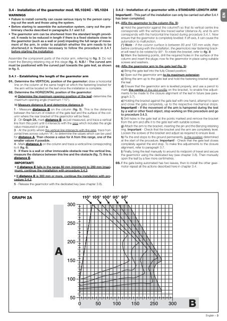
2 - On Graph 2A, mark distance B, as just measured, and trace a vertical<br />
line from this point until it intersects with the area which includes the angle<br />
value measured in point a.<br />
3 - At the points where the vertical line intersects with the area, trace horizontal<br />
lines across column “A”, to determine the values which can be used<br />
for distance A. Then choose a value for A from this range, one of the<br />
smaller values if possible.<br />
4 - Mark distance A on the column and trace a vertical line corresponding<br />
to it (fig. 6).<br />
5 - If there is a wall or other immovable obstacle near the vertical line,<br />
measure the distance between this line and the obstacle (fig. 7): this is<br />
distance E.<br />
IMPORTANT!<br />
If distance E falls in the range 80 mm (minimum) to 299 mm (maximum),<br />
continue the installation with procedure 3.4.3.<br />
If distance E is 300 mm or more, continue the installation with procedure<br />
3.4.2.<br />
5 - Release the gearmotor with the dedicated key (see chapter 3.8).<br />
GRAPH 2A<br />
3.4.2 - Installation of a gearmotor with a STANDARD LENGTH ARM<br />
Important! - This part of the installation can only be carried out after 3.4.1<br />
has been completed.<br />
01. Affix the gearmotor to the column (fig. 9):<br />
a) Hold the gearmotor against the column(*) so that its vertical centre line<br />
corresponds with the vertical line traced earlier (distance A), and its arm<br />
corresponds with the horizontal line traced during procedure 3.4.1. Now<br />
ensure that the gearmotor is completely levelled: if off-axis, it can cause the<br />
automation to malfunction.<br />
(*) Note - If the column surface is between 80 and 135 mm wide, then<br />
before continuing with the installation, the gearmotors rear fastening bracket<br />
will need to be rotated by 90°. To rotate the bracket, refer to fig. 8.<br />
b) Mark the fastening points, drill the required holes in the surface of the<br />
column and insert the plugs; now fix the gearmotor in place using suitable<br />
screws and washers.<br />
02. Affix the gearmotor arm to the gate leaf (fig. 9):<br />
a) Bring the gate leaf into the fully Closed position;<br />
b) Open out the gearmotor arm to its maximum extension;<br />
c) Bring the arm up to the gate leaf and hold the fastening bracket against<br />
the leaf.<br />
d) Ensure that the gearmotor arm is levelled properly, and use a pencil to<br />
mark the centre of the slot profile on the bracket, to enable fine adjustments<br />
to be made to the closure alignment of the leaf in future (see paragraph<br />
3.7).<br />
e) Holding the bracket against the gate leaf with one hand, attempt to open<br />
and close the gate completely, up to the respective mechanical stops.<br />
Important! - If the movement of the arm is hampered during the test<br />
by a wall or other fixed object, stop working on this procedure and go<br />
to procedure 3.4.3.<br />
f) Drill holes in the gate leaf at the points marked and remove the bracket<br />
from the arm and affix it to the gate leaf with suitable screws.<br />
g) Attach the arm to the bracket, inserting the pin and the Benzing retaining<br />
ring. Important - Check that the bracket and the arm are completely level.<br />
Loosen the screws of the bracket and adjust as required to ensure level.<br />
h) Fix the end stops to the ground permanently, in the position determined<br />
at the start of the procedure. Important! - Check that the gate leaf closes<br />
completely against the end stop. To make fine adjustments to the closure<br />
alignment, refer to paragraph 3.7.<br />
i) Finally, bring the leaf manually to around its midpoint of travel and secure<br />
the gearmotor using the dedicated key (see chapter 3.8). Then manually<br />
open the leaf by a few more centimetres.<br />
03. If the gate being automated has two leaves, then to install the other gearmotor<br />
repeat all the actions described here in chapter 3.4.<br />
English – 3<br />
EN