ISTWLR01.4865 Rev00 WALKY:Layout 1 - Fast Access Security Corp.
ISTWLR01.4865 Rev00 WALKY:Layout 1 - Fast Access Security Corp.
ISTWLR01.4865 Rev00 WALKY:Layout 1 - Fast Access Security Corp.

Create successful ePaper yourself
Turn your PDF publications into a flip-book with our unique Google optimized e-Paper software.
EN<br />
3.4.3 - Installation of a gearmotor with a SHORTENED ARM<br />
Important! - This part of the installation can only be carried out after 3.4.1<br />
has been completed.<br />
01. Determine a new maximum opening angle for the gate leaf (max 90°):<br />
ignoring the maximum opening position established for the leaf during procedure<br />
3.4.1, bring the leaf to a new maximum opening position, ensuring<br />
that the angle does not exceed 90°. Then hold the gate leaf provisionally in<br />
this position using a ground-mounted stop.<br />
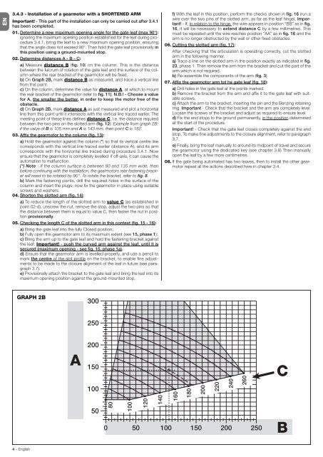
02. Determine distances A - B - C:<br />
a) Measure distance B (fig. 10) on the column. This is the distance<br />
between the fulcrum of rotation of the gate leaf and the surface of the column<br />
where the rear bracket of the gearmotor will be fixed.<br />
b) On Graph 2B, mark distance B as measured, and trace a vertical line<br />
from this point.<br />
c) On the column, determine the value for distance A, at which to mount<br />
the rear bracket of the gearmotor (refer to fig. 11). N.B.! - Choose a value<br />
for A, the smaller the better, in order to keep the motor free of the<br />
obstacle.<br />
d) On Graph 2B, mark distance A as just measured and plot a horizontal<br />
line from this point until it intersects with the vertical line traced earlier. The<br />
meeting point of these lines defines distance C, i.e. the distance required<br />
between the two pins on the slotted arm (fig. 12). Example from graph 2B:<br />
if the value of B is 105 mm and A is 143 mm, then point C is 182.<br />
03. Affix the gearmotor to the column (fig. 13):<br />
a) Hold the gearmotor against the column (*) so that its vertical centre line<br />
corresponds with the vertical line traced earlier (distance A), and its arm<br />
corresponds with the horizontal line traced during procedure 3.4.1. Now<br />
ensure that the gearmotor is completely levelled: if off-axis, it can cause the<br />
automation to malfunction.<br />
(*) Note - If the column surface is between 80 and 135 mm wide, then<br />
before continuing with the installation, the gearmotors rear fastening bracket<br />
will need to be rotated by 90°. To rotate the bracket, refer to fig. 8.<br />
b) Mark the fastening points, drill the required holes in the surface of the<br />
column and insert the plugs; now fix the gearmotor in place using suitable<br />
screws and washers.<br />
04. Shorten the slotted arm (fig. 14):<br />
a) To reduce the length of the slotted arm to value C (as established in<br />
point 02-d), unscrew the nut, remove the stop, adjust the two pins so that<br />
the distance between them is equal to value C, then fasten the nut in position<br />
provisionally.<br />
05. Checking the length C of the slotted arm in this context (fig. 15 - 16):<br />
a) Bring the gate leaf into the fully Closed position;<br />
b) Fully open the gearmotor arm to its maximum extent (see 15, phase 1);<br />
c) Bring the arm up to the gate leaf and hold the fastening bracket against<br />
the leaf: Important! - push the curved arm against the leaf, until it is<br />
secured (maximum opening - see fig. 15, phase 1a).<br />
d) Ensure that the gearmotor arm is levelled properly, and use a pencil to<br />
mark the centre of the slot profile on the bracket, to enable fine adjustments<br />
to be made to the closure alignment of the leaf in future (see paragraph<br />
3.7).<br />
e) Provisionally attach the bracket to the gate leaf and bring the leaf into its<br />
maximum opening position against the ground-mounted stop.<br />
GRAPH 2B<br />
4 – English<br />
f) With the leaf in this position, perform the checks shown in fig. 16 (run a<br />
wire over the two pins of the slotted arm, as far as the leaf hinge). Important!<br />
- If, in relation to the hinge, the wire appears in position “BB” as in fig.<br />
16, it will be necessary to extend distance C by a few millimetres. This<br />
must be repeated until the wire reaches position “AA” as in fig. 16 and the<br />
arm is no longer obstructed by the wall or other fixed obstacles.<br />
06. Cutting the slotted arm (fig. 17):<br />
After checking that the articulation is operating correctly, cut the slotted<br />
arm in the following manner.<br />
a) Trace a line on the slotted arm in the position exactly as indicated in fig.<br />
23, phase 1. Then remove the arm from the bracket and cut the part of the<br />
arm which is not required.<br />
b) Re-assemble the components of the arm (fig. 3).<br />
07. Affix the gearmotor arm tot he gate leaf (fig. 18):<br />
a) Drill holes in the gate leaf at the points marked.<br />
b) Remove the bracket from the arm and affix it to the gate leaf with suitable<br />
screws.<br />
c) Attach the arm to the bracket, inserting the pin and the Benzing retaining<br />
ring. Important - Check that the bracket and the arm are completely level.<br />
Loosen the screws of the bracket and adjust as required to ensure level.<br />
d) Fix the end stops to the ground permanently, in the position determined<br />
at the start of the procedure.<br />
Important! - Check that the gate leaf closes completely against the end<br />
stop. To make fine adjustments to the closure alignment, refer to paragraph<br />
3.7.<br />
e) Finally, bring the leaf manually to around its midpoint of travel and secure<br />
the gearmotor using the dedicated key (see chapter 3.8) Then manually<br />
open the leaf by a few more centimetres.<br />
08. If the gate being automated has two leaves, then to install the other gearmotor<br />
repeat all the actions described here in chapter 3.4.