ISTWLR01.4865 Rev00 WALKY:Layout 1 - Fast Access Security Corp.
ISTWLR01.4865 Rev00 WALKY:Layout 1 - Fast Access Security Corp.
ISTWLR01.4865 Rev00 WALKY:Layout 1 - Fast Access Security Corp.

Create successful ePaper yourself
Turn your PDF publications into a flip-book with our unique Google optimized e-Paper software.
EN<br />
control unit on terminals “P.P. (positive)” and “STOP (negative)” (fig. 26). The<br />
supply voltage varies from 18 to 31 VDC when mains or solemyo operated and<br />
from 11 to approx. 14 VDC when operating on back-up battery PS424. The<br />
maximum available current is 200 mA.<br />
Note – The voltage available in terminals “P.P.” and “STOP” remains present<br />
even when the “Stand By” function is activated on the board.<br />
4.5 - Addressing the connected devices<br />
To allow the control unit to recognise the devices connected to the Bluebus<br />
system, these devices need to be addressed. This must be done by correctly<br />
positioning the electric jumper of each device, referring to the respective<br />
instruction manual of each individual device.<br />
4.6 - Initialisation and connection check<br />
Once you have powered the control unit, carry out the following checks:<br />
after a few seconds, check that the “Bluebus” LED (fig. 26) flashes regularly<br />
at a frequency of 1 flash per second;<br />
check that the LEDs of the photocells, both TX and RX, emit flashes. The type<br />
of flashing emitted, at this stage, is not significant;<br />
check that the WLT multi-purpose lamp is turned off (set on flashing function)<br />
and connected to the FLASH output on the power supply.<br />
If this does not happen, cut off the electricity supply to the control unit and<br />
check the various electrical connections previously carried out.<br />
4.7 - Recognition of the connected devices<br />
Once initialisation is complete, the control unit must recognise the devices connected<br />
to the “Bluebus” and “Stop” inputs.<br />
IMPORTANT! – The recognition phase must be carried out even if the<br />
control unit is not connected to any devices.<br />
The control unit is designed to recognise individually the various devices connected<br />
to it thanks to the recognition procedure and it can also detect with a<br />
very high degree of precision any possible problems. Consequently, the recognition<br />
of devices must be carried out each time a device is connected or<br />
removed.<br />
LEDs “L1” and “L2” on the control unit (fig. 26) emit slow flashes to indicate<br />
that recognition needs to be carried out:<br />
01. Press and keep pressed keys “⊳” and “Set” (fig. 26) simultaneously.<br />
02. Release the keys when LEDs “L1” and “L2” begin to flash quickly (after<br />
approximately 3 seconds).<br />
03. Wait a few seconds for the control unit to complete the device recognition<br />
phase.<br />
04. At the end of this phase, the “Stop” LED should be turned on and LEDs<br />
“L1” and “L2” should turn off (LEDs “L3” and “L4” may start to flash).<br />
4.8 - Recognition of the positions of the mechanical stops<br />
After the recognition of devices (paragraph 4.7), the control unit must recognise<br />
the positions of the mechanical stops (maximum Opening and maximum Closure);<br />
During this phase, the angle of aperture of the leaf is detected from the closing<br />
mechanical stop to the opening mechanical stop. It is vital that the mechanical<br />
stops are fixed and sufficiently sturdy.<br />
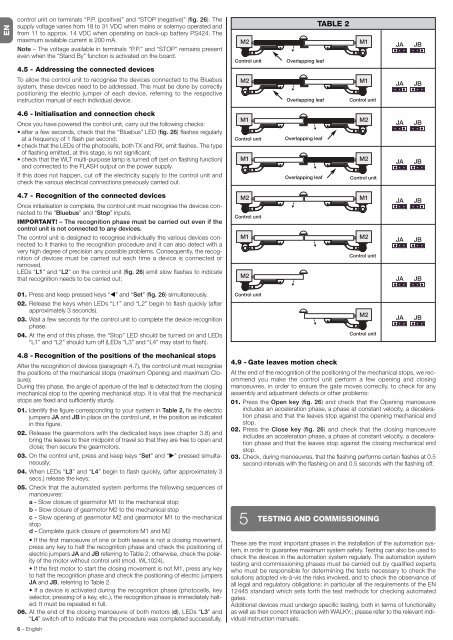
01. Identify the figure corresponding to your system in Table 2, fix the electric<br />
jumpers JA and JB in place on the control unit, in the position as indicated<br />
in this figure.<br />
02. Release the gearmotors with the dedicated keys (see chapter 3.8) and<br />
bring the leaves to their midpoint of travel so that they are free to open and<br />
close; then secure the gearmotors.<br />
03. On the control unit, press and keep keys “Set” and “” pressed simultaneously;<br />
04. When LEDs “L3” and “L4” begin to flash quickly, (after approximately 3<br />
secs.) release the keys;<br />
05. Check that the automated system performs the following sequences of<br />
manoeuvres:<br />
a - Slow closure of gearmotor M1 to the mechanical stop<br />
b - Slow closure of gearmotor M2 to the mechanical stop<br />
c - Slow opening of gearmotor M2 and gearmotor M1 to the mechanical<br />
stop<br />
d - Complete quick closure of gearmotors M1 and M2<br />
If the first manoeuvre of one or both leaves is not a closing movement,<br />
press any key to halt the recognition phase and check the positioning of<br />
electric jumpers JA and JB referring to Table 2; otherwise, check the polarity<br />
of the motor without control unit (mod. WL1024).<br />
If the first motor to start the closing movement is not M1, press any key<br />
to halt the recognition phase and check the positioning of electric jumpers<br />
JA and JB, referring to Table 2.<br />
If a device is activated during the recognition phase (photocells, key<br />
selector, pressing of a key, etc.), the recognition phase is immediately halted.<br />
It must be repeated in full.<br />
06. At the end of the closing manoeuvre of both motors (d), LEDs “L3” and<br />
“L4” switch off to indicate that the procedure was completed successfully.<br />
6 – English<br />
Control unit<br />
Control unit<br />
Control unit<br />
Control unit<br />
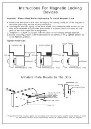
4.9 - Gate leaves motion check<br />
At the end of the recognition of the positioning of the mechanical stops, we recommend<br />
you make the control unit perform a few opening and closing<br />
manoeuvres, in order to ensure the gate moves correctly, to check for any<br />
assembly and adjustment defects or other problems:<br />
01. Press the Open key (fig. 26) and check that the Opening manoeuvre<br />
includes an acceleration phase, a phase at constant velocity, a deceleration<br />
phase and that the leaves stop against the opening mechanical end<br />
stop.<br />
02. Press the Close key (fig. 26) and check that the closing manoeuvre<br />
includes an acceleration phase, a phase at constant velocity, a deceleration<br />
phase and that the leaves stop against the closing mechanical end<br />
stop.<br />
03. Check, during manoeuvres, that the flashing performs certain flashes at 0.5<br />
second intervals with the flashing on and 0.5 seconds with the flashing off.<br />
5<br />
Overlapping leaf<br />
Overlapping leaf<br />
Overlapping leaf<br />
Overlapping leaf<br />
TABLE 2<br />
Control unit<br />
Control unit<br />
Control unit<br />
Control unit<br />
TESTING AND COMMISSIONING<br />
These are the most important phases in the installation of the automation system,<br />
in order to guarantee maximum system safety. Testing can also be used to<br />
check the devices in the automation system regularly. The automation system<br />
testing and commissioning phases must be carried out by qualified experts<br />
who must be responsible for determining the tests necessary to check the<br />
solutions adopted vis-à-vis the risks involved, and to check the observance of<br />
all legal and regulatory obligations: in particular all the requirements of the EN<br />
12445 standard which sets forth the test methods for checking automated<br />
gates.<br />
Additional devices must undergo specific testing, both in terms of functionality<br />
as well as their correct interaction with <strong>WALKY</strong>.; please refer to the relevant individual<br />
instruction manuals.