ISTWLR01.4865 Rev00 WALKY:Layout 1 - Fast Access Security Corp.
ISTWLR01.4865 Rev00 WALKY:Layout 1 - Fast Access Security Corp.
ISTWLR01.4865 Rev00 WALKY:Layout 1 - Fast Access Security Corp.

Create successful ePaper yourself
Turn your PDF publications into a flip-book with our unique Google optimized e-Paper software.
EN<br />
Other available accessories include the receivers designed with “SM” connectors<br />
(SMXI, OXI, etc.).<br />
The gearmotor with control unit (mod. WL1024C) is designed to accommodate<br />
the installation of the multi-purpose lamp mod. WLT (see chapter 3.5), which<br />
can operate as a flashing emergency light or courtesy light, depending on the<br />
control unit programming. In addition, it can be used as a twilight by activating<br />
a built-in light sensor; please refer to the relevant instruction manual for specifications.<br />
3<br />
3.1 - Pre-installation checks<br />
Before going ahead with the installation, check the integrity of the product components,<br />
and ensure the model chosen is suitable for its intended use and for<br />
the environment in which it is to be installed.<br />
Check that all the material to be used is in excellent condition and suitable for<br />
its intended use.<br />
Check that the ground-mounted mechanical stops are present both when<br />
opening and closing the automation system.<br />
Check that the mechanical structure of the gate is suitable for the installation<br />
of automation and compliant with locally applicable regulations (if necessary,<br />
refer to the label on the gate). This product cannot be used to automate a<br />
gate which is not already in good, safe working order, neither can it fix faults<br />
caused by incorrect installation or poor maintenance of the gate.<br />
Check that the operating conditions of the devices are compatible with the<br />
usage limitation declared (see paragraph 3.2).<br />
Move the gate leaves manually in both directions and ensure that the resistance<br />
to movement is constant at all points of travel (there should not be any<br />
points where more force or less is required).<br />
Bring the gate leaves manually into a position at random, then let go and<br />
check that they remain stationary.<br />
Check that the gearmotor fixing zone is compatible with its overall dimensions<br />
(fig. 1).<br />
Check that the place where the gearmotor is to be installed allows enough<br />
space for its arm to execute its full range of movement.<br />
Check that there is sufficient room around the gearmotor for it to be released<br />
manually when required.<br />
Ensure that the surfaces on which the various devices are to be installed are<br />
strong and capable of ensuring a firm hold.<br />
Ensure that each device is installed in a position which is protected and does<br />
not expose it to accidental impacts.<br />
Ensure that all the electrical cables to be used are the type listed in Table 1.<br />
3.2 - Usage limitation<br />
Before installing the gearmotor, check that its data complies with the usage limitation<br />
specified below and falls within the limits stated in the chapter entitled<br />
“Product technical specifications”:<br />
With FULL LENGTH motor arm (as shipped from the factory):<br />
- maximum width of leaf: 1.60 m (= maximum weight of leaf: 110 kg)<br />
- maximum height of leaf: 2 m<br />
With SHORTENED motor arm (cut by the installer):<br />
- maximum width of leaf: 1.60 m (= maximum weight of leaf: 100 kg)<br />
- maximum height of leaf: 2 m<br />
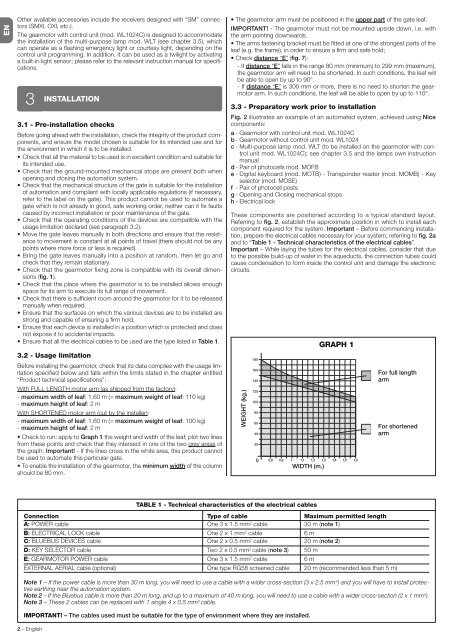
Check to run: apply to Graph 1 the weight and width of the leaf; plot two lines<br />
from these points and check that they intersect in one of the two grey areas of<br />
the graph. Important! - If the lines cross in the white area, this product cannot<br />
be used to automate this particular gate.<br />
To enable the installation of the gearmotor, the minimum width of the column<br />
should be 80 mm.<br />
2 – English<br />
INSTALLATION<br />
TABLE 1 - Technical characteristics of the electrical cables<br />
The gearmotor arm must be positioned in the upper part of the gate leaf.<br />
IMPORTANT! - The gearmotor must not be mounted upside down, i.e. with<br />
the arm pointing downwards.<br />
The arms fastening bracket must be fitted at one of the strongest parts of the<br />
leaf (e.g. the frame), in order to ensure a firm and safe hold;<br />
Check distance “E” (fig. 7):<br />
- If distance “E” falls in the range 80 mm (minimum) to 299 mm (maximum),<br />
the gearmotor arm will need to be shortened. In such conditions, the leaf will<br />
be able to open by up to 90°.<br />
- If distance “E” is 300 mm or more, there is no need to shorten the gearmotor<br />
arm. In such conditions, the leaf will be able to open by up to 110°.<br />
3.3 - Preparatory work prior to installation<br />
Fig. 2 illustrates an example of an automated system, achieved using Nice<br />
components:<br />
a - Gearmotor with control unit mod. WL1024C<br />
b - Gearmotor without control unit mod. WL1024<br />
c - Multi-purpose lamp mod. WLT (to be installed on the gearmotor with control<br />
unit mod. WL1024C); see chapter 3.5 and the lamps own instruction<br />
manual<br />
d - Pair of photocells mod. MOFB<br />
e - Digital keyboard (mod. MOTB) - Transponder reader (mod. MOMB) - Key<br />
selector (mod. MOSE)<br />
f - Pair of photocell posts<br />
g - Opening and Closing mechanical stops<br />
h - Electrical lock<br />
These components are positioned according to a typical standard layout.<br />
Referring to fig. 2, establish the approximate position in which to install each<br />
component required for the system. Important – Before commencing installation,<br />
prepare the electrical cables necessary for your system, referring to fig. 2a<br />
and to “Table 1 - Technical characteristics of the electrical cables”.<br />
Important – While laying the tubes for the electrical cables, consider that due<br />
to the possible build-up of water in the aqueducts, the connection tubes could<br />
cause condensation to form inside the control unit and damage the electronic<br />
circuits.<br />
Connection Type of cable Maximum permitted length<br />
A: POWER cable One 3 x 1.5 mm2 cable 30 m (note 1)<br />
B: ELECTRICAL LOCK cable One 2 x 1 mm2 cable 6 m<br />
C: BLUEBUS DEVICES cable One 2 x 0.5 mm2 cable 20 m (note 2)<br />
D: KEY SELECTOR cable Two 2 x 0.5 mm2 cable (note 3) 50 m<br />
E: GEARMOTOR POWER cable One 3 x 1.5 mm2 cable 6 m<br />
EXTERNAL AERIAL cable (optional) One type RG58 screened cable 20 m (recommended less than 5 m)<br />
Note 1 – If the power cable is more than 30 m long, you will need to use a cable with a wider cross-section (3 x 2.5 mm 2 ) and you will have to install protective<br />
earthing near the automation system.<br />
Note 2 – If the Bluebus cable is more than 20 m long, and up to a maximum of 40 m long, you will need to use a cable with a wider cross-section (2 x 1 mm 2 ).<br />
Note 3 – These 2 cables can be replaced with 1 single 4 x 0.5 mm 2 cable.<br />
IMPORTANT! – The cables used must be suitable for the type of environment where they are installed.<br />
WEIGHT (kg.)<br />
WIDTH (m.)<br />
GRAPH 1<br />
For full length<br />
arm<br />
For shortened<br />
arm