ISTWLR01.4865 Rev00 WALKY:Layout 1 - Fast Access Security Corp.
ISTWLR01.4865 Rev00 WALKY:Layout 1 - Fast Access Security Corp.
ISTWLR01.4865 Rev00 WALKY:Layout 1 - Fast Access Security Corp.

Create successful ePaper yourself
Turn your PDF publications into a flip-book with our unique Google optimized e-Paper software.
3.5 - Installation of the multi-purpose lamp mod. WLT on the<br />
gearmotor model WL1024C<br />
Warning – WLT can operate as a flashing emergency light or courtesy light,<br />
depending on the control unit programming.<br />
Follow the installation steps shown in fig. 21, making sure the right sequence is<br />
followed and the following warnings are adhered to:<br />
for stage 4 – Rotate the power unit in the direction of the arrow, keeping a<br />
careful eye on the cables underneath that connect it to the gearmotor.<br />
for stage 7 – Open out the cables fully and insert the connector into the<br />
FLASH output as shown; secure the cables by inserting them in the cable<br />
gland.<br />
for stage 11 – Position the electrical board on the pin of the base, depending<br />
on the desired usage: A = diffuse light; B = directional light beam (in this case,<br />
the light beam can be directed by blocking the board in one of the holes on the<br />
base).<br />
for stage 12 – Open out the cable fully, cut the excess portion and position<br />
the cables in such a way that they do not cast any shadows over the LEDs and<br />
the light sensor fitted on the back of the electrical board.<br />
for stage 13 – The arrow on the cover and the one on the base should align.<br />
Ensure the 4 cogs on the base fit into the grooves inside the cover.<br />
3.6 - How to remove the control unit<br />
01. Remove the gearmotors lower cover (fig. 19);<br />
02. Undo the 4 screws of the cable sleeve support and remove it (fig. 24,<br />
phase 1-2);<br />
03. Pull the control unit about 4 centimetres in the direction of the arrow, and<br />
detach the motor connector (fig. 24, phase 3-4);<br />
04. Finally, remove the control unit completely;<br />
Important! - When reconnecting the motor to the control unit, observe the<br />
polarity of the connector (this can only be inserted one way around!).<br />
3.7 - Adjusting the alignment of the gate leaves when closed<br />
01. Remove the slotted arm from the fastening bracket on the gate leaf;<br />
02. Loosen the screws on the bracket and move it by a few millimetres towards<br />
the gearmotor;<br />
03. Then replace the slotted arm in the bracket, close the leaf and check that it<br />
is both aligned with the other leaf and in contact with the end stop. Important!<br />
- If necessary, repeat point 02 until an optimum alignment is achieved;<br />
04. Drill a hole in the leaf, to correspond to the hole in the centre of the fastening<br />
bracket, and insert a screw. Then fix the bracket permanently in place<br />
by tightening the three screws;<br />
05. Finally, attach the slotted arm to the bracket, inserting the pin and the Benzing<br />
retaining ring.<br />
3.8 - Securing and releasing the gearmotor manually<br />
The gearmotor is equipped with a mechanical system which allows the gate to<br />
be opened and closed manually.<br />
These manual operations are required in the event of power cuts, operational<br />
faults, or during installation.<br />
Releasing (fig. 22-A):<br />
01. Rotate the release disc clockwise by 90°;<br />
02. Insert the key into the release pin;<br />
03. Turn the key by almost a full turn clockwise.<br />
04. Remove the key from the pin and rotate the release disc anticlockwise by<br />
90° so that the hole is blocked.<br />
05. The gate leaf can now be moved manually into the required position.<br />
Securing (fig. 22-B):<br />
01. Turn the key anticlockwise in the release pin and move the gate leaf manually<br />
until you can hear the leaf engage mechanically with the drive mechanism.<br />
02. Remove the key from the pin and rotate the release disc anticlockwise by<br />
90° so that the hole is blocked.<br />
4<br />
ELECTRICAL CONNECTIONS<br />
The electrical connection of the various devices (photocells, digital keyboards,<br />
transponder card readers, etc.) of the automation system with a control unit is<br />
carried out with the Nice “Bluebus” system. This system makes it possible to<br />
carry out the electrical connections with the use of just 2 wires along which<br />
both the electricity supply and the communication signals travel. The electrical<br />
connection to be used is parallel and does not require any polarity to be<br />
observed. During the recognition phase, every device connected to the control<br />
unit will be recognised individually by the latter, thanks to a univocal code. Every<br />
time a device is added or removed, you must carry out the control unit recognition<br />
phase (see paragraph 4.7).<br />
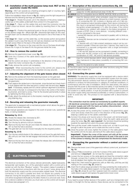
4.1 - Description of the electrical connections (fig. 23)<br />
M1 gearmotor output 1<br />
ELS output for 12 VAC electrical lock (max 15 VA). [*]<br />
BLUEBUS input for compatible devices (MOFB, MOFOB, MOB and MOTB)<br />
STOP input for devices which, when activated, cause the manoeuvre in<br />
progress to halt immediately, followed by a brief inversion; possibility<br />
of connecting NO, NC contacts or devices with a 8.2 kΩ constant<br />
resistance output (sensitive edges). Each device connected to<br />
this input is recognised individually by the control unit during the<br />
recognition phase (paragraph 4.7); after this phase, if the control<br />
unit detects any variation with respect to the status recognised, it<br />
causes a STOP. One or more devices - including different ones -<br />
can be connected to this input:<br />
– several NO devices can be connected in parallel, with no limits as<br />
to quantity;<br />
– several NC devices can be connected in parallel, with no limits as<br />
to quantity;<br />
– 2 devices with a 8.2 kΩ constant resistance output can be connected<br />
in parallel. If there are more than 2 devices, they need to be<br />
connected in a cascade configuration with a single termination<br />
resistance of 8.2 kΩ;<br />
– 2 NO and NC devices can be connected in parallel, connecting in<br />
series with the NC contact a 8.2 kΩ resistance (this makes the<br />
combination of 3 NO - NC and 8.2 kΩ devices possible)<br />
P.P. input for control devices which, when activated, cause the Stepstep<br />
manoeuvre to take place; possibility of connecting NO contacts<br />
AERIAL input for the aerial of a radio receiver<br />
[*] The ELS output can be programmed with other functions using the Oview<br />
programmer (see chapter 8.3).<br />
4.2 - Connecting the power cable<br />
WARNING: The electricity supply line must be equipped with a device which<br />
ensures the complete disconnection of the automation system from the mains.<br />
The disconnection devices contacts must have an opening distance which is<br />
sufficient to achieve full disconnection in category III overload conditions, in<br />
conformance with the rules of installation. When the need arises, this device<br />
ensures that the power is disconnected quickly and safely; it must therefore be<br />
positioned where it can be seen from the automation system. If, however, it is<br />
not located in a visible position, it must be provided with a system to prevent<br />
the power supply being reconnected accidentally or without authorisation, in<br />
order to avoid any risk. The product is not supplied with a disconnection<br />
device.<br />
IMPORTANT!<br />
– The connection must be carried out exclusively by qualified experts.<br />
– All electrical connections must be carried out without any mains electrical<br />
power supply and with the back-up battery disconnected - where<br />
present in the automation system.<br />
01. <strong>Access</strong> the power unit by undoing the 3 screws in the gearmotors upper<br />
cover and slowly rotate the cover in the direction of the arrow (fig. 24),<br />
keeping a careful eye on the cables underneath;<br />
02. Connect the phase and neutral wires to the power unit terminal board,<br />
observing the instructions on the label; close the earth cable grommet<br />
using the screw (fig. 25): care required! -the terminal should be pointing<br />
towards the opening from which the power cable emerges;<br />
03. Then pull the power cable towards the control unit, so that it is just long<br />
enough to allow the power unit to rotate and the cover to close;<br />
04. Close the power unit cover; tighten the screws on the cable gland; insert<br />
the control unit into its seat, and remount the cable sleeve support;<br />
Important! - <strong>Fast</strong>en the cover of the power unit with all the screws<br />
and ensure that the seal is well positioned in its seat. If the seal or one<br />
of the screws is missing, this can compromise the electronics inside.<br />
4.3 - Connecting the gearmotor without a control unit mod.<br />
WL1024<br />
01. Remove the lower cover of the gearmotor without control unit, as shown in<br />
fig. 19;<br />
02. Using a Phillips screwdriver, undo the 4 screws of the cable sleeve support<br />
and remove it (important! - do not lose the 2 spacers).<br />
03. Loosen the two screws on the cable gland and feed the connection cable<br />
through; connect the 3 cables to the terminal board, observing the symbols<br />
as labelled; then tighten the screws of the cable gland.<br />
04. Adjust the 2 feet inside the gearmotor with an Allen key, until they are fully<br />
resting on the column (fig. 20, phase 5).<br />
05. Insert the 6 rubber plugs (provided in the bag containing the small parts) in<br />
the holes in the cable sleeve support; cut the edge of the cable sleeve support<br />
(fig. 20, phase 6); put the 2 spacers back into position; remount the<br />
cable sleeve support and replace the gearmotors lower cover.<br />
4.4 - Connecting other devices<br />
If you need to power further devices in the system, such as a transponder card<br />
reader or the light for the key selector, these devices can be connected to the<br />
English – 5<br />
EN