ISTWLR01.4865 Rev00 WALKY:Layout 1 - Fast Access Security Corp.
ISTWLR01.4865 Rev00 WALKY:Layout 1 - Fast Access Security Corp.
ISTWLR01.4865 Rev00 WALKY:Layout 1 - Fast Access Security Corp.

You also want an ePaper? Increase the reach of your titles
YUMPU automatically turns print PDFs into web optimized ePapers that Google loves.
7<br />
WHAT TO DO IF... (troubleshooting guide)<br />
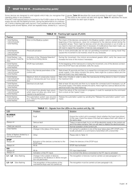
Some devices are designed to emit signals which help you recognise their<br />
operating status or any problems.<br />
If the WLT multi-purpose lamp is connected to the FLASH output on the power<br />
supply and set with the flashing function, during the performance of a manoeuvre,<br />
it emits a flashing light every second. If any problems are encountered, the<br />
flashing emits shorter flashes, which are repeated twice, divided by a 1 second<br />
Flashes Problem Solution<br />
1 brief flashing<br />
1 second pause<br />
1 brief flashing<br />
2 brief flashes<br />
1 second pause<br />
2 brief flashes<br />
3 brief flashes 1-second<br />
pause 3 brief flashes<br />
4 brief flashes<br />
1 second pause<br />
4 brief flashes<br />
5 brief flashes<br />
1 second pause<br />
5 brief flashes<br />
6 brief flashes<br />
1 second pause<br />
6 brief flashes<br />
7 brief flashes<br />
1 second pause<br />
7 brief flashes<br />
8 brief flashes<br />
1 second pause<br />
8 brief flashes<br />
9 brief flashes<br />
1 second pause<br />
9 brief flashes<br />
pause. Table 10 describes the cause and solution for each type of signal.<br />
The LEDs on the control unit also emit signals; Table 11 describes the cause<br />
and solution for each type of signal.<br />
Electrical circuits fault Wait at least 30 seconds and then try to repeat the command and if necessary cut off<br />
the power supply; if the status remains the same, there might be a serious failure and the<br />
electrical board may need replacing.<br />
A command has already been given,<br />
which does not allow any other commands<br />
to be performed<br />
The automation system was secured<br />
by a “Secure the automation system”<br />
command<br />
TABLE 10 - Flashing light signals (FLASH)<br />
Error on the Bluebus system The check of the devices connected to the Bluebus system, which is carried out at the<br />
beginning of the manoeuvre, does not correspond to the devices stored during the<br />
recognition phase. There might be devices which are disconnected or out of order, so<br />
you need to check and replace them if necessary. If modifications have been made, you<br />
will need to repeat the recognition of devices (see paragraph 4.7).<br />
Photocell activation One or more photocells are not are not permitting movement or during travel they<br />
caused the movement to be inverted; check for any obstacles.<br />
Activation of the “Obstacle Detection"<br />
by the force limiting device<br />
During the movement, the motors encountered greater effort; verify the cause and<br />
increase the force of the motors if necessary<br />
STOP input activation At the beginning of the manoeuvre or during the movement, one of the devices connected<br />
to the STOP input was activated; verify the cause.<br />
Error in the internal parameters of the<br />
control unit<br />
Maximum limit of consecutive ma noe -<br />
u vres or manoeuvres per hour ex ce e -<br />
ded.<br />
Wait at least 30 seconds and then try to repeat the command and if necessary cut off the<br />
power supply; if the status remains the same, there might be a serious failure and the<br />
electrical board may need replacing.<br />
Wait a few minutes in order to allow the manoeuvres limiting device to return to below<br />
the maximum limit.<br />
Check the nature of the command in progress; it could for example be the command<br />
from a clock on the “opens” input.<br />
Release the automation system by sending the “Release the automation system” command.<br />
TABLE 11 - Signals from the LEDs on the control unit (fig. 23)<br />
LED Problem Solution<br />
BLUEBUS<br />
lways off<br />
Always on<br />
1 flash per second<br />
2 fast flashes<br />
Series of flashes divided by a<br />
one-second pause<br />
STOP<br />
Always off<br />
Always on<br />
P.P.<br />
Always off<br />
Always on<br />
Fault<br />
Serious fault<br />
All ok<br />
Change in the status of the inputs<br />
Other<br />
Activation of the devices connected to the<br />
STOP input<br />
All ok<br />
L1 - L2 Slow flashing<br />
All ok<br />
Activation of the P.P. input<br />
Change in the number of devices<br />
connected to the Bluebus or device recognition<br />
not performed<br />
L3 - L4 Slow flashing The recognition of the positions of the<br />
mechanical stops was not carried out<br />
Ensure the control unit is powered; check whether the fuses have blown.<br />
In this case, check the cause of the fault and replace them with others of<br />
the same value<br />
There is a serious fault: try to cut off the electricity supply to the control unit<br />
and if the status remains, then you will need to replace the electrical board<br />
Normal operation of the control unit<br />
If it normal if a variation in one of the input takes place (PP, STOP): photocells<br />
activation or a command is transmitted with a transmitter<br />
Please refer to Table 10<br />
Check the devices of the STOP input<br />
STOP input activated<br />
P.P. input deactivated<br />
It is normal if the device connected to the P.P. input is activated<br />
The recognition of devices must be carried out (see paragraph 4.7)<br />
The recognition must be carried out (see paragraph 4.8).<br />
English – 9<br />
EN