deu Einhand-Rohrbieger eng Hand tube bender ... - Albert Roller
deu Einhand-Rohrbieger eng Hand tube bender ... - Albert Roller
deu Einhand-Rohrbieger eng Hand tube bender ... - Albert Roller

You also want an ePaper? Increase the reach of your titles
YUMPU automatically turns print PDFs into web optimized ePapers that Google loves.
<strong>Einhand</strong>-<strong>Rohrbieger</strong><br />
<strong>deu</strong><br />
<strong>eng</strong><br />
fra<br />
<strong>Einhand</strong>-<strong>Rohrbieger</strong><br />
Betriebsanleitung<br />
Vor Inbetriebnahme lesen!<br />
<strong>Hand</strong> <strong>tube</strong> <strong>bender</strong><br />
Operating Instructions<br />
Please read before commissioning!<br />
Cintreuse à main<br />
Instructions d’emploi<br />
A lire avant la mise en service!<br />
Made in Germany<br />
<strong>Albert</strong> <strong>Roller</strong> GmbH & Co KG · Werkzeug- und Maschinenfabrik<br />
Neue Rommelshauser Straße 4 · D-71332 Waiblingen · Postfach 1651 · D-71306 Waiblingen<br />
Telefon +49 7151 17 27-0 · Telefax +49 7151 17 27-87<br />
www.albert-roller.de · email: info@albert-roller.de<br />
S 07/08 153255A
<strong>deu</strong> / <strong>eng</strong> / fra<br />
3<br />
6 4 2<br />
8<br />
9 5 3 3 1 7<br />
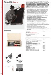
Biegesegment<br />
für Rohre<br />
Ø mm/Zoll<br />
Bending former<br />
for pipes<br />
Ø mm/inch<br />
Forme de cintrage<br />
pour <strong>tube</strong>s<br />
Ø mm/pouce<br />
Matrice<br />
per tubi<br />
Ø mm/pollici<br />
Biegeradius<br />
mm<br />
Bending<br />
radius<br />
mm<br />
Rayon de<br />
cintrage<br />
mm<br />
Raggio di<br />
curvatura<br />
mm<br />
Geeignet für / Suited for / Convient pour / Adatto per<br />
Art.-Nr.<br />
Art.-No.<br />
Code<br />
Cod.art.<br />
10, 3 /8 30 • • 153155<br />
12, 10 U, 1 /2 36 • • • 153160<br />
14, 12 U 50 • • • • 153170<br />
15, 12 U, 5 /8 55 • • • 153175<br />
16, 14 U 55 • • • • 153180<br />
17, 15 U 60 • 153185<br />
18, 14 U, 15 U, 16 U, 3 /4 72 • • • • 153190<br />
20, 18 U 79 • • • • 153195<br />
22, 18 U, 7 /8 86 • • 153200<br />
25, 26 88 • 153205<br />
32 128 • 153210<br />
Cu:<br />
St 2394-U:<br />
weiche Kupferrohre, auch dünnwandig<br />
ummantelte Stahlrohre des Pressfitting-Systems<br />
mapress C-STAHL<br />
St 2391–2394: weiche Präzisionsstahlrohre DIN 2391–2394<br />
U: ummantelt<br />
V: Verbundrohre der Pressfitting-Systeme<br />
Cu:<br />
St 2394-U:<br />
Soft copper <strong>tube</strong>s, also thin-wall<br />
Coated steel <strong>tube</strong>s of pressfitting system mapress<br />
C-STAHL<br />
St 2391–2394: Soft precision steel <strong>tube</strong>s DIN 2391–2394<br />
U: Coated <strong>tube</strong>s<br />
V: Multi-layer composite <strong>tube</strong>s of pressfitting systems<br />
Cu Cu-U St 2394-U St 2391–2394 V<br />
Cu:<br />
St 2394-U:<br />
Tubes cuivre recuit aussi à paroi mince<br />
Tubes acier enrobés du système Pressfitting<br />
mapress C-STAHL<br />
St 2391–2394: Tubes acier de précision, écroui, DIN 2391-2394<br />
U: Enrobé<br />
V: Tubes composite des systèmes Pressfitting<br />
Cu:<br />
St 2394-U:<br />
Tubi di rame cotto, anche a parete sottile<br />
Tubi d'acciaio rivestiti del sistema pressfitting<br />
mapress C-STAHL<br />
St 2391–2394: Tubi d'acciaio di precisione DIN 2391-2394, cotto<br />
U: Rivestiti<br />
V: Tubi composti dei sistemi Pressfitting
<strong>deu</strong><br />
Vor Inbetriebnahme lesen!<br />
Das Gerät ist nach dem Stand der Technik und den anerkannten sicherheitstechnischen<br />
Regeln gebaut und betriebssicher. Dennoch können bei unsachgemäßer<br />
oder nicht bestimmungsgemäßer Verwendung Gefahren für<br />
den Benutzer oder Dritte bzw. Sachbeschädigungen entstehen. Deshalb Sicherheitshinweise<br />
lesen und beachten!<br />
Grundsätzliche Sicherheitshinweise<br />
• Gerät nur bestimmungsgemäß und unter Beachtung der allgemeinen<br />
Sicherheits- und Unfallverhütungsvorschriften verwenden.<br />
• Nur unterwiesenes Personal einsetzen. Jugendliche dürfen Gerät nur<br />
betreiben, wenn sie über 16 Jahre alt sind, dies zur Erreichung ihres<br />
Ausbildungszieles erforderlich ist und sie unter Aufsicht eines Fachkundigen<br />
gestellt sind.<br />
• Arbeitsplatz in Ordnung halten. Unordnung birgt Unfallgefahr.<br />
• Gerät nicht dem Regen aussetzen, nicht in feuchter oder nasser Umgebung<br />
benutzen. Gerät trocken und sicher lagern.<br />
• Für gute Beleuchtung am Arbeitsplatz sorgen.<br />
• Enganliegende Arbeitskleidung tragen, lose hängende Haare schützen,<br />
<strong>Hand</strong>schuhe, Schmuckstücke und ähnliches ablegen.<br />
• Persönliche Schutzausrüstung benutzen (z. B. Schutzbrille, Gehörschutz).<br />
• Andere Personen, insbesondere Kinder, fernhalten.<br />
• Nicht in sich bewegende (umlaufende) Teile greifen.<br />
• Auf gute Standposition während des Arbeitens achten.<br />
• Gerät von Zeit zu Zeit auf Beschädigungen und bestimmungsgemäße<br />
Funktion überprüfen.<br />
• Verschlissene Teile umgehend auswechseln.<br />
• Zur persönlichen Sicherheit, zur Sicherung der bestimmungsgemäßen<br />
Funktion des Gerätes, und zur Erhaltung des Gewährleistungsanspruches<br />
nur Originalzubehör und Originalersatzteile verwenden.<br />
• Jegliche eigenmächtige Veränderung am Gerät ist aus Sicherheitsgründen<br />
nicht gestattet.<br />
• Instandsetzungs- und Reparaturarbeiten dürfen nur von Fachkräften oder<br />
unterwiesenen Personen durchgeführt werden.<br />
1. Technische Daten<br />
1.1. Artikelnummern<br />
Biegesegmente<br />
siehe Tabelle<br />
Biegerantrieb 153100<br />
Universal-Gleitstückträger 10–26 ( 3 /8– 7 /8) 153125<br />
Gleitstückträger 32 153115<br />
Stahlblechkasten 153265<br />
Vorrichtung für Umkehrbögen an verlegten Rohren 153140<br />
1.2. Arbeitsbereich<br />
Weiche Kupferrohre<br />
Ø 10 – 22 mm<br />
Weiche, ummantelte Kupferrohre, auch dünnwandige<br />
Heizungsrohre nach DIN EN 1057<br />
Ø 10 – 18 mm<br />
ummantelte Stahlrohre des Pressfitting-Systems<br />
mapress C-STAHL<br />
Ø 12 – 18 mm<br />
Präzisionsstahlrohre DIN 2391 – 2394, weich,<br />
blank oder ummantelt<br />
Ø 10 – 18 mm<br />
Verbundrohre der Pressfitting-Systeme<br />
Ø 14 – 32 mm<br />
Harte Kupferrohre müssen durch Ausglühen weichgemacht werden!<br />
1.3. Lärminformation<br />
Arbeitsplatzbezogener Emissionswert<br />
70 dB (A)<br />
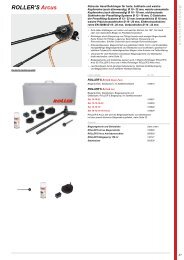
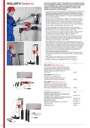
2. Inbetriebnahme<br />
Gleitstückträger (1) so auf Biegerantrieb (2) aufsetzen, dass die Gleitstücke<br />
(3) für die gewünschte Rohrgröße in Richtung zur Zahnstange (4) liegen.<br />
Die Gleitstücke sind mit der Rohrgröße gekennzeichnet. Gleitstückträger mit<br />
Flügelschraube (5) befestigen. Der Rohrgröße entsprechendes Biegesegment<br />
(6) wählen und auf Hubstange (4) aufstecken. Hebel (7) in Pfeilrichtung<br />
(8) nach unten drücken und Biegesegment (Zahnstange) bis zum hinteren<br />
Anschlag zurückschieben. Hebel (7) loslassen.<br />
3. Betrieb<br />
Gleitstücke (3) so drehen, dass der der Rohrgröße entsprechende Radius<br />
am Gleitstück auf der Seite zum Biegesegment hin liegt. Rohr zwischen Biegesegment<br />
und Gleitstück einlegen. Hebel mehrmals entgegen Pfeilrichtung<br />
(8) drücken und Biegesegment so weit wie gewünscht vortreiben. Hebel in<br />
<strong>deu</strong><br />
Pfeilrichtung (8) drücken und Biegesegment, gegebenenfalls mit gebogenem<br />
Rohr, zurückschieben. Rohr entnehmen.<br />
Auf der Oberseite der Biegesegmente (6) sind Markierungen (9) angebracht,<br />
die maßgenaues Biegen erlauben. Hierzu ist der Maßstrich, bei dem der Bogen<br />
beendet sein soll, an der Markierung (9) anzulegen.<br />
Achtung! Die Biegesegmente und die Gleitstücke sind aus glasfaserverstärktem<br />
Polyamid. Dieser Kunststoff hat besonders gute Gleiteigenschaften,<br />
ist hochfest und wärmebeständig bis ca. 150°C. Ausgeglühte Kupferrohre<br />
müssen unter diese Temperatur abgekühlt sein.<br />
4. Instandhaltung<br />
Das Gerät ist wartungsfrei und benötigt keine Instandhaltung.<br />
5. Hersteller-Garantie<br />
Die Garantiezeit beträgt 12 Monate nach Übergabe des Neuproduktes an<br />
den Erstverwender, höchstens jedoch 24 Monate nach Auslieferung an den<br />
Händler. Der Zeitpunkt der Übergabe ist durch die Einsendung der Original-Kaufunterlagen<br />
nachzuweisen, welche die Angaben des Kaufdatums<br />
und der Produktbezeichnung enthalten müssen. Alle innerhalb der Garantiezeit<br />
auftretenden Funktionsfehler, die nachweisbar auf Fertigungs- oder<br />
Materialfehler zurückzuführen sind, werden kostenlos beseitigt. Durch die<br />
Mängelbeseitigung wird die Garantiezeit für das Produkt weder verlängert<br />
noch erneuert. Schäden, die auf natürliche Abnutzung, unsachgemäße Behandlung<br />
oder Missbrauch, Missachtung von Betriebsvorschriften, ungeeignete<br />
Betriebsmittel, übermäßige Beanspruchung, zweckfremde Verwendung,<br />
eigene oder fremde Eingriffe oder andere Gründe, die ROLLER nicht<br />
zu vertreten hat, zurückzuführen sind, sind von der Garantie ausgeschlossen.<br />
Garantieleistungen dürfen nur von einer autorisierten ROLLER Vertrags-<br />
Kundendienstwerkstatt erbracht werden. Beanstandungen werden nur anerkannt,<br />
wenn das Produkt ohne vorherige Eingriffe in unzerlegtem Zustand<br />
einer autorisierten ROLLER Vertrags-Kundendienstwerkstatt eingereicht<br />
wird. Ersetzte Produkte und Teile gehen in das Eigentum von ROLLER über.<br />
Die Kosten für die Hin- und Rückfracht trägt der Verwender.<br />
Die gesetzlichen Rechte des Verwenders, insbesondere seine Mängelansprüche<br />
gegenüber dem Händler, bleiben unberührt. Diese Hersteller-<br />
Garantie gilt nur für Neuprodukte, welche in der Europäischen Union, in<br />
Norwegen oder in der Schweiz gekauft werden.<br />
6. ROLLER Vertrags-Kundendienstwerkstätten<br />
Firmeneigene Fachwerkstatt für Reparaturen:<br />
SERVICE-CENTER<br />
Neue Rommelshauser Straße 4<br />
D-71332 Waiblingen<br />
Telefon (0 7151) 5 68 08 - 60<br />
Telefax (07151) 56808-64<br />
Wir holen Ihre Maschinen und Werkzeuge bei Ihnen ab!<br />
Nutzen Sie in der Bundesrepublik Deutschland unseren Abholservice.<br />
Einfach anrufen unter Telefon (0 7151) 5 68 08 - 60.<br />
Oder wenden Sie sich an eine andere autorisierte ROLLER Vertrags-<br />
Kundendienstwerkstatt in Ihrer Nähe.<br />
7. EG-Konformitätserklärung<br />
ROLLER erklärt hiermit, dass die in dieser Betriebsanleitung beschriebenen<br />
Maschinen mit den Bestimmungen der Richtlinien 98/37/EG,<br />
89/336/EWG und 73/23/EWG konform sind. Folgende Normen werden<br />
entsprechend angewandt: DIN EN ISO 12100-1, DIN EN 12348, DIN EN<br />
50144-1, DIN EN 55014-1, DIN EN 55014-2, DIN EN 60204-1, DIN EN<br />
60335-1, DIN EN 60335-2-45, DIN EN 60745-1, DIN EN 60745-2-9, DIN<br />
EN 60745-2-11, DIN EN 61000-3-2, DIN EN 61000-3-3, DIN EN 61029-1,<br />
DIN EN 61029-2-9, DIN/ISO 3744.<br />
Waiblingen, 01.07.2008<br />
<strong>Albert</strong> ROLLER GmbH & Co KG<br />
Werkzeug- und Maschinenfabrik<br />
D-71332 Waiblingen<br />
Rainer Hech
<strong>eng</strong><br />
Please read before commissioning!<br />
The unit has been designed with the benefit of the most up-to-date technology<br />
and to recognised safety regulations, and is safe to operate. However,<br />
if it is used incorrectly or for a purpose for which it was not intended, risks to<br />
the user or to third parties or damage to property may result. For this reason,<br />
read and comply with the safety instructions!<br />
Basic Safety lnstructions<br />
• Only use the unit for the purpose for which it was intended, with due attention<br />
to the general safety and accident prevention regulations.<br />
• Only allow trained personnel to use it. Apprentices may only operate the<br />
unit when they are older than 16, when this is necessary for their training,<br />
and under the supervision of a trained operative.<br />
• Keep the work area tidy. Clutter can prove dangerous.<br />
• Do not expose the unit to rain or to damp or wet surroundings. Store the<br />
unit where it is dry and safe.<br />
• Provide adequate lighting at the workplace.<br />
• Wear suitable work clothes, keep long hair well clear, take off gloves, jewellery<br />
and similar.<br />
• Use personal safety equipment (e. g. safety glasses, ear protectors).<br />
• Keep bystanders away, especially children.<br />
• Keep hands away from moving (rotating) parts.<br />
• Take up a firm standing position during operation.<br />
• Check the unit occasionally for damage, and to see that it is operating<br />
correctly.<br />
• Replace worn parts as early as possible.<br />
• Only use genuine spare parts and accessories, for personal safety<br />
reasons, to ensure correct operation of the unit, and to preserve the<br />
basis for warranty claim.<br />
• All unauthorised modifications of the unit are prohibited for safety<br />
reasons.<br />
• All repair work must be performed only by specialist personnel or by persons<br />
familiar with the unit.<br />
1. Technical Data<br />
1.1. Article numbers<br />
Bending formers<br />
see table<br />
Bender drive 153100<br />
Universal crossbar 10–26 ( 3 /8– 7 /8) 153125<br />
Crossbar 32 153115<br />
Steel case 153265<br />
Device for reverse bends on installed pipes 153140<br />
1.2. Capacity<br />
Soft copper pipes<br />
Ø 10 – 22 mm<br />
Coated soft copper pipes, also thin-walled<br />
heating pipes according DIN EN 1057<br />
Ø 10 – 18 mm<br />
Heating pipes of mapress C-STAHL pressfitting system Ø 12 – 18 mm<br />
Precision steel pipes DIN 2391 – 2394, soft,<br />
black or plastic coated<br />
Ø 10 – 18 mm<br />
Composite pipes of pressfitting systems<br />
Ø 14 – 32 mm<br />
Hard copper pipes have to be annealed!<br />
1.3. Noise information<br />
Emission at workplace<br />
2. Setting up<br />
70 dB (A)<br />
Put the crossbar (1) on the <strong>bender</strong> unit (2), so that the sliding pieces (3) for<br />
the desired pipe size are positioned towards the dented rod (4). The sliding<br />
pieces are marked with the various pipe sizes. Fasten the crossbar with the<br />
wing screw (5). Choose the correct former (6) and put it on the ratchet bar<br />
(4). Press the feed lever (7) in indicated direction (8) downwards and push<br />
the former (ratchet bar) back towards the handle. Release feed lever (7).<br />
3. Operation<br />
<strong>eng</strong><br />
Turn the sliding pieces (3) as such, that the related radius of the indicated<br />
pipe size is positioned opposite the former. Put the pipe in between the form<br />
and sliding piece. Press feed lever a few times in indicated direction (8) and<br />
drive the former as far as desired. Push the feed lever towards indicated direction<br />
(8) and push the form if necessary with the bent pipe backwards. Take<br />
the pipe out.<br />
The upper side of the formers (6) show marks (9), which allow precision bending.<br />
To this the marking point where the bend should end has to be positioned<br />
to the marking (9).<br />
Attention! The formers and the sliding pieces are made of glass-fibre<br />
reinforced polyamide. This artificial material has a special positive sliding<br />
effect, is highly-tensile and resistant to heat up to app. 150°C. Annealed<br />
copper pipes should therefore be cooled down to below this temperature.<br />
4. Service / Repair<br />
The unit is maintenance-free, no service required.<br />
5. Manufacturer’s Warranty<br />
The warranty period shall be 12 months from delivery of the new product to<br />
the first user but shall be a maximum of 24 months after delivery to the Dealer.<br />
The date of delivery shall be documented by the submission of the original<br />
purchase documents, which must include the date of purchase and the<br />
designation of the product. All functional defects occurring within the warranty<br />
period, which clearly the consequence of defects in production or materials,<br />
will be remedied free of charge. The remedy of defects shall not extend<br />
or renew the guarantee period for the product. Damage attributable to natural<br />
wear and tear, incorrect treatment or misuse, failure to observe the operational<br />
instructions, unsuitable operating materials, excessive demand, use<br />
for unauthorized purposes, interventions by the Customer or a third party or<br />
other reasons, for which ROLLER is not responsible, shall be excluded from<br />
the warranty.<br />
Services under the warranty may only be provided by customer service stations<br />
authorized for this purpose by ROLLER. Complaints will only be accepted<br />
if the product is returned to a customer service station authorized by<br />
ROLLER without prior interference in an unassembled condition. Replaced<br />
products and parts shall become the property of ROLLER.<br />
The user shall be responsible for the cost of shipping and returning the product.<br />
The legal rights of users, in particular the right to claim damages from the<br />
Dealer, shall not be affected. This manufacturer’s warranty shall apply only<br />
to new products purchased in the European Union, in Norway or Switzerland.<br />
6. EC declaration of conformity<br />
ROLLER declares that the products decribed in this user manual comply<br />
with corresponding directives 98/37/EG, 89/336/EWG and 73/23/EWG.<br />
Correspondingly this applies to the following norms: DIN EN ISO 12100-1,<br />
DIN EN 12348, DIN EN 50144-1, DIN EN 55014-1, DIN EN 55014-2,<br />
DIN EN 60204-1, DIN EN 60335-1, DIN EN 60335-2-45, DIN EN 60745-1,<br />
DIN EN 60745-2-9, DIN EN 60745-2-11, DIN EN 61000-3-2, DIN EN<br />
61000-3-3, DIN EN 61029-1, DIN EN 61029-2-9, DIN/ISO 3744.<br />
Waiblingen, 01.07.2008<br />
<strong>Albert</strong> ROLLER GmbH & Co KG<br />
Manufacturer of Tools and Machines<br />
D-71332 Waiblingen<br />
Rainer Hech
fra<br />
A lire avant que de mettre l’appareil en service!<br />
Cet appareil a été conçu et fabriqué selon les plus récentes connaissances<br />
techniques et en tenant compte des règles de sécurité en vigueur. L’emploi<br />
abusif ou inapproprié de l’appareil peut cependant être la source de dangers<br />
aussi bien pour l’opérateur que des tiers se tenant dans son voisinage, ou<br />
causer des dégâts matériels. Pour cette raison, lire attentivement les remarques<br />
relatives à la sécurité!<br />
Remarques concernant la sécurité générale<br />
• N’utiliser l’appareil que pour accomplir les tâches pour lesquelles il a été<br />
spécialement conçu, et se conformer aux prescriptions élémentaires relatives<br />
à la Sécurité du Travail et à la Prévention d’Accidents.<br />
• L’appareil ne doit être opéré que par du personnel spécialement formé.<br />
Apprentis ou jeunes gens ne peuvent utiliser l’appareil que s’ils sont âgés<br />
de 16 ans au moins, uniquement dans le cadre de la Formation Professionnelle,<br />
et à condition d’être surveillés par un instructeur qualifié.<br />
• Toujours maintenir le poste de travail bien rangé: le désordre est un facteur<br />
d’accidents!<br />
• Ne pas exposer l’appareil à la pluie, ni l’utiliser dans une atmosphère humide<br />
ou mouillée. Toujours entreposer la machine dans un endroit sec et<br />
protégé.<br />
• Assurer un éclairage suffisant au poste de travail.<br />
• Porter des vêtements de travail appropriés, protéger par un casque ou<br />
nouer des cheveux longs, éviter le port de gants et de bijoux ou pendentifs<br />
quelconques.<br />
• Utiliser autant que possible des équipements de protection personnelle:<br />
lunettes, casques insonorisants, par exemple.<br />
• Tenir éloignées toutes tierces personnes, enfants en particulier.<br />
• Ne jamais empoigner ou intervenir sur une pièce en mouvement.<br />
• Veiller à prendre une positon de travail correcte et sûre.<br />
• Contrôler périodiquement le bon état de l’appareil et s’assurer de son<br />
fonctionnement correct.<br />
• Remplacer immédiatement toute pièce usée ou endommagée.<br />
• Pour votre sécurité personnelle, pour l’utilisation de l’appareil aux fins pour<br />
lesquelles il a été prévu, et également pour justifier d’éventuelles revendications<br />
de garantie, n’utiliser que des accessoires et des pièces de<br />
rechange d’origine.<br />
• Pour d’évidentes raisons de sécurité, toute intervention ou modification<br />
de l’appareil, sans notre assentiment exprès donné par écrit, est formellement<br />
interdite.<br />
• Des tâches de maintenance ou de réparation ne doivent être accomplies<br />
que par du personnel qualifié ou spécialement formé.<br />
1. Données techniques<br />
1.1. Nº d’articles<br />
Formes de cintrage<br />
voir tableau<br />
Entraînement de cintrage 153100<br />
Porte-coulisseau universel 10–26 ( 3 /8– 7 /8) 153125<br />
Porte-coulisseau 32 153115<br />
Coffret métallique 153265<br />
Dispositif pour coudes renversés sur <strong>tube</strong>s posés 153140<br />
1.2. Mode d’utilisation<br />
Tubes cuivre recuit<br />
Ø 10 – 22 mm<br />
Tubes cuivre recuit enrobés, aussi pour <strong>tube</strong>s de<br />
chauffage en cuivre à paroi mince selon DIN EN 1057 Ø 10 – 18 mm<br />
Tubes de chauffage de système Pressfitting<br />
mapress C-STAHL<br />
Ø 12 – 18 mm<br />
Tubes acier de précision DIN 2391 – 2394, écroui,<br />
nu ou enrobé<br />
Ø 10 – 18 mm<br />
Tubes composite des systèmes Pressfitting<br />
Ø 14 – 32 mm<br />
Les <strong>tube</strong>s en cuivre écroui doivent être recuit!<br />
1.3. Niveau sonore<br />
Nuisance acoustique au poste de travail<br />
2. Mise en service<br />
70 dB (A)<br />
Placer la contre forme sur le mécanisme d’avance, régler le coulisseau de<br />
la dimension du <strong>tube</strong> choisi vers la direction de la tige d’avance. L’indication<br />
des dimensions du <strong>tube</strong>s figurent sur les contres formes. Fixer la contre<br />
fra<br />
forme avec la vis papillon. Placer la forme de cintrage, suivant la dimension<br />
choisi sur la tige d’avance. Appuyer la poignée vers le bas dans la direction<br />
de la flèche, reculer la forme de cintrage jusqu’à la butée. Relâcher la<br />
poignée.<br />
3. Utilisation<br />
Régler la contre forme afin qu’elle soit positionné dans la direction de la forme<br />
de cintrage. Placer le <strong>tube</strong> entre la forme, et la contre forme. Actionner<br />
la poignée à plusieurs reprise dans la direction opposée de la flèche, jusqu’à<br />
la réalisation du cintrage voulu. Appuyer la poignée dans la direction de<br />
la flèche, pour faire reculer la forme et le <strong>tube</strong>. Enlevez le <strong>tube</strong>.<br />
La partie supérieure des formes de cintrage (6) est dotée d'un marquage (9)<br />
permettant un cintrage plus précis. Pour celà, indiquer un repère sur le <strong>tube</strong>,<br />
ou le coude doit se terminer, puis placer ce repère face au marquage (9)<br />
de la forme de cintrage.<br />
Attention! Les formes et contres formes sont en polyamide. Cette matière<br />
présente d’intéressantes propriétés coulissantes, et très résistante, et peut<br />
supporter une chaleur jusqu’à 150°. Veuillez refroidir les <strong>tube</strong>s cuivres après<br />
les avoir recuits.<br />
4. Entretien<br />
L’appareil nécessite aucun entretien.<br />
5. Garantie du fabricant<br />
Le délai de garantie est de 12 mois à compter de la date de prise en charge<br />
du nouveau produit par le premier utilisateur, au plus 24 mois à compter<br />
de la date de livraison chez le reven<strong>deu</strong>r. La date de la délivrance est à<br />
justifier par l’envoi des documents d’achat originaux, qui doivent contenir<br />
les renseignements sur la date d’achat et la désignation du produit. Tous<br />
les défauts de fonctionnement qui se présentent pendant le délai de garantie<br />
et qui sont dus à des vices de fabrication ou de matériel, seront remis<br />
en état gratuitement. Le délai de garantie pour le produit n’est ni prolongé<br />
ni renouvelé par la remise en état. Sont exclus de la garantie tous les dommages<br />
consécutifs à l’usure naturelle, à l’emploi et traitement non appropriés,<br />
au non respect des instructions d’emploi, à des moyens d’exploitation<br />
non-adéquats, à un emploi forcé, à une utilisation inadéquate, à des interventions<br />
par l’utilisateur ou des personnes non compétentes ou d’autres<br />
causes n’incombant pas à la responsabilité de ROLLER.<br />
Les prestations sous garantie ne doivent être effectuées que par des ateliers<br />
de service après-vente ROLLER autorisés. Les appels en garantie ne<br />
seront reconnus que si le produit est renvoyé à l’atelier ROLLER en état<br />
non démonté et sans interventions préalables. Les produits et les pièces<br />
remplacés redeviennent la propriété de ROLLER.<br />
Les frais d’envoi et de retour seront à la charge de l’utilisateur.<br />
Les droits juridiques de l’utilisateur, en particulier pour ses réclamations vis<br />
à vis du reven<strong>deu</strong>r, restent inchangés. Cette garantie du fabricant n’est valable<br />
que pour les nouveaux produits, achetés au sein de l’Union Européenne,<br />
en Norvège ou en Suisse.<br />
6. Déclaration de conformité CEE<br />
ROLLER déclare par la présente, que les machines citées dans cette<br />
notice d’utilisation sont conformes aux Directives 98/37/EG, 89/336/EWG<br />
et 73/23/EWG. Les normes suivantes ont été appliquées: DIN EN ISO<br />
12100-1, DIN EN 12348, DIN EN 50144-1, DIN EN 55014-1, DIN EN<br />
55014-2, DIN EN 60204-1, DIN EN 60335-1, DIN EN 60335-2-45, DIN EN<br />
60745-1, DIN EN 60745-2-9, DIN EN 60745-2-11, DIN EN 61000-3-2,<br />
DIN EN 61000-3-3, DIN EN 61029-1, DIN EN 61029-2-9, DIN/ISO 3744.<br />
Waiblingen, 01.07.2008<br />
<strong>Albert</strong> ROLLER GmbH & Co KG<br />
Usine de fabrication d'outils et de machines<br />
D-71332 Waiblingen<br />
Rainer Hech
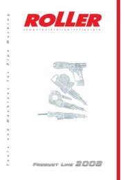
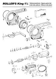
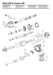
Teileverzeichnis / Spare parts list / Liste des pièces<br />
24<br />
23<br />
28<br />
8<br />
11<br />
26<br />
25<br />
27<br />
<strong>deu</strong> <strong>eng</strong> fra<br />
1 Schnellbefestiger Quick fixing device Attache rapide 059075<br />
2 Gleitstück Sliding piece Pièce coulissante<br />
10–16, 3 /8”– 5 /8” 10–16, 3 /8”– 5 /8” 10–16, 3 /8”– 5 /8” 153126<br />
Gleitstück Sliding piece Pièce coulissante<br />
17–26, 3 /4”– 7 /8” 17–26, 3 /4”– 7 /8” 17–26, 3 /4”– 7 /8” 153127<br />
Gleitstück 32 Sliding piece 32 Pièce coulissante 32 153208R<br />
–– Biegesegment Form Forme<br />
Pos. 3, 5 und 6 Pos. 3, 5 and 6 Pos. 3, 5 et 6<br />
siehe Preisliste see price list voir liste de prix<br />
–– Universal-Gleitstückträger Universal crossbar Contreforme universel<br />
Pos. 1, 2, 4 und 29 Pos. 1, 2, 4 and 29 Pos. 1, 2, 4 et 29<br />
10–26, 3 /8”– 7 /8” 10–26, 3 /8”– 7 /8” 10–26, 3 /8”– 7 /8” 153125R<br />
Gleitstückträger 32 Crossbar 32 Contreforme 32 153115R<br />
5 Klemmfeder Clamping spring Ressort de serrage 153152<br />
6 Kerbschraube Sheet metal screw Vis à tôle 083111<br />
7 Linsenschraube Fillister head screw Vis à tête bombée 083137<br />
8 Sicherungsscheibe Lock washer Rondelle de sécurité 059074<br />
9 Zahnstange Dented rod Crémaillère 153102R<br />
10 Gehäuse Housing Carter 153101A<br />
11 Flügelschraube Wing screw Vis à oreilles 083043<br />
12 Spiralspannstift Spiral pin Goupille spiralée 088090<br />
13 Rastbolzen Catch bolt Boulon d’arrêt 153105R<br />
14 Spiralspannstift Spiral pin Goupille spiralée 088065<br />
15 Druckfeder Pressure spring Ressort de compression 153108<br />
16 Sperrhebel Catch lever Levier d’arrêt 153104<br />
17 Flachfeder Flat spring Ressort plat 153106<br />
18 Zugfeder Traction spring Ressort de traction 153107<br />
19 Vorschubhebel Feed lever Levier d’avance 153103R<br />
20 Zylinderschraube Fillister head screw Vis à tête cylindrique 081057<br />
21 <strong>Hand</strong>griff <strong>Hand</strong>le Poignée 071053<br />
23 Arretierstück Holding piece Pièce d’arrêt 153148<br />
24 Segmenthalter Former holder Support de segment 153147R<br />
25 Halter Support Support 153143R<br />
26 Senkschraube Countersunk screw Vis à tête fraisée 083164<br />
27 Winkel Angle Angle 153142R<br />
28 Senkschraube Countersunk screw Vis à tête fraisée 083167<br />
–– Vorrichtung für Umkehrbögen Device for reverse bends Dispositif pour coudes renversés<br />
Pos. 8, 11, 23–28 Pos. 8, 11, 23–28 Pos. 8, 11, 23–28 153140<br />
29 O-Ring Locking ring Joint torique 060240