Betriebsanleitung Hausanschlußverstärker Operating Instructions ...
Betriebsanleitung Hausanschlußverstärker Operating Instructions ...
Betriebsanleitung Hausanschlußverstärker Operating Instructions ...

Create successful ePaper yourself
Turn your PDF publications into a flip-book with our unique Google optimized e-Paper software.
<strong>Betriebsanleitung</strong><br />
<strong>Hausanschlußverstärker</strong><br />
<strong>Operating</strong> <strong>Instructions</strong><br />
House connecting amplifier<br />
Notice d’utilisation<br />
Amplificateur domestique<br />
GHV 20 E<br />
Best.-Nr./Order code/<br />
N° de commande<br />
940 023-001<br />
GHV 30 E<br />
Best.-Nr./Order code/<br />
N° de commande<br />
940 024-001<br />
eco-power<br />
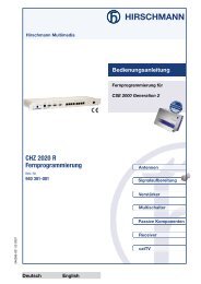
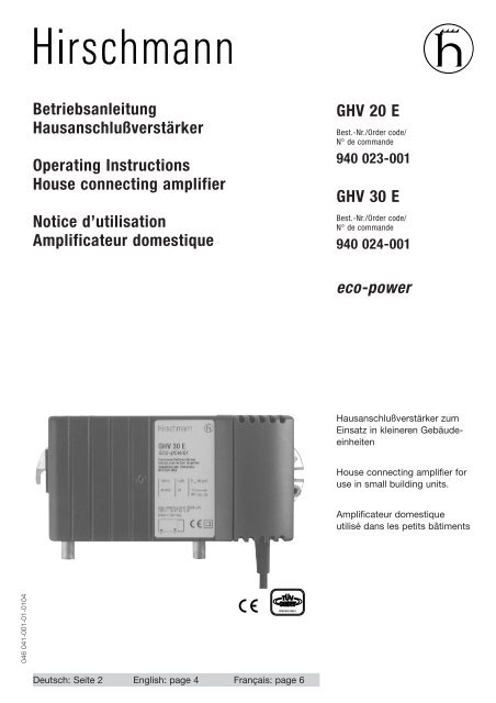
<strong>Hausanschlußverstärker</strong> zum<br />
Einsatz in kleineren Gebäudeeinheiten<br />
House connecting amplifier for<br />
use in small building units.<br />
Amplificateur domestique<br />
utilisé dans les petits bâtiments<br />
046 041-001-01-0104<br />
DIN ISO 9001<br />
Deutsch: Seite 2 English: page 4 Français: page 6
D<br />
Beschreibung<br />
3 Aufbau:<br />
• Verstärkertechnik in kostenoptimaler Ausführung<br />
• Pegelsteller 0...-20 dB am Eingang<br />
• Kompaktes, integriertes Trafo-Netzteil mit<br />
fest verschraubter Kunstoffhaube als Berührungsschutz.<br />
• Maximaler Betriebspegel 105 dBµV<br />
3 Gehäuse:<br />
• Abnehmbarer Deckel mit Zentralschraube<br />
Sicherheitsanforderungen<br />
ACHTUNG:<br />
Die Sicherheitsanforderungen<br />
nach EN 50083-1 sind unbedingt<br />
zu beachten.<br />
3 Potentialausgleich, Erdung, Schutzleiter:<br />
Für die gesamte Anlage ist ein Potentialausgleich<br />
mittels eines mechanisch stabilen<br />
ermöglicht komfortables Konfigurieren<br />
• Das Grundgehäuse aus Druckguß reduziert<br />
die Bauteiletemperaturen und erhöht somit<br />
die Lebensdauer und Zuverlässigkeit.<br />
• HF-Anschlüsse: F-Buchsen<br />
3 Erfüllt die Normen EN 60065<br />
EN 50083-1<br />
EN 50083-2, Klasse A<br />
EN 50083-3, Güteklasse 2<br />
Schutzleiters mit einem Querschnitt von min.<br />
4mm 2 herzustellen. Eine Anschlußmöglichkeit<br />
besteht an der Potentialausgleichsschraube<br />
an der rechten Wandhalterung.<br />
HINWEIS:<br />
Das Gerät darf keinem Tropf- oder<br />
Spritzwasser ausgesetzt werden.<br />
Montage<br />
3 Montageort und Einbaulage so wählen, daß<br />
die Konvektionskühlung des Verstärkers nicht<br />
behindert wird:<br />
- Montage senkrecht (senkrechte Ausrichtung<br />
der Kühlrippen, siehe Abb. 1)<br />
- frei an der Wand<br />
- Einbau in einen Schrank nur bei Beachtung<br />
Recyclinghinweis<br />
Dieses Produkt ist nach seiner<br />
Verwendung entsprechend den aktuellen<br />
Entsorgungsvorschriften Ihres<br />
der zulässigen Betriebs-Umgebungstemperatur<br />
(gemessen am Luftstrom unter<br />
dem Verstärker)<br />
3 Wandbefestigung<br />
- an den Halterungen mit passenden<br />
Schrauben (ø max. 4.8 mm)<br />
- Abstand der Befestigungen 158 mm<br />
Landkreises/Landes/Staates als Elektronikschrott<br />
einer geordneten Entsorgung zuzuführen.<br />
Einstellungen<br />
Der Pegelsteller wird folgendermaßen eingestellt:<br />
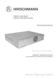
1. Abnehmen des Gehäusedeckels (Abb. 1):<br />
Nach Lösen der Zentralschraube (a) wird der<br />
Deckel anhand der kleinen Halterung links (b)<br />
nach vorne abgenommen.<br />
Nun ist die Leiterplatte zum Einstellen des<br />
Pegelstellers zugänglich.<br />
b<br />
a<br />
Oben<br />
Abb. 1<br />
2
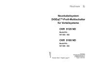
2. Einstellen des Pegelstellers (Abb. 2):<br />
Einstellschraube (c) ganz rechts = 0 dB (Auslieferzustand),<br />
ganz links = -20 dB.<br />
3. Gehäusedeckel schließen:<br />
Den Gehäusedeckel passend auf das Gehäuse<br />
aufsetzen und ringsum andrücken, so daß die<br />
Blechlamellen im geschlossenen Zustand von<br />
innen gegen das Gehäuse gepresst werden.<br />
Zentralschraube einschrauben.<br />
c<br />
Abb. 2<br />
Technische Daten<br />
Typ GHV 20 E GHV 30 E<br />
Bestell-Nr. 940 023-001 940 024-001<br />
Frequenzbereich MHz 40...862<br />
Verstärkung dB 21 29<br />
Frequenzgang dB 1.5 1.5<br />
Dämpfungssteller dB 0...-20 0...-20<br />
Rauschmaß dB 6 6<br />
Rückflußdämpfung dB 16 16<br />
(min. Kat. C) (min. Kat. C)<br />
Impedanz Ω 75 75<br />
Ausgangspegel, IMA = 60 dB<br />
IMA 2 gem. EN 50083-3 dBµV 100 105<br />
IMA 3 gem. EN 50083-3 dBµV 107 109<br />
IMA 3 gem. EN 50083-5 dBµV 113 115<br />
CSO Cenelec 42 Kan. 862 MHz dBµV 97 101<br />
CTB Cenelec 42 Kan. 862 MHz dBµV 100 101<br />
Maximaler Betriebspegel (EMV) dBµV 105 105<br />
Elektrische Anschlußwerte<br />
Versorgungsspannung (50 - 60 Hz) V~ 230 230<br />
Leistungsaufnahme W 3 5<br />
Umgebungsbedingungen gem. EN 60065<br />
Betriebstemperaturbereich °C –25 … +55<br />
Schutzart<br />
II, schutzisoliert<br />
Schutzklasse IP 20<br />
Gehäuse<br />
Gewicht kg ca. 0.65<br />
Abmessungen B x H x T mm 150 x 80 x 50<br />
Schirmdämpfung<br />
gem. EN 0083-2, Klasse A dB 75 min<br />
HF-Anschlüsse<br />
F-Buchsen<br />
Soweit nicht anders vermerkt, sind diese Angaben typische Werte, die in der Praxis im branchenüblichen<br />
Toleranzbereich nach oben oder unten abweichen können.<br />
3
GB<br />
Description<br />
3 Design:<br />
• Cost-effective amplifier design<br />
• Input-side level control to adjust to the<br />
HF input level<br />
• Compact, built-in transformer power supply<br />
unit with fixed plastic cover as touch guard.<br />
• Maximum operating level 105 dBµV<br />
3 Housing:<br />
• Removable lid with central bolt permits<br />
user-friendly configuration<br />
• The die-cast base housing reduces the<br />
component temperatures, enhancing the<br />
unit's durability and reliability.<br />
• RF connections: F connectors<br />
3 Meets EN 60065<br />
EN 50083-1<br />
EN 50083-2, class A<br />
EN 50083-3, quality class 2<br />
Safety Requirements<br />
CAUTION:<br />
Observe the safety requirements<br />
of EN 50083 -1<br />
3 Equipotential bonding<br />
The complete system must be provided with<br />
equipotential bonding by means of a<br />
mechanically stable protective conductor with<br />
Installation<br />
3 Choose a location and orientation that will not<br />
impair the convection cooling of the amplifier:<br />
• Vertical (cooling fins aligned vertically)<br />
• Uncovered on wall<br />
• Installed in a cabinet only in strict<br />
conformance to the permissible ambient<br />
Recycling Information<br />
When this product has reached the end<br />
of its useful life, it is to be turned in for<br />
proper disposal as electronic refuse in<br />
a minimum cross-section of 4mm 2 . There is a<br />
connection point at theat the earthing screw<br />
at the right wall bracket.<br />
NOTE:<br />
The unit must not be exposed to<br />
dripping or splashing water.<br />
operating temperature (measured in the air<br />
stream underneath the amplifier)<br />
3 Wall mounting<br />
• Fixed to brackets by appropriately sized<br />
screws (dia. max. 4.8 mm)<br />
• Fixings 158 mm apart<br />
compliance with the current disposal regulations<br />
of your respective city/country/state.<br />
Setting possibilities<br />
The level control is adjusted as follows:<br />
1. Remove the housing lid (Fig. 1):<br />
After slackening the central bolt (a) lift the lid<br />
off by releasing the catch on the left-hand side<br />
(b).The circuit board for adjustment of the level<br />
control is now accessible.<br />
b<br />
a<br />
above<br />
Fig. 1<br />
4
2. Adjust the level control (Fig. 2):<br />
Adjuster screw (c) full to right = 0 dB (delivery<br />
condition), full to left = -20 dB<br />
3. Close the housing lid:<br />
Put the housing lid on the housing and press<br />
all the way round. The sheet steel segments<br />
will now be pressed against the inner wall of<br />
the housing. Screw in the central screw.<br />
c<br />
Fig. 2<br />
Technical Data<br />
Type GHV 20 E GHV 30 E<br />
Order code 940 023-001 940 024-001<br />
Frequency range MHz 40...862<br />
Gain dB 21 29<br />
Level adjuster dB 0...-20 0...-20<br />
Noise figure dB 6 6<br />
Return loss dB 16 16<br />
(min. categ. C) (min. categ. C)<br />
Impedance Ω 75 75<br />
Output level, IMA = 60 dB<br />
IMA 2 acc. EN 50083-3 dBµV 100 105<br />
IMA 3 acc. EN 50083-3 dBµV 107 109<br />
IMA 3 acc. EN 50083-5 dBµV 113 115<br />
CSO Cenelec 42 ch. 862 MHz dBµV 97 101<br />
CTB Cenelec 42 ch. 862 MHz dBµV 100 101<br />
Maximum operating level (EMV) dBµV 105 105<br />
Connected loads<br />
Supply voltage (50 - 60 Hz) VAC 230 230<br />
Power consumption W 3 5<br />
Ambient conditions to EN 60065<br />
<strong>Operating</strong> temperature range °C –25 … +55<br />
Degree of protection<br />
II, totally insulated<br />
Protection class IP 20<br />
Housing<br />
Weight kg ca. 0.65<br />
Dimensions W x H x D mm 150 x 80 x 50<br />
Screening attenuation<br />
acc. EN 0083-2, class A dB 75 min<br />
RF connections<br />
F connectors<br />
Unless otherwise stated, these specifications are typical values which in practice may be higher or lower inside the<br />
tolerance range usual for the branch.<br />
5
F<br />
Description<br />
3 Configuration:<br />
• Technique d’amplification en exécution<br />
économique optimale<br />
• Réglage du niveau à l’entrée pour<br />
adaptation à chaque niveau d’entrée HF<br />
• Alimentation secteur compacte avec<br />
transformateur et capot de protection<br />
plastique solidement vissé.<br />
• Niveau de fonctionnement max. 105 dBµV<br />
3 Boîtier :<br />
• Le couvercle amovible avec vis centrale<br />
facilite la configuration.<br />
Règles de sécurité<br />
ATTENTION:<br />
Il faut impérativement respecter<br />
les règles de sécurité<br />
conformément à EN 50083-1.<br />
3 Liaison équipotentielle :<br />
Etablir pour l'ensemble de l'installation une<br />
liaison équipotentielle à l'aide d'un conducteur<br />
Montage<br />
3 L’emplacement de montage et la position de<br />
l’appareil ne doivent pas empêcher le<br />
refroidissement par convection de<br />
l’amplificateur.<br />
• Montage en position verticale (orientation<br />
verticale des ailettes de refroidissement)<br />
• Librement au mur<br />
• Le montage dans une armoire est possible à<br />
<strong>Instructions</strong> pour le recyclage<br />
Après son utilisation, ce produit doit être<br />
éliminé en conformité avec la<br />
• La base du boîtier en métal moulé sous<br />
pression réduit la température des<br />
composants et augmente ainsi la durée de<br />
vie et la fiabilité.<br />
• Prises HF Douilles F<br />
3 Conforme aux normes<br />
EN 60065<br />
EN 50083-1<br />
EN 50083-2, classe A<br />
EN 50083-3, classe de qualité 2<br />
de protection stable mécaniquement et d'une<br />
section min. de 4 mm 2 . Il peut être raccordé<br />
sur le filetage du support mural à droit.<br />
REMARQUE:<br />
L’appareil ne doit pas être<br />
exposé aux gouttes ou aux<br />
projections d’eau.<br />
condition de respecter la température<br />
ambiante et la température de<br />
fonctionnement admissibles (mesurées dans<br />
le courant d’air sous l’amplificateur)<br />
3 Fixation murale<br />
• Par la fixation prévue avec les vis<br />
appropriées (ø max. 4,8 mm)<br />
• distance 158 mm<br />
réglementation en vigueur dans votre<br />
pays/province/état comme déchet électronique.<br />
Réglages<br />
Le réglage du niveau s’effectue comme suit<br />
1. Retirez le couvercle:<br />
Après desserrage de la vis centrale (a) retirez le<br />
couvercle vers le haut à l’aide de la petite<br />
fixation latérale gauche (b).<br />
Le circuit imprimé est maintenant accessible<br />
pour le réglage du niveau.<br />
b<br />
a<br />
en haut<br />
Fig. 1<br />
6
2. Réglage du niveau (Fig. 2) :<br />
Vis de réglage en butée (c) vers la droite =<br />
0 dB (état de livraison), en butée vers la<br />
gauche = -20 dB<br />
3. Fermez la couvercle du boîtier:<br />
Pour refermer le boîtier, positionnez le couvercle<br />
sur le boîtier et appliquez une pression sur la<br />
périphérie de façon que les lames de fer blanc<br />
appuient sur les murs du boîtier à l’intérieur.<br />
Revissez la vis centrale.<br />
c<br />
Fig. 2<br />
Caractéristiques techniques<br />
Type GHV 20 E GHV 30 E<br />
N° de commande 940 023-001 940 024-001<br />
Plage de fréquence MHz 40...862<br />
Amplification dB 21 29<br />
Réglage atténuation dB 0...-20 0...-20<br />
Facteur de bruit dB 6 6<br />
Affaiblissement dB 16 16<br />
courants réfléchis (min. cat. C) (min. cat. C)<br />
Impédance Ω 75 75<br />
Niveau de sortie, IMA = 60 dB<br />
IMA 2 selon EN 50083-3 dBµV 100 105<br />
IMA 3 selon EN 50083-3 dBµV 107 109<br />
IMA 3 selon EN 50083-5 dBµV 113 115<br />
CSO Cenelec 42 can. 862 MHz dBµV 97 101<br />
CTB Cenelec 42 can. 862 MHz dBµV 100 101<br />
Niveau maximal de service (EMV) dBµV 105 105<br />
Raccordement secteur<br />
Tension d’alimentation (50 - 60 Hz) VAC 230 230<br />
Puissance absorbée W 3 5<br />
Conditions d’environnement selon EN 60065<br />
Plage de température de service °C –25 … +55<br />
Mode de protection<br />
II, totally insulated<br />
Classe de protection IP 20<br />
Boîtier<br />
Poids kg environ 0.65<br />
Dimensions W x H x D mm 150 x 80 x 50<br />
Effet de blindage<br />
selon EN 0083-2, classe A dB 75 min<br />
Prises HF<br />
Douilles F<br />
Sans autre remarque particulière, ces données sont des valeurs typiques, qui peuvent dans la pratique, varier en plus<br />
ou en moins, dans une plage de tolérance couramment admises dans la profession.<br />
7
<strong>Betriebsanleitung</strong> GHV 20/30 E • <strong>Operating</strong> instructions GHV 20/30 E • Notice d’utilisation GHV 20/30 E<br />
Hirschmann Multimedia Electronics GmbH<br />
Stuttgarter Str. 45 - 51<br />
D-72654 Neckartenzlingen<br />
Phone +49 (0) 180 32 32-341<br />
www.hirschmann.com