066G103 GROB G-103.indd - Absolu-Modélisme
066G103 GROB G-103.indd - Absolu-Modélisme
066G103 GROB G-103.indd - Absolu-Modélisme

You also want an ePaper? Increase the reach of your titles
YUMPU automatically turns print PDFs into web optimized ePapers that Google loves.
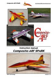
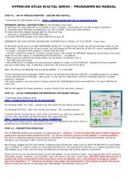
Order N° <strong>066G103</strong><br />
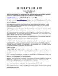
Planeur semi-maquette<br />
Semi-scale sailplane<br />
Caractéristiques techniques/Technical data:<br />
Echelle/scale: 1:6,5<br />
Envergure/wingspan: 2,77m<br />
Longueur/length: 1,25m<br />
Poids/TO weight: 2,4/2,5kg<br />
Surface/wing area: 41,4dm 2<br />
Profil/airfoil:<br />
MH32 mod.<br />
Equipements recommandés/Recommended equipments:<br />
Moteur/motor: XPower XC3223/10LS<br />
Contrôleur/ESC: XPower XREG60<br />
Accu/battery pack: XPower Xtreme11,1V 2600mAh (3S)<br />
Hélice/prop:<br />
XPower FOLDING PROP 13x6” #099FB1306<br />
Porte pales/prop hub: XPower 20mm +5° #099H200805<br />
Radio/RC set:<br />
Récepteur/receiver: XPower RP8D1<br />
Ailerons:<br />
2 servos TOPMODEL SS1816<br />
Profondeur/Elevator: 1 servo TOPMODEL SS1816<br />
Direction/Rudder: 1 servo TOPMODEL MS2414<br />
AF/AB:<br />
AF ELECTRIQUE/ELECTRIC SPOILER 250mm #099ELAF25<br />
ATTENTION !<br />
Ce modèle à construire n’est pas un jouet, il<br />
ne convient pas aux enfants de moins de 14 ans.<br />
Une mauvaise utilisation de ce matériel peut<br />
provoquer des dommages matériels ou corporels.<br />
Vous êtes pleinement responsable<br />
lorsque vous utilisez votre modèle.<br />
Volez à une distance de sécurité des zones<br />
habitées.<br />
Soyez sûr que personne n’émet sur la même<br />
fréquence que vous.<br />
CAUTION !<br />
This model construction kit is not a toy and is not<br />
suitable for children under the age of 14.<br />
Incorrect use of this material could cause material<br />
damage ou personal injury.<br />
You are fully responsible for your actions when you<br />
use this model.<br />
Fly at a safe distance from occupied zones.<br />
Be sure that no one else is using the same<br />
frequency as you.<br />
Distribué par / Distributed by:<br />
TOPMODEL S.A.S.<br />
Le jardin d’entreprises de SOLOGNE - F-41300 SELLES SAINT DENIS - www.topmodel.fr<br />
©TOPMODEL 2010
MERCI d’avoir choisi le planeur semi-maquette <strong>GROB</strong> G103C TWIN III ACRO ECOTOP!<br />
Nous avons fait un grand effort en dessinant et construisant ce planeur pour qu’il soit le meilleur modèle que vous ayez jamais construit et fait voler.<br />
Nous vous fournissons un kit avec la plus haute qualité et les meilleures performances possibles.<br />
Nous vous souhaitons un grand succès en assemblant et en faisant évoluer votre nouveau <strong>GROB</strong> G103C TWIN III ACRO ECOTOP.<br />
IMPORTANT: Merci de bien vouloir lire et étudier cette notice de montage avant de commencer l’assemblage. Faire l’inventaire des pièces à l’aide de la nomenclature<br />
pour contrôler qu’il n’y a pas de manquant ou d’imperfection.<br />
Merci de contacter immédiatement TOPMODEL si vous constatez une pièce manquante ou une pièce endommagée.<br />
GARANTIE: Il est important de notifier à TOPMODEL tous dommages ou problèmes avec ce modèle dans les 7 jours suivant la réception du kit pour bénéficier de la<br />
garantie. En cas de retour du modèle, le client est responsable du transport et le port retour est à sa charge. En cas de défaut, la pièce sera échangée ou remplacée une<br />
fois que celle-ci sera réceptionnée par TOPMODEL pour expertise (transport à la charge du propriétaire). En cas de problème, n’hésitez pas à contacter TOPMODEL.<br />
TOPMODEL ne peut pas contrôler la dextérité du modéliste et ne peut pas influencer le constructeur durant l’assemblage ou l’utilisation de ce modèle radio-commandé.<br />
Aussi, nous ne pouvons, en aucun cas, être tenus responsables des dégâts matériels, accidents corporels ou décès pouvant être causés par ce modèle réduit.<br />
L’acheteur/utilisateur accepte toutes les responsabilités en cas de problèmes structurels ou mécaniques.<br />
POUR ASSEMBLER CE KIT<br />
Pour assembler ce kit, vous aurez besoin des produits énumérés ci-dessous:<br />
■ COLLES: Cyano fluide et épaisse, époxy 30mn et 5mn, colle silicone.<br />
■ OUTILS: Couteau de modéliste, tournevis cruciforme (petit et moyen), pince à bec fin, pince coupante, ciseaux, ruban adhésif, ruban adhésif de<br />
masquage, ruban adhésif double-faces, perçeuse (foret Ø0,6-1,8-3 et 3,5mm), papier verre, règle, feutre, clips, alcool, fer à souder, chiffon.<br />
■ MOTEUR<br />
-Moteur brushless XPower XC3223/10LS<br />
-Porte -pales<br />
-Pales d’hélice repliables<br />
-AF électriques 250mm<br />
■ RADIO<br />
-Ensemble radio (9 voies mini avec 4<br />
servos et un contrôleur)<br />
-Micro servo x3, mini servo x1<br />
-Rallonge servo (700mm x2, 800mm x1)<br />
-Contrôleur<br />
-Accu de propulsion LiPo<br />
RETENDRE L’ENTOILAGE<br />
1) Déballez doucement en prenant soin de ne pas endommager une<br />
partie du kit. Déballez toutes les pièces de leur emballage plastique pour<br />
inspection.<br />
Avant de commencer tout montage ou de poser tout auto-collant, il<br />
est très important de retendre l’entoilage déjà appliqué. A cause du<br />
transport, de la chaleur et de l’humidité qui varient beaucoup suivant les<br />
différents climats, l’entoilage peut se détendre et se “rider” au soleil. Si<br />
vous prenez le temps de retendre l’entoilage, vous serez récompensé par<br />
un modèle qui restera magnifique dans le temps.<br />
3) Si les bulles persistent, piquer les bulles à l’aide d’une aiguille pour<br />
évacuer l’air emprisonné et chauffer de nouveau.<br />
4) Utilisez le décapeur thermique avec beaucoup de précaution. Faire<br />
attention de ne pas chauffer au même endroit trop longtemps. Cela<br />
pourrait trop rétracter les bords et laisser un espace découvrant le bois<br />
aux jointures des différentes couleurs. Les filets sont particulièrement<br />
vulnérables à la surchauffe.<br />
2) En utilisant un fer à soler et un chiffon doux, “repassez” délicatement<br />
et “suivez” en appliquant le film avec le chiffon. Si des bulles apparaissent,<br />
votre fer est peut être trop chaud. Réduire la température et travaillez<br />
doucement et patiemment.<br />
5) Votre modèle est entoilé avec de l’Oracover® blanc N°10.<br />
2
THANK YOU for your purchase of the ECOTOP semi-scale sailplane <strong>GROB</strong> G103C TWIN III ACRO ARF!<br />
We made a main effort while drawing and building this sailplane so that it is the best model one than you ever built and fly.<br />
We provide you a kit with the highest quality and the best possible performances.<br />
We wish you a great success while assembling and flying your new ECOTOP <strong>GROB</strong> G103C TWIN III ACRO.<br />
IMPORTANT: Please take a few moments to read this instruction manual before beginning assembly. Do an inventory of the parts using the parts list, to control that<br />
there is no lack or imperfection. Thank you to contact TOPMODEL immediately, if you note a missing part or a damaged part.<br />
WARRANTY: It is important to notify to TOPMODEL all damage or problems with this model within 7 days following the reception of the kit to be able to benefit the<br />
warranty. In the event of return of the model, the customer is responsible for transport and return shipping cost is at his expenses. In the event of defect, the part will be<br />
exchanged or replaced once this one will be delivered to TOPMODEL for expertise (transport on your cost). In the event of problem, do not hesitate to contact TOPMODEL.<br />
TOPMODEL cannot control the dexterity of the modeler and cannot influence the builder during the assembly or the use of this radiocontrolled model, thus TOPMODEL will in<br />
no way accept or assume responsability or liability for damages resulting from the use of this user assembled product.<br />
The purchaser/user accepts all the responsibilities in the event of structural or mechanical problems.<br />
TO ASSEMBLE THIS KIT<br />
To assemble this kit, you’ll need the items listed below:<br />
■ ADHESIVE: Cyanoacrylate thin and thick, epoxy 30 and 5min, silicon adhesive.<br />
■ TOOLS: Knife (X-acto), Phillips screw driver (small and medium), needle tip pliers, pliers, scissors, scotch tape, masking tape, double sticking<br />
tape, drill (with 0,6-1,8-3 and 3,5mm bits), sanding paper, ruler, ball point pen, clips, alcohol, soldering iron, piece of cloth or rags.<br />
■ MOTOR<br />
-XPower brushless motor XC3223/10LS<br />
-Propeller hub<br />
-Folding propeller<br />
-Electric spoilers 250mm<br />
■ RADIO<br />
-Radio set (more than 9 channels<br />
with servos and ESC)<br />
-Micro servo x3, mini servo x1<br />
-Servo extension (700mm x2, 800mm x1)<br />
-Electric Speed Controller<br />
-LiPo battery<br />
RE-SHRINKING THE COVERING<br />
1) Open you kit slowly and take care not to damage any parts of the kit.<br />
Remove all parts from their plastic protective bags for inspection. Before<br />
doing any assembly or installation of any decals, it is very important to<br />
re-shrink or re-tighten the already applied covering. Due to the shipping<br />
process, heat and humidity changes from different climates, the covering<br />
may become lose and wrinkle in the sun. If you take the time to re-tighten<br />
the covering, you’ll be rewarded with a long lasting beautifully covered<br />
model.<br />
3) If bubbles persist, use a small pin to punch holes in the bubble to<br />
relieve trapped air and reheat.<br />
4) Use your heat gun with extreme caution. Take care not to apply too<br />
much heat to one area for long periods of time. This may cause the trim<br />
colors to over shrink and pull away leaving sightly gaps on the color lines.<br />
The trim stripes are especially vulnerable to over shrinking.<br />
2) Using your covering iron with a soft sock, gently apply pressure and rub<br />
in the covering. If any bubbles occur, your iron may be too hot.<br />
Reduce heat and work slowly.<br />
5) Your model is covered with Oracover® white #10<br />
3
3<br />
7<br />
2-41<br />
4-8<br />
3-4<br />
2-4<br />
4<br />
2-8<br />
4C<br />
4-5<br />
3-5<br />
2-5<br />
24T<br />
3-8<br />
2-23<br />
2-2<br />
7<br />
1-1<br />
10<br />
4-5 24<br />
1<br />
2<br />
2<br />
6<br />
8-1<br />
8-1<br />
2AF<br />
AT<br />
551<br />
551<br />
6-2<br />
6C<br />
551<br />
4-5<br />
2AF<br />
6S
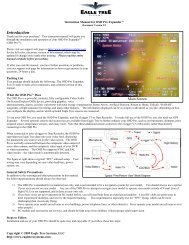
CONTENU DU KIT<br />
KIT CONTENT<br />
N° pièce Désignation Matériau, dimensions (mm) Qté<br />
0 notice de montage manuel A4 01<br />
1 fuselage fibre de verre 01<br />
1-1 couple moteur CTP 3mm + vis M3x10mm + écrou prisonnier M3 02+04+04<br />
1-2 platine radio CTP 3mm 01<br />
2 aile polystyrène coffré-entoilé 02<br />
2-2 fixation aile tige filetée M4 + écrou papillon + rondelle CTP 3mm 02+02+02<br />
2-4 set fixation servos ailerons renfort balsa 1,5mm + set platine servo CTP 2mm<br />
+ vis à bois 2,3x6mm<br />
02+02<br />
+04<br />
2-41A carénage servo aileron plastique moulé 01 set<br />
2-5 tringlerie aileron CAP filetée un bout M2 L=100mm + chape + écrou 02+02+02<br />
2-8 guignol aileron aluminium 02<br />
2-23 saumon fibre verre 02<br />
24 clé d’aile jonc acier 01<br />
24T téton d’aile CAP Ø4 L=30mm 02<br />
2AF chapeau d’AF plastique 02<br />
3 empennage horizontal polystyrène coffré-entoilé 01<br />
3-4 vis fixation stab. vis M3x25mm 02<br />
3-5 tringlerie de profondeur CAP filetée un bout M2 L=100mm + chape + écrou 01+01+01<br />
3-8 guignol de profondeur laiton 01<br />
4 volet de direction balsa entoilé 01<br />
4-5 tringlerie direction CAP filetée un bout M2 L=100mm + chape + écrou<br />
+ CAP L=250mm + tourillon bois dur Ø8 L=600m<br />
4-8 guignol de direction aluminium 01<br />
4C charnière plastique type bâton 03<br />
6 set cabine plastique moulé + fibre de verre 01<br />
6-2 set fixation cabine tourillon métal + support CTP 2mm+ verrou<br />
+ support CTP 2mm+ vis à bois 2x6mm<br />
01+01+01<br />
+01+01<br />
01+01+01<br />
+01+01<br />
6C aménagement cockpit plastique moulé 01<br />
6S siège avant plastique moulé 01<br />
7 décoration planche autocollante 01<br />
8-1 roue Ø60mm + Ø40mm 01+01<br />
10 train d’atterrissage set couples train principal + rondelle CTP + axe métal 01+04+01<br />
+ set couples roue avant + rondelle CTP + axe métal +01+02+01<br />
551 tableau de bord set tableau de bord “champignon”<br />
+ planche de bord plastique<br />
AT appui-tête mousse 02<br />
01<br />
+02<br />
Part # Item Material, dimensions (mm) Qty<br />
0 building instructions A4 booklet 01<br />
1 fuselage pod fiberglass 01<br />
1-1 motor mount plywood 3mm + screw M3x10 + blind nut M3 02+04+04<br />
1-2 servo tray plywood 3mm 01<br />
2 wing balsa sheeted foam core- covered 02<br />
2-2 wing fixing threaded rod M4 + ear nut + plywod 3mm washer 02+02+02<br />
2-4 ailerons servos fixing set servo mount reinforcement balsa 1,5mm + servo<br />
mount plywood 2mm + self tapping screw 2,3x6mm<br />
02+02<br />
+04<br />
2-41A aileron servo cover molded plastic 01 set<br />
2-5 aileron and flap linkage music wire threaded one end M2 L=100mm + clevis + nut 02+02+02<br />
2-8 aileron control horn aluminium 02<br />
2-23 tip fiberglass 02<br />
24 wing joiner steel rod 01<br />
24T incidence pin music wire Ø4 L=30mm 02<br />
2AF spoiler cover plastic 02<br />
3 horizontal tail balsa sheeted foam core- covered 01<br />
3-4 horizontal tail fixing screw M3x25mm 02<br />
3-5 elevator linkage music wire threaded one end M2 L=100mm + clevis + nut 01+01+01<br />
3-8 elevator horn brass 01<br />
4 rudder balsa covered 01<br />
4-5 rudder linkage music wire threaded one end M2 L=100mm + clevis + nut<br />
+music wire L=250mm + Ø8 dowel pushrod L=600mm<br />
4-8 rudder horn aluminium 01<br />
4C hinge plastic pin type 03<br />
6 cabin set vacumed plastic + fiberglass 01<br />
6-2 cabin fixing set metal dowel +plywood 2mm mount + latch<br />
+ plywood 2mm mount + self tapping screw 2x6mm<br />
01+01+01<br />
+01+01<br />
01+01+01<br />
+01+01<br />
6C cockpit vacumed plastic 01<br />
6S front seat vacumed plastic 01<br />
7 art work sticker sheet 01<br />
8-1 wheel Ø60mm + Ø40mm 01+01<br />
10 landing gear main gear formers set + plywood washer + axle<br />
+ nose gear formers set + plywood washer + axle<br />
551 instrument panel “mushrom” instrument console set<br />
+instrument board<br />
AT head rest foam 02<br />
01+04+01<br />
+01+02+01<br />
01<br />
+02<br />
5
INSTALLATION TRINGLERIE AILERONS/ AILERONS LINKAGE INSTALLATION<br />
Rassembler les pièces ci-contre pour réaliser la tringlerie des ailerons.<br />
2-4<br />
2-4<br />
Gathered parts for aileron linkage<br />
2-41A<br />
2-4<br />
2-4<br />
2-4<br />
2-8<br />
2-5<br />
1) Découper soigneusement l’entoilage au niveau du puit de servo<br />
d’aileron.<br />
Carefully cut out the film covering the servo room<br />
in the wing.<br />
2-4<br />
2) Coller au fond du puit, le renfort 2-4 en balsa 1,5mm à l’époxy 5mn.<br />
Secure servo room reinforcement 2-4 to the bottom<br />
of servo room with 5’ epoxy.<br />
2) Utiliser une rallonge de 700mm pour le servo et sécuriser la connection<br />
avec du ruban adhésif ou de la gaine thermo. Passer le le câble<br />
dans l’aile à l’aide la cordelette dèjà passée dans l’aile.<br />
Use a 700mm extension cord for the servo and secure<br />
the connection with tape or heat shrink tube.<br />
Thread the cord through the wing with string<br />
already routed into the wing.<br />
2-4<br />
2) Construire le support servo 2-4 comme sur la photo, coller les<br />
pièces entre-elles à la cyano. Monter le servo sur le support terminé<br />
avec les 2 vis à bois 2-4 de 2,3x6mm.<br />
2-4<br />
2-4<br />
Construct servo mount 2-4 as photo, secure parts<br />
together with cyano glue. Secure servo completed<br />
mount with 2.3x6mm self tapping screws 2-4.<br />
6
INSTALLATION TRINGLERIE AILERONS/ AILERONS LINKAGE INSTALLATION<br />
5) Immobiliser le volet d’aileron au neutre avec du ruban adhésif. Décaler<br />
le palonnier du servo pour obtenir 90° de course. Couper la partie<br />
non nécessaire du palonnier du servo.<br />
2-5<br />
2-8<br />
Maintain the aileron to neutral position with<br />
paper tape. Off-set the servo arm one notch to give<br />
90° stroke. The unnecessary part of the servo<br />
arm part is cut out<br />
6) Positionner le guignol 2-8 sur l’aileron et faire un trou de 4mm dans<br />
l’aileron (sans déboucher à l’extrados!).<br />
5mm<br />
Locate the control horn 2-8 on the ailerons and<br />
make 4mm hole in the aileron.<br />
2-5<br />
2-5<br />
2-5<br />
2-8<br />
7) Coller le guignol à l’époxy 5mn dans l’aileron.<br />
Glue the control horn 2-8 on the aileron with 5’<br />
epoxy glue.<br />
8) Après installation du guignol, visser l’écrou M2 sur la tringlerie 2-5<br />
puis visser la chape. Aileron et servo au neutre, repérer la longueur de<br />
la tringlerie.<br />
After the control horn is installed, put the 2mm<br />
nut on the pushrod and attach the clevis to pushrod.<br />
Whith the aileron and servo in neutral position,<br />
mark the pushrod for control horn attachment.<br />
9) Faire une baïonnette sur le repère que vous venez de tracer.<br />
Installer la tringlerie comme sur la photo.<br />
Make a Z type bend on the mark. Install the aileron<br />
linkage as photo.<br />
10) Repérer la position du support servo dans l’aile.<br />
2-4<br />
Temporarily attach the aileron servo mount to the<br />
main wing.<br />
11) Le servo est démonté puis le support servo 2-4 est collé solidement<br />
à l’époxy 5mn dans l’aile.<br />
The servo is removed, and the servo mount 2-4 is<br />
bonded to the main wing firmly with 5’ epoxy glue.<br />
12) Découper avec un cutter ou avec une paire de ciseaux, le carénage<br />
de servo d’aileron 2-41A en suivant les lignes. Fixer le carénage sur le<br />
dessous de l’aile avec du scotch double-faces (non inclus).<br />
2-41A<br />
Cut the plastic aileron servo cover 2-41A with a<br />
knife or scissors according to the lines. Attach<br />
the aileron servo cover on the wing bottom with<br />
double sided tape (not included).<br />
7
INSTALLATION AEROFREINS/ AIRBRAKES INSTALLATION<br />
Rassembler les pièces ci-contre pour réaliser l’installation des<br />
aérofreins électriques 250mm XPower.<br />
#ELAF25 non fournis/not included<br />
Gathered parts for XPower 250mm electric airbrakes<br />
installation.<br />
2AF<br />
2AF<br />
1) Découper minutieusement le film d’entoilage qui recouvre la<br />
réservation pour l’installation de l’aérofrein en laissant un retour de 3 à<br />
5mm que vous collerez dans le puit d’AF avec le fer à entoiler.<br />
Carefully cut out the film covering the airbrake<br />
installation room, leaving 3 to 5mm fringe in<br />
spoiler room and fix in place with iron.<br />
2<br />
2) Attacher le cable de l’aérofrein à la cordelette puis le passer dans<br />
l’aile 2. L’aérofrein est installé dans son puit une fois que le câble est<br />
passé dans l’aile.<br />
Tie the lead wire of the electric airbrake with<br />
string and pass it through main wing 2. The airbrake<br />
is installed in the main wing while passing<br />
the lead wire in the main wing.<br />
3) L’aérofrein correctement installé doit être comme sur la photo.<br />
Installed properly airbrake should like photo.<br />
8
INSTALLATION AEROFREINS/ AIRBRAKES INSTALLATION<br />
4) Connecter l’aérofrein au SERVO TESTER pour contrôler le bon<br />
fonctionnement.<br />
Connect the airbrake to SERVO TESTER and battery<br />
to check movement.<br />
5) Sortir l’aérofrein et le fixer en place avec des vis à bois 2x5mm (non<br />
fournies) vissées dans les trous existants dans le fond du boîtier de<br />
l’AF.<br />
Extend the airbrake and fix in place with 2x5mm<br />
self tapping screws (not included) installed in the<br />
pre-existing holes at the botton of the airbrake<br />
case.<br />
6) Après fixation de l’AF, ajuster la taille du chapeau d’aérofrein 2AF<br />
pour qu’il s’adapte parfaitement au-dessus de la réservation de l’AF.<br />
2AF<br />
After airbrake is installed, adjust the size of the<br />
airbrake cover 2AF to fit perfectly over the airbrake<br />
room.<br />
7) Le chapeau d’aérofrein 2AF est collé sur l’AF avec du scotch doublefaces<br />
(pas inclus dans le kit).<br />
The airbrake cover 2AF is secured on the airbrake<br />
with a double-faced tape (not include in the kit).<br />
9
INSTALLATION TRAIN PRINCIPAL/ MAIN GEAR INSTALLATION<br />
8-1<br />
Rassembler les pièces ci-contre pour réaliser l’installation du train<br />
principal.<br />
10<br />
Gathered parts for main gear installation.<br />
10<br />
10<br />
10<br />
10<br />
10<br />
1) Sélectionner l’insert 10 adapté pour l’axe de roue et l’introduire<br />
dans le moyeu de roue. Le poncer si nécessaire pour un ajustage<br />
parfait.<br />
Select a suitable spacer 10 for the axle size and<br />
insert it in the wheel as shown. Sand spacer if<br />
necessary for a perfect fit.<br />
8-1<br />
2) La rondelle entretoise en CTP 3mm est collée sur le couple du train<br />
principal 10 comme montré.<br />
The spacer of 3mm plywood is bonded to the main<br />
gear mount 10 as shown.<br />
10<br />
3) L’ensemble supportant la roue principale est assemblé comme sur la<br />
photo (utiliser de la colle époxy 30mn).<br />
The main gear mount is assembled as shown in<br />
the photo (use 30’ epoxy glue).<br />
10
INSTALLATION TRAIN PRINCIPAL/ MAIN GEAR INSTALLATION<br />
4) Le pneu est installé en passant l’axe à travers les trous des couples.<br />
Contrôler que la roue tourne librement, élargir le trou de l’insert<br />
plastique si besoin.<br />
The tire is installed by passing the axle through<br />
the holes in mount. Check the movement of wheel,<br />
wheter it turns freely, widen plastic spacer axle if<br />
needed.<br />
Fixer l’axe à l’époxy<br />
Fix axle with epoxy<br />
6) Essayer à blanc le train principal dans le fuselage et contrôler que la<br />
roue tourne librement.<br />
Trial fit the main gear in the fuselage and check<br />
the movement of wheel.<br />
7) La roue doit sortir du fuselage comme montré sur la photo. Poncer<br />
et ajuster les pièces en CTP si nécessaire<br />
The wheel should extend out of the fuselage as<br />
shown in the photo. Sand and adjust the plywood<br />
mount if necessary.<br />
7) Le train principal est fixé dans la cellule avec de la colle époxy. Il est<br />
bien de renforcer ce collage. Merci d’utiliser du tissu fibre de verre, etc.<br />
(non inclus dans le kit).<br />
The main gear mount is secured to the body with<br />
epoxy adhesive. It is best to reinforce mount in<br />
body. Please, use fiberglass cloth, etc.<br />
(not included in the kit).<br />
Tissu fibre de verre<br />
Fiberglass cloth<br />
11
INSTALLATION TRAIN AVANT/ NOSE GEAR INSTALLATION<br />
8-1<br />
10<br />
Rassembler les pièces ci-contre pour réaliser l’installation du train<br />
principal.<br />
Gathered parts for main gear installation.<br />
10<br />
10<br />
10<br />
10<br />
10<br />
1) Sélectionner l’insert 10 adapté pour l’axe de roue et l’introduire<br />
dans le moyeu de roue. Le poncer si nécessaire pour un ajustage<br />
parfait.<br />
Select a suitable spacer 10 for the axle size and<br />
insert it in the wheel as shown. Sand spacer if<br />
necessary for a perfect fit.<br />
2) L’ensemble supportant la roue avant est assemblé comme sur la<br />
photo (utiliser de la colle époxy 30mn).<br />
The nose gear mount is assembled as shown in the<br />
photo (use 30’ epoxy glue).<br />
Coller à l’époxy<br />
Fix with epoxy<br />
3) Faire un large congé d’époxy au niveau de la rondelle entretoise CTP<br />
comme sur la photo.<br />
Use a generous amount of epoxy on the plywood<br />
spacer of mount as shown.<br />
Coller l’axe à l’époxy<br />
Fix axle with epoxy<br />
12<br />
4) Le pneu est installé en passant l’axe à travers les trous des couples.<br />
Contrôler que la roue tourne librement, élargir le trou de l’insert<br />
plastique si besoin.<br />
The tire is installed in mount with the axle. At this<br />
time, check whether wheel turns freely.<br />
5) Fixer l’axe en place avec un généreux congé de colle époxy appliqué<br />
sur le couple comme montré.<br />
Fix axle in place wit a generous amount of epoxy<br />
applied to plywood mount and axle as shown.
INSTALLATION TRAIN AVANT/ NOSE GEAR INSTALLATION<br />
6) Les cales CTP 3mm (forme en U) sont collées sur le bâti comme<br />
montré. Poncer les extrémités en diagonale en fonction de la forme du<br />
fuselage.<br />
The spacer of 3mm plywood (U-shaped) is bonded<br />
to the mount as shown. Sand edges down diagonally<br />
according to in the body.<br />
Fixer l’axe à l’époxy<br />
Fix axle with epoxy<br />
7) Essayer à blanc le train avant dans le fuselage et contrôler que la<br />
roue tourne librement.<br />
Trial fit the wheel in the body as shown and check<br />
the movement of the wheel.<br />
8) La roue doit sortir du fuselage comme montré sur la photo. Poncer<br />
et ajuster les pièces en CTP si nécessaire<br />
The wheel should extend out of the fuselage as<br />
shown in the photo. Sand and adjust the plywood<br />
mount if necessary.<br />
9) Le train avant est fixé dans la cellule avec de la colle époxy. Il est<br />
recommandé de renforcer ce collage. Merci d’utiliser du tissu fibre de<br />
verre, etc. (non inclus dans le kit).<br />
The main gear mount is secured to the body with<br />
epoxy adhesive. It is best to reinforce mount in<br />
body. Please, use fiberglass cloth, etc.<br />
(not included in the kit).<br />
Tissu fibre de verre<br />
Fiberglass cloth<br />
13
INSTALLATION MOTEUR/ MOTOR INSTALLATION<br />
#099FB1306<br />
#099H200805<br />
#099C322310LS<br />
Rassembler les pièces ci-contre pour réaliser l’installation du moteur et<br />
de l’hélice repliable.<br />
Le moteur brushless XPower XC3223/10LS, le porte-pale XPower<br />
20mm +5° et les pales d’hélice repliable XPower 13x6 ne sont pas<br />
inclus dans le kit.<br />
1-1 1-1 1-1<br />
Gathered parts for motor and folding propeller<br />
installation.<br />
XPower XC3223/10LS brushless motor, XPower<br />
20mm +5° hub, 13x6 prop blades are not included<br />
in the kit.<br />
1) Coller les deux couples moteur 1-1 ensembles. Fixer solidement les<br />
écrous prisonniers dans le plus petit couple comme montré.<br />
Bond the two motor mount 1-1 pieces together.<br />
Firmly install the blind nuts in the smaller wood<br />
piece as shown.<br />
2) Le moteur est vissé sur le couple moteur avec les vis M3x10mm.<br />
-La flèche gravée montre le bas du fuselage.<br />
The motor is installed in the mount with 3x10mm<br />
machine screws 1-1.<br />
-The engraved arrow of the mount is positionned<br />
under the body<br />
3) Appliquer un ruban adhésif papier sur le fuselage et tracer une<br />
droite reliant le nez à la partie la plus haute du karman d’aile. Cette<br />
droite matérialise la ligne de référence pour l’installation du moteur.<br />
Merci d’installer le moteur parallèle à cette droite.<br />
Apply masking tape to the side of the fuselage and<br />
draw a line from the nose to the upper surface of<br />
the wing. This line is the reference line of the motor<br />
installation.<br />
Please, install the motor parallel to the line.<br />
14
INSTALLATION MOTEUR/ MOTOR INSTALLATION<br />
4) Quand la position est déterminée, pointer le couple moteur à la<br />
cyano.<br />
When the position is determined, fix mount in<br />
nose with cyanoacrylate.<br />
Coller à l’époxy<br />
Fix with epoxy<br />
5) Renforcer le collage du couple avec un généreux congé d’époxy<br />
30mn autour du couple.<br />
-Notez la position de la flèche gravée dans le couple.<br />
Reinforce mount attachment with a generous<br />
amount of 30’epoxy glue around mount and body<br />
gap.<br />
-Note location of arrow engraved on the mount.<br />
6) Monter les pales d’hélice sur le porte-pales comme sur la photo.<br />
Assemble folding prop on the hub as photo.<br />
7) Monter l’ensemble hélice repliable sur l’arbre moteur en vissant<br />
fermement le set de vis de 3mm.<br />
Secure folding propeller on the motor shaft by<br />
tightening the 3mm set screw firmly.<br />
15
INSTALLATION AILES/ WINGS INSTALLATION<br />
2<br />
2-23<br />
Rassembler les pièces ci-contre pour réaliser l’installation des ailes.<br />
Gathered parts for wings installation.<br />
2<br />
24T<br />
2-2<br />
2-2 2-2<br />
24<br />
2<br />
2<br />
1) Insérer le téton 24T dans l’aile comme montré, monter l’aile sur le<br />
fuselage à l’aide la clé 24. Tracer à travers le fuselage, la position de la<br />
tige filetée 2-2 sur la nervure d’emplanture. Au centre de l’ovale tracé,<br />
percer un trou de 4mm.<br />
24T<br />
Insert the dowel 24T into wing as shown, fit wing<br />
on fuselage with wing joiner 24. Make an outline<br />
of hole on the wing root rib for the wing bolt 2-2<br />
position. In center of marked oval drill a 4mm<br />
hole.<br />
2-2<br />
2) Coller la tige filetée 2-2 dans le trou 4mm avec de la colle époxy.<br />
Secure bolt 2-2 into 4mm hole with epoxy.<br />
3) Avant de coller le téton de calage 24T dans l’aile à l’époxy, dépolir la<br />
surface à coller pour obtenir une meilleure adhérence. Coller à l’époxy.<br />
2<br />
Before securing dowel 24T in wing with epoxy,<br />
roughen the area taht will be glued for a more<br />
secure bon. Secure with epoxy.<br />
2-2<br />
4) L’aile est fixée de l’intérieur du fuselage avec une rondelle CTP 3mm<br />
(à coller) et un écrou à oreilles.<br />
2-2<br />
1<br />
The main wing is fixed from the inside of the body<br />
with a washer of 3mm plywood (to be glued) and a<br />
wing nut.<br />
2-23<br />
5) Essayer à blanc le saumon d’aile 2-23 sur le profil marginal de l’aile.<br />
Merci d’ajuster l’emplanture du saumon avec du papier de verre ou une<br />
lime, si nécessaire.<br />
Poncer<br />
Sand<br />
2<br />
Trial fit wing tip 2-23 on main wing airfoil tip.<br />
Please, trim down the root of tip if necessary with<br />
sandpaper or file.<br />
6) Coller le saumon au bout d’aile avec de la colle époxy.<br />
Le saumon est montré à l’envers sur la photo du haut.<br />
2-23<br />
16<br />
Bond wing tip to main wing wing edge with epoxy<br />
glue.<br />
The tip is shown downward in the left top photograph.
INSTALLATION DIRECTION/ RUDDER INSTALLATION<br />
1-2<br />
Rassembler les pièces ci-contre pour réaliser l’installation de la<br />
direction.<br />
Gathered parts for rudder installation.<br />
4<br />
4-8<br />
4C<br />
4-5<br />
4-5<br />
4-5<br />
Agrandir le trou à 1,8mm<br />
Enlarge hole to 1,8mm<br />
1) Agrandir le trou du guignol 4-8 pour pouvoir recevoir la CAP 4-5.<br />
Enlarge the hole in the control horn 4-8 to accomodate<br />
music wire 4-5.<br />
4-5<br />
4-8<br />
Faire un trou<br />
Make hole<br />
4<br />
4C<br />
4C<br />
Couper l’excédent<br />
Cut excess<br />
2) Coller les charnières bâton 4C dans le volet de dérive 4 à l’époxy.<br />
Raccourcir la charnière du haut comme sur la photo. Faire un trou de<br />
4mm dans le bas du volet pour recevoir le guignol de direction.<br />
Secure pin hinges 4C in rudder 4 with epoxy glue.<br />
Shorten the pin at the top of rudder as photo.<br />
Make a 4mm hole on the bottom of the rudder for<br />
the control horn attachment.<br />
4C<br />
3) Le guignol 4-8 est enfoncé dans la dérive comme sur la photo et est<br />
collé à la colle époxy.<br />
The control horn 4-8 is inserted up to the position<br />
of the photo and it bonds with the epoxy adhesive.<br />
4-8<br />
17
INSTALLATION DIRECTION/ RUDDER INSTALLATION<br />
4) Faire un trou pour la sortie de la tringlerie dans l’étambot près<br />
du bord. Parce que la tringlerie bouge horizontalement, faire un trou<br />
oblong comme montré sur la photo.<br />
1<br />
Make exit hole for pushrod in the bottom of tail<br />
section near edge. Because the pushrod moves<br />
horizontaly, make elongated hole as shown in the<br />
photo.<br />
4-5<br />
5) Construire la tringlerie comme montré. Utiliser le tourillon bois dur<br />
Ø8mm 4-5 et les 2 CAP 4-5. Fixer les CAP sur le bois dur avec un tube<br />
thermo-rétractable (non fourni).<br />
4-5<br />
590mm<br />
Assemble the pushrod as shown. Use 8mm push<br />
rod 4-5, music wires 4-5 and 4-5. Secure music<br />
wires to hard wood with heat shrink tube<br />
(not included).<br />
4-5<br />
Côté volet de dérive<br />
Rudder side<br />
6) Installer la CAP L=250mm comme montré sur la photo. Après avoir<br />
passé la tringlerie dans le fuselage, couder la CAP pour l’attacher au<br />
guignol.<br />
The rudder side installs 1,8mm music wire as<br />
shown in the photograph. After the rod is routed<br />
through the fuselage, it bends to attach the horn.<br />
150mm<br />
Côté servo<br />
Servo side<br />
7) Côté servo, installer la CAP filetée à un bout puis visser l’écrou M2 et<br />
la chape comme sur la photo.<br />
50mm<br />
The servo side installs with 1,8mm music wire,<br />
2mm nut and clevis as shown in the photo.<br />
18
INSTALLATION DIRECTION/ RUDDER INSTALLATION<br />
8) La platine servo 1-2 est collée à l’époxy et le servo de direction est<br />
installé.<br />
The servo mount 1-2 is bonded to the body with<br />
the epoxy adhesive and the rudder servo is installed.<br />
1-2<br />
9) Monter temporairement la dérive 4 sur le fuso 1. Couder la CAP en L<br />
pour la connecter au guignol comme montré. Couper l’excédent.<br />
Temporarily fix rudder 4 to tail. Make L-bend in<br />
music wire to connect to horn as shown. Cut off<br />
excess music wire.<br />
4<br />
1<br />
10) Coller le volet de dérive en enduisant les charnières bâton d’époxy.<br />
Nettoyer l’excès de colle sur la partie mobile des charnières.<br />
Install rudder into tail with epoxy glue to pin<br />
hinge. Make sure to wipe off excess glue from<br />
moving part of hinges.<br />
19
INSTALLATION EMPENNAGE HORIZONTAL/ HOR. STABILIZER INSTALLATION<br />
3<br />
Rassembler les pièces ci-contre pour réaliser l’installation de l’empennage<br />
horizontal.<br />
Gathered parts for horizontal stabilizer installation.<br />
3-4<br />
3-8<br />
3-5<br />
3-5<br />
3-5<br />
1) De manière à ce que la tringlerie de profondeur ne cogne pas dans<br />
le bloc de renfort pour la fixation de la charnière supérieure (photo),<br />
ce bloc doit être coupé ou poncé. On peut y accéder via l’ouverture<br />
pratiquée au sommet de l’empennage vertical.<br />
Couper<br />
Cut out<br />
So as not to hit the elevator linkage, the pin hinge<br />
reinforcement block in tail part as photograph<br />
should be cut out or sanded down. It can be accessed<br />
through holes in the top of the tail.<br />
2) Percer un trou de 3mm au centre du volet de profondeur pour le<br />
guignol 3-8. Coller le guignol dans le volet avec de la colle époxy.<br />
Make a 3mm hole in the center of the elevator for<br />
the control horn 3-8. Secure horn in the horizontal<br />
stab with epoxy glue.<br />
3-8<br />
20<br />
3) Couper les pattes de montage du servo. Envelopper le servo dans<br />
de la gaine thermo-rétractable ou avec du scotch d’électricien comme<br />
sur la photo. `<br />
Coller le servo dans le plan vertical avec de la colle silicone.<br />
Cut off the mounting tabs from both sides of the<br />
servo. Cover servo with heat shrink tube or tape<br />
as photo.<br />
Secure servo in vertical tail with silicon sealer.<br />
4) Connecter une rallonge de 800mm au servo de profondeur.<br />
Connect 800mm extension cord (not included) to<br />
elevator servo.
INSTALLATION EMPENNAGE HORIZONTAL/ HOR. STABILIZER INSTALLATION<br />
5) Faire une baïonnette à l’extrémité de la commande de profondeur<br />
3-5 puis la connecter au servo. De l’autre côté, visser l’écrou M2 et la<br />
chape.<br />
3-5 3-5 3-5<br />
Install the piano wire 3-5 on servo arm with Z-<br />
bend as shown. Threaded end install 2mm nut and<br />
clevis.<br />
6) La position du servo de profondeur est montrée sur la photo.<br />
The installation position of the elevator servo is<br />
shown in the photo.<br />
7) Passer la rallonge du servo dans le fuselage et présenter le servo<br />
dans le plan vertical.<br />
Pass extension cord through body and the elevator<br />
servo is put in the vertical tail.<br />
8) Brancher temporairement la chape du servo sur le guignol du stab.<br />
et fixer l’empennage horizontal sur la dérive. Faire un repère sur la<br />
chape pour se souvenir de la position en profondeur du servo.<br />
Temporarily connect clevis of servo to control<br />
horn in H. stab and attach the H. stab on tail.<br />
Make a mark on the clevis to remember position<br />
of servo depth.<br />
9) Démonter l’empennage horizontal et le servo de profondeur est fixé<br />
dans la dérive avec de la colle silicone.<br />
The tailplane is removed and the elevator servo is<br />
bonded with adhesive of the silicon system in the<br />
vertical tail.<br />
3-4<br />
10) Fixer l’empennage horizontal avec les vis à tête fraisée 3x25mm<br />
3-4. Volet bloqué au neutre et servo au neutre, visser ou dévisser la<br />
chape pour régler la longueur de la commande de profondeur.<br />
Install the H. stab with 3x25mm countersunk<br />
screws 3-4. The final position of the servo clevis<br />
should be decided with all surfaces at neutral and<br />
then tighten or loosen the clevis appropriately to<br />
adjust length.<br />
21
INSTALLATION CABINE/ COCKPIT INSTALLATION<br />
6C<br />
Rassembler les pièces ci-contre pour réaliser l’installation du cockpit.<br />
6<br />
551<br />
Gathered parts for cockpit installation.<br />
AT<br />
6-2 6S<br />
551<br />
6-2<br />
1) Démonter temporairement la boule du verrou de verrière. Installer le<br />
verrou 6-2 sur son support en CTP avec les vis à bois de 2mm.<br />
Temporarily detach the ball part of latch. Install<br />
latch into the latch mount with 2mm self tapping<br />
screws.<br />
2) Poncer à fleur les vis qui dépassent du support.<br />
6-2<br />
Sand off excess screw from the underside of the<br />
mount.<br />
3) Usiner une rainure de 2x12mm sur le dessus du fuselage pour le<br />
levier du verrou.<br />
Make hole of 2x12mm in the top of body in the<br />
photograph.<br />
4) Le verrou de verrière est collé de l’intérieur avec de la colle époxy.<br />
The canopy latch is bonded from the inside in the<br />
body with the epoxy adhesive.<br />
5) Le téton avant de verrière est inséré dans son support CTP et collé<br />
à l’époxy. Merci de le coller incliné.<br />
6-2<br />
The knock pin is inserted in the knock pin installation<br />
stand and it bonds with the epoxy adhesive.<br />
Please, bond in incline angle.<br />
6-2<br />
22
INSTALLATION CABINE/ COCKPIT INSTALLATION<br />
6) Le support téton est collé à l’époxy dans le fuselage.<br />
Notez la position inclinée du téton.<br />
The installation stand is bonded in the body with<br />
the epoxy adhesive.<br />
Please, bond with pin inclined as photo.<br />
7) Faire des trous dans le baquet de verrière pour le verrou et le téton.<br />
Remonter la boule sur le verrou.<br />
Make holes in the canopy for the latch pins as<br />
shown. Reattach the ball on the latch.<br />
8) La verrière est installée comme sur la photo.<br />
The canopy is installed as shown in the photograph.<br />
9) Quand l’intérieur de la cabine est terminé (voir pages suivantes),<br />
l’installer dans le baquet en écartant la verrière à droite et à gauche.<br />
After the inside of the cockpit is finished up (see<br />
next pages). Install cockpit, fit the canopy to cockpit,<br />
expanded right and left and the cockpit is put<br />
in the canopy frame.<br />
23
FINITION DE LA CABINE/ FINISHING UP COCKPIT<br />
1) Découper les différentes pièces composant la cabine en suivant les<br />
tracés.<br />
6C<br />
551<br />
Cut out cockpit parts along the lines as shown.<br />
551<br />
7<br />
551<br />
551<br />
6S<br />
7<br />
AT<br />
2) Coller l’autocollant 551 sur la planche de bord avant puis la coller<br />
dans le tableau de bord.<br />
Attach sticker 551 to instrument panel and bond<br />
it to instrument console<br />
551<br />
3) Assembler le tableau de bord arrière. Coller une chute de balsa dans<br />
la base du tableau de bord pour pouvoir le fixer facilement.<br />
Complete the instrument console for the back.<br />
551<br />
AT<br />
5) Coller l’appui tête arrière AT et peindre en noir la base des manches<br />
à balai.<br />
Bond rear head rest AT and paint controls stick<br />
bases in black.<br />
24
FINITION DE LA CABINE/ FINISHING UP COCKPIT<br />
6) Assembler les planches de bord, tableaux de bord, sièges et appuis<br />
tête. Les coller dans la cabine 6C comme montré.<br />
Assemble instrument consoles, intrument<br />
panels, seats and headrests. Secure in cockpit 6C<br />
as shown.<br />
6C<br />
6C<br />
6) Souder les prises PK sur le contrôleur et l’accu de propulsion. Merci<br />
d’ajuster la longueur des câbles en fonction de l’emplacement du<br />
contrôleur et de l’accu.<br />
Solder gold connectors on the speed controller<br />
and the battery. Please, adjust the length of the<br />
lead line to the position where the speed controller<br />
and the battery are installed.<br />
7) Installer le récepteur et le contrôleur dans la position montrée sur la<br />
photo avec du scotch double-faces (non-inclus dans le kit).<br />
Install the receiver and the speed controller in the<br />
position of the photo with double-faced tape (not<br />
included in the kit).<br />
8) Installer l’accu avec du Velcro® (non-inclus dans le kit).<br />
Install the battery in the body with Velcro® tape<br />
(not included in the kit).<br />
25
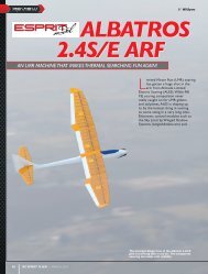
CENTRAGE<br />
CG LOCATION<br />
Centrage: A l’atelier, avion prêt au vol, porter le modèle sur les index de chaque côté du fuselage, à l’emplanture de l’aile, après avoir<br />
reporté les repères de centrage (voir schéma ci-dessous).<br />
Si le modèle penche vers l’avant (nez lourd) déplacer l’accu de propulsion vers l’arrière.<br />
Si le modèle penche vers l’arrière (queue lourde) déplacer l’accu de propulsion vers l’avant.<br />
L’avion est correctement centré quand il penche très légèrement vers l’avant avec les index pile-poil à cheval sur les<br />
repères.<br />
La position du CG détermine (entre autres) les caractéristiques du décrochage.<br />
CG=45 à 50mm du bord d’attaque de chaque côté du fuselage.<br />
Balance: In workshop, plane ready to fly, carry the model on the fingers on each side of the<br />
fuselage at the wing root, after having drawn the balance marks (see diagram below).<br />
If the model leans forwards (nose heavy), move the battery backwards.<br />
If the model leans backwards (tail heavy), move the battery forwards.<br />
The plane is correctly balanced when it leans very slightly forwards with the index on the<br />
reference marks.<br />
CG location determines (inter alia) the stall characteristics.<br />
CG=45-50mm measured from the leading edge to the wing center.<br />
45-50mm<br />
DEBATTEMENTS<br />
CONTROLS THROWS<br />
Course des ailerons<br />
Aileron stroke<br />
15mm<br />
10mm<br />
Course de la profondeur<br />
Elevator stroke<br />
9mm<br />
9mm<br />
Course de la direction<br />
Rudder stroke<br />
30mm<br />
30mm<br />
MIXAGES<br />
MIXING<br />
Mixage aérofreins donne profondeur<br />
Mixing from airbrakes to elevator<br />
Mixage: Volet de profondeur cabré environ 2mm quand les aérofreins sont sortis<br />
Mixing set: Elevator UP about 2mm when airbrakes extended<br />
2mm<br />
26
CONTROLES PRE-VOL<br />
PREFLIGHT CHECKS<br />
GENERALITES<br />
Centre de gravité: Equilibrez votre modèle avec le pack d’accu de propulsion installé, prêt à voler. Le choix du moteur, de la radio, des servos, du pack<br />
d’accu que vous utilisez conditionnent la masse finale et doivent être disposés dans le modèle avec discernement. Essayez d’équilibrer le modèle en déplaçant<br />
le pack d’accu et la réception avant d’ajouter du plomb.<br />
Commencer à voler avec le CG recommandé jusqu’à ce que vous soyez à l’aise avec votre avion. Vous pourrez trouver le nez un peu lourd au début mais<br />
c’est bien pour prendre contact. Ensuite, vous pourrez ajuster le CG en fonction de votre style de vol, en procédant petit pas par petit pas, particulièrement<br />
si vous le reculez. Déplacez le pack d’accu ou ajouter du plomb vers la queue ou le nez, si nécessaire.<br />
Pour les vols plus acrobatiques, un centrage plus arrière est meilleur. Pour un vol plus relax, un centrage plus avant est meilleur. Un avion avec le nez trop<br />
lourd ne vole pas bien, un peu comme un “camion” et est difficile à poser. Un avion centré trop arrière est incontrôlable et se traduit, le plus souvent, par<br />
un crash.<br />
Débattements des gouvernes: Les débattements doivent être réglés, autant que possible, de manière mécanique “pure” et affinés, ensuite, de manière<br />
électronique avec l’émetteur. Les débattements spécifiés ici, sont des valeurs de départ. Ils devront être ensuite ajustés en fonction de votre style de<br />
pilotage et de vos habitudes. Les valeurs d’exponentiels ne sont pas spécifiées, chaque pilote ayant vraiment ses préférences à ce niveau et elles sont<br />
directement liées aux valeurs des débattements, également. Les radios programmables permettent de changer radicalement le comportement d’un avion.<br />
Sachez les programmer et poursuivez les réglages jusqu’à ce que vous soyez complètement satisfait par les réactions de votre avion dans tous le domaine<br />
de vol.<br />
Moteur: Il doit fonctionner parfaitement à tous les régimes avec des reprises franches, du ralenti jusqu’à plein gaz, sans hoquet. Ne jamais voler avec un<br />
moteur qui n’est pas fiable et sur lequel vous avez un doute. Lire les instructions d’utilisation du moteur.<br />
Commandes de vol: S’assurer que toutes les gouvernes sont libres au niveau des articulations et qu’elles sont correctement centrées sur les plans<br />
fixes. Contrôler que toutes les charnières sont solidement fixées et ne peuvent en aucun cas sortir de leur logement. Les tringleries de commandes doivent<br />
être rigides, solides et ne doivent pas flamber. Vérifier le sens de débattement des ailerons, de la profondeur et de la direction. Des pilotes chevronnés ont<br />
perdu leur avion à cause d’ailerons inversés (!)<br />
Accus: Les accus de l’émetteur, du récepteur, de propulsion doivent être complètement chargés.<br />
Fixations: Contrôler le serrage de tous les boulons, vis de trappes, vis de capot, vis de servos, vis de guignols, contre-écrous de chapes, etc…<br />
Radio: Vérifier que tous les trims sont au neutre avec les volets des gouvernes parfaitement centrés. Contrôler les valeurs des débattements et la position<br />
correcte de tous les inter. Contrôler que l’antenne de réception est complètement déployée.<br />
Portée: Faire un essai de portée sans et avec le moteur en fonctionnement, en accord avec les instructions du fabricant de la radio.<br />
Si la portée est insuffisante ou si elle est réduite avec le moteur tournant, ne jamais voler avant d’avoir complètement résolu le problème!<br />
BALANCE:<br />
This is a very important relationship between the CG location and the stall characteristics of an airplane or<br />
knife-edge performance.<br />
An aft CG will make the plane snap roll instead of making a clean stall. And your plane goes to down side at<br />
knife-edge flying instead of straight.<br />
To measure the CG location, measure 45-50mm from the leading edge to wing center.<br />
CONTROL THROWS:<br />
Connect all your airborne equipment and turn on the radio system. Put your entire trim lever on the transmitter<br />
at the neutral position. Then make all of the control surface at neutral position. Hold them with scotch<br />
tapes. After you set everything at the neutral position, adjust the length of the pushrods for proper length.<br />
After connecting the pushrods to the servos and control surfaces, check to be sure that the surfaces move the<br />
amounts properly which is shown here. The elevator must not move more than 9mm each way. The rudder<br />
stroke should be 30mm each right and left and ailerons should be 15mm up and 10mm down.<br />
WING WEIGHT BALANCE:<br />
After adjsuting the down and side thrust of the motor, adjust the wing balance. Fly your model straight and<br />
level. Pull up and see which way your planes goes. If it goes to the right, put some weight on the left wing.<br />
Notice internet en couleur! :<br />
La notice est téléchargeable sur notre site sur la fiche produit du modèle section DOC-NOTICE.<br />
Internet construction guide in color! :<br />
The manual is downloadable on our website on the product page, section DOCUMENTATION.<br />
27


![P01(Oxalys EP) [更新済み].ai - Kyosho](https://img.yumpu.com/26948574/1/184x260/p01oxalys-ep-ai-kyosho.jpg?quality=85)