Guided Tour - AH1 Headset Transmitter - Samson
Guided Tour - AH1 Headset Transmitter - Samson
Guided Tour - AH1 Headset Transmitter - Samson

You also want an ePaper? Increase the reach of your titles
YUMPU automatically turns print PDFs into web optimized ePapers that Google loves.
<strong>Guided</strong> <strong>Tour</strong> - UM1 Receiver<br />
<strong>Samson</strong> AirLine<br />
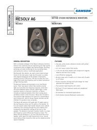
12: Level control - This knob sets the level of the audio signal being sent to the<br />
headphones output (see #13 below).<br />
13: Headphones output - Connect a stereo headphone to this standard 1/8" (3.5<br />
mm) mini-phone jack in order to monitor the signal being output by the UM1. We<br />
recommend the use of 30 ohm headphones. The level of the headphone signal can<br />
be set by adjusting the Level control (see #12 above). Maximum output is 240 mW @<br />
30 ohms).<br />
12<br />
13<br />
PHONES LEVEL<br />
BALANCED<br />
OUTPUT<br />
METER<br />
BATT.<br />
RF OFF<br />
14<br />
15<br />
ENGLISH<br />
14: Balanced output* - Use this electronically balanced low impedance (600 Ohm) mini-XLR jack when connecting the UM1 to professional<br />
(+4) audio equipment. Pin wiring is as follows: Pin 1 ground, Pin 2 high (hot), and Pin 3 low (cold).<br />
15: Meter switch - This three-position switch determines the function of the front-panel UM1 meter (see page #2 on page 9). In the left<br />
“RF” position, the meter indicates the strength of the incoming RF signal. In the center “BATTERY” position, the meter indicates relative battery<br />
power, showing whether the installed battery is at low (red), mid (yellow) or high (green) strength. (Note: When the red “low” indicator<br />
lights, performance is degraded and the battery needs to be replaced). In the right “OFF” position, the meter is disabled altogether, thus<br />
conserving battery power.<br />
* If required, both the unbalanced and balanced outputs can be used simultaneously.<br />
9