Guided Tour - AH1 Headset Transmitter - Samson
Guided Tour - AH1 Headset Transmitter - Samson
Guided Tour - AH1 Headset Transmitter - Samson

You also want an ePaper? Increase the reach of your titles
YUMPU automatically turns print PDFs into web optimized ePapers that Google loves.
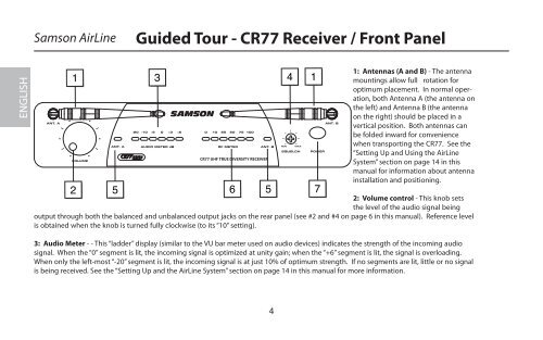
<strong>Samson</strong> AirLine<br />
<strong>Guided</strong> <strong>Tour</strong> - CR77 Receiver / Front Panel<br />
ENGLISH<br />
ANT. A<br />
1<br />
VOLUME<br />
2<br />
ANT. A<br />
-20<br />
-10<br />
-5<br />
3 4<br />
0 +3 +6<br />
AUDIO METER dB<br />
0 10 25 50 75 100<br />
RF METER<br />
5 5<br />
6<br />
1: Antennas (A and B) - The antenna<br />
mountings allow full rotation for<br />
optimum placement. In normal operation,<br />
both Antenna A (the antenna on<br />
the left) and Antenna B (the antenna<br />
on the right) should be placed in a<br />
vertical position. Both antennas can<br />
be folded inward for convenience<br />
when transporting the CR77. See the<br />
“Setting Up and Using the AirLine<br />
System” section on page 14 in this<br />
manual for information about antenna<br />
installation and positioning.<br />
2: Volume control - This knob sets<br />
the level of the audio signal being<br />
output through both the balanced and unbalanced output jacks on the rear panel (see #2 and #4 on page 6 in this manual). Reference level<br />
is obtained when the knob is turned fully clockwise (to its “10” setting).<br />
3: Audio Meter - - This “ladder” display (similar to the VU bar meter used on audio devices) indicates the strength of the incoming audio<br />
signal. When the “0” segment is lit, the incoming signal is optimized at unity gain; when the “+6” segment is lit, the signal is overloading.<br />
When only the left-most “-20” segment is lit, the incoming signal is at just 10% of optimum strength. If no segments are lit, little or no signal<br />
is being received. See the “Setting Up and the AirLine System” section on page 14 in this manual for more information.<br />
ANT. B<br />
CR77 UHF TRUE DIVERSITY RECEIVER<br />
MIN<br />
MAX<br />
SQUELCH<br />
1<br />
POWER<br />
7<br />
ANT. B<br />
4