1 - HJS-Internethandel
1 - HJS-Internethandel
1 - HJS-Internethandel

You also want an ePaper? Increase the reach of your titles
YUMPU automatically turns print PDFs into web optimized ePapers that Google loves.
ISTRUZIONI PER L’INSTALLAZIONE, L’USO E LA MANUTENZIONE - IT<br />
INSTRUCTIONS FOR INSTALLATION, USE AND MAINTENANCE - EN<br />
ANWEISUNGEN FÜR DIE AUFSTELLUNG, DEN GEBRAUCH UND DIE WARTUNG - DE<br />
INSTRUCTIONS POUR L’INSTALLATION, L’UTILISATION ET L’ENTRETIEN – FR<br />
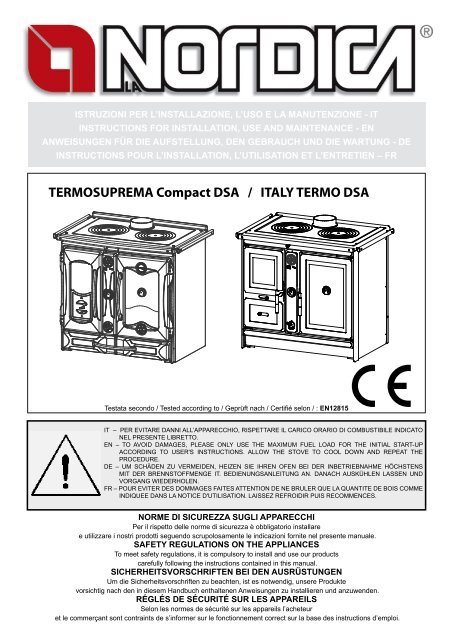
TERMOSUPREMA Compact DSA / ITALY TERMO DSA<br />
Testata secondo / Tested according to / Geprüft nach / Certifié selon / : EN12815|<br />
IT – PER EVITARE DANNI ALL’APPARECCHIO, RISPETTARE IL CARICO ORARIO DI COMBUSTIBILE INDICATO<br />
NEL PRESENTE LIBRETTO.<br />
EN – TO AVOID DAMAGES, PLEASE ONLY USE THE MAXIMUM FUEL LOAD FOR THE INITIAL START-UP<br />
ACCORDING TO USER'S INSTRUCTIONS. ALLOW THE STOVE TO COOL DOWN AND REPEAT THE<br />
PROCEDURE.<br />
DE – UM SCHÄDEN ZU VERMEIDEN, HEIZEN SIE IHREN OFEN BEI DER INBETRIEBNAHME HÖCHSTENS<br />
MIT DER BRENNSTOFFMENGE IT. BEDIENUNGSANLEITUNG AN. DANACH AUSKÜHLEN LASSEN UND<br />
VORGANG WIEDERHOLEN.<br />
FR – POUR EVITER DES DOMMAGES FAITES ATTENTION DE NE BRULER QUE LA QUANTITE DE BOIS COMME<br />
INDIQUEE DANS LA NOTICE D'UTILISATION. LAISSEZ REFROIDIR PUIS RECOMMENCES.<br />
NORME DI SICUREZZA SUGLI APPARECCHI<br />
Per il rispetto delle norme di sicurezza è obbligatorio installare<br />
e utilizzare i nostri prodotti seguendo scrupolosamente le indicazioni fornite nel presente manuale.<br />
SAFETY REGULATIONS ON THE APPLIANCES<br />
To meet safety regulations, it is compulsory to install and use our products<br />
carefully following the instructions contained in this manual.<br />
SICHERHEITSVORSCHRIFTEN BEI DEN AUSRÜSTUNGEN<br />
Um die Sicherheitsvorschriften zu beachten, ist es notwendig, unsere Produkte<br />
vorsichtig nach den in diesem Handbuch enthaltenen Anweisungen zu installieren und anzuwenden.<br />
RÉGLÉS DE SÉCURITÉ SUR LES APPAREILS<br />
Selon les normes de sécurité sur les appareils l’acheteur<br />
et le commerçant sont contraints de s’informer sur le fonctionnement correct sur la base des instructions d’emploi.
TERMOSUPREMA COMPACT DSA / ITALY TERMO DSA<br />
DICHIARAZIONE DI CONFORMITA’ DEL COSTRUTTORE<br />
Oggetto: Assenza di amianto e cadmio<br />
Si dichiara che tutti i nostri apparecchi vengono assemblati con materiali che non presentano parti di amianto o suoi derivati e che nel<br />
materiale d’apporto utilizzato per le saldature non è presente/utilizzato in nessuna forma il cadmio, come previsto dalla norma di riferimento.<br />
Oggetto: Regolamento CE n. 1935/2004<br />
Si dichiara che in tutti gli apparecchi da noi prodotti, i materiali destinati a venire a contatto con i cibi sono adatti all’uso alimentari, in<br />
conformità al Regolamento CE in oggetto.<br />
DECLARATION OF CONFORMITY OF THE MANUFACTURER<br />
Object: Absence of asbestos and cadmium<br />
We declare that the materials used for the assembly of all our appliances are without asbestos parts or asbestos derivates and that in the<br />
material used for welding, cadmium is not present, as prescribed in relevant norm.<br />
Object: CE n. 1935/2004 regulation.<br />
We declare that in all products we produce, the materials which will get in touch with food are suitable for alimentary use, according to the<br />
a.m. CE regulation.<br />
KONFORMITÄTSERKLÄRUNG DES HERSTELLERS<br />
Betreff: Fehlen von Asbest und Kadmium<br />
Wir bestätigen, dass die verwendeten Materialen oder Teilen für die Herstellung der La Nordica Geräte ohne Asbest und Derivat sind und<br />
auch das Lot für das Schweißen immer ohne Kadmium ist.<br />
Betreff: Ordnung CE n. 1935/2004.<br />
Wir erklären in alleiniger Verantwortung, dass die Materialen der Teile, die für den Kontakt mit Lebensmitteln vorgesehen sind, für die<br />
Nahrungsbenutzung geeignet sind und der Richtlinien CE n. 1935/2004 erfüllen.<br />
DÉCLARATION DE CONFORMITÉ DU CONSTRUCTEUR<br />
Objet: Absence d’amiante et de cadmium<br />
Nous déclarons que tous nos appareils sont assemblés avec des matériaux ne comportant pas de parties en amiante ou ses dérivés et<br />
que dans le matériau d’apport utilisé pour les soudures le cadmium n’est pas présent ni utilisé sous aucune forme que ce soit, comme il<br />
est prévu par la norme de référence.<br />
Objet: Règlement CE n. 1935/2004<br />
Nous déclarons que tous nos produits, les matériaux destinés à entrer en contact avec les aliments sont indiqués pour l’usage des<br />
aliments, conformément au Règlement CE cité à l’objet.<br />
2 7095802 - Rev.07 - 05/2011 - IT-EN-DE-FR
TERMOSUPREMA COMPACT DSA / ITALY TERMO DSA<br />
IT - INDICE<br />
1. AVVERTENZE GENERALI ..........................................................................................................................................................................5<br />
2. NORME PER L’INSTALLAZIONE.................................................................................................................................................................5<br />
2.1. Vaso di espansione APERTO..........................................................................................................................................................................5<br />
2.2. Vaso di espansione CHIUSO...........................................................................................................................................................................6<br />
2.3. VALVOLA MISCELATRICE TERMOSTATICA AUTOMATICA (OPTIONAL)....................................................................................................6<br />
2.4. VALVOLA SCARICO TERMICO (OPTIONAL).................................................................................................................................................6<br />
2.5. COLLEGAMENTO E CARICO DELL’IMPIANTO............................................................................................................................................7<br />
3. SICUREZZA ANTINCENDIO........................................................................................................................................................................7<br />
3.1. PRONTO INTERVENTO.................................................................................................................................................................................7<br />
4. DESCRIZIONE TECNICA.............................................................................................................................................................................7<br />
5. CANNA FUMARIA.........................................................................................................................................................................................8<br />
5.1. COMIGNOLO..................................................................................................................................................................................................8<br />
5.2. COLLEGAMENTO AL CAMINO......................................................................................................................................................................9<br />
5.3. COLLEGAMENTO ALLA CANNA FUMARIA DI UN CAMINETTO O FOCOLARE APERTO..........................................................................9<br />
6. AFFLUSSO D’ARIA NEL LUOGO D’INSTALLAZIONE DURANTE LA COMBUSTIONE.............................................................................9<br />
7. COMBUSTIBILI AMMESSI / NON AMMESSI...............................................................................................................................................9<br />
8. ACCENSIONE............................................................................................................................................................................................10<br />
8.1. FUNZIONAMENTO NORMALE..................................................................................................................................................................... 11<br />
8.2. USO DEL FORNO (dove presente)............................................................................................................................................................... 11<br />
8.3. MANCANZA DI ENERGIA ELETTRICA.........................................................................................................................................................12<br />
8.4. FUNZIONAMENTO NEI PERIODI DI TRANSIZIONE...................................................................................................................................12<br />
8.5. UTILIZZO COME NORMALE CUCINA.........................................................................................................................................................12<br />
9. FERMO ESTIVO.........................................................................................................................................................................................12<br />
10. MANUTENZIONE E CURA.........................................................................................................................................................................12<br />
10.1. PULIZIA CANNA FUMARIA...........................................................................................................................................................................12<br />
10.2. PULIZIA VETRO............................................................................................................................................................................................13<br />
10.3. PULIZIA CASSETTO CENERE.....................................................................................................................................................................13<br />
10.4. MANUTENZIONE DELL’IMPIANTO IDRAULICO.........................................................................................................................................13<br />
11. FERMO ESTIVO.........................................................................................................................................................................................13<br />
12. DATI TECNICI.............................................................................................................................................................................................14<br />
13. SCHEMA DI INSTALLAZIONE / INSTALLATION LAY-OUT / ALLGEMEINES INSTALLATIONSSCHEMA THERMOKÜCHE /<br />
INSTALLATION SCHEME...........................................................................................................................................................................45<br />
14. SCHEDA TECNICA / TECHNICAL DATA SHEET / TECHNISCHES DATENBLATT / FICHE TECHNIQUE..............................................50<br />
EN - CONTENTS<br />
1. GENERAL PRECAUTIONS........................................................................................................................................................................15<br />
2. INSTALLATION REGULATIONS................................................................................................................................................................15<br />
2.1. OPEN expansion Tank system......................................................................................................................................................................15<br />
2.2. CLOSED expansion Tank system..................................................................................................................................................................16<br />
2.3. AUTOMATIC THERMOSTATIC MIXER VALVE - (OPTIONAL).....................................................................................................................16<br />
2.4. HEAT DISCHARGE VALVE - (OPTIONAL) ..................................................................................................................................................16<br />
2.5. SYSTEM CONNECTION AND FILLING........................................................................................................................................................17<br />
3. FIRE SAFETY.............................................................................................................................................................................................17<br />
3.1. IN A EMERGENCY........................................................................................................................................................................................17<br />
4. TECHNICAL DESCRIPTION......................................................................................................................................................................17<br />
5. FLUE...........................................................................................................................................................................................................18<br />
5.1. CHIMNEY POT..............................................................................................................................................................................................18<br />
5.2. CONNECTION TO THE CHIMNEY...............................................................................................................................................................18<br />
5.3. CONNECTING A FIREPLACE OR OPEN HEARTH TO THE FLUE.............................................................................................................19<br />
6. AIR FLOW IN THE PLACE OF INSTALLATION DURING COMBUSTION ................................................................................................19<br />
7. PERMITTED/FORBIDDEN FUELS.............................................................................................................................................................19<br />
8. IGNITION....................................................................................................................................................................................................20<br />
8.1. NORMAL OPERATION..................................................................................................................................................................................21<br />
8.2. OVEN USE (if present)..................................................................................................................................................................................21<br />
8.3. ELECTRICAL POWER SUPPLY FAILURE...................................................................................................................................................22<br />
8.4. OPERATION IN TRANSITION PERIODS.....................................................................................................................................................22<br />
8.5. NORMAL COOKER USE..............................................................................................................................................................................22<br />
9. SUMMER TIME...........................................................................................................................................................................................22<br />
10. MAINTENANCE AND CARE......................................................................................................................................................................22<br />
10.1. FLUE CLEANING..........................................................................................................................................................................................22<br />
10.2. GLASS CLEANING.......................................................................................................................................................................................23<br />
10.3. ASH DRAWER CLEANING...........................................................................................................................................................................23<br />
10.4. MAINTENANCE ON THE WATER SYSTEM.................................................................................................................................................23<br />
11. SUMMER SET ASIDE.................................................................................................................................................................................23<br />
12. TECHNICAL DATA......................................................................................................................................................................................24<br />
13. SCHEMA DI INSTALLAZIONE / INSTALLATION LAY-OUT / ALLGEMEINES INSTALLATIONSSCHEMA THERMOKÜCHE /<br />
INSTALLATION SCHEME...........................................................................................................................................................................45<br />
14. SCHEDA TECNICA / TECHNICAL DATA SHEET / TECHNISCHES DATENBLATT / FICHE TECHNIQUE..............................................50<br />
7095802 - Rev.07 - 05/2011 - IT-EN-DE-FR 3
TERMOSUPREMA COMPACT DSA / ITALY TERMO DSA<br />
DE - INHALTSVERZEICHNIS<br />
1. ALLGEMEINE HINWEISE .........................................................................................................................................................................25<br />
2. INSTALLATIONSVORSCHRIFTEN ...........................................................................................................................................................25<br />
2.1. OFFENEM Ausdehnungsgefäß.....................................................................................................................................................................25<br />
2.2. GESCHLOSSENEM Ausdehnungsgefäß .....................................................................................................................................................26<br />
2.3. AUTOMATISCHES THERMOSTAT- MISCHVENTIL (OPTIONAL) ..............................................................................................................26<br />
2.4. WÄRMEABLASSVENTIL (OPTIONAL) ........................................................................................................................................................27<br />
2.5. VERBINDUNG UND LADEN DER ANLAGE.................................................................................................................................................27<br />
3. BRANDSCHUTZ.........................................................................................................................................................................................27<br />
3.1. SOFORTIGES EINSCHREITEN...................................................................................................................................................................27<br />
4. TECHNISCHE BESCHREIBUNG...............................................................................................................................................................27<br />
5. RAUCHABZUG...........................................................................................................................................................................................28<br />
5.1. SCHORNSTEINPOSITION...........................................................................................................................................................................29<br />
5.2. ANSCHLUSS AN DEN SCHORNSTEIN.......................................................................................................................................................29<br />
5.3. ANSCHLUSS AN DEN RAUCHABZUG EINES OFFENEN KAMINS...........................................................................................................29<br />
6. LUFTZUSTROM AM INSTALLATIONSORT WÄHREND DER VERBRENNUNG......................................................................................29<br />
7. ZULÄSSIGE / UNZULÄSSIGE BRENNSTOFFE........................................................................................................................................30<br />
8. ANZÜNDEN................................................................................................................................................................................................30<br />
8.1. NORMALER BETRIEB..................................................................................................................................................................................31<br />
8.2. BENUTZUNG DES BACKOFENS (wenn anwesend)...................................................................................................................................32<br />
8.3. STROMAUSFALL..........................................................................................................................................................................................32<br />
8.4. BETRIEB IN DER ÜBERGANGSZEIT..........................................................................................................................................................32<br />
8.5. VERWENDUNG ALS NORMALER HERD....................................................................................................................................................32<br />
9. SOMMERLICHE STILLEGUNG.................................................................................................................................................................32<br />
10. INSTANDHALTUNG UND PFLEGE............................................................................................................................................................33<br />
10.1. REINIGUNG DES RAUCHABZUGS.............................................................................................................................................................33<br />
10.2. REINIGUNG DER GLASSCHEIBE...............................................................................................................................................................33<br />
10.3. REINIGUNG DES ASCHEKASTENS............................................................................................................................................................33<br />
10.4. WARTUNG DER HYDRAULIKANLAGE........................................................................................................................................................33<br />
11. STILLSTAND IM SOMMER........................................................................................................................................................................33<br />
12. TECHNISCHE DATEN................................................................................................................................................................................34<br />
13. SCHEMA DI INSTALLAZIONE / INSTALLATION LAY-OUT / ALLGEMEINES INSTALLATIONSSCHEMA THERMOKÜCHE /<br />
INSTALLATION SCHEME...........................................................................................................................................................................45<br />
14. SCHEDA TECNICA / TECHNICAL DATA SHEET / TECHNISCHES DATENBLATT / FICHE TECHNIQUE..............................................50<br />
FR - TABLE DES MATIÈRES<br />
1. AVERTISSEMENTS GENERAUX..............................................................................................................................................................35<br />
2. REGLES POUR LA MISE EN PLACE........................................................................................................................................................35<br />
2.1. Vase d’expansion OUVERT..........................................................................................................................................................................35<br />
2.2. Vase d’expansion FERME.............................................................................................................................................................................36<br />
2.3. VANNE MELANGEUSE THERMOSTATIQUE AUTOMATIQUE (OPTION) ..................................................................................................36<br />
2.4. VANNE D’ÉVACUATION THERMIQUE (OPTION) .......................................................................................................................................36<br />
2.5. RACCORDEMENT ET CHARGEMENT DE L’INSTALLATION ....................................................................................................................37<br />
3. SÉCURITÉ CONTRE LES INCENDIES.....................................................................................................................................................37<br />
3.1. INTERVENTION RAPIDE..............................................................................................................................................................................37<br />
4. DESCRIPTION TECHNIQUE.....................................................................................................................................................................37<br />
5. CONDUIT DE LA CHEMINÉE.....................................................................................................................................................................38<br />
5.1. POSITION DU POT DE LA CHEMINÉE........................................................................................................................................................38<br />
5.2. CONNEXION AVEC LA CHEMINÉE.............................................................................................................................................................39<br />
5.3. CONNEXION AU CONDUIT DE FUMÉE D’UNE CHEMINÉE OU D’UN FOYER OUVERT.........................................................................39<br />
6. AMENÉE D’AIR DANS LE LIEU DE LA MISE EN PLACE DURANT LA COMBUSTION...........................................................................39<br />
7. COMBUSTIBLES ADMIS / NON ADMIS....................................................................................................................................................39<br />
8. MISE A FEU................................................................................................................................................................................................40<br />
8.1. FONCTIONNEMENT NORMAL.....................................................................................................................................................................41<br />
8.2. EMPLOI DU FOUR........................................................................................................................................................................................41<br />
8.3. MANQUE D’ÉNERGIE ÉLECTRIQUE..........................................................................................................................................................42<br />
8.4. FONCTIONNEMENT DANS LES PÉRIODES TRANSITOIRES...................................................................................................................42<br />
8.5. UTILISATION COMME UNE CUISINIÈRE NORMALE.................................................................................................................................42<br />
9. ARRÊT PENDANT L’ÉTÉ...........................................................................................................................................................................42<br />
10. ENTRETIEN ET SOIN................................................................................................................................................................................42<br />
10.1. NETTOYAGE DU CONDUIT DE FUMÉE......................................................................................................................................................42<br />
10.2. NETTOYAGE DE LA VITRE..........................................................................................................................................................................43<br />
10.3. NETTOYAGE DU TIROIR A CENDRES........................................................................................................................................................43<br />
10.4. ENTRETIEN DE L’INSTALLATION HYDRAULIQUE.....................................................................................................................................43<br />
11. ARRÊT PENDANT L’ÉTÉ...........................................................................................................................................................................43<br />
12. DONNÉES TECHNIQUES..........................................................................................................................................................................44<br />
13. SCHEMA DI INSTALLAZIONE / INSTALLATION LAY-OUT / ALLGEMEINES INSTALLATIONSSCHEMA THERMOKÜCHE /<br />
INSTALLATION SCHEME...........................................................................................................................................................................45<br />
14. SCHEDA TECNICA / TECHNICAL DATA SHEET / TECHNISCHES DATENBLATT / FICHE TECHNIQUE..............................................50<br />
4 7095802 - Rev.07 - 05/2011 - IT-EN-DE-FR
TERMOSUPREMA COMPACT DSA / ITALY TERMO DSA<br />
1. AVVERTENZE GENERALI<br />
La responsabilità de La NORDICA S.p.A. è limitata alla fornitura dell’apparecchio.<br />
Il suo impianto va realizzato in modo conforme alla regola dell’arte, secondo le prescrizioni delle presenti istruzioni e le regole della<br />
professione, da personale qualificato, che agisce a nome di imprese adatte ad assumere l’intera responsabilità dell’insieme dell’impianto.<br />
La NORDICA S.p.A. non è responsabile del prodotto modificato senza autorizzazione e tanto meno per l’uso di ricambi non<br />
originali.<br />
2. NORME PER L’INSTALLAZIONE<br />
L’installazione del termoprodotto e degli equipaggiamenti ausiliari, relativi all’impianto di riscaldamento, deve essere conforme a tutte le<br />
Norme e Regolamentazioni attuali ed a quanto previsto dalla Legge.<br />
L’installazione, i relativi collegamenti dell’impianto, la messa in servizio e la verifica del corretto funzionamento devono essere eseguiti<br />
a regola d’arte da personale professionalmente preparato nel pieno rispetto delle norme vigenti, sia nazionali, regionali, provinciali e<br />
comunali presenti nel paese in cui è stato installato l’apparecchio, nonché delle presenti istruzioni.<br />
L’installazione deve essere eseguita da personale autorizzato, che dovrà rilasciare all’acquirente una dichiarazione di conformità<br />
dell’impianto, il quale si assumerà l’intera responsabilità dell’installazione definitiva e del conseguente buon funzionamento del prodotto<br />
installato.<br />
NON SI POSSONO EFFETTUARE MODIFICHE ALL’APPARECCHIO. Non vi sarà responsabilità da parte di La NORDICA S.p.A. in<br />
caso di mancato rispetto di tali precauzioni.<br />
Prima dell’installazione, si consiglia di effettuare un lavaggio accurato di tutte le tubazioni dell’impianto onde rimuovere eventuali residui<br />
che potrebbero compromettere il buon funzionamento del termoprodotto.<br />
IMPORTANTE:<br />
a) In caso di fuoriuscite d’acqua chiudere l’alimentazione idrica ed avvisare con sollecitudine il servizio tecnico di assistenza;<br />
b) La pressione di esercizio dell’impianto deve essere periodicamente controllata.<br />
c) In caso di non utilizzo della caldaia per un lungo periodo è consigliabile l’intervento del servizio tecnico di assistenza per effettuare<br />
almeno le seguenti operazioni:<br />
• chiudere i rubinetti dell’acqua sia dell’impianto termico sia del sanitario;<br />
• svuotare l’impianto termico e sanitario se c’è rischio di gelo.<br />
La NORDICA S.p.A. declina ogni responsabilità per danni a cose e/o persone provocati dall’impianto. Inoltre non è responsabile<br />
del prodotto modificato senza autorizzazione e tanto meno per l’uso di ricambi non originali.<br />
Il Vostro abituale spazzacamino di zona deve essere informato sull’installazione del termoprodotto, affinché possa verificarne il regolare<br />
collegamento alla canna fumaria ed il grado di efficienza di quest’ultima.<br />
Prima dell’installazione eseguire le seguenti verifiche:<br />
• accertarsi che il pavimento possa sostenere il peso dell’apparecchio e provvedere ad un adeguato isolamento nel caso sia costruito<br />
in materiale infiammabile.<br />
• assicurarsi che nella stanza dove sarà installato vi sia una ventilazione adeguata (presenza di presa d’aria vedi capitolo 6)<br />
• evitare l’installazione in locali con presenza di condotti di ventilazione collettivo, cappe con o senza estrattore, apparecchi a gas<br />
di tipo B, pompe di calore o la presenza di apparecchi il cui funzionamento contemporaneo possa mettere in depressione il locale<br />
(rif. Norma UNI 10683/98)<br />
• accertarsi che la canna fumaria e i tubi a cui verrà collegato l’apparecchio siano idonei al funzionamento dello stesso.<br />
• l diametro dell’apertura per il collegamento al camino deve corrispondere per lo meno al diametro del tubo fumo. L’apertura<br />
dovrebbe essere dotata di una connessione a muro per l’inserimento del tubo di scarico e di un rosone.<br />
• Il foro di scarico fumi non utilizzato deve essere ricoperto con il relativo tappo (cap. 14 a pagina 50 pos.7).<br />
I termoprodotti modello DSA possono essere installati sia in un impianto a VASO di espansione APERTO (cap.2.1) sia in un impianto a<br />
VASO di espansione CHIUSO (cap.2.2).<br />
2.1. Vaso di espansione APERTO<br />
L’impianto con vaso di espansione aperto, deve essere OBBLIGATORIAMENTE provvisto di:<br />
1. VASO DI ESPANSIONE APERTO: vaso avente una capacità pari al 10 % del contenuto d’acqua totale del termoprodotto e dell’impianto.<br />
Il vaso va posizionato nel punto più alto dell’impianto almeno 2 m sopra il radiatore posto al livello più alto.<br />
2. TUBO DI SICUREZZA : tubo che collega per la via più breve, senza tratti discendenti o sifonanti la mandata del termoprodotto con la<br />
parte superiore del vaso di espansione aperto. Il tubo di sicurezza deve avere la sezione minima interna di 1’’gas.<br />
3. TUBO DI CARICO : tubo che collega il fondo del vaso di espansione aperto con il tubo di ritorno dell’impianto. La sezione minima<br />
deve essere di ¾”gas. Tutti questi elementi non devono per nessuna ragione avere organi di intercettazione interposti che possano<br />
accidentalmente escluderli e devono essere posizionati in ambienti non esposti al gelo poiché, se dovessero gelare, si potrebbe<br />
verificare la rottura o addirittura l’esplosione del corpo caldaia. In caso di esposizione al gelo sarà opportuno aggiungere all’acqua<br />
dell’impianto una adeguata percentuale di liquido antigelo che consentirà di eliminare completamente il problema. In nessun modo ci<br />
dovrà essere circolazione d’acqua nel vaso di espansione aperto fra il tubo di sicurezza ed il tubo di carico. Questa provocherebbe<br />
l’ossigenazione dell’acqua e la conseguente corrosione del termoprodotto e dell’impianto in tempi molto brevi<br />
4. VALVOLA DI SCARICO TERMICO: costituisce una ulteriore sicurezza positiva in grado di prevenire l’ebollizione anche in assenza<br />
di energia elettrica. E’ costituita da un corpo valvola simile ad una valvola di sicurezza a pressione che, a differenza di questa, si apre<br />
al raggiungimento di una temperatura pretarata ( di solito 94 – 95° C ) scaricando dalla mandata dell’impianto acqua calda che verrà<br />
sostituita con altrettanta acqua fredda proveniente attraverso il tubo di carico del vaso di espansione aperto smaltendo in questo modo<br />
il calore eccessivo<br />
5. VALVOLA DI SICUREZZA da 1,5 bar: la massima pressione di esercizio ammessa per l’impianto è di 1,5 bar (pari a 15 m di colonna<br />
d’acqua), pressioni superiori possono provocare deformazioni e rotture al corpo caldaia.<br />
7095802 - Rev.07 - 05/2011 - IT-EN-DE-FR 5
TERMOSUPREMA COMPACT DSA / ITALY TERMO DSA<br />
6. ALTRI DISPOSITIVI di sicurezza previsti dalla Normativa vigente in materia.<br />
7. POMPA DI CIRCOLAZIONE : deve essere preferibilmente montata sul ritorno per evitare che possa disinnescarsi a temperature<br />
dell’acqua molto elevate, accertarsi però che non faccia circolare l’acqua nel vaso di espansione aperto altrimenti provocherebbe una<br />
continua ossigenazione dell’acqua con conseguente, rapida, corrosione del corpo caldaia. La sua prevalenza deve essere tale da non<br />
provocare una circolazione forzata nel vaso di espansione aperto. Deve inoltre essere collegata ad un termostato o alla centralina<br />
elettronica fornita come OPTIONAL.<br />
8. VALVOLA MISCELATRICE TERMOSTATICA AUTOMATICA – (vedi capitolo 2.3)<br />
IMPORTANTE: i sensori di sicurezza della temperatura devono essere a bordo macchina o a una distanza non maggiore di 30 cm dal<br />
collegamento di mandata del termoprodotto. Qualora i termoprodotti non siano provvisti di tutti i dispostivi, quelli mancanti possono<br />
essere installati sulla tubazione di mandata del termoprodotto entro una distanza dal termoprodotto non maggiore di 1 m.<br />
ATTENZIONE: Per nessuna ragione si deve accendere il fuoco se prima l’impianto non sia stato completamente riempito d’acqua;<br />
il farlo comporterebbe un danneggiamento gravissimo di tutta la struttura. Il riempimento dell’impianto deve essere fatto tramite<br />
il tubo di carico direttamente nella vaschetta del vaso di espansione aperto in modo da evitare che una eccessiva pressione della rete<br />
idrica deformi il corpo caldaia.<br />
L’impianto va tenuto costantemente pieno d’acqua anche nei periodi in cui non è richiesto l’uso. Durante il periodo invernale un’eventuale<br />
non attività va affrontata con l’aggiunta di sostanze antigelo.<br />
2.2. Vaso di espansione CHIUSO<br />
L’impianto con vaso di espansione CHIUSO, deve essere OBBLIGATORIAMENTE provvisto di:<br />
1. VALVOLA DI SICUREZZA da 3 bar: la massima pressione di esercizio ammessa per l’impianto è di 3 bar (pari a 30 m di colonna<br />
d’acqua), pressioni superiori possono provocare deformazioni e rotture del corpo caldaia.<br />
2. VALVOLA MISCELATRICE TERMOSTATICA AUTOMATICA – (vedi capitolo 2.3)<br />
3. VALVOLA DI SCARICO TERMICO o SCARICO DI SICUREZZA TERMICA (a sicurezza positiva, cioè in caso di guasto della valvola<br />
questa continua a scaricare lo stesso)<br />
4. VASO DI ESPANSIONE CHIUSO<br />
5. TERMOSTATO DI COMANDO DEL CIRCOLATORE<br />
6. TERMOSTATO DI ATTIVAZIONE DELL’ALLARME ACUSTICO<br />
7. ALLARME ACUSTICO<br />
8. INDICATORE DI TEMPERATURA<br />
9. INDICATORE DI PRESSIONE<br />
10. SISTEMA DI CIRCOLAZIONE<br />
IMPORTANTE: i sensori di sicurezza della temperatura devono essere a bordo macchina o a una distanza non maggiore di 30 cm dal<br />
collegamento di mandata del termoprodotto. Qualora i termoprodotti non siano provvisti di tutti i dispostivi, quelli mancanti possono<br />
essere installati sulla tubazione di mandata del termoprodotto entro una distanza dal termoprodotto non maggiore di 1 m.<br />
OBBLIGATORIAMENTE i termoprodotti per il riscaldamento di tipo domestico inseriti in impianti di riscaldamento a VASO CHIUSO<br />
devono essere dotati, al loro interno, di un circuito di raffreddamento predisposto dal costruttore dell’apparecchio, attivato da una valvola<br />
di sicurezza termica (vedi capitolo 2.4) che non richieda energia ausiliaria e tale da garantire che non venga superata la temperatura<br />
limite imposta dalla norma. Il collegamento tra il gruppo di alimentazione e la valvola deve essere privo di intercettazioni. La pressione a<br />
monte del circuito di raffreddamento deve essere di almeno 1,5 bar.<br />
2.3. VALVOLA MISCELATRICE TERMOSTATICA AUTOMATICA (OPTIONAL)<br />
La valvola miscelatrice termostatica automatica trova applicazione nei termoprodotti a combustibile solido in quanto previene il ritorno di<br />
acqua fredda nello scambiatore. Figura 4 a pagina 52<br />
Le tratte 1 e 3 sono sempre aperte e, assieme alla pompa installata sul ritorno (R), garantiscono la circolazione dell’acqua all’interno dello<br />
scambiatore della caldaia a biomassa (CB).<br />
Una elevata temperatura di ritorno permette di migliorare l’efficienza, riduce la formazione di condensa dei fumi e allunga la vita della<br />
caldaia. Le valvole in commercio presentano svariate tarature, La NORDICA consiglia l’utilizzo del modello 55°C con connessioni idrauliche<br />
da 1”. Una volta raggiunta la temperatura di taratura della valvola, viene aperta la tratta 2 e l’acqua della caldaia va all’impianto attraverso<br />
la mandata (M).<br />
IMPORTANTE la mancata installazione del dispositivo fa decadere la garanzia dello scambiare di calore.<br />
2.4. VALVOLA SCARICO TERMICO (OPTIONAL)<br />
I termoprodotti a combustibile solido devono essere installati con le sicurezze previste dalle vigenti leggi in materia.<br />
A tale scopo la termostufa è munita di uno serpentino di scarico termico. ( Pos. 6 Cap. 14 a pagina 50)<br />
Il serpentino di scarico termico dovrà essere collegato da un lato alla rete idrica (A) e dall’altro alla rete di drenaggio (C). La valvola di<br />
scarico termico, il cui bulbo andrà collegato all’attacco B, al raggiungimento della temperatura di sicurezza abilita l’ingresso di acqua<br />
fredda nel serpentino contenuto nella caldaia, scaricando l’eccesso termico tramite il tubo C verso uno scarico opportunamente installato.<br />
La pressione a monte del circuito di raffreddamento deve essere di almeno 1,5 bar.<br />
6 7095802 - Rev.07 - 05/2011 - IT-EN-DE-FR
TERMOSUPREMA COMPACT DSA / ITALY TERMO DSA<br />
2.5. COLLEGAMENTO E CARICO DELL’IMPIANTO<br />
Alcuni esempi, puramente indicativi dell’impianto, sono riportati al capitolo 13, mentre i collegamenti al termoprodotto sono riportati al<br />
capitolo 14 .<br />
ATTENZIONE :Il riempimento dell’impianto deve avvenire esclusivamente per caduta naturale dell’acqua dal vaso di espansione<br />
aperto attraverso il tubo di carico per evitare che una pressione di rete troppo elevata dell’acquedotto possa deformare o far<br />
scoppiare il corpo caldaia.<br />
Durante questa fase aprire tutti gli sfiati dei termosifoni per evitare formazioni di sacche d’aria, sorvegliando poi la fuori uscita d’acqua per<br />
evitare spiacevoli allagamenti.<br />
Il collaudo di tenuta dell’impianto va eseguito con la pressione del vaso di espansione aperto.<br />
L’impianto va tenuto costantemente pieno d’acqua anche nei periodi in cui non è richiesto l’uso del termoprodotto. Durante il<br />
periodo invernale un’eventuale non attività va affrontata con l’aggiunta di sostanze antigelo.<br />
3. SICUREZZA ANTINCENDIO<br />
Nell’installazione del prodotto devono essere osservate le seguenti misure di sicurezza:<br />
d) Al fine di assicurare un sufficiente isolamento termico, rispettare la distanza minima di sicurezza dal retro e da entrambi i lati da<br />
elementi costruttivi ed oggetti infiammabili e sensibili al calore (mobili, rivestimenti di legno, stoffe ecc.) (vedi Figura 2 a pagina 51<br />
- A). Tutte le distanze minime di sicurezza sono indicate sulla targhetta tecnica del prodotto e NON si deve scendere al di<br />
sotto dei valori indicati;<br />
e) davanti alla porta del focolare, nell’area di radiazione della stessa, non deve esserci alcun oggetto o materiale di costruzione<br />
infiammabile e sensibile al calore a meno di 100 cm di distanza. Tale distanza può essere ridotta a 40 cm qualora venga installata<br />
una protezione, retroventilata e resistente al calore, davanti all’intero componente da proteggere;<br />
f) qualora il prodotto venga installato su un pavimento di materiale infiammabile, bisogna prevedere un sottofondo ignifugo.<br />
I pavimenti in materiale infiammabile, come moquette, parquet o sughero etc., devono essere sostituiti da uno strato di<br />
materiale non infiammabile, ad esempio ceramica, pietra, vetro o acciaio etc. (dimensioni secondo l’ordinamento regionale). Il<br />
sottofondo deve sporgere frontalmente di almeno 50 cm e lateralmente di almeno altri 30 cm oltre all’apertura della porta di carico<br />
(vedi Figura 2 a pagina 51 - B);<br />
g) sopra al prodotto non devono essere presenti componenti infiammabili (es. mobili - pensili).<br />
Il prodotto deve funzionare esclusivamente con il cassetto cenere inserito. I residui solidi della combustione (ceneri) devono essere raccolti<br />
in un contenitore ermetico e resistente al fuoco. Il prodotto non deve mai essere acceso in presenza di emissioni gassose o vapori (per<br />
esempio colla per Linoleum, benzina ecc.). Non depositate materiali infiammabili nelle vicinanze del prodotto .<br />
Durante la combustione viene sprigionata energia termica che comporta un marcato riscaldamento delle superfici, di porte, maniglie,<br />
comandi, vetri, tubo fumi ed eventualmente della parte anteriore dell’apparecchio. Evitate il contatto con tali elementi senza un<br />
corrispondente abbigliamento protettivo o senza utensili accessori (guanti resistenti al calore, dispositivi di comando).<br />
Fate in modo che i bambini siano consapevoli di questi pericoli e teneteli lontani dal focolare durante il suo funzionamento.<br />
Quando si utilizza un combustibile errato o troppo umido si potrebbero formare dei depositi (creosoto) nella canna fumaria con possibile<br />
incendio della stessa.<br />
3.1. PRONTO INTERVENTO<br />
Se si manifesta un incendio nel collegamento o nella canna fumaria :<br />
a) Chiudere la porta di caricamento e del cassetto cenere.<br />
b) Chiudere i registri dell’aria comburente<br />
c) Spegnere tramite l’uso di estintori ad anidride carbonica ( CO 2<br />
a polveri )<br />
d) Richiedere l’immediato intervento dei Vigili del Fuoco<br />
NON SPEGNERE IL FUOCO CON L’USO DI GETTI D’ACQUA.<br />
Quando la canna fumaria smette di bruciare farla verificare da uno specialista per individuare eventuali crepe o punti permeabili.<br />
4. DESCRIZIONE TECNICA<br />
I termoprodotti La Nordica si addicono a riscaldare spazi abitativi dotati di un impianto di riscaldamento centralizzato costituito da radiatori<br />
o da termoconvettori sostituendo del tutto o in parte la tradizionale caldaia a gas o gasolio. Esse sono ideali per appartamenti di vacanza<br />
e case del fine settimana oppure come riscaldamento ausiliario durante tutto l’anno.<br />
Come combustibili vengono utilizzati ceppi di legna.<br />
La termocucina è costituita di lastre in lamiera d’acciaio zincata, ghisa smaltata. Il focolare si trova all’interno della caldaia costruita con<br />
acciaio di 4 mm di spessore e rinforzata con chiodi saldati. Nella caldaia circola l’acqua dell’impianto di riscaldamento la quale assorbe il<br />
calore prodotto nel focolare. All’interno del focolare si trova una griglia piana regolabile in altezza.<br />
Il focolare è dotato di una porta panoramica con vetro ceramico (resistente fino a 700°C). Questo consente un’affascinante vista sulle<br />
fiamme ardenti. Inoltre viene così impedita ogni possibile fuori uscita di scintille e fumo.<br />
Il riscaldamento dell’ambiente avviene:<br />
a) per irraggiamento: attraverso il vetro panoramico e le superfici esterne calde del termoprodotto viene irraggiato calore nell’ambiente.<br />
b) per conduzione: mediante i radiatori o termoconvettori dell’impianto centralizzato alimentati dall’acqua calda generata dal<br />
termoprodotto.<br />
Il termoprodotto è fornito di registri per l’aria primaria e secondaria e di un termostato, con i quali viene regolata l’aria di combustione.<br />
7095802 - Rev.07 - 05/2011 - IT-EN-DE-FR 7
TERMOSUPREMA COMPACT DSA / ITALY TERMO DSA<br />
Registro Aria PRIMARIA (Figura 1 a pagina 51 pos. A).<br />
Con il registro inferiore viene regolato il passaggio dell’aria primaria nella parte bassa attraverso il cassetto cenere e la griglia in direzione<br />
del combustibile. L’aria primaria è necessaria per il processo di combustione. Il cassetto cenere deve essere svuotato regolarmente, in<br />
modo che la cenere non ostacoli l’entrata dell’aria per la combustione. Attraverso l’aria primaria viene anche mantenuto vivo il fuoco.<br />
Il registro dell’aria primaria deve essere aperto appena un po’ durante la combustione della legna, poiché altrimenti questa arde troppo<br />
velocemente e la termocucina si può surriscaldare.<br />
Registro Aria SECONDARIA (Figura 1 a pagina 51 pos. B).<br />
Questo pomello deve essere aperto (quindi totalmente spostato verso destra) in particolare per la combustione di legna (vedi paragrafo<br />
8.1) L’aria secondaria, passando tra il doppio vetro della porta fuoco, si riscalda ed innesca la doppia combustione mantenendo nello<br />
stesso tempo il vetro pulito (registro aperto).<br />
TERMOSTATO automatico (Figura 1 a pagina 51 pos. C)<br />
Il termostato ha la funzione di aumentare o diminuire automaticamente la combustione.<br />
A seconda della posizione scelta, il termostato agirà sulla valvola che regola l’immissione dell’aria nel focolare, posta sulla schiena della<br />
cucina. Ruotare in senso orario dallo 0 al 5 per ravvivare il fuoco e dal 5 allo 0 in senso antiorario per ridurre la combustione. Trattandosi<br />
di un dispositivo di elevata precisione si raccomanda di ruotare con cura e di non forzare mai la manopola.<br />
Registro FUMI (Figura 1 a pagina 51 pos. D)<br />
(Conversione dalla funzione di cucina - USO PIASTRA - USO FORNO a quella di cucina uso RISCALDAMENTO)<br />
Nella parte centrale del cruscotto si trova il registro-fumi, riconoscibile da un pomello smaltato e contrassegnato.<br />
Quando si posiziona il registro a SX (sul simbolo pentola), i gas di combustione fluiscono sopra ed attorno al forno (funzione cucina - USO<br />
PIASTRA – USO FORNO); quando invece si posiziona a DX (sul simbolo dell’acqua), i gas fluiscono vicino alla caldaia aumentando<br />
uniformemente la temperatura favorendo il riscaldamento dell’acqua al suo interno (funzione cucina USO RISCALDAMENTO).<br />
Registro ACCENSIONE (Figura 1 a pagina 51 pos. E).<br />
Sulla facciata della cucina, tra il corrimano di protezione e il registro fumi, si trova la leva di comando del registro di accensione, riconoscibile<br />
da un pomolo cromato.<br />
Questo registro va utilizzato solo per facilitare l’accensione del combustibile nella caldaia, tirare la leva verso l’esterno della cucina<br />
(registro aperto).<br />
IMPORTANTE : durante il normale funzionamento della cucina, la leva del registro deve rimanere tutta inserita (spinta verso l’interno della<br />
cucina) in questo modo si evita un consumo eccessivo del combustibile ed una scarsa resa della termocucina (registro chiuso).<br />
5. CANNA FUMARIA<br />
Requisiti fondamentali per un corretto funzionamento dell’apparecchio:<br />
• la sezione interna deve essere preferibilmente circolare;<br />
• essere termicamente isolata ed impermeabile e costruita con materiali idonei a resistere al calore, ai prodotti della combustione ed<br />
alle eventuali condense;<br />
• essere priva di strozzature ed avere andamento verticale con deviazioni non superiori a 45°;<br />
• se già usata deve essere pulita;<br />
• rispettare i dati tecnici del manuale di istruzioni;<br />
Qualora le canne fumarie fossero a sezione quadrata o rettangolare gli spigoli interni devono essere arrotondati con raggio non inferiore<br />
a 20 mm. Per la sezione rettangolare il rapporto massimo tra i lati deve essere ≤ 1,5.<br />
Una sezione troppo piccola provoca una diminuzione del tiraggio. Si consiglia un’altezza minima di 4 m.<br />
Sono VIETATE e pertanto pregiudicano il buon funzionamento dell’apparecchio: fibrocemento, acciaio zincato, superfici interne ruvide e<br />
porose. In Figura 9 a pagina 54 sono riportati alcuni esempi di soluzione:<br />
La sezione minima deve essere di 4 dm 2 (per esempio 20x20 cm) per gli apparecchi il cui diametro di condotto è inferiore a 200<br />
mm, o 6,25 dm 2 (per esempio 25x25 cm) per gli apparecchi con diametro superiore a 200 mm.<br />
Il tiraggio creato dalla vostra canna fumaria deve essere sufficiente ma non eccessivo.<br />
Una sezione della canna fumaria troppo importante può presentare un volume troppo grande da riscaldare e dunque provocare delle<br />
difficoltà di funzionamento dell’apparecchio; per evitare ciò provvedete ad intubare la stessa per tutta la sua altezza. Una sezione troppo<br />
piccola provoca una diminuzione del tiraggio.<br />
La canna fumaria deve essere adeguatamente distanziata da materiali infiammabili o combustibili mediante un opportuno<br />
isolamento o un’intercapedine d’aria.<br />
E’ VIETATO far transitare all’interno della stessa tubazioni di impianti o canali di adduzione d’aria. E’ proibito inoltre praticare<br />
aperture mobili o fisse, sulla stessa, per il collegamento di ulteriori apparecchi diversi.<br />
5.1. COMIGNOLO<br />
Il tiraggio della canna fumaria dipende anche dall’idoneità del comignolo.<br />
È pertanto indispensabile che, se costruito artigianalmente, la sezione di uscita sia più di due volte la sezione interna della canna fumaria<br />
(Figura 10 a pagina 54).<br />
Dovendo sempre superare il colmo del tetto, il comignolo dovrà assicurare lo scarico anche in presenza di vento (Figura 11 a pagina 55).<br />
Il comignolo deve rispondere ai seguenti requisiti:<br />
• avere sezione interna equivalente a quella del camino.<br />
8 7095802 - Rev.07 - 05/2011 - IT-EN-DE-FR
TERMOSUPREMA COMPACT DSA / ITALY TERMO DSA<br />
• avere sezione utile d’uscita doppia di quella interna della canna fumaria.<br />
• essere costruito in modo da impedire la penetrazione nella canna fumaria di pioggia, neve e di qualsiasi corpo estraneo.<br />
• essere facilmente ispezionabile, per eventuali operazioni di manutenzione e pulizia.<br />
5.2. COLLEGAMENTO AL CAMINO<br />
I prodotti con chiusura automatica della porta (tipo 1) devono obbligatoriamente funzionare, per motivi di sicurezza, con la porta del<br />
focolare chiusa (fatta eccezione per la fase di carico del combustibile o l’eventuale rimozione della cenere).<br />
I prodotti con le porte non a chiusura automatica (tipo 2) devono essere collegate ad una propria canna fumaria. Il funzionamento con porta<br />
aperta è consentito soltanto previa sorveglianza.<br />
Il tubo di collegamento alla canna fumaria deve essere più corto possibile, rettilineo orizzontale o leggermente in salita, ed a tenuta stagna.<br />
Il collegamento deve essere eseguito con tubi stabili e robusti (Vi consigliamo uno spessore di 2 mm) ed essere fissato ermeticamente<br />
alla canna fumaria. Il diametro interno del tubo di collegamento deve corrispondere al diametro esterno del tronchetto di scarico fumi della<br />
cucina (DIN 1298).<br />
ATTENZIONE: qualora il collegamento attraversi particolari composti da materiali infiammabili, nel raggio di 20 cm attorno al tubo tutti i<br />
materiali infiammabili devono essere sostituiti da materiali ignifughi e resistenti al calore.<br />
Per un buon funzionamento dell’apparecchio è essenziale che nel luogo d’installazione venga immessa sufficiente aria per la combustione<br />
(vedi capitolo 6).<br />
IMPORTANTE: il foro di scarico fumi non utilizzato deve essere ricoperto con il relativo tappo (Capitolo 14 a pagina 50 pos.7).<br />
La depressione al camino (TIRAGGIO) deve essere di almeno 17-20 Pascal (=1.7-2 mm di colonna d’acqua). La misurazione deve essere<br />
fatta sempre ad apparecchio caldo (resa calorifica nominale). Quando la depressione supera i 20 Pascal (2 mm di colonna d’acqua) è<br />
necessario ridurre la stessa con l’installazione di un regolatore di tiraggio supplementare (valvola a farfalla) sul tubo di scarico o nel camino.<br />
5.3. COLLEGAMENTO ALLA CANNA FUMARIA DI UN CAMINETTO O FOCOLARE APERTO<br />
Il canale fumi è il tratto di tubo che collega il Prodotto alla canna fumaria, nel collegamento devono essere rispettati questi semplici ma<br />
importantissimi principi:<br />
• per nessuna ragione si dovrà usare il canale fumo avente un diametro inferiore a quello del collarino di uscita di cui è dotato il<br />
Prodotto;<br />
• ogni metro di percorso orizzontale del canale fumo provoca una sensibile perdita di carico che dovrà eventualmente essere<br />
compensata con un innalzamento della canna fumaria;<br />
• il tratto orizzontale non dovrà comunque mai superare i 2 metri (UNI 10683-2005);<br />
• ogni curva del canale fumi riduce sensibilmente il tiraggio della canna fumaria che dovrà essere eventualmente compensata<br />
innalzandola adeguatamente;<br />
• la Normativa UNI 10683-2005 – ITALIA prevede che le curve o variazioni di direzione non devono in nessun caso essere superiori<br />
a 2 compresa l’immissione in canna fumaria.<br />
Volendo usare la canna fumaria di un caminetto o focolare aperto, sarà necessario chiudere ermeticamente la cappa al di sotto del punto<br />
di imbocco del canale fumo pos. A Figura 7 a pagina 53.<br />
Se poi la canna fumaria è troppo grande (p.e. cm 30x40 oppure 40x50) è necessario intubarla con un tubo di acciaio Inox di almeno<br />
200mm di diametro, pos. B, avendo cura di chiudere bene lo spazio rimanente fra il tubo stesso e la canna fumaria immediatamente sotto<br />
al comignolo pos. C.<br />
6. AFFLUSSO D’ARIA NEL LUOGO D’INSTALLAZIONE DURANTE LA COMBUSTIONE<br />
Poiché questi prodotti ricavano la loro aria di combustione dal locale di OBBLIGATORIO, è essenziale che nel luogo stesso venga<br />
immessa una sufficiente quantità d’aria. In caso di finestre e porte a tenuta stagna (es. Case costruite con il criterio di risparmio energetico)<br />
è possibile che l’ingresso di aria fresca non venga più garantito e questo compromette il tiraggio dell’apparecchio, il vostro benessere e<br />
la vostra sicurezza. Bisogna pertanto garantire una alimentazione aggiuntiva di aria fresca mediante una presa d’aria esterna posta nelle<br />
vicinanze dell’apparecchio oppure tramite la posa di una conduttura per l’aria di combustione che porti verso l’esterno od in un vicino locale<br />
aerato, ad eccezione del locale caldaia o garage (VIETATO).<br />
Il tubo di collegamento deve essere liscio con un diametro minimo di 120 mm, deve avere una lunghezza massima di 4 m e presentare non<br />
più di tre curve. Qualora questo sia collegato direttamente con l’esterno deve essere dotato di un apposito frangivento.<br />
L’entrata dell’aria per la combustione nel luogo d’installazione non deve essere ostruita durante il funzionamento del Prodotto. E’<br />
assolutamente necessario che negli ambienti, in cui vengono fatti funzionare prodotti con un tiraggio naturale del camino, venga immessa<br />
tanta aria quanta ne è necessaria per la combustione, ossia fino a 25 m³/ora. Il naturale ricircolo dell’aria deve essere garantito da alcune<br />
aperture fisse verso l’esterno, la loro grandezza è stabilita da relative normative in materia. Chiedete informazioni al Vostro spazzacamino<br />
di fiducia. Le aperture devono essere protette con delle griglie e non devono mai essere otturate. Una cappa di estrazione (aspirante)<br />
installata nella stessa stanza od in una confinante provoca una depressione nell’ambiente. Questo provoca la fuori uscita di gas combusti<br />
(fumo denso, odore); è dunque necessario assicurare un maggiore afflusso di aria fresca.<br />
La depressione di una cappa aspirante può, nella peggiore delle ipotesi, trasformare la canna fumaria del Prodotto in presa d’aria<br />
esterna risucchiando i fumi nell’ambiente con conseguenze gravissime per le persone.<br />
7. COMBUSTIBILI AMMESSI / NON AMMESSI<br />
I combustibili ammessi sono ceppi di legna . Si devono utilizzare esclusivamente ceppi di legna secca (contenuto d’acqua max 20%) .<br />
La legna usata come combustibile deve avere un contenuto d’umidità inferiore al 20% e la si ottiene con un tempo di essiccazione di<br />
almeno un anno (legno tenero) o di due anni (legno duro) collocandola in un luogo asciutto e ventilato (per esempio sotto una tettoia). La<br />
7095802 - Rev.07 - 05/2011 - IT-EN-DE-FR 9
TERMOSUPREMA COMPACT DSA / ITALY TERMO DSA<br />
legna umida rende l’accensione più difficile, poiché è necessaria una maggiore quantità d’energia per far evaporare l’acqua presente. Il<br />
contenuto umido ha inoltre lo svantaggio, con il calare della temperatura, di far condensare l’acqua prima nel focolare e quindi nel camino.<br />
La legna fresca contiene circa il 60% di H 2<br />
O, perciò non è adatta ad essere bruciata.<br />
Tra gli altri non possono essere bruciati: resti di carbone, ritagli, cascami di corteccia e pannelli, legna umida o trattata con<br />
vernici, materiali di plastica; in tal caso decade la garanzia sull’apparecchio.<br />
Carta e cartone devono essere utilizzati solo per l’accensione. La combustione di rifiuti è vietata e danneggerebbe inoltre il prodotto e<br />
la canna fumaria, provocando inoltre danni alla salute ed in virtù del disturbo olfattivo a reclami da parte del vicinato.<br />
La legna non è un combustibile a lunga durata e pertanto non è possibile un riscaldamento continuo del prodotto durante la notte.<br />
Specie Kg/mc kWh/kg Umidità 20%<br />
Faggio 750 4,0<br />
Cerro 900 4,2<br />
Olmo 640 4,1<br />
Pioppo 470 4,1<br />
Larice* 660 4,4<br />
Abete rosso* 450 4,5<br />
Pino silvestre* 550 4,4<br />
* LEGNI RESINOSI POCO ADATTI<br />
ATTENZIONE: L’uso continuo e prolungato di legna particolarmente ricca di oli aromatici (p.e. Eucalipto, Mirto, etc.) provoca il<br />
deterioramento (sfaldamento) repentino dei componenti in ghisa presenti nel prodotto.<br />
8. ACCENSIONE<br />
ATTENZIONE: Per nessuna ragione si dovrà accendere il fuoco prima che l’impianto non sia stato completamente riempito<br />
d’acqua; il farlo comporterebbe un danneggiamento gravissimo a tutta la struttura. IN MANCANZA TOTALE O PARZIALE<br />
D’ACQUA NON ACCENDERE ASSOLUTAMENTE IL FUOCO NEL TERMOPRODOTTO (NEANCHE PER PROVA) IN QUANTO<br />
POTREBBE ROVINARSI IRRIMEDIABILMENTE, IN TAL CASO DECADE LA GARANZIA SULL’APPARECCHIO.<br />
IMPORTANTE: alla prima accensione è inevitabile che venga prodotto un odore sgradevole (dovuto all’essiccamento dei collanti nella<br />
cordicella di guarnizione o delle vernici protettive), che sparisce dopo un breve utilizzo. Deve comunque essere assicurata una<br />
buona ventilazione dell’ambiente. Alla prima accensione Vi consigliamo di caricare una quantità ridotta di combustibile e di aumentare<br />
lentamente la resa calorifica dell’apparecchio.<br />
ATTENZIONE: durante le prime accensioni potrà avvenire una consistente condensazione dei fumi con una piccola fuori uscita<br />
d’acqua dal termoprodotto; questo è un fenomeno destinato a sparire in brevissimo tempo, se invece dovesse risultare<br />
persistente sarà necessario far controllare il tiraggio della canna fumaria.<br />
Per effettuare una corretta prima accensione dei prodotti trattati con vernici per alte temperature, occorre sapere quanto segue:<br />
• i materiali di costruzione dei prodotti in questione non sono omogenei, infatti coesistono parti in ghisa e in acciaio.<br />
• la temperatura alla quale il corpo del prodotto è sottoposto non è omogenea: da zona a zona si registrano temperature variabili dai<br />
300 °C ai 500 °C;<br />
• durante la sua vita, il prodotto è sottoposto a cicli alternati di accensioni e di spegnimento durante la stessa giornata e a cicli di<br />
intenso utilizzo o di assoluto riposo al variare delle stagioni;<br />
• prima di potersi definire rodato, il prodotto nuovo dovrà essere sottoposto a diversi cicli di avviamento per poter consentire a tutti i<br />
materiali ed alla vernice di completare le varie sollecitazioni elastiche;<br />
• in particolare inizialmente si potrà notare l’emissione di odori tipici dei metalli sottoposti a grande sollecitazione termica e di vernice<br />
ancora fresca. Tale vernice, sebbene in fase di costruzione venga cotta a 250°C per qualche ora, dovrà superare più volte e per<br />
una certa durata la temperatura di 350°C, prima di incorporarsi perfettamente con le superfici metalliche<br />
Diventa quindi importante seguire questi piccoli accorgimenti in fase di accensione:<br />
1. Assicuratevi che sia garantito un forte ricambio d'aria nel luogo dove è installato l'apparecchio.<br />
2. Nelle prime accensioni, non caricare eccessivamente la camera di combustione (circa metà della quantità indicata nel manuale<br />
d'istruzioni) e tenere il prodotto acceso per almeno 6-10 ore di continuo, con i registri meno aperti di quanto indicato nel manuale<br />
d'istruzioni.<br />
3. Ripetere questa operazione per almeno 4-5 o più volte, secondo la Vostra disponibilità.<br />
4. Successivamente caricare sempre più (seguendo comunque quanto descritto sul libretto di istruzione relativamente al massimo<br />
carico) e tenere possibilmente lunghi i periodi di accensione evitando, almeno in questa fase iniziale, cicli di accensione-spegnimento<br />
di breve durata.<br />
5. Durante le prime accessioni nessun oggetto dovrebbe essere appoggiato sulla termocucina ed in particolare sulle superfici laccate.<br />
Le superfici laccate non devono essere toccate durante il riscaldamento.<br />
6. Una volta superato il “rodaggio” si potrà utilizzare il Vostro prodotto come il motore di un’auto, evitando bruschi riscaldamenti con<br />
eccessivi carichi.<br />
10 7095802 - Rev.07 - 05/2011 - IT-EN-DE-FR
TERMOSUPREMA COMPACT DSA / ITALY TERMO DSA<br />
Per accendere il fuoco consigliamo di usare piccoli listelli di legno con carta oppure altri mezzi di accensione in commercio, escluse tutte<br />
le sostanze liquide come per es. Alcool, benzina, petrolio e simili.<br />
Seguire quindi quanto segue:<br />
• Aprire il registro accensione per agevolare lo scarico dei fumi, posizionare il registro Figura 1 a pagina 51 pos.E (si deve aprire anche<br />
l’eventuale valvola a farfalla posta sul tubo di scarico fumi) come indicato al paragrafo 8.1.<br />
• Posizionare la manopola del termostato sulla posizione 5 (massima apertura).<br />
• Aprire il registro dell’aria primaria (posto sulla porta cenere).<br />
• Dopo aver innescato il fuoco con piccoli pezzi di legna e aspettato che sia ben acceso, regolare il termostato sulla pozione<br />
corrispondente al calore desiderato.<br />
• Portare il registro fumi nella posizione forno.<br />
Quando la legna comincia ad ardere si può caricare altro combustibile, chiudere il registro dell’aria primaria e controllare la combustione<br />
mediante l’aria secondaria secondo le indicazioni del paragrafo 8.1. Durante questa fase non lasciare mai la cucina senza supervisione.<br />
ATTENZIONE: durante le prime accensioni potrà avvenire una consistente condensazione dei fumi con una piccola fuoriuscita<br />
d’acqua dalla termocucina ; questo è un fenomeno destinato a sparire in brevissimo tempo, se invece dovesse risultare<br />
persistente sarà necessario far controllare il tiraggio della canna fumaria.<br />
Non si deve mai sovraccaricare la termocucina. Troppo combustibile e troppa aria per la combustione possono causare surriscaldamento<br />
e quindi danneggiare la termocucina. I danni causati da surriscaldamento non sono coperti da garanzia.<br />
8.1. FUNZIONAMENTO NORMALE<br />
ATTENZIONE: Per nessuna ragione si dovrà accendere il fuoco prima che l’impianto non sia stato completamente riempito<br />
d’acqua; il farlo comporterebbe un danneggiamento gravissimo a tutta la struttura.<br />
Gli apparecchi con chiusura automatica della porta (tipo 1 - tipo A1) devono obbligatoriamente funzionare, per motivi di sicurezza, con la<br />
porta del focolare chiusa (fatta eccezione per la fase di carico del combustibile o l’eventuale rimozione della cenere ).<br />
Gli apparecchi con le porte non a chiusura automatica (tipo 2) devono essere collegati ad una propria canna fumaria. Il funzionamento con<br />
porta aperta è consentito soltanto previa sorveglianza.<br />
IMPORTANTE: Per motivi di sicurezza la porta del focolare deve essere aperta solamente durante la fase di accensione e per fare<br />
le ricariche di legna mentre durante il funzionamento e durante i periodi di non utilizzo deve rimanere chiusa.<br />
Il potere calorifico nominale della termocucina viene raggiunto con un tiraggio (depressione) minimo di 17-20 Pa (=1.7-2 mm di colonna<br />
d’acqua ).<br />
Bisogna pertanto usare il prodotto sempre con porta chiusa per evitare l’effetto forgia.<br />
Non si deve mai sovraccaricare la termocucina. Troppo combustibile e troppa aria per la combustione possono causare surriscaldamento<br />
e quindi danneggiare la termocucina. I danni causati da surriscaldamento non sono coperti da garanzia.<br />
Con i registri posti sulla facciata della termocucina viene regolata l’emissione di calore del focolare. Essi devono essere aperti secondo il<br />
bisogno calorifico. La migliore combustione (emissioni minime) viene raggiunta quando, caricando legna, la maggior parte dell’aria per la<br />
combustione passa attraverso il registro dell’aria secondaria.<br />
IMPORTANTE: durante il normale funzionamento della cucina, la leva del registro Figura 1 a pagina 51 pos. E deve rimanere tutta<br />
inserita (spinta verso l’interno della cucina) in questo modo si evita un consumo eccessivo del combustibile (registro chiuso).<br />
La regolazione dei registri necessaria per l’ottenimento della resa calorifica nominale è la seguente:<br />
Registro Aria PRIMARIA<br />
Registro Aria SECONDARIA<br />
TERMOSUPREMA CPT - DSA CHIUSO APERTO completamente<br />
ITALY TERMO - DSA APERTO APERTO<br />
Nel caso che la temperatura dell’acqua superi la temperatura d’intervento delle sicurezze, sospendere immediatamente il<br />
carico di legna, verificare la diminuzione della temperatura dell’acqua e della fiamma eliminando le cause del surriscaldamento<br />
(chiudendo eventualmente il registro d’aria).<br />
Qualora nel termoprodotto sia collegata l’acqua sanitaria si può aprire il rubinetto dell’acqua calda per velocizzare il raffreddamento<br />
dell’apparecchio stesso.<br />
L’intensità della combustione e quindi la resa calorifica della Vostra termocucina è influenzata dal camino. Un buon tiraggio del camino<br />
richiede una regolazione minore quantità d’aria per la combustione, mentre uno scarso tiraggio necessita di una maggiore quantità.<br />
IMPORTANTE: per verificare la buona combustione della termocucina verificate che il fumo che esce dal camino sia trasparente.<br />
Se è bianco significa che la termocucina non è regolata correttamente o la legna è troppo bagnata; se invece il fumo<br />
è grigio o nero è segno che la combustione non è completa (è necessario una maggiore quantità di aria secondaria).<br />
8.2. USO DEL FORNO (dove presente)<br />
Dopo aver pulito la griglia del focolare caricate del combustibile. Grazie all’apporto d’aria per la combustione la temperatura del forno può<br />
essere sensibilmente influenzata. Un sufficiente tiraggio al camino e dei canali ben puliti per il flusso dei fumi roventi attorno al forno sono<br />
fondamentali per un buon risultato di cottura. (Capitolo 4 - Registro dei fumi).<br />
La padella forno può essere collocata su diversi piani. Torte spesse e arrosti grandi sono da inserire al livello più basso. Torte piatte e<br />
biscotti vanno al livello medio. Il livello superiore può essere utilizzato per riscaldare o rosolare.<br />
Questo prodotto è dotato di una griglia focolare in ghisa sollevabile tramite un’apposita manovella. La posizione superiore della griglia<br />
ottimizza l’uso della piastra mentre quella inferiore ottimizza il riscaldamento dell’acqua e del forno.<br />
7095802 - Rev.07 - 05/2011 - IT-EN-DE-FR 11
TERMOSUPREMA COMPACT DSA / ITALY TERMO DSA<br />
8.3. MANCANZA DI ENERGIA ELETTRICA<br />
Nell’eventualità di un’improvvisa interruzione di erogazione dell’energia elettrica durante il normale funzionamento dell’impianto, sarà<br />
necessario compiere queste semplici manovre per evitare che la caldaia possa andare in ebollizione in seguito al mancato funzionamento<br />
della pompa.<br />
1. Alzare al massimo la griglia mobile del focolare per ridurre la superficie di scambio esposta al calore della fiamma.<br />
2. Chiudere i registri dell’aria primaria e secondaria nonché portare in posizione 0 il termostato (Figura 1 a pagina 51 pos.C).<br />
3. Aprire la porta del forno in modo da favorire lo smaltimento del calore interno.<br />
4. Aprire il registro fumi spingendo il pomello posto sul lato destro del telaio; in questo modo si devierà verso il camino il calore residuo<br />
ancora prodotto.<br />
8.4. FUNZIONAMENTO NEI PERIODI DI TRANSIZIONE<br />
ATTENZIONE: Per nessuna ragione si dovrà accendere il fuoco prima che l’impianto non sia stato completamente riempito d’acqua; il farlo<br />
comporterebbe un danneggiamento gravissimo a tutta la struttura. L’impianto va tenuto costantemente pieno d’acqua anche nei periodi in cui<br />
non è richiesto l’uso della termocucina. Durante il periodo invernale un’eventuale non attività va affrontata con l’aggiunta di sostanze antigelo.<br />
Durante il periodo di transizione, ovvero quando le temperature esterne sono più elevate, in caso di improvviso aumento della temperatura<br />
si possono avere dei disturbi alla canna fumaria che fanno si che i gas combusti non vengono aspirati completamente. I gas di scarico non<br />
fuoriescono più completamente (odore intenso di gas).<br />
In tal caso scuotete più frequentemente la griglia e aumentate l’aria per la combustione. Caricate in seguito una quantità ridotta di<br />
combustibile facendo sì che questo bruci più rapidamente ( con sviluppo di fiamme ) e si stabilizzi così il tiraggio della canna fumaria.<br />
Controllate quindi che tutte le aperture per la pulizia e i collegamenti al camino siano ermetici.<br />
8.5. UTILIZZO COME NORMALE CUCINA.<br />
ATTENZIONE: Per nessuna ragione si deve accendere il fuoco se prima l’impianto non sia stato completamente riempito d’acqua;<br />
il farlo comporterebbe un danneggiamento gravissimo di tutta la struttura.<br />
Volendo utilizzare la termocucina solamente per la cottura dei cibi ad esempio durante il periodo estivo bisognerà alzare al massimo la<br />
griglia mobile in modo da escludere il più possibile le superfici di scambio in grado di cedere calore all’acqua ;il registro fumi andrà tenuto<br />
aperto in modo da favorire la fuoriuscita dei fumi caldi dopo aver scaldato la piastra in ghisa.<br />
Onde evitare l’ebollizione dell’acqua nella caldaia, quando la termocucina è in funzione, la pompa di circolazione dovrà essere in funzione<br />
per poter smaltire sui radiatori il calore ceduto all’acqua dalla caldaia.<br />
9. FERMO ESTIVO<br />
ATTENZIONE: L’impianto va tenuto costantemente pieno d’acqua anche nei periodi in cui non è richiesto l’uso della termocucina. Durante<br />
il periodo invernale un’eventuale non attività va affrontata con l’aggiunta di sostanze antigelo.<br />
Dopo aver effettuato la pulizia del focolare, del camino e della canna fumaria, provvedendo all’eliminazione totale della cenere ed altri<br />
eventuali residui, chiudere tutte le porte del focolare ed i relativi registri e sconnettere l’apparecchio dal camino.<br />
Consigliamo di effettuare l’operazione di pulizia della canna fumaria almeno una volta all’anno; verificare nel frattempo l’effettivo stato delle<br />
guarnizioni che, se non perfettamente integre (cioè non più aderenti alla porta), non garantiscono il buon funzionamento dell’apparecchio!<br />
In tal caso è necessaria la sostituzione delle stesse.<br />
Proteggere le parti in ghisa, se si vuole mantenere inalterato nel tempo l’aspetto estetico, con della vaselina neutra.<br />
Verificare il livello dell’acqua del vaso di espansione e fare uscire l’eventuale aria dell’impianto sfiatando i radiatori, verificare inoltre la<br />
funzionalità degli accessori idraulici ed elettrici (centralina, circolatore).<br />
10. MANUTENZIONE E CURA<br />
Fate controllare dal Vostro spazzacamino responsabile di zona la regolare installazione del prodotto, il collegamento al camino e l’aerazione.<br />
Per la pulizia delle parti smaltate usare acqua saponata o detergenti NON abrasivi o chimicamente NON aggressivi.<br />
Qualora i componenti cromati dovessero diventare azzurrognoli a causa di un surriscaldamento, ciò può essere risolto con un adeguato<br />
prodotto per la pulizia.<br />
IMPORTANTE: si possono usare esclusivamente parti di ricambio espressamente autorizzate ed offerte da La NORDICA. In caso di<br />
bisogno Vi preghiamo di rivolgerVi al Vs rivenditore specializzato.<br />
L’ APPARECCHIO NON PUÒ ESSERE MODIFICATO!<br />
10.1. PULIZIA CANNA FUMARIA<br />
La corretta procedura di accensione, l’utilizzo di quantità e tipi di combustibili idonei, il corretto posizionamento del registro dell’aria secondaria,<br />
il sufficiente tiraggio del camino e la presenza d’aria comburente sono indispensabili per il funzionamento ottimale dell’apparecchio.<br />
Almeno una volta l’anno è consigliabile eseguire una pulizia completa, o qualora sia necessario (problemi di mal funzionamento con<br />
scarsa resa). Questa operazione, fatta esclusivamente a cucina fredda, dovrebbe essere svolta da uno spazzacamino che<br />
contemporaneamente può effettuare un’ispezione.<br />
Il vano di raccolta dei fumi può essere pulito attraverso lo sportello posto sotto il forno (dopo aver tolto le due viti che fissano lo stesso alla<br />
facciata della cucina Figura 5 a pagina 52), oppure dall’alto.<br />
A tale scopo rimuovete i cerchi della piastra di cottura e smontate il tubo-fumi dal tronchetto di scarico. La pulizia può essere effettuata con<br />
l’aiuto di una spazzola e di un aspiratore.<br />
12 7095802 - Rev.07 - 05/2011 - IT-EN-DE-FR
TERMOSUPREMA COMPACT DSA / ITALY TERMO DSA<br />
Fate attenzione che dopo la pulizia tutte le parti smontate vengano reinstallate in modo ermetico.<br />
10.2. PULIZIA VETRO<br />
Tramite uno specifico ingresso dell’aria secondaria la formazione di deposito di sporco, sul vetro della porta, viene efficacemente rallentata.<br />
Non può comunque mai essere evitata con l’utilizzo dei combustibili solidi (es. legna umida ) e questo non è da considerarsi come un<br />
difetto dell’apparecchio .<br />
IMPORTANTE: la pulizia del vetro panoramico deve essere eseguita solo ed esclusivamente ad apparecchio freddo per evitarne<br />
l’esplosione. Non usare comunque panni, prodotti abrasivi o chimicamente aggressivi.<br />
La corretta procedura di accensione, l’utilizzo di quantità e tipi di combustibili idonei, il corretto posizionamento del registro dell’aria<br />
secondaria, il sufficiente tiraggio del camino e la presenza dell’aria comburente sono indispensabili per il funzionamento ottimale<br />
dell’apparecchio e per mantenere pulito il vetro.<br />
ROTTURA DEI VETRI: i vetri essendo in vetroceramica resistenti fino ad uno sbalzo termico di 750°C, non sono soggetti a<br />
shock termici. La loro rottura può essere causata solo da shock meccanici (urti o chiusura violenta della porta ecc.). Pertanto la<br />
sostituzione non è in garanzia.<br />
10.3. PULIZIA CASSETTO CENERE<br />
Tutti i prodotti LA NORDICA hanno una griglia focolare ed un cassetto per la raccolta della ceneri. Vi consigliamo di svuotare periodicamente<br />
il cassetto dalla cenere e di evitarne il riempimento totale, per non surriscaldare la griglia. Inoltre Vi consigliamo di lasciare sempre 3-4 cm<br />
di cenere nel focolare.<br />
ATTENZIONE: le ceneri tolte dal focolare vanno riposte in un recipiente di materiale ignifugo dotato di un coperchio stagno. Il recipiente<br />
va posto su di un pavimento ignifugo, lontano da materiali infiammabili fino allo spegnimento e raffreddamento completo delle ceneri.<br />
IMPORTANTE: se per un qualsiasi motivo viene tolta la griglia dal focolare, nel riporla è IMPORTANTE che la parte piana con i passaggi<br />
della cenere più stretti sia rivolta verso l’alto, al contrario risulta difficoltoso rimuovere le ceneri dalla griglia.(vedi Figura 6 a pagina 52).<br />
10.4. MANUTENZIONE DELL’IMPIANTO IDRAULICO<br />
Ad impianto spento, una volta all’anno, eseguire le seguenti verifiche:<br />
• controllare la funzionalità e l’efficienza delle valvole di scarico termico e di sicurezza. Qualora queste fossero difettose contattare<br />
l’installatore autorizzato. E’ TASSATIVAMENTE VIETATO LA RIMOZIONE O MANOMISSIONE DI TALI SICUREZZE.<br />
• Verificare l’isolamento termico del tubo di riempimento e del tubo di sicurezza.<br />
• Accertarsi che l’impianto sia carico ed in pressione, controllare il livello dell’acqua all’interno del vaso di espansione, e verificarne<br />
la funzionalità assicurandosi anche dell’efficienza del tubo di sicurezza.<br />
11. FERMO ESTIVO<br />
ATTENZIONE: L’impianto va tenuto costantemente pieno d’acqua anche nei periodi in cui non è richiesto l’uso della termocucina. Durante<br />
il periodo invernale un’eventuale non attività va affrontata con l’aggiunta di sostanze antigelo.<br />
Dopo aver effettuato la pulizia del focolare, del camino e della canna fumaria, provvedendo all’eliminazione totale della cenere ed altri<br />
eventuali residui, chiudere tutte le porte del focolare ed i relativi registri e sconnettere l’apparecchio dal camino.<br />
Consigliamo di effettuare l’operazione di pulizia della canna fumaria almeno una volta all’anno; verificare nel frattempo l’effettivo stato<br />
delle guarnizioni che, se non perfettamente integre, non garantiscono il buon funzionamento dell’apparecchio! In tal caso è necessaria la<br />
sostituzione delle stesse.<br />
Proteggere le parti in ghisa, se si vuole mantenere inalterato nel tempo l’aspetto estetico, con della vaselina neutra.<br />
7095802 - Rev.07 - 05/2011 - IT-EN-DE-FR 13
TERMOSUPREMA COMPACT DSA / ITALY TERMO DSA<br />
12. DATI TECNICI<br />
Definizione: termoprodotto secondo EN 12815<br />
Sistema costruttivo<br />
Potenza termica globale in kW<br />
Potenza termica nominale (utile) in kW<br />
Potenza resa al liquido (H 2<br />
O) in kW<br />
Potenza resa all’ambiente in kW<br />
Consumo orario legna in kg/h (legna con 20% umidità)<br />
Rendimento in %<br />
CO misurato al 13% di ossigeno in %<br />
Diametro scarico fumi in mm<br />
Canna fumaria altezza - dimensioni in mm (#)<br />
Contenuto fluido scambiatore (H 2<br />
O) in L (litri)<br />
Depressione al camino (tiraggio) in (mm H 2<br />
O)<br />
Allacciamento caldaia (Ø)<br />
Tubo scarico automatico (Ø)<br />
Presa aria esterna in mm (Ø)<br />
Emissione gas di scarico in g/s – legna<br />
Temperatura gas di scarico nel mezzo in °C - legna<br />
Temperatura ottimale di esercizio in °C<br />
Pressione max d’esercizio in bar (vaso espansione Aperto - Chiuso)<br />
Dimensioni bocca fuoco in mm (L x H)<br />
Dimensioni focolare in mm (L x H x P)<br />
Dimensioni forno in mm (L x H x P)<br />
Tipo di griglia<br />
Altezza in mm<br />
Larghezza in mm<br />
Profondità (con maniglie) in mm<br />
Peso in Kg<br />
TERMOSUPREMA<br />
COMPACT - DSA<br />
Movibile - piana<br />
ITALY TERMO - DSA<br />
A1 1<br />
22.3 22.3<br />
18.5 18.5<br />
15 15<br />
3.5 3.5<br />
5.2 5.2<br />
83 83<br />
0.12 0.12<br />
160 S/P 160 S/P<br />
5m – 220x220 Ø220<br />
5m – 220x220 Ø220<br />
22 22<br />
1.7 - 2 1.7 - 2<br />
1 ”F gas 1 ”F gas<br />
½”M gas<br />
½”M gas<br />
200 200<br />
26.84 26.84<br />
186 186<br />
70-75 70-75<br />
VA 1,5 bar - VEC 3 bar<br />
VA 1,5 bar - VEC 3 bar<br />
233 x 193 233 x 193<br />
257 x 350 x 407 257 x 350 x 407<br />
307 x 418 x 430 307 x 418 x 430<br />
881 881<br />
982 982<br />
682 682<br />
293 293<br />
Distanze di sicurezza antincendio<br />
Capitolo SICUREZZA<br />
(#) Diametro 200 mm utilizzabile con canna fumaria non inferiore a 6 m<br />
Per edifici il cui isolamento non corrisponde alle disposizioni sulla protezione del calore, il volume di riscaldamento è:<br />
(30 Kcal/h x m 3 ) - tipo di costruzione favorevole: 530 m³<br />
(40 Kcal/h x m 3 ) - tipo di costruzione meno favorevole: 400 m³<br />
(50 Kcal/h x m 3 ) - tipo di costruzione sfavorevole: 320 m³<br />
Con un isolamento termico secondo le norme sul risparmio energetico il volume riscaldato è maggiore.<br />
Con un riscaldamento temporaneo, in caso di interruzioni superiori a 8h, la capacità di riscaldamento diminuisce del 25% circa.<br />
IMPORTANTE: La potenza dell’impianto termico collegato, deve essere commisurata alla potenza ceduta all’acqua dal termoprodotto;<br />
un carico troppo ridotto non consente un regolare funzionamento del forno, mentre un carico troppo elevato impedisce un adeguato<br />
riscaldamento dei radiatori.<br />
14 7095802 - Rev.07 - 05/2011 - IT-EN-DE-FR
TERMOSUPREMA COMPACT DSA / ITALY TERMO DSA<br />
1. GENERAL PRECAUTIONS<br />
La NORDICA S.p.A. responsibility is limited to the supply of the appliance.<br />
The installation must be carried out scrupulously according to the instructions provided in this manual and the rules of the profession.<br />
Installation must only be carried out by a qualified technician who works on behalf of companies suitable to assume the entire responsibility<br />
of the system as a whole.<br />
La NORDICA S.p.A. declines any responsibility for the product that has been modified without written authorisation as well as<br />
for the use of non-original spare parts.<br />
2. INSTALLATION REGULATIONS<br />
Installation of the thermo product and auxiliary equipment in relation to the heating system must comply with all current Standards and<br />
Regulations and to those envisioned by the law.<br />
The installation and the relating to the connections of the system, the commissioning and the check of the correct functioning must<br />
be carried out in compliance with the regulations in force by authorised professional personnel with the requisites required by the law,<br />
being national, regional, provincial or town council present in the country within which the appliance is installed, besides these present<br />
instructions.<br />
Installation must be carried out by authorised personnel who must provide the buyer with a system declaration of conformity and will<br />
assume full responsibility for final installation and as a consequence the correct functioning of the installed product.<br />
NO MODIFICATIONS CAN BE CARRIED OUT TO THE APPLIANCE. NORDICA S.p.A. cannot be held responsible for lack of respect<br />
for such precautions.<br />
Before installation, accurately wash the pipes of the system in order to remove any residuals that could compromise the correct functioning<br />
of the appliance.<br />
IMPORTANT:<br />
a) In case of water leaking, close the water supply and promptly warn the after sales technical service;<br />
b) The system working pressure must periodically be checked.<br />
c) If not using the boiler for a long period of time, it is recommended that the after sales technical service is contacted to carry out at<br />
least the following operations:<br />
• close the water taps of both the thermal system and the domestic hot water system;<br />
• empty the thermal system and the domestic hot water system if there is risk of freezing.<br />
LA NORDICA S.p.A. declines all responsibility for damage to things and/or persons caused by the system. In addition, it is not<br />
responsible for any product modified without authorisation and even less for the use of non original spare parts.<br />
Your regular local chimney sweep must be informed about the installation of the appliance so that he can check the correct connection to<br />
the chimney.<br />
Before installing the appliance, carry out the following checks:<br />
• Make sure that the floor can support the weight of the appliance, and if it is made of flammable material, provide suitable insulation.<br />
• Make sure that there is adequate ventilation (by means of an air intake, see chapter 6) in the room where the appliance is to be<br />
installed.<br />
• Do not install the appliance in rooms containing collective ventilation ducts, hoods with or without extractor, type B gas appliances,<br />
heat pumps, or other appliances that, operating at the same time, can put the room in depression (ref. UNI 10683/98 standard)<br />
• Make sure that the flue and the pipes to which the appliance will be connected are suitable for its operation.<br />
• The diameter of the opening for connection to the chimney must at least correspond to the diameter of the flue gas pipe. The<br />
opening must be equipped with a wall connection for the insertion of the exhaust pipe and a rosette.<br />
• The unused flue gas exhaust stub pipe must be covered with its respective cap (see chapter 14 at page 50 Pos.7).<br />
The DSA thermo appliances, can be installed in both an OPEN expansion Tank system (see chapter 2.1) and a CLOSED expansion Tank<br />
system (see chapter 2.2).<br />
2.1. OPEN expansion Tank system<br />
It is COMPULSORY that the OPEN expansion Tank system is provided with:<br />
1. OPEN EXPANSION Tank: which has a capacity of 10% of total water content of thermo-product and of the installation. This is<br />
installed at the highest point of the system, at least 2 m over the radiator that is at the highest level.<br />
2. SAFETY PIPE : that connects through the shortest way, without descending or siphoning parts, the delivery of thermo-product to the<br />
upper side of open expansion tank. The minimum diameter of safety pipe is 1” gas.<br />
3. LOAD PIPE : which connects the bottom of open expansion tank with the return pipe of installation. The minimum diameter must<br />
be ¾” gas. All those parts must no have for any reason meditate intercept bodies that could accidentally exclude them and must be<br />
placed in rooms which are protected from frost. On the contrary, if they freeze, the boiler body could break or even explode. In case<br />
of frost placing it will be right to add a proper percentage of antifreeze liquid to the water of installation in order to delete the whole<br />
problem. In no way there must be water circulation in the open expansion tank between the safety and loading pipe. This would cause<br />
the water oxygenation and the consequent corrosion of thermo-product and installation in a very short time.<br />
4. THERMAL DISCHARGE VALVE which is a further positive safety that prevents the boiling even when electric energy is missing. It is<br />
made by a valve cover like a pressure safety valve which differs from it as it opens by reaching a pre-calibrated temperature (normally<br />
at 94 – 95°C) and unload hot water from the installation delivery. This will be replaced with as much cold water coming from the open<br />
expansion tank loading pipe of open tank by draining away the excessive heat.<br />
5. SAFETY VALVE FROM 1,5 bar: maximum operation pressure allowed for the system is 1,5 bar (equal to 15 m of the water column).<br />
Higher pressures can cause deformation and breakage of the boiler body.<br />
7095802 - Rev.07 - 05/2011 - IT-EN-DE-FR 15
TERMOSUPREMA COMPACT DSA / ITALY TERMO DSA<br />
6. SAFETY DEVICES envisioned by Regulations in vigour.<br />
7. CIRCULATION PUMP : . It would be better to install it on the return in order to avoid that it could disconnect itself at very high water<br />
temperatures but checking that it does not drive water in the open expansion tank otherwise it should cause a continuous water<br />
oxygenation with consequent, fast corrosion of boiler body. It must be not to avoid a forced circulation in the open expansion tank.<br />
Furthermore it must be electrically connected to a thermostat or a electronic control unit that can be purchased with the thermofireplace<br />
as OPTIONAL part.<br />
8. AUTOMATIC THERMOSTATIC MIXING VALVE – (see chapter 2.3)<br />
IMPORTANT: temperature safety sensors must be in place on the machine or at a distance no greater than 30 cm from the flow connection<br />
of the thermo-product. Whenever the thermo products lack a device, those missing can be installed on the thermo product flow pipe,<br />
within a distance no greater than 1m from the thermo product.<br />
ATTENTION: For no reason must the fire be ignited before the system has been completely filled with water; doing this would<br />
lead to serious damage of the entire structure. The system must be filled by means of the loading pipe directly from the open tank<br />
in a way to prevent an excessive pressure of the water network deforming the body of the thermo heating stove.<br />
The system must be kept constantly full of water even during the periods when the use of the thermo-heating stove is not requested. During<br />
the winter, inactivity must be faced with the addition of antifreeze.<br />
2.2. CLOSED expansion Tank system<br />
It is COMPULSORY that the CLOSED expansion Tank system is provided with:<br />
1. A 3 bar SAFETY VALVE: maximum operation pressure allowed for the system is 3 bar (equal to 30 m of the water column). Higher<br />
pressures can cause deformation and breakage of the boiler body<br />
2. AUTOMATIC THERMOSTATIC MIXING VALVE – (see chapter 2.3)<br />
3. HEAT DISCHARGE VALVE or HEAT SAFETY DISCHARGE (positive safety, therefore, this continues discharge, should the valve<br />
be damaged)<br />
4. CLOSED EXPANSION Tank<br />
5. PUMP CONTROL THERMOSTAT<br />
6. NOISE ALARM ACTIVATION THERMOSTAT<br />
7. NOISE ALARM<br />
8. TEMPERATURE INDICATOR<br />
9. PRESSURE INDICATOR<br />
10. PUMP SYSTEM<br />
IMPORTANT: temperature safety sensors must be in place on the machine at a distance no greater than 30 cm from the flow connection<br />
of the thermo-product. Whenever the thermo products lack a device, those missing can be installed on the thermo product flow pipe,<br />
within a distance no greater than 1m from the thermo product.<br />
IT IS MA NDATORY that the thermo products for domestic heating inserted in CLOSED Tank heating systems, must be internally equipped,<br />
with a cooling circuit, prepared by the unit manufacturer, which is activated by a thermal safety valve (see chapter 2.4) which does not<br />
require auxiliary power and can guarantee that the standard set temperature limit is not exceeded. Connection between the power supply<br />
unit and the valve must be free from interceptions. Cooling circuit upstream pressure must be at least 1,5 bar.<br />
2.3. AUTOMATIC THERMOSTATIC MIXER VALVE - (OPTIONAL)<br />
The automatic thermostatic mixer valve finds applications in solid fuel heat generators as it prevents cold water return in the exchanger.<br />
Picture 4 at page 52<br />
Routes 1 and 3 are always open and, along with the pump installed on the return (R), they guarantee water circulation inside the biomass<br />
boiler exchanger (CB). An elevated return temperature, allows efficiency improvement, reduces formation of smoke condensation and<br />
prolongs the boiler life span.<br />
Valves on the market have different calibrations. NORDICA advises use of model 55°c with 1” hydraulic connections. Once the valve<br />
calibration temperature is reached, route 2 opens and the boiler water goes to the system via the flow (M).<br />
IMPORTANT lack of installation of the device voids the heat exchanger warranty.<br />
2.4. HEAT DISCHARGE VALVE - (OPTIONAL)<br />
Solid fuel thermo products must be installed with safety devices determined by laws in vigour.<br />
For this reason the thermo products is equipped with a heat discharge coil. (see Pos.6 chapter 14 at page 50)<br />
The heat discharge coil must have one side connected to the water network (A) and the other rot drainage network (C). When the safety<br />
temperature is reached, the heat discharge valve, the bulb of which is to be connected to attachment B, enables the intake of cold water<br />
in the boiler coil, discharging the excess heat out of pipe C towards a conveniently installed drain.<br />
Cooling circuit upstream pressure must be at least 1,5 bar.<br />
16 7095802 - Rev.07 - 05/2011 - IT-EN-DE-FR
TERMOSUPREMA COMPACT DSA / ITALY TERMO DSA<br />
2.5. SYSTEM CONNECTION AND FILLING<br />
Some examples, purely indicative of the installation, are reported at chapter 13, while the connections to the thermoproduct are reported<br />
at chapter 14.<br />
ATTENTION: The filling of the system must take place exclusively by the natural fall of the water from the open expansion tank<br />
through the feed pipe in order to avoid that a too high water system grid pressure could change or cause the explosion of<br />
boiler body.<br />
During this phase, open all the bleed valves of the radiators to prevent the formation of air sacks, checking the outlet of water to avoid<br />
unpleasant floodings.<br />
The watertight test of the installation is performed with the pressure of expansion tank open.<br />
The installation must always be full of water even when the thermo-product is not used. During winter season the non use has<br />
to be faced by adding antifreeze substances.<br />
3. FIRE SAFETY<br />
When installing the product, the following safety measures must be observed:<br />
a) In order to ensure sufficient thermal insulation, respect the minimum safety distance from objects or furnishing components<br />
flammable and sensitive to heat (furniture, wood sheathings, fabrics. etc.) and from materials with flammable structure (see<br />
Picture 2 at page 51-A). All the minimum safety distances are shown on the product data plate and lower values must not<br />
be used.<br />
b) in front of the furnace door, in the radiation area, there must be no flammable or heat-sensitive objects or material at a distance of<br />
less than 100 cm. This distance can be reduced to 40 cm where a rear-ventilated, heat-resistant protection device is installed in<br />
front of the whole component to protect.<br />
c) If the product is installed on a non totally refractory floor, one must foresee a fireproof background. The floors made of inflammable<br />
material, such as moquette, parquet or cork etc., must be replaced by a layer of no-inflammable material, for instance ceramic,<br />
stone, glass or steel etc. (dimensions according to the local regulations). The base must extend at least 50 cm at the front and at<br />
least 30 cm at the sides, in addition to the opening of the loading door (see Picture 2 at page 51 - B).<br />
d) no flammable components (e.g. wall units) must be present above the product.<br />
The Product must always operate exclusively with the ash drawer inserted. The solid combustion residues (ash) must be collected in a<br />
sealed, fire resistant container. The Product must never be on in the presence of gaseous emissions or vapours (for example glue for<br />
linoleum, petrol etc.). Never deposit flammable materials near the Product.<br />
During combustion, thermal energy is released which leads to considerable heating of the surfaces, doors, handles, controls, glass parts,<br />
the flue gas pipe and possibly the front part of the appliance. Avoid contact with these elements unless using suitable protective<br />
clothing or accessories (heat resistant gloves, control devices).<br />
Ensure children are aware of these dangers and keep them away from the furnace when it is on.<br />
When using the wrong fuel or one which is too damp, due to deposits present in the flue, a flue fire is possible.<br />
3.1. IN A EMERGENCY<br />
If there is a fire in the flue connection :<br />
a) Close the loading door and the ash drawer door<br />
b) Close the comburent air registers<br />
c) Use carbon dioxide ( CO 2<br />
powder ) extinguishers to put out the fire<br />
d) Request the immediate intervention of the Fire Brigade<br />
DO NOT PUT OUT THE FIRE WITH WATER.<br />
When the flue stops burning, have it checked by a specialist to identify any cracks or permeable points.<br />
4. TECHNICAL DESCRIPTION<br />
La NORDICA thermocookers are suitable for heating living spaces equipped with a central heating system made up of radiators or<br />
convectors completely or partially replacing the traditional gas or diesel boiler. These are ideal for holiday flats and weekend houses or as<br />
auxiliary heating all year round.<br />
Wooden logs are used as fuel.<br />
The thermocooker is composed of galvanised steel sheet plates, enamelled cast iron and thermoradiant ceramic. The furnace is found<br />
inside the boiler made with 4 mm thick steel and reinforced with welded nails. The water from the heating system, which absorbs the heat<br />
produced in the furnace, circulates in the boiler. Inside the furnace, there is a height-adjustable flat grill.<br />
The furnace is equipped with a panoramic door with ceramic glass (resistant up to 700°C). This allows a fascinating view of the burning<br />
flames. In addition, in this way there is no possibility of sparks or smoke escaping.<br />
The heating of the room takes place:<br />
a) by means of radiation: through the panoramic glass and the hot external surfaces of the stove, heat is radiated into the room.<br />
b) by conduction: through radiators or convectors in the central heating system fed by the hot water produced by the Thermocooker<br />
itself.<br />
The thermocooker is supplied with registers for primary and secondary air and a thermostat with which the combustion air is regulated.<br />
PRIMARY Air Register (lower knob on the furnace door Picture 2 at page 51 pos. A).<br />
With the lower register, the passage of primary air in the lower part of the cooker is regulated through the ash drawer and the grill in the<br />
direction of the fuel. The primary air is necessary for the combustion process. The ash drawer must be emptied regularly, so that the ash<br />
7095802 - Rev.07 - 05/2011 - IT-EN-DE-FR 17
TERMOSUPREMA COMPACT DSA / ITALY TERMO DSA<br />
cannot block the primary air intake for combustion. The primary air also keeps the flame alive.<br />
The primary air register must be open a little during wood combustion, as otherwise the wood burns too quickly and the thermocooker may<br />
overheat.<br />
SECONDARY Air Register (upper knob on the furnace door Picture 1 at page 51 pos. B).<br />
This knob must be open (i.e. turned completely to the right), in particular for the combustion of wood (see paragraph 8.1). The secondary<br />
air, passing between the double glass of the fire door, heats up and triggers the dual combustion, keeping the glass clean at the same time<br />
(register open).<br />
AUTOMATIC Thermostat (placed in the upper right-hand part of the back Picture 1 at page 51 pos. C)<br />
The thermostat has the task of automatically increasing or decreasing combustion.<br />
Dependent on the position chosen, the thermostat will act on the valve which regulates the intake of air into the furnace, placed on the<br />
back of the cooker. Turn it in a clockwise direction from 0 to 5 to make up the fire and in an anti-clockwise direction to reduce combustion.<br />
As this is an extremely precise device, it is advisable to turn it carefully and never force the knob.<br />
FLUE GAS Register ( Picture 1 at page 51 Pos.D)<br />
(Conversion from the cooker HOTPLATE USE – OVEN USE function to the cooker HEATING function)<br />
In the central part of the instrument panel, there is the flue gas register, which can be recognised from its enamelled, labelled knob.<br />
When the register is positioned to the LEFT (on the pan symbol), the combustion gases flow above and around the oven (oven function<br />
– HOTPLATE USE – OVEN USE); when positioned to the RIGHT (on the water symbol), the gases flow near the boiler, increasing the<br />
temperature evenly, favouring water heating inside it (cooker function HEATING USE).<br />
IGNITION Register ( Picture 1 at page 51 pos. E).<br />
On the front of the cooker, between the protective handrail and the flue gas register, there is the ignition register control lever, which can<br />
be recognised by a chrome-plated knob.<br />
This register must only be used to facilitate the ignition of fuel in the cooker. Pull the lever outwards from the cooker (register open).<br />
IMPORTANT : during normal cooker operation, the register lever must remain completely inserted (pushed inwards on the cooker). In this<br />
way avoiding excessive fuel consumption and poor thermocooker output (register closed).<br />
5. FLUE<br />
Essential requirements for correct appliance operation:<br />
• the internal section must preferably be circular;<br />
• the appliance must be thermally insulated and impermeable and built with suitable materials which are resistant to heat, combustion<br />
products and any condensation;<br />
• there must be no narrowing and vertical passages with deviations must not be greater than 45°;<br />
• if already used, it must be clean;<br />
• the technical data from the instruction manual must be respected;<br />
If the flues are of a square or rectangular section, the internal edges must be rounded with a radius of not less than 20 mm.<br />
For the rectangular section, the maximum ratio between the sides must be ≤ 1.5.<br />
A section which is too small causes a reduction in draught. A minimum height of 4 m is advisable.<br />
The following materials are FORBIDDEN and compromise the good operation of the appliance: asbestos cement, galvanised steel, rough<br />
and porous internal surfaces. Picture 9 at page 54 shows some example solutions.<br />
The minimum section must be 4 dm 2 (for example 20x20 cm) for appliances whose pipe dimensions are less than 200 mm, or 6.25<br />
dm 2 (for example 25x25 cm) for appliances with a diameter of more than 200 mm.<br />
The draught created by your flue must be sufficient but not excessive.<br />
A section of the flue which is too large can present a volume which is too large to heat and therefore cause operating difficulties for the<br />
appliance; to avoid this, it is necessary to intubate the appliance for its entire height. A section which is too small causes a reduction in<br />
draught.<br />
The flue must be at a suitably distance from flammable or combustible material using suitable insulation or an air space.<br />
It is FORBIDDEN to pass system piping or air ducts inside the flue. It is also forbidden to create moveable or fixed openings on the flue<br />
itself, for the connection of further different appliances.<br />
5.1. CHIMNEY POT<br />
The flue draught depends on the suitability of the chimney pot.<br />
It is therefore essential that, if built in a handcrafted way, the exit section is more than twice the internal section of the flue (Picture 10 at page 54).<br />
As it must always go past the ridge of the roof, the chimney pot must ensure exhaust even in the presence of wind(Picture 11 at page 55).<br />
The chimney pot must meet the following requirements:<br />
• have an internal section equivalent to that of the chimney.<br />
• have a useful exit section of double the internal section of the flue.<br />
• be built so as to prevent rain, snow or any foreign body entering the flue.<br />
• be easy to inspect, for any maintenance and cleaning operations.<br />
5.2. CONNECTION TO THE CHIMNEY<br />
Products with automatic door closing (type 1) must operate, for safety reasons, with the furnace door closed (except during the fuel loading<br />
or ash removal phases).<br />
18 7095802 - Rev.07 - 05/2011 - IT-EN-DE-FR
TERMOSUPREMA COMPACT DSA / ITALY TERMO DSA<br />
Cookers with non-automatic door closing (type 2) must be connected to their own flue.<br />
Operation with doors open is only allowed when supervised.<br />
The connection pipe to the flue must be as short as possible, straight horizontal and positioned slightly in ascent, and watertight.<br />
Connection must be carried out with stable and robust pipes (we recommend a thickness of 2 mm) and be hermetically secured to the flue.<br />
The internal diameter of the connection pipe must correspond to the external diameter of the cooker flue gas exhaust stub pipe (DIN 1298).<br />
CAUTION: if the connection passes particular compounds of flammable material, in the radius of 20cm around the pipe, all flammable<br />
material must be replaced by fireproof, heat resistant materials.<br />
For correct appliance operation, it is essential that sufficient air for combustion is introduced into the place of installation (see paragraph 6).<br />
IMPORTANT: the unused flue gas exhaust hole must be covered with its respective cap (See chapter 14 at page 50 pos. 7).<br />
The chimney pressure (DRAUGHT) must be at least 17-20 Pascal (=1.7-2 mm of water column). The measurement must always be<br />
carried out when the appliance is hot (nominal calorific power). When the pressure exceeds 20 Pascal (2 mm of water column), it is<br />
necessary to reduce it through the installation of an additional draught regulator (false air valve) on the exhaust pipe or in the chimney.<br />
5.3. CONNECTING A FIREPLACE OR OPEN HEARTH TO THE FLUE<br />
The flue gas channel is the stretch of piping which connects the thermo-product to the flue. In the connection, these simple but extremely<br />
important principles must be respected:<br />
• under no circumstances use a flue gas channel with a diameter less than that of the exhaust clamp with which the thermo-product<br />
is equipped;<br />
• each metre of the horizontal stretch of the flue gas channel causes a slight loss of head which must be compensated if necessary<br />
by elevating the flue;<br />
• the horizontal stretch must never exceed 2 metres (UNI 10683-2005);<br />
• each bend of the flue gas channel slightly reduces the flue draught which must be compensated if necessary by elevating it suitably;<br />
• The UNI 10683-2005 – ITALY regulation requires that under no circumstances must there be more than 2 bends or variations in<br />
direction including the intake into the flue.<br />
If the user wishes to use the flue as a fireplace or open hearth, it is necessary to seal the hood below the entrance point of the flue gas<br />
channel pos. A Picture 7 at page 53.<br />
If the flue is then too big (e.g. 30x40cm or 40x50cm), it is necessary to intubate it with a stainless steel tube with a diameter of at least<br />
200mm, pos. B, taking care to close the remaining spaces between the pipe itself and the flue immediately under the chimney pot pos. C.<br />
6. AIR FLOW IN THE PLACE OF INSTALLATION DURING COMBUSTION<br />
As the thermo-product draw their combustion air from the place of installation, it is MANDATORY that in the place itself, a sufficient quantity<br />
of air is introduced. If windows and doors are airtight (e.g. built according to energy saving criteria), it is possible that the fresh air intake is<br />
no longer guaranteed and this jeopardises the draught of the appliance and your health and safety. It is therefore necessary to guarantee<br />
a supply of fresh air through an external air inlet placed near the appliance or by placing piping for combustion air which leads outside or<br />
to a nearby airy place, with the exception of the boiler room or garage (FORBIDDEN).<br />
The connection pipe must be smooth with a minimum diameter of 120 mm. It must have a maximum length of 4 m and have no more than<br />
three bends. If it is directly connected to the outside, it must be equipped with a suitable windbreak.<br />
The intake of air for combustion in the place of installation must not be obstructed during operation of the thermo-product. It is absolutely<br />
essential that in environments in which thermo-products are operated with a natural chimney draught, as much air as is necessary for<br />
combustion is introduced, i.e. up to 25 m³/hour. The natural recirculation of air must be guaranteed by some fixed openings to the outside.<br />
Their size is established by regulations regarding the subject. Ask for information from a chimneys weep. The openings must be protected<br />
with grills and must never be blocked up. An extractor hood (suction) installed in the same room or in a neighbouring one causes a<br />
depression in the environment. This causes the leakage of burnt gas (dense smoke, smell); it is therefore necessary to ensure a greater<br />
flow of fresh air.<br />
The depression of an extractor hood can, in the worst case scenario, transform the flue of the thermo-product into an external<br />
air inlet, re sucking the flue gases into the environment with very serious consequences for persons.<br />
7. PERMITTED/FORBIDDEN FUELS<br />
The permitted fuels are wooden logs. Only dry wooden logs must be used (water content max 20%) .<br />
The wood used as fuel must have a humidity content lower than 20% which is obtained with a drying time of at least one year (soft wood)<br />
or two years (hard wood) placing it in a dry, airy place (for example under roofing). Damp wood makes lighting more difficult, as a greater<br />
quantity of energy is necessary to make the water present evaporate. The humidity content also has the disadvantage, as the temperature<br />
goes down, of causing the water to condense first in the furnace and then in the chimney. Fresh wood contains about 60% H 2<br />
O, therefore<br />
it is not suitable for burning.<br />
Among other things which cannot be burned: carbon residues, cuttings, bark waste and panels, wood which is damp or treated<br />
with varnishes, plastic materials; in this case, the appliance warranty is forfeited.<br />
Paper and cardboard must only be used for lighting. The combustion of rubbish is forbidden and would also damage the thermo-product<br />
and the flue, causing damage to health and, due to the bad smell, causing complaints from the neighbouring area.<br />
Wood is not a long-lasting fuel and therefore it is not possible to use the thermo-product for continuous heating during the night.<br />
7095802 - Rev.07 - 05/2011 - IT-EN-DE-FR 19
TERMOSUPREMA COMPACT DSA / ITALY TERMO DSA<br />
Type Kg/mc kWh/kg humidity 20%<br />
Beech 750 4,0<br />
Turkey oak 900 4,2<br />
Elm 640 4,1<br />
Poplar 470 4,1<br />
Larch* 660 4,4<br />
Norway spruce* 450 4,5<br />
Scotch pine* 550 4,4<br />
* RESINOUS WOOD UNSUITABLE<br />
CAUTION: The continuous and prolonged used of wood which is particularly rich in aromatic oils (e.g. Eucalyptus, Myrtle etc.)<br />
causes the sudden deterioration (flaking) of the cast iron components present in the product.<br />
8. IGNITION<br />
WARNING: For no reason turn on the fire before the system has been completely filled with water; doing this would lead serious<br />
damage to the entire structure. IABSOLUTELY DO NOT LIGHT THE FIRE IN THE THERMO-FIREPLACE IN THE TOTAL OR<br />
PARTIAL ABSENCE OF WATER (NOT EVEN FOR CHECKING), AS IT COULD BE IRREMEDIABLY RUINED. IN SUCH CASE THE<br />
WARRANTY ON THE APPLIANCE IS VOIDED.<br />
IMPORTANT: during the first ignition, it is inevitable that an unpleasant smell is produced (due to the drying of the adhesives in the sealing<br />
cord or the protective varnishes), which disappears after a short use. The environment must nevertheless be well ventilated. On<br />
first ignition, we recommend loading a reduced quantity of fuel and increasing the calorific power of the appliance.<br />
ATTENTION: during the first lightings there could be a solid smokes condensation with a small escape of water from the thermofireplace:<br />
this event will expire in a very short time but if it persists it will be necessary to check the chimney draught.<br />
To carry out a correct first ignition of the products treated with varnishes for high temperatures, it is necessary to know the following<br />
information:<br />
• the construction materials of the products in question are not homogeneous; in fact cast iron and steel parts exist side by side.<br />
• the temperature to which the body of the product is subjected is not homogeneous: from zone to zone, the temperatures recorded<br />
vary from 300 °C to 500 °C;<br />
• during its life, the product is subjected to alternate cycles of ignition and switch-off during the same day and to cycles of intense<br />
usage and complete rest as the seasons change;<br />
• the new thermocooker, before it can be defined as “tested”, must be subjected to various start up cycles in order to allow all the<br />
materials and the varnish to complete the various elastic stresses;<br />
• in particular at the beginning, it is possible to notice the emission of smells which are typical of metals subjected to great thermal<br />
stress and varnish which is still fresh. This varnish, despite being baked at 250°C for a few hours in the manufacturing process,<br />
must exceed the temperature of 350°C several times and for a certain duration, before incorporating itself perfectly with the metal<br />
surfaces<br />
It therefore becomes important to follow these small precautions in the ignition phase:<br />
1. Make sure that there is significant air turnover in the place where the appliance is installed.<br />
2. When lighting for the first few times, do not load the combustion chamber excessively (about half of the quantity shown in the<br />
instruction manual) and keep the product lit for at least 6-10 hours continuously, with the registers open less than shown in the<br />
instruction manual.<br />
3. Repeat this operation at least 4-5 times, according to your availability.<br />
4. Subsequently load more (nevertheless following the descriptions in the instruction booklet regarding the maximum load) and if<br />
possible, keep ignition periods long, at least in this initial phase, avoiding short on-off cycles.<br />
5. When lighting for the first few times, no object must be placed on the thermocooker and in particular on enamelled surfaces. Enamelled<br />
surfaces must not be touched during heating.<br />
6. Once the “testing” phase has passed, it is possible to use your product like you would a car engine, avoiding abrupt heating with<br />
excessive loads.<br />
To ignite the flame, it is advisable to use small panels of wood with paper or other means of ignition on the market, excluding all liquid<br />
substances such as alcohol, petrol, oil etc.<br />
Follow the instructions below:<br />
• Open the ignition register to aid flue gas exhaust. Position the register Picture 1 at page 51 pos.E (any butterfly valve placed on the<br />
flue gas exhaust pipe must also be opened) as shown in paragraph 8.1.<br />
• Position the thermostat knob on position 5 (maximum opening).<br />
• Open the primary air register (placed on the ash tray).<br />
• After having started the fire with small pieces of wood and waited until it is well lit, adjust the thermostat to the positions corresponding<br />
to the desired heat.<br />
20 7095802 - Rev.07 - 05/2011 - IT-EN-DE-FR
TERMOSUPREMA COMPACT DSA / ITALY TERMO DSA<br />
• Bring the flue gas register to the oven position.<br />
When the wood starts to burn, it is possible to load other fuel, close the primary air register and check combustion using secondary air<br />
following the instructions in paragraph 8.1. During this phase, never leave the cooker unsupervised.<br />
CAUTION: when lighting for the first few times, it is possible to find consistent flue gas condensation with slight leakage of water<br />
from the thermocooker; this is a phenomenon which should disappear in a very short time. If it results as persistent, it will be<br />
necessary to have the flue draught checked.<br />
Never overload the thermocooker. Too much fuel and too much air for combustion can cause overheating and therefore damage the<br />
thermocooker. The damage caused by overheating is not covered by the warranty.<br />
8.1. NORMAL OPERATION<br />
WARNING: For no reason turn on the fire before the system has been completely filled with water; doing so could cause serious damage<br />
to the entire structure.<br />
The appliances with automatic door closing (type 1 - type A1), must operate, for safety reasons, with the furnace door closed (with the<br />
exception of the fuel loading phase or any ash removal).<br />
Appliances with non-automatic door closing (type 2), must be connected to their own flue. Operation with the door open is only allowed<br />
under supervision.<br />
IMPORTANT: For safety reasons, the furnace door must only be open during the ignition phase and for loading wood whilst<br />
during operation and periods of non-use it must remain closed.<br />
The nominal calorific power of the thermocooker is reached with a minimum draught (depression) of 17-20 Pa (=1.7-2 mm of water<br />
column).<br />
It is therefore necessary to always use the thermocooker with the door closed to prevent the “forge” effect. The thermocooker must never<br />
be overloaded. Too much fuel and too much air for combustion can cause overheating and therefore damage the thermocooker. The<br />
damage caused by overheating is not covered by the warranty.<br />
The emission of heat from the furnace is adjusted with the registers placed on the front of the thermocooker. These must be open according<br />
to calorific need. The best combustion (minimum emissions) is reached when, loading wood, most air for combustion passes through the<br />
secondary air register.<br />
IMPORTANT: during normal cooker operation, the register lever, Picture 1 at page 51 pos. E must remain completely inserted (pushed<br />
inwards on the cooker). In this way, excessive fuel consumption is avoided (register closed).<br />
The register regulation necessary in order to obtain nominal calorific output is the following :<br />
Primary air<br />
Secondary air<br />
TERMOSUPREMA CPT - DSA CLOSED OPEN<br />
ITALY TERMO - DSA OPEN OPEN<br />
n the event that the water temperature exceeds the tripping temperature of the safety devices, immediately suspend the feeding of<br />
wood, and make sure that the water temperature and the flame decrease, eliminating the causes of the overheating (if necessary<br />
by closing the air register).<br />
If the water system is connected in the thermo-fireplace, the hot water tap can be opened to speed up the cooling of the appliance.<br />
The intensity of combustion and therefore the calorific output of your thermocooker are influenced by the chimney. Good chimney draught<br />
requires less regulation of the quantity of combustion air, while insufficient draught requires a larger quantity.<br />
IMPORTANT: to check that combustion is taking place correctly, verify that the smoke which comes out of the chimney is transparent. If<br />
it is white, it means that the thermocooker is not regulated correctly or the wood is too wet; if, on the other hand, the smoke is grey or<br />
black, this means that combustion is not complete (a greater quantity of secondary air is necessary).<br />
REFUELLING : If there is insufficient burning material in the firebed to light a new fuel charge, excessive smoke emission can occur.<br />
Refuelling must be carried out onto a sufficient quantity of glowing embers and ash that the new fuel charge will ignite. If the fire bed is<br />
too low or cool, suitable kindling must be use to re-light fires.<br />
8.2. OVEN USE (if present)<br />
After having cleaned the furnace grill, load the fuel. Thanks to the supply of air for combustion, the oven temperature can be influenced<br />
slightly. Sufficient chimney draught and very clean channels for the flow of scorching flue gas around the oven are essential for a good<br />
cooking result. (Chapter 4 - Flue register).<br />
The oven pan can be placed on various levels. Thick cakes and large roasts should be inserted at the lowest level. Thin cakes and biscuits<br />
go on a medium level. The highest level can be used for heating or browning.<br />
The thermocooker is equipped with a cast iron furnace grill which can be removed using a specific handle. The upper position optimises<br />
the use of the hotplate while the lower one optimises water and oven heating.<br />
7095802 - Rev.07 - 05/2011 - IT-EN-DE-FR 21
TERMOSUPREMA COMPACT DSA / ITALY TERMO DSA<br />
8.3. ELECTRICAL POWER SUPPLY FAILURE<br />
In the event of an unexpected electrical power supply failure during normal system operation, it will be necessary to carry out these simple<br />
manoeuvres to prevent the water in the boiler starting to boil as a consequence of the lack of pump operation.<br />
1. Raise the moveable furnace grill to the highest level in order to reduce the exchange surface exposed to the heat of the flame.<br />
2. Close the primary and secondary air registers in addition to turning the thermostat to 0 (Picture 1 at page 51 pos.C).<br />
3. Open the oven door in order to favour the elimination of the internal heat.<br />
4. Open the flue gas register by pushing the knob placed on the right hand side of the frame; in this way, it will deviate the residual heat<br />
still produced towards the chimney.<br />
8.4. OPERATION IN TRANSITION PERIODS<br />
WARNING: For no reason turn on the fire before the system has been completely filled with water; doing this would lead serious damage<br />
to the entire structure. The system should be kept constantly full of water even in periods in which the use of the wood burning stove/<br />
cooker is not required. During winter any non activity should involve the addition of anti- freeze.<br />
During transition periods when the external temperatures are higher, if there is a sudden increase of temperature it can happen that the<br />
combustion gases inside the flue cannot be completely sucked up.<br />
The exhaust gases do not come out completely (intense smell of gas). In this case, shake the grating more frequently and increase the air<br />
for the combustion. Then, load a reduced quantity of fuel in order to permit a rapid burning (growing up of the flames) and the stabilization<br />
of the draught. Then, check that all openings for the cleaning and the connections to the stack are air-tight.<br />
8.5. NORMAL COOKER USE.<br />
WARNING: For no reason turn on the fire before the system has been completely filled with water; doing this would lead serious damage<br />
to the entire structure.<br />
To use the wood burning stove/cooker exclusively for cooking foods for example during the summer period it is necessary to lift the<br />
movable grill to the maximum height to bypass as much as possible the surfaces of exchange able to yield heat to the water; the smoke<br />
register shall be kept open to encourage the exit of hot smoke having heated the cast iron plate.<br />
In order to prevent water boiling in the boiler, when the thermoheating stove is in function, the circulation pump must be in function in order<br />
to dispose of the heat given to the boiler water on the radiators.<br />
9. SUMMER TIME<br />
ATTENTION: The installation must always be full of water even when the thermo-fireplace is not used. A possible no use during winter<br />
season must be faced by adding antifreeze substances.<br />
After having performed the cleaning of the hearth, of the stack and of the flue, removing completely the ash and other possible residuals,<br />
close all doors of the hearth and the related registers.<br />
It is suggested to perform the flue cleaning at least once a year; in the meantime, verify the actual state of the door seals, which do not<br />
assure the good operation of the device, if they are not completely integral (i.e. if they do not adhere anymore to the door)! Therefore, it is<br />
necessary to replace them.<br />
In case of humidity of the room where the device is located, place the absorbing salts within the hearth.<br />
To maintain the aesthetic appearance over time, protect the inside parts in cast iron with Vaseline.<br />
Check the water level in the expansion tank and remove any air from the system by bleeding the radiators; also check to make sure that<br />
the plumbing and electrical accessories (control unit, circulator) are working properly.<br />
10. MAINTENANCE AND CARE<br />
Have a chimneysweep check the correct installation, connection to the chimney and aeration of the device.<br />
When cleaning enamelled parts, use soapy water or detergents which are not abrasive or chemically aggressive.<br />
Should the chrome-plated components become bluish due to overheating, this can be resolved with a suitable cleaning product.<br />
IMPORTANT: only spare parts which have been expressly authorised and offered by La NORDICA can be used. If parts are required,<br />
please contact your specialised dealer.<br />
THE APPLIANCE CANNOT BE MODIFIED!<br />
10.1. FLUE CLEANING<br />
The correct ignition procedure, the use of suitable quantities and types of fuel, the correct positioning of the secondary air register, sufficient<br />
chimney draught and the presence of comburent air are essential for optimum appliance operation. At least once a year, or whenever it<br />
becomes necessary (malfunctioning problems with insufficient output) it is advisable to carry out complete cleaning. This operation, done<br />
exclusively with cold stove/cooker, should be done by a chimney sweep who can also inspect the appliance.<br />
The flue gas collection tank can be cleaned from the oven (after having removed the two screws which secure the extractable oven plate<br />
Picture 5 at page 52)), or from above.<br />
For this purpose, remove the cooking plate rings and disassemble the flue gas pipe from the exhaust stub pipe. Cleaning can be carried<br />
22 7095802 - Rev.07 - 05/2011 - IT-EN-DE-FR
TERMOSUPREMA COMPACT DSA / ITALY TERMO DSA<br />
out with the aid of a brush and a vacuum cleaner.<br />
Take care that, after cleaning, all the disassembled parts are reinstalled in a hermetic way.<br />
10.2. GLASS CLEANING<br />
Through a specific secondary air inlet, the formation of deposits of dirt, on the door glass, is effectively slowed down. It cannot, though, ever<br />
be avoided with the use of solid fuels (e.g. damp wood) and this should not be considered a defect of the appliance.<br />
IMPORTANT: the cleaning of the panoramic glass must only be carried out when the device is cold, in order to prevent it exploding. Do not<br />
use cloths or products which are abrasive or chemically aggressive.<br />
The correct lighting phase, the use of proper quantities and types of fuels, the correct position of the secondary air regulator, enough<br />
draught of the chimney-flue and the presence of combustion air are the essential elements for the optimal functioning of the appliance and<br />
for the cleaning of the glass.<br />
GLASS BREAKAGE: as the glass parts are in ceramic glass, resistant up to a sudden thermal change of 750°C, they are not<br />
subject to thermal shocks. Their breakage can only be caused by mechanical shocks (knocks or violent door closing etc.).<br />
Therefore replacement is not covered by the warranty.<br />
10.3. ASH DRAWER CLEANING<br />
All LA NORDICA devices have a furnace grill and a drawer for ash collection. It is advisable to empty the ash drawer periodically and<br />
prevent it filling up completely, so as not to overheat the grill. In addition, it is advisable to always leave 3-4 cm of ash in the furnace.<br />
CAUTION: the ash removed from the furnace must be replaced in a recipient for fireproof material equipped with an airtight cover. The<br />
recipient must be placed on fireproof flooring, away from flammable materials until the ash is completely out and cool.<br />
IMPORTANT: if for whatever reason the grill is removed from the furnace, take care to reassemble it with the wider part of the slit facing<br />
downwards (See Picture 6 at page 52). This is to aid furnace cleaning.<br />
10.4. MAINTENANCE ON THE WATER SYSTEM<br />
With the system switched off, once a year carry out the following checks:<br />
• Check the operation and efficiency of the blowdown and safety valves. If they are defective, contact your authorised installer. IT IS<br />
STRICTLY FORBIDDEN TO REMOVE OR TAMPER WITH THE SAFETY DEVICES.<br />
• Check the thermal insulation of the filling pipe and the safety pipe.<br />
• Make sure that the system is filled and under pressure, checking the water level in the expansion tank; also check that it is working<br />
properly and check the efficiency of the safety pipe.<br />
11. SUMMER SET ASIDE<br />
WARNING: The system should be kept constantly full of water even in periods in which the use of the wood burning stove/cooker is not<br />
required. During the winter, inactivity must be faced with the addition of antifreeze.<br />
After having cleaned the furnace, the chimney and the flue, ensuring total elimination of the ash and other residues, close all the furnace<br />
doors and respective registers and disconnect the appliance from the chimney.<br />
It is advisable to carry out the flue cleaning operation at least once a year; in the meantime, check that the seals are in good condition as,<br />
if not perfectly intact, they do not guarantee good appliance operation! In this case, it is necessary to replace them.<br />
If appearance is to be maintained over time, protect the cast iron parts with neutral Vaseline.<br />
7095802 - Rev.07 - 05/2011 - IT-EN-DE-FR 23
TERMOSUPREMA COMPACT DSA / ITALY TERMO DSA<br />
12. TECHNICAL DATA<br />
Definition: in accordance with EN 12815<br />
Constructive system<br />
Global thermal power in kW<br />
Nominal thermal power in kW<br />
Power given back to water in kW<br />
Power given back to the room in kW<br />
Hourly wood consumption in kg / h (wood with 20% humidity)<br />
Efficiency in %<br />
CO measured at 13% oxygen in %<br />
Smoke outlet diameter in mm<br />
Chimney height - dimension in mm (#)<br />
Fluid contents of the exchanger in L (litres)<br />
Chimney draught in (mm H 2<br />
O)<br />
Boiler connections (Ø)<br />
Automatic discharge pipe diameter (Ø)<br />
Outer air inlet Ø in mm<br />
Exhaust gas emission in g/s – wood<br />
Exhaust gas temperature in °C - wood<br />
Optimal working temperature in °C<br />
Max. working pressure in bar (expansion vessel Open - Closed)<br />
Hearth opening size in mm (W x H)<br />
Hearth size in mm (W x H x D)<br />
Oven size in mm (W x H x D)<br />
Type of grill<br />
TERMOSUPREMA<br />
COMPACT - DSA<br />
Movable - flat<br />
ITALY TERMO - DSA<br />
A1 1<br />
22.3 22.3<br />
18.5 18.5<br />
15 15<br />
3.5 3.5<br />
5.2 5.2<br />
83 83<br />
0.12 0.12<br />
160 S/P 160 S/P<br />
5m – 220x220 Ø220<br />
5m – 220x220 Ø220<br />
22 22<br />
1.7 - 2 1.7 - 2<br />
1 ”F gas 1 ”F gas<br />
½”M gas<br />
½”M gas<br />
200 200<br />
26.84 26.84<br />
186 186<br />
70-75 70-75<br />
VA 1,5 bar - VEC 3 bar<br />
VA 1,5 bar - VEC 3 bar<br />
233 x 193 233 x 193<br />
257 x 350 x 407 257 x 350 x 407<br />
307 x 418 x 430 307 x 418 x 430<br />
Height in mm<br />
Width in mm<br />
Depth (with handles) in mm<br />
Weight in Kg<br />
Fire prevention safety distances<br />
881 881<br />
982 982<br />
682 682<br />
293 293<br />
Chapter SAFETY<br />
(#) 200 mm diameter can be used with flue of no less than 6 m<br />
For those buildings in which the thermal insulation does not correspond to the instructions on heat protection, the heating volume of the<br />
product is:<br />
(30 Kcal/h x m 3 ) - favourable type of building: 530 m³<br />
(40 Kcal/h x m 3 ) - less favourable type of building: 400 m³<br />
(50 Kcal/h x m 3 ) - unfavourable type of building: 320 m³<br />
With thermal insulation in accordance with the regulations regarding energy saving, the heated volume is greater. With temporary heating,<br />
in the event of interruptions which last more than 8 hours, the heating capacity is reduced by about 25%.<br />
IMPORTANT: The power of the connected heating system must be proportional to the power transferred to the water by the thermoproduct;<br />
a charge which is too low does not allow regular oven operation, while a charge which is too high prevents adequate<br />
radiator heating.<br />
24 7095802 - Rev.07 - 05/2011 - IT-EN-DE-FR
TERMOSUPREMA COMPACT DSA / ITALY TERMO DSA<br />
1. ALLGEMEINE HINWEISE<br />
La NORDICA S.p.A. Verantwortung ist auf die Lieferung des Gerätes begrenzt.<br />
Ihre Anlage muss den anerkannten Regeln der Technik entsprechend verwirklicht werden, auf der Grundlage Vorschriften der vorliegenden<br />
Anleitungen und den Regeln des Handwerks, von qualifiziertem Personal, dass das im Namen von Firmen handelt, die in der Lage sind,<br />
die volle Verantwortung für die Anlage zu übernehmen.<br />
La NORDICA S.p.A. ist nicht für ein Produkt verantwortlich, an dem nicht genehmigte Veränderungen vorgenommen wurden und<br />
ebenso wenig für den Gebrauch von Nicht-Original Ersatzteilen.<br />
2. INSTALLATIONSVORSCHRIFTEN<br />
Die Installation des Ofens und der zur Heizungsherde gehörigen Zusatzausstattung muss sämtlichen geltenden und vom Gesetz<br />
vorgesehenen Normen und Vorschriften entsprechen.<br />
Die Installation, die entsprechenden Anschlüsse der Anlage, die Inbetriebnahme und die Überprüfung der korrekten Funktion müssen<br />
von entsprechend geschultem, autorisierten Fachpersonal fachgerecht und unter Einhaltung der national, regional und lokal geltenden<br />
Bestimmungen des Landes ausgeführt werden, in welchem das Gerät zum Einsatz kommt. Ferner sind diese Anleitungen einzuhalten.<br />
Die Installation muss von einem autorisierten Fachmann ausgeführt werden, der dem Käufer eine Konformitätsbescheinigung der Anlage<br />
ausstellen muss und die komplette Verantwortung für die definitive Installation und die daraus folgende reibungslose Funktion des<br />
installierten Produktes übernimmt.<br />
DAS GERÄT DARF NICHT ABGEÄNDERT WERDEN! Sollten diese Vorkehrungen nicht eingehalten werden, übernimmt die<br />
Gesellschaft La NORDICA S.p.A. keinerlei Haftung.<br />
Vor der Installation wird eine gründliche Reinigung sämtlicher Leitungen der Anlage empfohlen, um eventuelle Rückstände zu entfernen,<br />
welche die Funktion des Gerätes beeinträchtigen könnten.<br />
WICHTIG:<br />
a) Im Fall eines Wasseraustritts die Wasserzufuhr sperren und umgehend den technischen Kundendienst verständigen;<br />
b) Der Betriebsdruck der Anlage muss regelmäßig kontrolliert werden.<br />
c) Wird der Kessel für längere Zeit nicht verwendet, wird der Eingriff des technischen Kundendienstes empfohlen, der zumindest<br />
folgende Tätigkeiten ausführen soll:<br />
• die Wasserhähne sowohl an der Heizanlage als auch im Bereich der Wasserinstallation schließen;<br />
• die Heizanlage und die Wasseranlage entleeren, wenn Frostgefahr besteht.<br />
La NORDICA S.p.A. haftet nicht für Produkte, die ohne Genehmigung geändert wurden, und ebenso wenig, wenn keine<br />
Originalersatzteile verwendet wurden.<br />
Ihr gewohnter Bezirksschornsteinfeger ist von der Installation des Heizungsherds zu unterrichten, damit er seinen ordnungsgemäßen<br />
Anschluss an den Rauchabzug und dessen Leistungsvermögen überprüfen kann.<br />
Vor der Installation folgende Prüfungen ausführen:<br />
• Prüfen, dass der Boden das Gewicht des Gerätes tragen kann und für eine zweckmäßige Isolierung sorgen, wenn es sich um einen<br />
Boden aus brennbarem Material handelt.<br />
• Sicherstellen, dass es in dem Raum in dem dieser installiert wird, eine geeignete Lüftung vorhanden ist (Vorhandensein von<br />
Luftzufuhröffnungen, siehe Kapitel 6)<br />
• Die Installation in Räumen mit Sammellüftungsrohrleitungen, Hauben mit oder ohne Abzieher, Gasgeräten des Typ B, Wärmepumpen<br />
oder bei Vorhandensein von Geräten, deren gleichzeitiger Betrieb den Raum zum Unterdruck (Norm UNI 10683/98) bringen kann,<br />
ist zu vermeiden.<br />
• Sicherstellen, dass das Schornsteinrohr und die Rohre, die mit dem Gerät verbunden werden, für den Betrieb mit dem Gerät<br />
geeignet sind.<br />
• Der Durchmesser der Schornsteinöffnung, an die der Anschluss erfolgen soll, muss mindestens dem Durchmesser des Rauchrohrs<br />
entsprechen. Die Öffnung sollte mit einem Wandanschluss zur Aufnahme des Abzugsrohrs und einer Rosette ausgestattet sein.<br />
Überzeugen Sie sich vor dem Aufstellen, ob die Tragfähigkeit der Unterkonstruktion dem Gewicht Ihres Ofens standhält.<br />
• Das nicht benutzte Rauchabzugsloch muss mit dem entsprechenden Verschluss abgedeckt werden (siehe Kapitel<br />
Pos.7 14 auf Seite50 ).<br />
Die Öfen des Modells DSA können sowohl in einer Anlage mit OFFENEM AUSDEHNUNGSGEFÄSS (siehe Kapitel 2.1) als auch in<br />
solchen mit einem GESCHLOSSENEN AUSDEHNUNGSGEFÄSS (siehe Kapitel 2.2) installiert werden.<br />
2.1. OFFENEM Ausdehnungsgefäß<br />
Die Anlage mit OFFENEM Ausdehnungsgefäß muss VERPFLICHTEND mit folgenden Elementen ausgestattet sein:<br />
1. OFFENES EXPANSIONSGEFÄSS : Mit einer Kapazität gleich 10 % des gesamt Wassergehalts des Thermoprodukt der Anlage.<br />
Dieses muss sich im höchsten Punkt der Anlage, mindestens 2 Meter über dem höchsten Punkt des Heizkörpers, befinden.<br />
2. SICHERHEITSROHR: verbindet auf dem kürzesten Weg, ohne absteigende oder Siphonbesetzte Bereiche, die Zufuhr des<br />
Thermoprodukt, mit dem oberen Bereich des offenen Expansionsgefäßes. Das Sicherheitsrohr muss einen 1’’Gas Mindest-<br />
Durchschnitt haben.<br />
3. LADEROHR : Verbindet den Boden des offenen Expansionsgefäßes, mit dem Rücklaufrohr der Anlage. Der Mindestdurchschnitt<br />
muss ¾”Gas betragen. All diese Elemente dürfen keinesfalls über Abfangorgane verfügen, die dieses ungewollt ausschließen<br />
könnten und müssen sich in Räumlichkeiten befinden, die Frostgeschützt sind, das es bei Frost zum Bruch oder sogar zur<br />
Explosion des Heizkessels kommen könnte. Bei Frostgefahr sollte man dem Wasser der Anlage einen angemessenen Prozentsatz<br />
Frostschutzmittel zufügen, damit man das Problem ausschließen kann. Keinesfalls darf Wasser in das offene Expansiongefäß<br />
zwischen dem Sicherheitsrohr und dem Laderohr zirkulieren. Hierbei könnte es zur Sauerstoffanreicherung des Wassers kommen,<br />
7095802 - Rev.07 - 05/2011 - IT-EN-DE-FR 25
TERMOSUPREMA COMPACT DSA / ITALY TERMO DSA<br />
die in kürzester Zeit, zur Korrosion des Thermikamins und der Anlage führt.<br />
4. THERMO-ABLASS-VENTIL: Hierbei handelt es sich um eine weitere positive Sicherheitseinrichtung, die das Sieden bei Fehlen<br />
der Stromversorgung vermeiden kann. Es besteht aus einem Ventilkörper der einem Druck-Sicherheits-Ventil ähnelt, dass sich, im<br />
Unterschied zu diesem, bei Erreichen einer vortarierten Temperatur (normalerweise 94–95°C) öffnet und von der Warmwasserzufuhr<br />
der Anlage ablässt, dass durch kaltes Wasser über das Laderohr des offenen Expansionsgefäßes kommt und so die überschüssige<br />
Wärme abgibt.<br />
5. SICHERHEITSVENTIL von 1.5 bar: Der zulässige maximale Betriebsdruck beträgt 1,5 bar gleich 15m Wassersäule. Ein höherer<br />
Druck kann Deformierungen oder den Bruch des Kesselkörpers verursachen.<br />
6. ANDERE SICHERHEITSVORRICHTUNGEN der gültigen Normen gemäß.<br />
7. ZIRKULATIONSPUMPE : Sollte möglichst auf der Rückkehr montiert werden, um zu vermeiden, dass sie sich bei sehr hohen Waser-<br />
Temperaturen entzündet, man muss aber kontrollieren, dass sie das Wasser nicht im offenen Expansionsgefäßes zirkulieren lässt, da<br />
es sonst zu einer dauernden Sauerstoffanreicherung des Wassers mit folglicher schnellen Korrosion des Heizkesselkörpers kommen<br />
könnte. Die Förderhöhe sollte so beschaffen sein, um nicht eine gezwungene Zirkulation im offenen Expansiongefäß hervorzurufen.<br />
Außerdem muss sie an einem Thermostat oder an einer Steuerzentrale die als OPTIONAL erhältlich ist.<br />
8. AUTOMATISCHES THERMOSTAT- MISCHVENTIL – (siehe Kapitel 2.3)<br />
WICHTIG: Die Sicherheitstemperaturfühler müssen an Bord der Maschine oder in einem Abstand von höchstens 30 cm von der Zuleitung<br />
des Heizgerätes montiert werden. Sollten die Heizgeräte nicht mit allen Vorrichtungen ausgestattet sein, kann man die fehlenden<br />
Vorrichtungen an der Zuleitung der Heizgeräte in einem Abstand von höchstens 1 m von diesem installieren.<br />
ACHTUNG: Auf keinen Fall darf Feuer gemacht werden, bevor die Anlage nicht komplett mit Wasser gefüllt wurde; dies würde<br />
zu schwerwiegenden Beschädigungen an der gesamten Anlage führen. Das Füllen der Anlage muss mittels eines Füllschlauchs<br />
direkt von der Wanne des offenen Gefäßes aus erfolgen, um zu vermeiden, dass ein übermäßiger Druck des Wasserleitungsnetzes<br />
den Kessel des Ofens verformt.<br />
Die Anlage muss konstant auf vollem Wasserfüllstand gehalten werden, auch dann, wenn der Ofen nicht in Betrieb ist. Während der<br />
Winterzeit erfordert eine Zeit des Stillstands gegebenenfalls die Zugabe von Frostschutzmittel.<br />
2.2. GESCHLOSSENEM Ausdehnungsgefäß<br />
Die Anlage mit GESCHLOSSENEM Ausdehnungsgefäß muss VERPFLICHTEND mit folgenden Elementen ausgestattet sein:<br />
1. SICHERHEITSVENTIL von 3 bar: Der höchstzulässige Betriebsdruck für die Anlage beläuft sich auf 3 bar (entspricht einer Wassersäule<br />
von 30 m), höhere Drücke können Verformungen und ein Bersten des Kessels bewirken.<br />
2. AUTOMATISCHES THERMOSTAT- MISCHVENTIL – (siehe Kapitel 2.3)<br />
3. WÄRMEABLASSVENTIL oder SICHERHEITSWÄRMEABLASS (positive Sicherheitsvorrichtung, d.h., im Fall eines Defektes des<br />
Ventils lässt dieses dennoch weiter Wärme ab)<br />
4. GESCHLOSSENES AUSDEHNUNGSGEFÄSS<br />
5. THERMOSTAT ZUR STEUERUNG DES ZIRKULATORS<br />
6. THERMOSTAT ZUR AKTIVIERUNG DES AKUSTISCHEN ALARMS<br />
7. AKUSTISCHER ALARM<br />
8. TEMPERATURANZEIGER<br />
9. DRUCKANZEIGER<br />
10. UMLAUFSYSTEM<br />
WICHTIG: Die Sicherheitstemperaturfühler müssen an Bord der Maschine oder in einem Abstand von höchstens 30 cm von der Zuleitung<br />
des Heizgerätes montiert werden. Sollten die Heizgeräte nicht mit allen Vorrichtungen ausgestattet sein, kann man die fehlenden<br />
Vorrichtungen an der Zuleitung der Heizgeräte in einem Abstand von höchstens 1 m von diesem installieren.<br />
Die Heizgeräte für den Hausgebrauch müssen VERPFLICHTEND in eine Heizanlage mit GESCHLOSSENEM GEFÄSS installiert werden<br />
und einen schon werkseitig vorgesehenen Kühlkreislauf umfassen, der mittels eines Sicherheits-Thermoventils (siehe Kapitel 2.4) zu<br />
aktivieren ist und keine Hilfsenergie erfordert. Es muss gewährleistet sein, dass die vorschriftsmäßig eingestellte Höchsttemperatur nicht<br />
überschritten wird. Die Verbindung zwischen der Vorsorgungseinheit und dem Ventil darf nicht mit Sperrvorrichtungen versehen sein. Der<br />
Druck vor dem Kühlkreislauf muss mindestens 1,5 bar betragen.<br />
2.3. AUTOMATISCHES THERMOSTAT- MISCHVENTIL (OPTIONAL)<br />
Das automatische Thermostat-Mischventil findet bei Wärmegeneratoren mit festen Brennstoffen Anwendung, da es einen Rücklauf des<br />
kalten Wassers in den Wärmetauscher verhindert (Abbildung 4 auf Seite52)<br />
Die Abschnitte 1 und 3 sind immer offen und gewährleisten gemeinsam mit der am Rücklauf (R), installierten Pumpe die Zirkulation des<br />
Wassers im Wärmetauscher des Biomasse-Kessels (CB).<br />
Eine hohe Rücklauftemperatur ermöglicht einer Verbesserung der Effizienz, reduziert die Entstehung von Kondensation durch Dampf und<br />
verlängert die Lebensdauer des Kessels.<br />
Die handelsüblichen Ventile sind unterschiedlich tariert. Die Firma La NORDICA empfiehlt die Verwendung des Modells 55°C mit<br />
Hydraulikanschlüssen von 1”. Sobald die eingestellte Temperatur des Ventils erreicht ist, wird der Abschnitt 2 geöffnet und das Wasser des<br />
Kessels führt über den Vorlauf (M) zur Anlage.<br />
WICHTIG: Wird diese Vorrichtung nicht installiert, dann verfällt die Garantie des Wärmetauschers.<br />
26 7095802 - Rev.07 - 05/2011 - IT-EN-DE-FR
TERMOSUPREMA COMPACT DSA / ITALY TERMO DSA<br />
2.4. WÄRMEABLASSVENTIL (OPTIONAL)<br />
Die Heizgeräte mit festen Brennstoffen müssen mit den von den einschlägigen Gesetzen vorgesehenen Sicherheitsvorrichtungen installiert<br />
werden. Daher ist der Ofen mit einer Rohrschlange für den Wärmeablass ausgestattet. (siehe Kapitel Pos. 6 Cap. 14 auf Seite50).<br />
Die Rohrschlange für den Wärmeablass muss auf einer Seite an das Wassernetz (A) und auf der anderen an das Ablassnetz (C) angeschlossen<br />
werden. Das Wärmeablassventil, dessen Kolben am Anschluss B zu montieren ist, schaltet bei Erreichen der Sicherheitstemperatur die<br />
Zuführung von Kaltwasser in die Rohrschlange im Kessel frei und lässt gleichzeitig die überschüssige Wärme über das Rohr C zu einem<br />
speziell dafür installierten Ausgang ab.<br />
Der Druck vor dem Kühlkreislauf muss mindestens 1,5 bar betragen.<br />
2.5. VERBINDUNG UND LADEN DER ANLAGE<br />
Einige Beispiele reine indikative der Anlage erhalten Sie in Kapitel 13 während der Anschlüsse mit dem Thermoprodukte erhalten Sie im<br />
Kapitel 14.<br />
ACHTUNG: Das Füllen der Anlage darf ausschließlich durch natürlichen Wasserfall in das offene Expansionsgefäß ausgeführt<br />
werden, über die Laderohre, um zu vermeiden, dass ein überhöhter Netzdruck, den Heizkesselkörper verformt oder platzen lässt.<br />
Während dieser Phase alle Luftablässe der Heizkörper öffnen, um zu vermeiden, dass sich Luftblasen formen, auf das Austreten des<br />
Wassers achten, um unschöne Überschwemmungen zu vermeiden.<br />
Die Abnahme der Dichtung der Anlage, muss mit Druck des offenen Expansionsgefäßes ausgeführt werden.<br />
Die Anlage muss immer mit Wasser gefüllt sein, auch wenn der Gerät nicht genutzt wird. Sollte er in den Wintermonaten nicht<br />
benutzt werden, muss man Frostschutzmittel zugeben.<br />
3. BRANDSCHUTZ<br />
Bei der Installation des Heizungsherds sind folgende Sicherheitsmaßnahmen zu befolgen:<br />
a) Um eine ausreichende Wärmedämmung zu gewährleisten, muss die Mindestanforderungen für Sicherheitsabstand (siehe<br />
Abbildung 2 auf Seite51 - A) eingehalten werden. Alle Sicherheitsabstände sind auf der Typenschild des Produktes gezeigt<br />
und sollten nicht unter der angegebenen Werte liegen.<br />
b) Vor der Tür des Feuerraumes sowie in ihrem Ausstrahlungsbereich dürfen sich in einer Entfernung von mindestens 100 cm kein<br />
entflammbarer oder hitzeempfindlicher Gegenstand oder Baumaterial befinden. Diese Entfernung kann auf 40 cm verringert werden,<br />
wenn vor dem gesamten zu schützenden Bauteil eine beidseitig belüftete und hitzebeständige Schutzvorrichtung angebracht wird.<br />
c) Wenn das Produkt auf einem leicht entzündlichen Boden installiert wird, muss ein feuerfester Unterbau vorgesehen werden.<br />
Fußböden aus brennbaren Materialien wie Teppich, Parkett oder Kork, müssen durch einen entsprechenden Belag aus<br />
nicht brennbaren Baustoffen, zum Beispiel Keramik Stein, Glas oder Stahl ersetzt werden (Abmessungen nach der regionalen<br />
Ordnung). Der Belag muss vorn mindestens 50 cm und seitlich 30 cm über die Öffnung der Einfülltür vorspringen (siehe<br />
Abbildung 2 auf Seite51 - B).<br />
d) Oben sollte das Produkt keine entzündliche Teilen (z.B. Hängeschränke) befinden.<br />
Der Heizungsherd darf ausschließlich mit eingesetztem Aschekasten betrieben werden. Die festen Verbrennungsrückstände (Asche)<br />
müssen in einem hermetischen und feuerfesten Behälter gesammelt werden. Der Heizungsherd darf niemals bei Vorhandensein von Gasoder<br />
Dampfemissionen (z.B. Linoleumkleber, Benzin usw.) angezündet werden. Stellen Sie keine entflammbaren Materialien in die Nähe<br />
des Heizungsherds.<br />
Bei der Verbrennung wird Wärmeenergie freigesetzt, die eine erhebliche Erwärmung der Oberflächen, Türen, Griffe, Bedienelemente<br />
und Glasscheiben, des Rauchrohrs und eventuell der Vorderseite des Geräts mit sich bringt. Berühren Sie diese Elemente nicht ohne<br />
entsprechende Schutzkleidung oder zusätzliche Utensilien (hitzefeste Handschuhe, Bedienungsgeräte).<br />
Machen Sie den Kindern diese Gefahren bewusst und halten Sie sie während des Betriebs vom Herd fern.<br />
Wenn falscher oder zu feuchter Brennstoff verwendet wird, könnte aufgrund von Ablagerungen im Rauchabzug ein Kaminbrand entstehen.<br />
3.1. SOFORTIGES EINSCHREITEN<br />
Wenn ein Brand im Anschluss oder im Rauchabzug eintritt:<br />
a) Die Einfülltür und die Tür des Aschenkastens schließen.<br />
b) Die Verbrennungsluftregler schließen.<br />
c) Unter Verwendung von Kohlensäurelöschern (pulverförmig es CO 2<br />
) den Brand löschen.<br />
d) Sofort die Feuerwehr rufen.<br />
DAS FEUER NICHT MIT WASSERSTRAHL LÖSCHEN.<br />
Wenn der Rauchabzug aufhört zu brennen, diesen von einem Fachmann kontrollieren lassen, um eventuelle Risse oder durchlässige<br />
Stellen festzustellen.<br />
4. TECHNISCHE BESCHREIBUNG<br />
Die Thermoküchen La Nordica sind besonders geeignet, Wohnbereiche mit zentralem Heizsystem zu heizen, das aus Radiotoren oder<br />
Thermokonvektoren besteht, wodurch zur Gänze oder teilweise ein herkömmlicher Gas- oder Heizölkessel ersetzt werden kann. Sie<br />
bieten sich für Ferienwohnungen und Wochenendhäuser oder als Hilfsheizung das ganze Jahr hindurch an.<br />
Als Brennstoff wird Stückholz verwendet.<br />
Die Thermoküche besteht aus verzinkten Stahl-, emaillierten Gusseisen. Der Feuerraum befindet sich im Heizkessel, der aus 4 mm<br />
dickem Stahl gefertigt und mit Schweißnägeln verstärkt ist. Im Heizkessel zirkuliert das Wasser der Heizanlage, das die vom Feuerraum<br />
7095802 - Rev.07 - 05/2011 - IT-EN-DE-FR 27
TERMOSUPREMA COMPACT DSA / ITALY TERMO DSA<br />
produzierte Wärme aufnimmt. Im Feuerraum befindet sich ein flaches, höhenverstellbares Gitter.<br />
Der Feuerraum ist mit einer Sichttür mit Keramikglas (bis 700°C widerstandsfähig) versehen, durch die die lodernden Flammen beobachtet<br />
werden können und wodurch jeglicher Austritt von Funken oder Rauch verhindert wird.<br />
Die Umgebungsheizung erfolgt:<br />
a) Durch Strahlung: Über das Sichtfenster und die heißen Außenflächen des Ofens wird Wärme in die Umgebung gestrahlt.<br />
b) Durch Leitung: d.h. die Heizkörper oder Konvektoren der Zentralheizung werden mit dem vom Heizungsherd erzeugten warmen<br />
Wasser versorgt.<br />
Die Thermoküche ist mit Reglern für die Primär- und Sekundärluft und einem Thermostat ausgestattet, mit denen die Verbrennungsluft<br />
reguliert wird.<br />
Regler PRMÄRluft ( Abbildung 1 auf Seite51 Pos. A).<br />
Mit dem unteren Regler wir Durchfluss der Primärluft im Unterteil der Thermoküche über den Aschenkasten und das Gitter zum Brennstoff<br />
geregelt. Die Primärluft dient dem Verbrennungsprozess. Der Aschenkasten muss regelmäßig geleert werden, damit die Asche den Einlauf<br />
der Primärluft für die Verbrennung nicht behindern kann. Dank der Primärluft wird auch das Feuer bewahrt.<br />
Der Regler der Primärluft muss während der Holzverbrennung auf ganz niedrig geschaltet sein, da das Holz sonst zu rasch verbrennt und<br />
die Thermoküche überhitzt werden kann.<br />
Regler SEKUNDÄRluft ( Abbildung 1 auf Seite51 Pos. B).<br />
Dieser Regler muss vor allem bei Holzverbrennung offen (also komplett nach rechts gedreht) sein (siehe Paragraf 8.1). Die Sekundärluft<br />
erwärmt sich beim Durchgang durch das doppelte Glas der Feuerraumtür und zündet die Doppelverbrennung, wodurch auch das Glas<br />
sauber gehalten wird (Regler offen).<br />
Automatischer THERMOSTAT ( Abbildung 1 auf Seite51 Pos. C)<br />
Der Thermostat hat die Funktion, automatisch die Verbrennung zu steigern oder zu verringern.<br />
Je nach gewählter Position wirkt der Thermostat auf das Ventil an der Rückseite der Thermoküche, das die Luftzufuhr in den Feuerraum<br />
reguliert. Im Uhrzeigersinn von 0 auf 5 drehen, um das Feuer zu schüren und von 5 auf 0 gegen den Uhrzeigersinn drehen, um die<br />
Verbrennung zu reduzieren. Da es sich dabei um ein hoch präzises Gerät handelt, wird empfohlen, den Knopf vorsichtig und niemals mit<br />
Gewalt drehen.<br />
RAUCHregler (Abbildung 1 auf Seite51 Pos. D)<br />
(Umwandlung von der Küchenfunktion -KOCHPLATTENVERWENDUNG - OFENVERWENDUNG zur Küchenfunktion mit<br />
HEIZUNGsverwendung)<br />
In der Mitte des Schaltbretts befindet sich der Rauchregler, der durch einen lackierten Kugelknopf erkennbar und gekennzeichnet ist.<br />
Wird der Regler nach LINKS (auf das Pfannensymbol) gestellt , fließen die Verbrennungsgase über und um den Ofen (Küchenfunktion -<br />
KOCHPLATTENVERWENDUNG – OFENVERWENDUNG); wird hingegen der Regler nach RECHTS (auf das Wassersymbol) gestellt,<br />
fließen die Gase zum Heizkessel und die Temperatur wird gleichmäßig erhöht, wodurch das Wasser darin erwärmt wird (Küchenfunktion<br />
HEIZUNGSVERWENDUNG).<br />
ZÜNDUNGSregler (Abbildung 1 auf Seite51 Pos. E).<br />
An der Vorderfront der Thermoküche zwischen dem Schutzhandlauf und dem Rauchregler befindet sich der Steuerhebel des<br />
Zündungsreglers, der durch einen verchromten Kugelknopf erkennbar ist.<br />
Dieser Regler darf nur verwendet werden, um die Zündung des Brennstoffs im Heizkessel zu fördern; den Hebel nach außen ziehen<br />
(Regler offen).<br />
WICHTIG : Bei Normalbetrieb der Küche muss der Reglerhebel ganz eingelegt (nach innen gedrückt) sein, so werden ein übermäßiger<br />
Brennstoffverbrauch und eine reduzierte Leistung der Thermoküche verhindert (Regler geschlossen).<br />
5. RAUCHABZUG<br />
Grundlegende Anforderungen für einen einwandfreien Betrieb des Geräts:<br />
• Der innere Querschnitt sollte vorzugsweise kreisförmig sein.<br />
• Er muss wärmeisoliert und wasserundurchlässig und mit Materialien gebaut sein, die der Hitze, den Verbrennungsprodukten und<br />
eventuellen Kondensaten widerstehen.<br />
• Er darf keine Verengungen aufweisen und muss einen senkrechten Verlauf mit Abweichungen von nicht mehr als 45° haben.<br />
• Wenn er bereits benutzt wurde, muss er gereinigt werden.<br />
• Es sind die technischen Daten der Bedienungsanleitung zu beachten.<br />
Sollten die Rauchabzüge einen quadratischen oder rechteckigen Querschnitt besitzen, sind die Innenkanten mit einem Radius von nicht<br />
weniger als 20 mm abzurunden. Beim rechteckigen Querschnitt muss das maximale Verhältnis zwischen den Seiten ≤ 1,5 betragen.<br />
Ein zu kleiner Querschnitt führt zu einer Verringerung des Zugs. Wir empfehlen eine Mindesthöhe von 4 m.<br />
VERBOTEN sind, da sie den ordnungsgemäßen Betrieb des Geräts beieinträchtigen: Eternit, verzinkter Stahl, raue und poröse<br />
Innenflächen. In Abbildung 9 auf Seite54 sind einige Lösungsbeispiele wiedergegeben.<br />
Der Mindestquerschnitt muss 4 dm 2 (z.B. 20x20cm) für die Geräte mit einem Rohrleitungsdurchmesser von weniger als 200mm,<br />
oder 6,25dm2 (z.B. 25x25cm) für die Geräte mit einem Durchmesser von mehr als 200mm betragen.<br />
Der von Ihrem Rauchabzug geschaffene Zug muss ausreichend, darf aber nicht übermäßig sein.<br />
Ein zu großer Querschnitt des Rauchabzugs kann ein zu großes Heizvolumen aufweisen und daher zu Betriebsproblemen des Geräts<br />
führen: Um dies zu vermeiden, sollten Sie denselben über die gesamte Höhe verhören. Ein zu kleiner Querschnitt führt zu einer<br />
Verringerung des Zugs.Der Rauchabzug muss durch geeignete Isolierung oder einen Luftzwischenraum von entflammbaren oder<br />
brennbaren Materialien angemessen entfernt gehalten werden. Es ist VERBOTEN, im Innern des Rauchabzugs Anlagenleitungsrohre<br />
oder Luftzufuhrkanäle durchgehen zu lassen.<br />
28 7095802 - Rev.07 - 05/2011 - IT-EN-DE-FR
TERMOSUPREMA COMPACT DSA / ITALY TERMO DSA<br />
5.1. SCHORNSTEINPOSITION<br />
Der Zug des Rauchabzugs hängt auch von der Eignung des Schornsteins ab.<br />
Es ist unerlässlich, dass der Ausgangsquerschnitt eines handwerklich gebauten Schornsteins mehr als das Zweifache des Innenquerschnitts<br />
des Rauchabzugs beträgt (Abbildung 10 auf Seite54). Der Schornstein muss immer den Dachfirst überragen und muss daher die Ableitung<br />
auch bei Wind gewährleisten (Abbildung 11 auf Seite55).<br />
Der Schornstein muss folgenden Anforderungen entsprechen:<br />
• Der innere Querschnitt muss dem des Kamins entsprechen.<br />
• Der Ausgangsnutzquerschnitt muss doppelt so groß wie der innere Querschnitt des Rauchabzugs sein.<br />
• Er muss so gebaut sein, dass er das Eindringen von Regen, Schnee und jeglichen Fremdkörpern in den Rauchabzug verhindert.<br />
• Er muss leicht inspizierbar sein, um eventuelle Instandhaltungs- und Reinigungsverfahren zu ermöglichen.<br />
5.2. ANSCHLUSS AN DEN SCHORNSTEIN<br />
Die Herde mit selbstschließender Tür (Bauart 1) müssen - außer beim Nachfüllen von Brennstoff und der eventuellen Entfernung der<br />
Asche - unbedingt mit geschlossener Feuerraumtür betrieben werden.<br />
Die Geräte ohne automatische Türschließung (Bauart 2) müssen an einen eigenen Rauchabzug angeschlossen werden. Der Betrieb mit<br />
offener Tür ist nur unter Beaufsichtigung zulässig.<br />
Der Heizungsherd ist mit einer oberen Rauchableitung ausgestattet. Das Verbindungsrohr zum Anschluss an den Kamin muss so kurz wie<br />
möglich sein, und die Verbindungsstellen der einzelnen Rohre müssen hermetisch sein. Der Anschluss an den Kamin muss mit stabilen<br />
und robusten Rohren (wir empfehlen eine Stärke von 2 mm) erfolgen. Das Rauchabzugsrohr muss hermetisch am Kamin befestigt werden.<br />
Der Innendurchmesser des Verbindungsrohrs muss dem Außendurchmesser des Rauchabzugsstutzens des Heizungsherds entsprechen.<br />
Dies gewährleisten Rohre nach DIN 1298.<br />
ACHTUNG: Falls die Verbindung an Einzelteilen vorbeigeht, die aus entflammbarem Material bestehen, müssen im Umkreis von 20 cm um<br />
die Rohre alle entflammbaren Materialen durch feuerfeste und wärmebeständige Materialien ersetzt werden.<br />
Für ein einwandfreies Funktionieren des Geräts ist es erforderlich, dass am Installationsort genügend Verbrennungsluft zugeführt wird<br />
(siehe Abschnitt 6).<br />
WICHTIG : Das nicht benutzte Rauchabzugsloch muss mit dem entsprechenden Verschluss abgedeckt werden (siehe Abschnitt<br />
14 auf Seite50 Pos. 7).<br />
Der Unterdruck des Kamins (ZUG) muss mindestens 17-20 Pascal (=1.7-2 mm Wassersäule) betragen. Die Messung muss immer bei<br />
warmem Gerät erfolgen (nominale Heizleistung). Wenn der Unterdruck 20 Pascal (2,0 mm Wassersäule) übersteigt, muss sie durch<br />
Installation eines zusätzlichen Zugreglers (Drosselklappe) am Abzugsrohr oder im Kamin verringert werden.<br />
5.3. ANSCHLUSS AN DEN RAUCHABZUG EINES OFFENEN KAMINS<br />
Der Rauchkanal ist der Rohrabschnitt, der das Heizungsprodukt mit dem Rauchabzug verbindet. Bei der Verbindung sind diese einfachen,<br />
aber äußerst wichtigen Grundsätze zu beachten:<br />
• Auf keinen Fall darf ein Rauchkanal benutzt werden, der einen geringeren Durchmesser als die Ausgangsmanschette hat, mit dem<br />
das Heizungsprodukt ausgestattet ist.<br />
• Jeder Meter eines horizontalen Verlaufs des Rauchkanals verursacht einen merklichen Lastverlust, der gegebenenfalls durch eine<br />
Erhöhung des Rauchabzugs auszugleichen ist;<br />
• Der horizontale Abschnitt darf in keinem Fall 2m überschreiten (UNI 10683-2005);<br />
• Jeder Bogen des Rauchkanals verringert den Zug des Rauchabzugs erheblich, was gegebenenfalls durch dessen angemessene<br />
Erhöhung des Rauchabzugs auszugleichen ist.<br />
• Die Norm UNI 10683-2005 – ITALIA sieht vor, dass es in keinem Fall mehr als 2 Bögen oder Richtungsänderungen – einschließlich<br />
der Mündung in den Rauchabzug – sein dürfen.<br />
Wenn der Rauchabzug eines offenen Kamins benutzt werden soll, muss die Haube unter der Stelle der Einmündung des Rauchkanals<br />
hermetisch verschlossen werden (Pos. A Abbildung 7 auf Seite53).<br />
Wenn der Rauchabzug zu groß ist (z.B. 30x40 oder 40x50 cm), muss er mit einem Rohr aus rostfreiem Stahl von mindestens 200mm<br />
Durchmesser verrohrt werden (Pos. B), wobei darauf zu achten ist, den verbliebenen Raum zwischen dem Rohr und dem Rauchabzug<br />
unmittelbar unter dem Schornstein fest zu schließen (Pos. C).<br />
6. LUFTZUSTROM AM INSTALLATIONSORT WÄHREND DER VERBRENNUNG<br />
Da die Heizungsherde ihre Verbrennungsluft aus dem Installationsraum erhalten, ist es VERBINDLICH, dass in diesen Raum eine<br />
ausreichende Luftmenge zugeführt wird. Im Falle von hermetisch dichten Fenstern und Türen (z.B. nach dem Kriterium der Energieersparnis<br />
gebaute Häuser) ist es möglich, dass der Eintritt von Frischluft nicht mehr gesichert ist, was den Zug des Geräts, Ihr Wohlbefinden und<br />
Ihre Sicherheit beeinträchtigt. Daher ist eine zusätzliche Frischluftzufuhr zu sichern, und zwar mithilfe eines Außenlufteintritts, der in der<br />
Nähe des Geräts anzubringen ist, oder durch eine Rohrleitung für die Verbrennungsluft, die nach außen oder in einen nahen belüfteten<br />
Raum – mit Ausnahme eines Kesselraums oder einer Garage (VERBOTEN) – führt.<br />
Das Verbindungsrohr muss glatt sein und einen Mindestdurchmesser von 120 mm besitzen, es darf höchstens 4 m lang sein und nicht<br />
mehr als drei Rohrbögen aufweisen. Falls es direkt nach außen führt, muss es mit einem geeigneten Windbrecher ausgestattet sein.<br />
Der Eintritt der Verbrennungsluft in den Installationsraum darf während des Betriebs des Heizungsherds nicht verstopft sein. Es ist unbedingt<br />
notwendig, dass in die Räume, in denen Heizungsherde mit natürlichem Kaminzug betrieben werden, so viel Luft zugeführt wird wie für die<br />
Verbrennung erforderlich ist, d.h. bis zu 25 m³/h. Die natürliche Luftzirkulation muss durch einige feste Öffnungen nach außen gesichert<br />
sein, deren Größe von den diesbezüglich geltenden Bestimmungen festgelegt wird. Bitten Sie den Schornsteinfeger Ihres Vertrauens um<br />
Informationen. Die Öffnungen müssen durch Gitter geschützt sein und dürfen niemals verstopft sein. Eine in demselben oder in einem<br />
angrenzenden Raum installierte Abzugshaube verursacht einen Unterdruck im Raum. Dieser führt zum Austritt von Verbrennungsgasen<br />
(dichter Rauch, Geruch), daher muss eine größere Frischluftzufuhr gesichert werden.<br />
Der Unterdruck einer Abzugshaube kann im schlimmsten Fall den Rauchabzug des Heizungsherds in einen Außenlufteintritt<br />
verwandeln und die Rauchgase in den Raum saugen, was schwerste Folgen für die Personen haben kann.<br />
7095802 - Rev.07 - 05/2011 - IT-EN-DE-FR 29
TERMOSUPREMA COMPACT DSA / ITALY TERMO DSA<br />
7. ZULÄSSIGE / UNZULÄSSIGE BRENNSTOFFE<br />
Als Brennstoff sind Holzscheite zulässig. Es dürfen ausschließlich trockene Holzscheite (Wassergehalt max. 20%)verwendet werden.<br />
Das als Brennstoff verwandte Holz muss einen Feuchtigkeitsgehalt von weniger als 20% haben, was mit einer Trockenzeit von mindestens<br />
einem Jahr (Weichholz) oder von zwei Jahren (Hartholz) erzielt wird, indem man es an einem trockenen und belüfteten Ort lagert (z.B. unter<br />
einem Schutzdach). Feuchtes Holz macht das Anzünden schwieriger, da eine größere Energiemenge erforderlich ist, um das vorhandene<br />
Wasser verdunsten zu lassen. Der Feuchtigkeitsgehalt hat außerdem den Nachteil, bei Absinken der Temperatur das Wasser zuerst<br />
im Feuerraum und danach im Kamin kondensieren zu lassen. Frisches Holz enthält ca. 60% H2O, daher ist es nicht zum Verbrennen<br />
geeignet.<br />
Unter Anderem dürfen nicht verbrannt werden: Kohlenreste, Abschnitte, Rindenabfälle und Bretter, feuchtes oder mit Lacken<br />
behandeltes Holz, Kunststoffmaterial. In diesem Fall verfällt die Garantie auf das Gerät.<br />
Papier und Pappe dürfen nur zum Anzünden verwendet werden. Die Verbrennung von Abfällen ist verboten. Sie würde außerdem den<br />
Heizungsherd und den Rauchabzug beschädigen sowie zu Gesundheitsschäden und aufgrund der Geruchsbelästigung zu Beschwerden<br />
seitens der Nachbarschaft führen.<br />
Holz ist kein Brennstoff von langer Dauer, daher ist eine ständige Erwärmung des Heizungsherds in der Nacht nicht möglich.<br />
Art Kg/mc kWh/kg Feuchtigkeit 20%<br />
Buche 750 4,0<br />
Zerreiche 900 4,2<br />
Ulme 640 4,1<br />
Pappel 470 4,1<br />
Lärche* 660 4,4<br />
Fichte* 450 4,5<br />
Föhre* 550 4,4<br />
* HARZIGE HÖLZER, WENIG GEEIGNET<br />
ACHTUNG: Die ständige lange Verwendung von Hölzern, die besonders reich an ätherischen Ölen sind (z.B. Eukalyptus, Myrte<br />
usw.), führt zu einer plötzlichen Beschädigung (Abblättern) der am Produkt vorhandenen Gusseisenteile.<br />
8. ANZÜNDEN<br />
ACHTUNG: Auf keinen Fall darf das Feuer angezündet werden, bevor die Anlage vollständig mit Wasser gefüllt ist; dies würde zu<br />
einer sehr schweren Beschädigung der gesamten Einrichtung führen. BEI VOLLSTÄNDIGEM ODER TEILWEISEN FEHLEN DES<br />
WASSERS, KEINESFALLS DAS FEUER IM GERÄT ENTZÜNDEN (AUCH NICHT ZUM TEST) DA ER HIERBEI HOFFNUNGSLOS<br />
BESCHÄDIGT WERDEN KÖNNTE, UND DIE GARANTIE DES GERÄTES VERFALLEN WÜRDE.<br />
WICHTIG: Beim ersten Anzünden ist es unvermeidlich, dass ein unangenehmer Geruch (durch das Austrocknen der Kleber am Dichtungsring<br />
oder der Schutzlacke) erzeugt wird, der jedoch nach kurzem Gebrauch verschwindet. In jedem Fall ist eine gute Belüftung des<br />
Raums zu sichern. Beim ersten Anzünden raten wir Ihnen, eine geringe Brennstoffmenge einzufüllen und die Heizleistung des Geräts<br />
langsam zu steigern.<br />
ACHTUNG: Während den ersten Anfeuerungen kann es zu einer beachtlichen Kondensation des Rauchs kommen und es<br />
kann etwas Wasser aus dem Kamin austreten; dies kommt nur in der ersten Zeit vor, sollte das Phänomen aber weiterhin<br />
bestehen, muss man den Zug des Rauchabzugs kontrollieren.<br />
Zur richtigen Durchführung des ersten Anzündens der Produkte, die mit für Hochtemperaturen geeigneten Lacken behandelt sind, ist<br />
Folgendes wissenswert:<br />
• Die Baumaterialen der besagten Produkte sind nicht homogen, sondern bestehen in Teilen aus Gusseisen und aus Stahl.<br />
• Die Temperatur, der Körper des Produkts ausgesetzt ist, ist nicht gleichmäßig: Von Bereich zu Bereich sind Temperaturen<br />
festzustellen, die von 300 °C bis zu 500 °C variieren.<br />
• In seinem Leben ist das Produkt abwechselnd Zyklen des Anzündens und des Ausgehens im Verlauf eines Tags und Zyklen<br />
intensiven Gebrauchs oder absoluter Ruhe im Wechsel der Jahreszeiten ausgesetzt.<br />
• Der neue Heizungsherd muss, bis er als eingelaufen gelten kann, diversen Inbetriebsetzungszyklen unterzogen werden, damit alle<br />
Materialien und der Lack die verschiedenen elastischen Spannungen vervollständigen können.<br />
• Insbesondere am Anfang kann eine Geruchsemission, die für großer thermischer Beanspruchung ausgesetzte Metalle typisch ist,<br />
und der Geruch nach noch frischem Lack bemerkt werden. Obwohl dieser Lack bei der Herstellung einige Stunden lang bei 250°C<br />
gebrannt wird, muss er mehrmals und eine gewisse Zeit lang eine Temperatur von 350°C überschreiten, bis er von den metallenen<br />
Oberflächen perfekt aufgenommen ist.<br />
Beim Anzünden sind daher folgende Hinweise zu befolgen:<br />
1. Vergewissern Sie sich, dass in dem Raum, in dem das Gerät installiert ist ein starker Luftwechsel gesichert ist.<br />
2. Bei den ersten Malen des Anzündens die Verbrennungskammer nicht übermäßig füllen (etwa die Hälfte der in der Bedienungsanleitung<br />
angegebenen Menge), den Heizungsherd mindestens 6-10 Stunden ständig angezündet lassen und dabei die Regler weniger öffnen<br />
als in der Bedienungsanleitung angegeben.<br />
30 7095802 - Rev.07 - 05/2011 - IT-EN-DE-FR
TERMOSUPREMA COMPACT DSA / ITALY TERMO DSA<br />
3. Dieses Verfahren je nach Ihren Möglichkeiten mindestens 4-5 oder mehr Mal wiederholen.<br />
4. Danach immer mehr Brennstoff einfüllen (wobei in jedem Fall die Angaben der Bedienungsanleitung hinsichtlich der Höchstladung<br />
zu beachten sind) und die Anzündzeiten möglichst lang halten. Zumindest in dieser Anfangszeit sollten Sie vermeiden, den Herd<br />
mehrmals für kurze Zeit anzuzünden und wieder ausgehen zu lassen.<br />
5. Bei den ersten Malen des Anzündens sollte kein Gegenstand auf den Heizungsherd und insbesondere auf die lackierten Oberflächen<br />
gestellt werden. Die lackierten Oberflächen dürfen während der Heizphase nicht berührt werden.<br />
6. Nach der „Einlaufzeit“ können Sie Ihren Heizungsherd wie einen Automotor benutzen, indem Sie plötzliches starkes Erhitzen mit<br />
übermäßiger Beschickung vermeiden.<br />
Zum Anzünden des Feuers raten wir, kleine Holzleisten mit Papier oder andere handelsübliche Anzünder zu benutzen, ausgeschlossen<br />
alle flüssigen Stoffe wie z.B. Alkohol, Benzin, Petroleum und Ähnliches.<br />
Folgendes Verfahren befolgen:<br />
• Die Rauchgasregler öffnen, um den Abzug zu erleichtern, den Regler für die Herdfunktion regulieren, d.h. der Bedienungshebel<br />
muss gegen die Rückseite gedrückt werden, wie in Abbildung 1 auf Seite51 Pos. E gezeigt (auch die eventuelle Absperrklappe am<br />
Rauchableitungsrohr ist zu öffnen).<br />
• Den Thermostatknopf auf Position 5 stellen (maximale Öffnung).<br />
• Den Primärluftregler (an der Tür des Aschenfachs) öffnen.<br />
• Nachdem Sie das Feuer mit kleinen Holzstücken angezündet und gewartet haben, bis es gut brennt, stellen Sie den Thermostat<br />
auf die der gewünschten Wärme entsprechende Position ein.<br />
• Den Rauchgasregler durch Ziehen des Hebels in die Backofen-Position.<br />
Wenn das Holz zu brennen beginnt, kann weiterer Brennstoff nachgefüllt werden. Den Primärluftregler schließen und die Verbrennung<br />
mithilfe der Sekundärluft nach den Angaben in 8.1 kontrollieren. In dieser Phase den Herd niemals unbeaufsichtigt lassen.<br />
ACHTUNG: Bei den ersten Malen des Anzündens kann eine erhebliche Kondensation der Rauchgase mit<br />
geringem Wasseraustritt aus dem Heizungsherd erfolgen. Diese Erscheinung sollte in sehr kürzester Zeit<br />
verschwinden, sollte sie dagegen anhalten, ist es erforderlich, den Zug des Rauchabzugs kontrollieren zu lassen.<br />
Der Heizungsherd darf nie überladen werden. Zu viel Brennstoff und zu viel Verbrennungsluft können zu einer Überhitzung<br />
führen und daher den Heizungsherd beschädigen. Die durch Überhitzung verursachten Schäden sind nicht durch die Garantie<br />
gedeckt.<br />
8.1. NORMALER BETRIEB<br />
ACHTUNG: Auf keinen Fall darf das Feuer angezündet werden, bevor die Anlage vollständig mit Wasser gefüllt ist; dies würde zu<br />
einer sehr schweren Beschädigung der gesamten Einrichtung führen.<br />
Die Geräte mit automatischer Türschließung (Typ 1 - Typ A1) müssen aus Sicherheitsgründen obligatorisch mit geschlossener Feuerraumtür<br />
betrieben werden (ausgenommen die Phase des Einfüllens des Brennstoffs oder der Beseitigung der Asche).<br />
Die Geräte ohne automatische Türschließung (Typ 2) müssen an einen eigenen Rauchabzug angeschlossen werden. Der Betrieb mit<br />
offener Tür ist nur unter Beaufsichtigung zulässig.<br />
WICHTIG: Aus Sicherheitsgründen darf die Feuerraumtür nur in der Phase des Anzündens und um Holz nachzulegen<br />
offen sein. Während des Betriebs und in den Zeiten der Nichtbenutzung muss sie geschlossen bleiben.<br />
Die nominale Heizleistung des Heizungsherds wird mit einem Zug (Unterdruck) von mindestens 17-20 Pa (=1.7-2 mm Wassersäule)<br />
erreicht.<br />
Der Heizungsherd darf nie überladen werden. Zu viel Brennstoff und zu viel Verbrennungsluft können zu einer Überhitzung<br />
führen und daher den Heizungsherd beschädigen. Die durch Überhitzung verursachten Schäden sind nicht durch die Garantie<br />
gedeckt.<br />
Daher ist der Heizungsherd immer mit geschlossener Tür zu benutzen, um den Schmiedeeffekt zu vermeiden.<br />
Mit den Reglern an der Vorderseite des Heizungsherds wird die Wärmeemission des Feuerraums reguliert. Sie sind je nach dem Heizbedürfnis<br />
zu öffnen. Die beste Verbrennung (minimale Emissionen) wird erzielt, wenn beim Holznachlegen der Großteil der Verbrennungsluft durch<br />
die Sekundärluftregler strömt.<br />
WICHTIG : Während des normalen Betriebs der Küche, muss der Reglerhebel der Abbildung 1 auf Seite51 Pos. E ganz nach innen der<br />
Küche gedrückt sein. In dieser Weise vermeiden Sie übermäßigen Verbrauch von Brennstoff (Regler geschlossen).<br />
Folgende Regulierung der Regler ist zum Erreichen der nominalen Heizleistung erforderlich:<br />
PRIMÄRLUFT<br />
SEKUNDÄRLUFT<br />
TERMOSUPREMA CPT - DSA GESCHLOSSEN GANZ OFFEN<br />
ITALY TERMO - DSA OFFENEN OFFENEN<br />
Sollte die Wassertemperatur die Sicherheits-Grenztemperatur überschreiten, sofort kein Holz mehr zugeben, den Temperaturabfall<br />
des Wassers und der Flamme kontrollieren um den Grund für die Überhitzung zu eliminieren (eventuell die Luftzufuhr schließen).<br />
Sollte der Gerät, mit dem Warmwasseranschluss verbunden sein, de Wasserhahn öffnen, um die Abkühlung des Gerätes zu<br />
beschleunigen.<br />
Neben der Einstellung der Verbrennungsluftschieber, beeinflußt der Schornstein die Intensität der Verbrennung und damit die Heizleistung<br />
Ihres Kaminofens. Ein guter Kaminzug erfordert eine geringere Regulierung der Verbrennungsluft, während ein geringer Zug in höherem<br />
Maße eine genaue Regulierung der Verbrennungsluft notwendig macht.<br />
WICHTIG: Zur Überprüfung der guten Verbrennung des Heizungsherd sollten Sie kontrollieren, dass der aus dem Schornstein austretende<br />
Rauch transparent ist. Wenn er weiß ist, bedeutet dies, dass der Heizungsherd nicht richtig reguliert ist oder das Holz zu feucht<br />
ist. Grauer oder schwarzer Rauch ist dagegen ein Zeichen dafür, dass die Verbrennung nicht vollständig ist (eine größere Menge<br />
Sekundärluft ist erforderlich).<br />
7095802 - Rev.07 - 05/2011 - IT-EN-DE-FR 31
TERMOSUPREMA COMPACT DSA / ITALY TERMO DSA<br />
8.2. BENUTZUNG DES BACKOFENS (wenn anwesend)<br />
Reinigen Sie den Rost des Feuerraums und füllen Sie danach Brennstoff ein. Durch die Zufuhr von Verbrennungsluft kann die<br />
Backofentemperatur merklich beeinflusst werden. Ein ausreichender Kaminzug und saubere Kanäle für den Fluss der heißen Rauchgase<br />
rings um den Backofen sind für ein gutes Backergebnis wesentlich. (Kapitel 4 Rauchgasregler).<br />
Der Backofenschieber kann auf verschiedenen Ebenen untergebracht werden. Hohe Kuchen und große Braten sind auf der untersten<br />
Ebene einzuschieben. Flache Kuchen und Kekse werden auf der mittleren Ebene gebacken. Die obere Ebene kann zum Erhitzen oder<br />
zum Anbraten benutzt werden.<br />
Der Heizungsherd ist mit einem Feuerrost aus Gusseisen ausgestattet, der mithilfe einer speziellen Kurbel angehoben werden kann. Die<br />
obere Position optimiert die Benutzung der Kochplatte, während die untere die Erhitzung des Wassers und des Backofens optimiert.<br />
8.3. STROMAUSFALL<br />
Im Falle eines plötzlichen Stromausfalls während des normalen Betriebs der Anlage sind die folgenden einfachen Handgriffe vorzunehmen,<br />
um zu vermeiden, dass der Kessel infolge des fehlenden Pumpenbetriebs zum Sieden kommt.<br />
1. Den beweglichen Feuerrost auf die oberste Stufe heben, um die der Hitze der Flamme ausgesetzte Austauschoberfläche zu<br />
verringern.<br />
2. Die Primär- und Sekundärluftregler schließen und den Drehknopf des Steuerthermostats, auf 0 stellen (Abbildung 1 auf Seite51<br />
pos.C).<br />
3. Die Backofentür öffnen, um die Verteilung der Innenwärme zu fördern.<br />
4. Den Rauchgasregler durch Drücken des Knaufs, der sich an der rechten Seite des Rahmens befindet, öffnen. Auf diese Weise wird<br />
die noch erzeugte Restwärme zum Kamin abgeleitet.<br />
8.4. BETRIEB IN DER ÜBERGANGSZEIT<br />
ACHTUNG: Auf keinen Fall darf das Feuer angezündet werden, bevor die Anlage vollständig mit Wasser gefüllt ist; dies würde zu einer<br />
sehr schweren Beschädigung der gesamten Einrichtung führen. Die Anlage ist ständig voll Wasser zu halten, auch in den Zeiträumen,<br />
in denen die Benutzung des Heizungsherds nicht erforderlich ist. In der Winterzeit ist eine eventuelle Außerbetriebsetzung durch<br />
Hinfügen von Frostschutzmitteln anzugehen.<br />
Während der Übergangszeit, d. h. bei höheren Außentemperaturen, kann es bei plötzlichem Temperaturanstieg zu Störungen des<br />
Schornsteineinzugs kommen, sodass die Abgase nicht vollständig abgezogen werden. Die Abgase treten nicht mehr vollständig aus<br />
(intensiver Gasgeruch).<br />
In diesem Fall sollten Sie den Rost häufiger rütteln und die Verbrennungsluft erhöhen. Legen Sie dann eine geringere Brennstoffmenge<br />
nach und sorgen Sie dafür, dass diese schneller (mit Flammentwicklung) abbrennt und dadurch der Schornsteinzug stabilisiert wird.<br />
Kontrollieren Sie schließlich, ob alle Reinigungsöffnungen und die Kaminanschlüsse dicht sind.<br />
8.5. VERWENDUNG ALS NORMALER HERD<br />
ACHTUNG: Auf keinen Fall darf das Feuer angezündet werden, bevor die Anlage vollständig mit Wasser gefüllt ist; dies würde zu<br />
einer sehr schweren Beschädigung der gesamten Einrichtung führen.<br />
Wenn der Heizungsherd, z.B. im Sommer, nur zum Kochen verwendet werden soll, ist der bewegliche Grill auf die oberste Stufe zu heben,<br />
um Austauschoberflächen, die Wärme an das Wasser abgeben können, so weit wie möglich auszuschließen. Der Rauchgasregler ist offen<br />
zu halten, um nach Erhitzen der Gusseisenplatte den Austritt der warmen Rauchgase zu fördern.<br />
Die Umlaufpumpe muss in jedem Fall betriebsbereit sein, um an einigen Heizkörpern die ans Wasser abgegebene Wärme ableiten zu<br />
können und damit das Sieden zu verhindern.<br />
Die Anlage ist ständig voll Wasser zu halten, auch in den Zeiträumen, in denen die Benutzung des Heizungsherds nicht erforderlich ist.<br />
Sollte das Gerät Frost ausgesetzt sein, dann muss dem Wasser in der Anlage eine ausreichende Menge an Frostschutzmittel beigefügt<br />
werden, wodurch das Problem gänzlich ausgeschaltet wird.<br />
9. SOMMERLICHE STILLEGUNG<br />
ACHTUNG: Die Anlage muss immer mit Wasser gefüllt sein, auch wenn der Gerät nicht genutzt wird. Sollte er in den Wintermonaten nicht<br />
benutzt werden, muss man Frostschutzmittel zugeben.<br />
Nach der Reinigung der Feuerstelle, des Schornsteines und des Schornsteinrohres und der vollkommenen Entfernung der Asche und der<br />
etwaigen anderen Reststoffe, alle Türen der Feuerstelle und deren Einstellvorrichtungen schließen.<br />
Es wird empfohlen, die Reinigung des Schornsteinrohrs, mindestens einmal im Jahr auszuführen; in der Zwischenzeit den Zustand der<br />
Dichtungen der Türen überprüfen, sollte diese nicht perfekt abdichten (dass heißt, liegen diese nicht mehr an der Türe an) kann die<br />
Funktionstüchtigkeit des Gerätes nicht garantiert werden! Folglich müssen sie ersetzt werden.<br />
Im Falle von Feuchtigkeit im Aufstellraum, hygroskopische Salze innerhalb der Feuerstelle stellen.<br />
Die Gusseisenbauteile sind mit neutraler Vaseline zu schützen, wenn man das ästhetische Aussehen im Laufe der Zeit unverändert<br />
bewahren möchte.<br />
Den Wasserstand im Expansionsgefäß kontrollieren und eventuell Luft aus den Heizkörpern ablassen, darüber hinaus die Funktionstüchtigkeit<br />
der Hydraulischen und elektrischen Zubehörteile kontrollieren (Steuerzentrale, Zirkulator).<br />
32 7095802 - Rev.07 - 05/2011 - IT-EN-DE-FR
TERMOSUPREMA COMPACT DSA / ITALY TERMO DSA<br />
10. INSTANDHALTUNG UND PFLEGE<br />
Lassen Sie die ordnungsgemäße Installation der Ausrüstung, den Anschluss an den Schornstein und die Belüftung von Ihrem<br />
Bezirksschornsteinfeger kontrollieren.<br />
Zur Reinigung der lackierten Teile Seifenwasser oder andernfalls nicht abreibende oder chemisch aggressive Reinigungsmittel verwenden.<br />
Sollten die Messingteile aufgrund von Überhitzung bläulich werden, kann dem mit einem geeigneten Reinigungsmittel abgeholfen werden.<br />
WICHTIG: Es dürfen ausschließlich von La Nordica ausdrücklich genehmigte und angebotene Ersatzteile verwendet werden. Wenden Sie<br />
sich im Bedarfsfall bitte an Ihren Fachhändler.<br />
DAS GERÄT DARF NICHT ABGEÄNDERT WERDEN!<br />
10.1. REINIGUNG DES RAUCHABZUGS<br />
Das richtige Anfeuern, die Verwendung der geeigneten Art und Menge von Brennstoff, die korrekte Einstellung des Sekundärluftreglers,<br />
der ausreichende Kaminzug und das Vorhandensein von Verbrennungsluft sind für eine optimale Funktionsweise des Geräts unerlässlich.<br />
Der Kaminofen sollte mindestens einmal pro Jahr vollständig gereinigt werden (oder im Fall von Betriebsproblemen). Die Reinigung darf<br />
nur bei kaltem Ofen erfolgen. Diese Arbeit sollte von einem Schornsteinfeger ausgeführt werden, der gleichzeitig eine Inspektion<br />
vornehmen kann.<br />
Während der Reinigung muss der Ofen mit dem Rauchgaskasten und das Rauchgasrohr einbezogen werden (Abbildung 5 auf Seite52).<br />
Der Rauchgaskasten kann vom Feuerraum aus und nach Abbau des Rauchgasrohres vom Abgasstutzen mit Hilfe einer Bürste und eines<br />
Saugers gereinigt werden.<br />
Nach der Reinigung sollen alle Teilen wieder hermetisch eingestellt werden.<br />
10.2. REINIGUNG DER GLASSCHEIBE<br />
Durch einen besonderen Sekundärlufteintritt wird die Bildung von Schmutzablagerungen an der Türscheibe wirksam verlangsamt. Bei<br />
Verwendung fester Brennstoffe (z.B. feuchtem Holz) kann dies jedoch niemals ganz vermieden werden und ist nicht als Defekt des Geräts<br />
anzusehen.<br />
WICHTIG: Die Reinigung der Panoramascheibe darf ausschließlich bei kaltem Ausrüstung erfolgen, um eine Explosion zu<br />
vermeiden. Keinesfalls abreibende Tücher oder abreibende oder chemisch aggressive Produkte verwenden.<br />
Das richtige Anfeuern, die Verwendung der geeigneten Art und Menge an Brennstoff, die korrekte Einstellung des Sekundärluftreglers,<br />
der ausreichende Kaminzug und das Vorhandensein von Verbrennungsluft sind für eine optimale Funktionsweise des Geräts und für die<br />
Glassauberkeit unerlässlich.<br />
BRUCH DER GLASSCHEIBEN: Die Scheiben aus Glaskeramik sind bis zu einer Temperaturschwankung von 750°C beständig<br />
und damit keinen Thermoschocks ausgesetzt. Ihr Bruch kann deshalb nur durch mechanische Schocks (Stöße oder heftiges<br />
Schließen der Tür usw.) verursacht werden. Daher fällt die Auswechslung nicht unter die Garantie.<br />
10.3. REINIGUNG DES ASCHEKASTENS<br />
Alle Ausrüstung von LA NORDICA besitzen einen Feuerrost und einen Aschekasten zum Sammeln der Asche. Wir empfehlen, den<br />
Aschekasten regelmäßig zu leeren, bevor er ganz voll ist, um den Rost nicht zu überhitzen. Außerdem raten wir, immer 3-4 cm Asche im<br />
Feuerraum zu lassen.<br />
ACHTUNG: Geben Sie die aus dem Feuerraum entfernte Asche in einen Behälter aus feuerfestem Material mit dicht schließendem<br />
Deckel. Stellen Sie den Behälter auf einen feuerfesten Fußboden, fern von entflammbaren Materialien, bis die Asche gelöscht und<br />
völlig abgekühlt ist.<br />
WICHTIG: Nach einer eventuellen Demontierung des Rostes bitte stellen Sie ihn wieder in der korrekten Stellung, d.h. soll die ebene<br />
Flache mit den kleinen Spalten oben stehen. Falls der Rost umgekehrt eingestellt wird, könnte es schwierig sein, die Asche zu entfernen<br />
(Abbildung 6 auf Seite52).<br />
10.4. WARTUNG DER HYDRAULIKANLAGE<br />
Bei ausgeschalteter Anlage müssen einmal im Jahr folgende Kontrollen durchgeführt werden:<br />
• Kontrolle der Funktionstüchtigkeit und der Leistungsfähigkeit des thermischen Ablassventils und des Sicherheitsventils. Sollte<br />
sich diese nicht in einem einwandfreien Zustand befinden, den autorisierten Installateur kontaktieren. DAS ENTFERNEN ODER<br />
VERÄNDERUNGEN AN DIESEN SICHERHEITSVORRICHTUNGEN, SIND STRENGSTENS VERBOTEN.<br />
• Die Thermoisolierung der Füllrohre und des Sicherheitsrohrs überprüfen.<br />
• Sicherstellen, dass die Anlage gefüllt ist und unter Druck steht, den Wasserstand im Inneren des Expansionsgefäßes kontrollieren,<br />
ebenso wie dessen Funktionstüchtigkeit, auch die Leistungsfähigkeit des Sicherheitsrohrs muss kontrolliert werden.<br />
11. STILLSTAND IM SOMMER<br />
ACHTUNG : Die Anlage ist ständig voll Wasser zu halten, auch in den Zeiträumen, in denen die Benutzung des Heizungsherds nicht<br />
erforderlich ist.<br />
Sollte das Gerät Frost ausgesetzt sein, dann muss dem Wasser in der Anlage eine ausreichende Menge an Frostschutzmittel beigefügt<br />
werden, wodurch das Problem gänzlich ausgeschaltet wird.<br />
Nach der Reinigung des Feuerraums, des Schornsteins und des Rauchabzugs und der vollständigen Beseitigung der Asche und eventueller<br />
anderer Rückstände alle Türen des Herds und die entsprechenden Regler schließen und das Gerät vom Schornstein trennen.<br />
Wir raten, die Reinigung des Rauchabzugs mindestens einmal im Jahr vorzunehmen. In der Zwischenzeit den tatsächlichen Zustand der<br />
Dichtungen überprüfen, die, wenn sie nicht völlig unversehrt sind, den einwandfreien Betrieb des Geräts nicht gewährleisten! In diesem<br />
Fall ist ihre Auswechslung erforderlich. Die Teile aus Gusseisen mit neutraler Vaseline schützen, wenn die ästhetische Erscheinung im<br />
Laufe der Zeit unverändert erhalten bleiben soll.<br />
7095802 - Rev.07 - 05/2011 - IT-EN-DE-FR 33
TERMOSUPREMA COMPACT DSA / ITALY TERMO DSA<br />
12. TECHNISCHE DATEN<br />
Definition: gemäß EN 12815<br />
Bauart<br />
Gesamte Wärmeleistung in kW<br />
Nennwärmeleistung in kW<br />
Zu der Flüssigkeit zuruckgegebene in kW<br />
Zu dem Raum zuruckgegebene Warmeleistung in kW<br />
Stündenverbrauch in kg / h (Holz mit 20% Feuchtigkeit)<br />
Wirkungsgrad in %<br />
CO gemessen an 13% Sauerstoff in %<br />
Rauchrohrdurchmesser in mm<br />
TERMOSUPREMA<br />
COMPACT - DSA<br />
ITALY TERMO - DSA<br />
A1 1<br />
22.3 22.3<br />
18.5 18.5<br />
15 15<br />
3.5 3.5<br />
5.2 5.2<br />
83 83<br />
0.12 0.12<br />
160 S/P 160 S/P<br />
Schornsteinrohr in mm<br />
5m – 220x220 Ø220<br />
5m – 220x220 Ø220<br />
Gehalt Fluessigkeit im Ausstauscher in L<br />
Schornsteinrohr Abzug in (mm H 2<br />
O)<br />
Kesselanschluss (Ø)<br />
22 22<br />
1.7 - 2 1.7 - 2<br />
1 ”F gas 1 ”F gas<br />
Rohrdurchmesser automatischer Auslass (Ø)<br />
½”M gas<br />
½”M gas<br />
Außenlufteintritt Ø in mm<br />
Abgasemission in g/s – Holz<br />
Abgastemperatur im Medium in °C - Holz<br />
Optimale Betriebstemperatur in °C<br />
200 200<br />
26.84 26.84<br />
186 186<br />
70-75 70-75<br />
Arbeitstdruck in bar (OFFENEM - GESCHLOSSENEN)<br />
VA 1,5 bar - VEC 3 bar<br />
VA 1,5 bar - VEC 3 bar<br />
Größe der Feuerraumöffnung in mm (B x H)<br />
Größe des Feuerraum in mm (B x H x T)<br />
Ausmaße des Backofen in mm (B x H x T)<br />
Rosttyp<br />
Höhe in mm<br />
Breite in mm<br />
Tiefe (mit Handgriffen) in mm<br />
Masse in Kg<br />
Sicherheitsabstände zur Brandverhütung<br />
233 x 193 233 x 193<br />
257 x 350 x 407 257 x 350 x 407<br />
307 x 418 x 430 307 x 418 x 430<br />
beweglich - flach<br />
881 881<br />
982 982<br />
682 682<br />
293 293<br />
Kapitel BRANDSCHUTZ<br />
(#) Durchmesser 200 mm nutzbar mit Rauchabzug nicht unter 6 m<br />
Für Gebäude deren Wärmedämmung nicht der Wärmeschutzverordnung entspricht, beträgt das Raumheizvermögen des Gerätes:<br />
(30 Kcal/h x m 3 ) - vorteilhafter Bautyp: 530 m³<br />
(40 Kcal/h x m 3 ) - weniger vorteilhafter Bautyp: 400 m³<br />
(50 Kcal/h x m 3 ) - unvorteilhafter Bautyp: 320 m³<br />
Bei einer Wärmeisolierung, die den Normen zur Energieersparnis entspricht, ist das Heizvolumen höher.<br />
Bei zeitweiliger Heizung, im Falle von Unterbrechungen von mehr als 8 Stunden, verringert sich die Heizkapazität um ca. 25%.<br />
WICHTIG: Die Leistung der angeschlossenen Heizungsanlage muss der vom Thermoprodukt an das Wasser abgegebenen<br />
Leistung angepasst sein. Eine zu geringe Beschickung verhindert den ordnungsgemäßen Betrieb des Ofens,<br />
während eine zu hohe Beschickung die angemessene Erwärmung der Heizkörper verhindert.<br />
34 7095802 - Rev.07 - 05/2011 - IT-EN-DE-FR
TERMOSUPREMA COMPACT DSA / ITALY TERMO DSA<br />
1. AVERTISSEMENTS GENERAUX<br />
La responsabilité de La société NORDICA S.p.a. se limite à la fourniture de l’appareil.<br />
Son installation doit être réalisée dans les règles de l’art, selon les présentes instructions et les règles de la profession, par du personnel<br />
qualifié, qui agit au nom de sociétés aptes à assumer l’entière responsabilité de l’ensemble de l’installation.<br />
La société NORDICA S.p.A. n’est pas responsable du produit modifié sans autorisation et de l’utilisation de pièces de rechange<br />
non originales.<br />
2. REGLES POUR LA MISE EN PLACE<br />
L’installation de la thermo-chaudière et des éléments auxiliaires relatifs à l’installation du chauffage, doit être conforme à toutes les Normes<br />
et aux Réglementations actuelles prévues par la Loi.<br />
L’installation, les relatifs branchements de l’installation, la mise en service ainsi que le contrôle du correct fonctionnement doivent être<br />
scrupuleusement effectués par un personnel autorisé en respectant les instructions suivantes ainsi que les normes en vigueur (nationales,<br />
régionales, provinciales et municipales) présentes dans le pays où est installé l’appareil.<br />
L’installation doit être effectuée par un personnel autorisé, qui remettra à l’acheteur une déclaration de conformité de l’installation, et qui<br />
assumera l’entière responsabilité de l’installation définitive et par conséquent du bon fonctionnement du produit installé.<br />
On conseille de faire vérifier par votre habituel ramoneur de zone soit la connexion à la cheminée, soit le suffisant flux d’air pour la<br />
combustion dans le lieu d’installation.<br />
L’APPAREIL NE PEUT ÊTRE MODIFIE. En cas de non respect de ces précautions, la société NORDICA S.p.A ne s’assume aucune<br />
responsabilité.<br />
Avant de procéder à l’installation, nous conseillons de laver soigneusement toute la tuyauterie de l’installation afin d’éliminer les résidus<br />
qui risqueraient de compromettre le bon fonctionnement de l’appareil.<br />
IMPORANT:<br />
a) En cas de perte d’eau, fermer l’alimentation hydrique et prévenir avec insistance le service d’assistance technique;<br />
b) La pression d’exercice de l’installation doit être contrôlée périodiquement.<br />
c) Dans le cas d’inutilisation prolongée de la chaudière, nous conseillons l’intervention du service d’assistance technique qui effectuera<br />
les opérations suivantes:<br />
• fermeture des robinets d’eau de l’installation thermique et de l’installation sanitaire;<br />
• vidage de l’installation thermique et sanitaire, en prévision du gel.<br />
La société NORDICA S.p.a. décline toute responsabilité pour les dommages aux choses et/ou personnes provoqués par la mise<br />
en place. En outre elle n’est pas responsable du produit modifié sans son autorisation et même pas de l’utilisation de pièces de<br />
rechange non originales.<br />
Le ramoneur habituel de votre zone doit être informé de la mise en place de la cuisinière thermique pour qu’il puisse en contrôler la juste<br />
connexion au conduit de fumée et le degré d’efficacité de ce dernier.<br />
Avant l’installation, effectuer les vérifications suivantes:<br />
• s’assurer que le sol puisse supporter le poids de l’appareil et procéder à son isolation dans le cas où il serait construit en matériel<br />
inflammable.<br />
• s’assurer que la pièce où sera installé l’appareil soit suffisamment ventilée (présence de prise d’air (voir chapitre 6)<br />
• éviter d’installer l’appareil dans des locaux où se trouvent des conduits de ventilation collective, des hottes avec ou sans extracteur,<br />
des appareils à gaz type B, des pompes de chaleur ou des appareils dont le fonctionnement simultané pourrait provoquer la<br />
dépression du local (réf. Norme UNI 10683/98)<br />
• s’assurer que le tuyau d’évacuation de la fumée et les conduits auxquels sera raccordé l’appareil soient adéquats pour le<br />
fonctionnement de cet appareil.<br />
• Le diamètre d’ouverture pour la connexion à la cheminée doit correspondre au moins avec le diamètre du tuyau de la fumée.<br />
L’ouverture devrait être dotée d’une connexion murale pour introduire le tuyau d’échappement et un verre à fleuron.<br />
• Si le trou d’échappement des fumées n’est pas utilisé, il devra être recouvert par le bouchon prévu à cet effet (chap. 14 page 50 Pos.7).<br />
I teLes modèles de thermo-chaudières TERMOSUPREMA COMPACT DSA peuvent être installés soit sur une installation à VASE<br />
d’expansion OUVERT (chap 2.1) soit sur une installation avec vase d’expansion FERME (chap. 2.2).<br />
2.1. Vase d’expansion OUVERT<br />
L’installation avec vase d’expansion ouvert, doit être OBLIGATOIREMENT équipée de:<br />
1. VASE D’EXPANSION OUVERT: ayant une capacité de 10 % du contenu d’eau de la thermo-chaudière et de l’installation. Celui-ci doit<br />
être placé au point le plus haut de l’installation et au moins 2 m au dessus du radiateur le plus haut.<br />
2. TUYAU DE SÉCURITÉ: qui relie par la distance la plus brève (en évitant des sections en descente ou des siphons) le refoulement de<br />
la thermo-chaudière avec la partie supérieure de la cuve décrite au point 1. Le tuyau de sécurité doit avoir la section minimum de 1”.<br />
3. TUYAU DE REMPLISSAGE: qui relie le fond de la cuve du point 1 avec le tuyau de retour de l’installation. Il doit avoir une section minimum<br />
de ¾’’. Tous ces éléments ne doivent en aucun cas avoir des organes d’interception interposés qui pourraient accidentellement<br />
les exclurent et doivent être placés en milieux protégés du gel, car, en cas de gel ils risquent de se casser ou même d’exploser. En cas<br />
d’exposition au gel il est préférable d’ajouter, à l’eau du système, un pourcentage adéquat de liquide antigel afin d’éliminer complètement<br />
le problème. En aucun cas de l’eau ne doit circuler dans la cuve entre le tuyau de sécurité et celui de remplissage, en effet, cela<br />
risque de provoquer très rapidement l’oxygénation de l’eau et par conséquent la corrosion de la structure de la thermo-chaudière et de<br />
l’installation.<br />
4. VANNE D’EVACUATION THERMIQUE: c’est un élément de sécurité supplémentaire positif capable d’éviter l’ébullition même en cas<br />
d’absence d’énergie électrique. Elle est formée d’une valve qui ressemble à une valve de sécurité à pression mais qui, contrairement à<br />
celle-ci, s’ouvre dès que la température atteint celle préfixée (en général 94 - 95°C) en évacuant par le refoulement de l’installation l’eau<br />
chaude qui sera remplacée avec la même quantité d’eau froide qui arrivera par le tuyau de remplissage du vase ouvert, en éliminant<br />
7095802 - Rev.07 - 05/2011 - IT-EN-DE-FR 35
TERMOSUPREMA COMPACT DSA / ITALY TERMO DSA<br />
de cette façon la chaleur en excès.<br />
5. SOUPAPE DE SECURITE de 1,5 bar: la pression d’exercice maximum acceptée par l’installation est de 1,5bar (égale à 15m de colonne<br />
d’eau). Attention car des pressions supérieures risquent de provoquer des déformations et des dommages de la structure de la<br />
chaudière.<br />
6. AUTRES DISPOSITIFS DE SÉCURITÉ prévus par la Réglementation en vigueur.<br />
7. POMPE DE CIRCULATION: doit être préférablement fixée sur le retour afin d’éviter, en cas de températures de l’eau trop élevées,<br />
qu’elle puisse se désamorcer tout en s’assurant qu’elle ne fasse pas circuler l’eau dans la cuve du vase ouvert car cela provoquerait<br />
l’oxygénation continue de l’eau et par conséquent la corrosion, rapide, de la structure de la chaudière. De plus, elle doit être reliée<br />
électriquement de façon a pouvoir fonctionner uniquement lorsque la température de l’eau dépasse 65–70°C; pour ceci, on peut utiliser<br />
la centrale électronique qui peut être fournie en OPTION avec la thermo-chaudière, ou bien en utilisant un thermostat à contact direct<br />
fixé directement sur le conduit de refoulement et taré à 65–70°C<br />
8. VANNE MÉLANGEUSE THERMOSTATIQUE AUTOMATIQUE – (voir chap 2.3)<br />
IMPORTANT: les capteurs de sécurité de la température doivent se trouver dans la machine ou bien à 30 cm (maximum) de distance du<br />
branchement de refoulement du produit thermique.<br />
Dans le cas où les produits thermiques sont dépourvus de tous les dispositifs, ceux manquants peuvent être installés sur la tuyauterie de<br />
refoulement du produit thermique à une distance maximum de 1 m.<br />
ATTENTION: En aucun cas il ne faut allumer le feu avant que l’installation ait été totalement remplie d’eau; cela risquerait d’endommager<br />
gravement toute la structure. Le remplissage d’eau de l’installation doit être effectué par l’intermédiaire du tuyau de remplissage<br />
directement par la cuve du vase ouvert de façon à éviter qu’une pression excessive du réseau hydrique déforme la structure de la<br />
thermo-chaudière.<br />
L’installation doit être constamment pleine d’eau même quand la thermo-chaudière est inutilisée. En hiver, l’éventuelle inutilisation doit<br />
être affrontée en ajoutant de l’antigel.<br />
2.2. Vase d’expansion FERME<br />
L’installation avec vase d’expansion fermé, doit être OBLIGATOIREMENT équipée de:<br />
1. VANNE DE SÉCURITÉ de 3 bar: la pression d’exercice maximum admise pour l’installation est de 3 bar (même que 30 m de colonne<br />
d’eau), des pression supérieurs peuvent provoquer des déformations et des ruptures de la chaudière.<br />
2. VANNE MÉLANGEUSE THERMOSTATIQUE AUTOMATIQUE – (voir chapitre 2.3)<br />
3. VANNE D’ÉVACUATION THERMIQUE ou bien DÉCHARGE DE SÉCURITÉ THERMIQUE (à sécurité positif, c’est-à-dire en cas de<br />
dégât de la vanne elle continue a décharger également)<br />
4. VASE D’EXPANSION FERME<br />
5. THERMOSTAT DE COMMANDE DU DISPOSITIF CIRCULATOIRE<br />
6. THERMOSTAT D’ACTIVATION DE LA SIRÈNE ACOUSTIQUE<br />
7. SIRÈNE ACOUSTIQUE<br />
8. INDICATEUR DE TEMPÉRATURE<br />
9. INDICATEUR DE PRESSION<br />
10. SYSTÈME DE CIRCULATION<br />
IMPORTANT: les capteurs de sécurité de la température doivent être dans l’appareil ou bien a une distance pas supérieur a 30 m de la<br />
liaison d’envoi du thermoproduit.<br />
Dans le cas ou les thermoproduits n’ont pas tous les dispositifs, celui qui manquent peuvent être installes sur le tuyauterie d’envoi du<br />
thermoproduit à une distance pas supérieur de 1 m du thermoproduit.<br />
OBLIGATOIREMENT les thermoproduits pour le chauffage domestique insérés dans des installations avec VASE FERME doivent être<br />
équipés, à l’intérieur, d’un circuit de refroidissement prévu par le constructeur de l’appareil, active par une vanne de sécurité thermique<br />
(voir chapitre 2.4) qui ne demande pas de l’énergie auxiliaire et telle qui garantie que la température limite imposée par la norme ne vient<br />
pas supère. La pression en amont du circuit de refroidissement doit être d’au moins 1,5 bar.<br />
2.3. VANNE MELANGEUSE THERMOSTATIQUE AUTOMATIQUE (OPTION)<br />
La vanne mélangeuse thermostatique automatique s’applique aux générateurs thermiques à combustible solide et sert à prévenir le retour<br />
d’eau froide dans l’échangeur Figure 4 page 52.<br />
Les liaisons 1 et 3 sont toujours ouvertes et, avec la pompe installée sur le retour (R), elles garantissent la circulation de l’eau à l’intérieur<br />
de l’échangeur de la chaudière à biomasse (CB).<br />
Une température de retour élevée permet d’améliorer le rendement, réduit la formation de condensation des fumées et prolonge la durée<br />
de vie de la chaudière.<br />
Les vannes en commerce proposent différents tarages, La Société NORDICA conseille d’utiliser le modèle 55°C avec des branchements<br />
électriques de 1”.<br />
Lorsque la température de tarage de la vanne est atteinte, la liaison 2 s’ouvre et l’eau de la chaudière se dirige vers l’installation par le<br />
refoulement (M).<br />
IMPORTANT l’absence d’installation du dispositif provoque l’annulation de la garantie de l’échangeur de chaleur.<br />
2.4. VANNE D’ÉVACUATION THERMIQUE (OPTION)<br />
Les thermoproduits à combustibles solides doivent être installes avec les sécurités prévues par les lois en vigueur pour cette matière.<br />
(chap. 14 page 50)<br />
36 7095802 - Rev.07 - 05/2011 - IT-EN-DE-FR
TERMOSUPREMA COMPACT DSA / ITALY TERMO DSA<br />
Le serpentin d’évacuation thermique devra être branché d’une part au système hydrique (A) et pour l’autre au système de drainage (C).<br />
La vanne d’évacuation thermique, dont sa boule devra être branché à la prise B, en arrivant à la température de sécurité permet l’accès<br />
de l’eau froide dans le serpentin contenu dans la chaudière et décharge l’excès thermique avec le tube C en direction d’une décharge<br />
installée. La pression en amont du circuit de refroidissement doit être d’au moins 1,5 bar.<br />
2.5. RACCORDEMENT ET CHARGEMENT DE L’INSTALLATION<br />
Dans le chap. 13 on indique des exemples à titre purement indicatif de l’installation, alors que les branchements au thermo-produits sont<br />
expliqués dans le chap.14<br />
ATTENTION: L’installation ne peut être remplie que par chute naturelle de l’eau depuis le vase d’expansion ouvert, à travers le<br />
tuyau de charge, pour éviter qu’une pression trop forte du réseau d’eau potable puisse déformer ou faire éclater le corps de<br />
la chaudière.<br />
Pendant cette phase, ouvrir toutes les purges des thermosiphons pour éviter la formation de poches d’air, tout en contrôlant l’écoulement<br />
de l’eau pour éviter des inondations désagréables.<br />
L’étanchéité de l’installation doit être vérifiée avec la pression du vase d’expansion ouvert.<br />
L’installation doit être toujours remplie d’eau aussi pendant les périodes de non utilisation du thermo-produit. Pendant l’hiver il<br />
faut y ajouter des substances antigel dans le cas où l’appareil ne soit pas utilisé.<br />
3. SÉCURITÉ CONTRE LES INCENDIES<br />
Dans l’installation de la cuisinière thermique, respecter les mesures de sécurité suivantes:<br />
a) pour assurer une isolation thermique suffisent, respecter la distance minimale de sécurité entre le poêle et les éléments de<br />
construction et objets inflammables et sensibles à la chaleur (meubles, revêtements en bois, tissus, etc) (voir Figure 2 page 51-A).<br />
Toutes les distances minimales de sécurité sont indiquées dans l’étiquette du produit et on il NE FAUT PAS descendre<br />
au-dessous des valeurs indiqués.<br />
b) devant la porte du foyer, dans la zone de radiation de cette dernière, il ne doit y avoir aucun objet ou matériau de construction<br />
inflammable et sensible à la chaleur à moins de 100 cm de distance. Cette distance peut être réduite à 40 cm si l’on installe une<br />
protection, rétro ventilée et résistante à la chaleur devant toute la composante à protéger.<br />
c) si la cuisinière thermique est installée sur un sol de matériau inflammable, prévoir une base ignifuge. Les sols composés par<br />
matériaux inflammables, comme moquette, parquet ou liège etc., doivent être remplacés pas une couche de matériel pas<br />
inflammable, par exemple céramique, pierre, vitre ou acier etc.. (dimensions selon les règlements régionaux). L’hourdis doit dépasser<br />
de face d’au moins 50 cm et latéralement d’au moins 30 cm l’ouverture de la porte de remplissage (voir Figure 2 page 51-B).<br />
d) au-dessus de la cuisinière thermique, il ne doit y avoir aucun composant inflammable (ex. meubles - éléments suspendus).<br />
La cuisinière thermique doit fonctionner exclusivement quand le tiroir à cendres est inséré. Les résidus solides de la combustion (cendres)<br />
doivent être recueillis dans un conteneur hermétique et résistant au feu. La cuisinière thermique ne doit jamais être allumée en présence<br />
d’émissions de gaz ou de vapeurs (par exemple colle pour linoléum, essence etc.). Ne pas déposer de matériaux inflammables près de<br />
la cuisinière thermique.<br />
Durant la combustion l’énergie thermique qui se dégage comporte un réchauffement net des surfaces, portes, poignées, commandes,<br />
vitres et tuyau des fumées et éventuellement de la partie antérieure de l’appareil. Éviter le contact avec ces éléments et porter toujours des<br />
vêtements de protection adéquats ou des outils accessoires (gants résistants à la chaleur, dispositifs de commande).<br />
Faire en sorte que les enfants soient conscients de ces dangers et qu’ils ne s’approchent pas de l’appareil en marche.<br />
L’utilisation d’un combustible erroné ou trop humide, à cause des dépôts du conduit de fumée, pourrait provoquer un incendie de cette<br />
dernière.<br />
3.1. INTERVENTION RAPIDE<br />
En cas d’incendie dans la connexion ou dans le conduit de fumée:<br />
a) Fermer la porte de remplissage et du tiroir à cendres.<br />
b) Fermer les registres de l’air comburant<br />
c) Éteindre à l’aide d’extincteurs à anhydride carbonique ( CO2 poussières)<br />
d) Demander l’intervention immédiate des Sapeurs Pompiers<br />
NE PAS ÉTEINDRE LE FEU AVEC DES JETS D’EAU.<br />
Quand le conduit de fumée cesse de brûler, le faire contrôler par un spécialiste pour localiser d’éventuelles fissures ou points perméables.<br />
4. DESCRIPTION TECHNIQUE<br />
Les cuisinières thermiques La Nordica sont indiquées pour chauffer les espaces habités dotés d’une installation de chauffage composé<br />
de radiateurs ou de thermo-convecteurs et remplacent entièrement ou en partie la chaudière à gaz ou à gasoil traditionnelle. Elles sont<br />
idéales pour les appartements de vacances et les maisons des weekends ou comme chauffage auxiliaire pendant toute l’année.<br />
On utilise des bûches de bois comme combustibles.<br />
La cuisinière thermique se compose de plaques en tôle d’acier galvanisé, fonte émaillée et céramique thermo-radiante.<br />
Le foyer se trouve dans la chaudière en acier d’une épaisseur de 4 mm et renforcée par des clous soudés. Dans la chaudière circule<br />
l’eau de l’installation de chauffage qui absorbe la chaleur produite dans le foyer. A l’intérieur du foyer se trouve une grille plate réglable en<br />
hauteur.<br />
Le foyer est équipé d’une porte panoramique avec un verre céramique (résistant jusqu’à 700°C). Ceci permet une agréable vue sur les<br />
flammes ardentes et empêche en outre tout éventuel échappement de la fumée ou dispersion d’étincelles.<br />
7095802 - Rev.07 - 05/2011 - IT-EN-DE-FR 37
TERMOSUPREMA COMPACT DSA / ITALY TERMO DSA<br />
Le chauffage de la pièce a lieu:<br />
a) par rayonnement: à travers la vitre panoramique et les surfaces extérieures chaudes du poêle, la chaleur rayonne dans la pièce.<br />
b) par convection: au moyen des radiateurs ou des thermo-convecteurs de l’installation centralisée alimentés par l’eau chaude<br />
produite par la cuisinière thermique.<br />
La cuisinière thermique est dotée de registres pour l’air primaire et secondaire et d’un thermostat à travers lesquels on règle l’air de<br />
combustion.<br />
Registre air PRIMAIRE (Figure 1 page 51 pos. A).<br />
Avec le registre inférieur, on règle le passage de l’air primaire dans la partie basse de la cuisinière à travers le tiroir à cendres et la grille<br />
en direction du combustible. L’air primaire sert au processus de combustion. Le tiroir à cendres doit être vidé régulièrement, pour que la<br />
cendre ne puisse pas empêcher l’entrée d’air primaire nécessaire à la combustion. A travers l’air primaire on entretient le feu. Le registre<br />
de l’air primaire doit être peu ouvert durant la combustion du bois, sinon le bois brûle trop rapidement et la cuisinière peut se surchauffer.<br />
Registre air SECONDAIRE (Figure 1 page 51 pos. B).<br />
Ce pommeau doit être ouvert (donc entièrement déplacé vers la droite) notamment pour la combustion de bois (voir le paragraphe 8.1)<br />
L’air secondaire, en passant entre la double vitre de la porte du feu, se réchauffe et la double combustion s’amorce en conservant en<br />
même la vitre propre (registre ouvert).<br />
THERMOSTAT automatique (Figure 1 page 51 pos. C)<br />
Le thermostat a pour fonction d’augmenter ou de diminuer automatiquement la combustion.<br />
Selon la position choisie, le thermostat agira sur la vanne qui règle l’introduction de l’air dans le foyer, placée au dos de la cuisinière.<br />
Tourner dans le sens horaire de 0 à 5 pour raviver le feu et de 5 à 0 dans le sens antihoraire pour réduire la combustion. S’agissant d’un<br />
dispositif très précis il est recommandé de tourner avec soin et de ne jamais forcer la poignée.<br />
Registre-FUMÉES (Figure 1 page 51 pos. D)<br />
(Conversion de la fonction de cuisinière - USAGE PLAQUE – USAGE FOUR à celle de cuisinière-usage CHAUFFAGE).<br />
Sur la partie centrale du tableau de commande se trouve le registre des fumées, reconnaissable grâce à un pommeau en cuivre.<br />
Quand l’on positionne le registre à gauche (sur le symbole casserole), les gaz de combustion s’écoulent au-dessus et autour du four<br />
(fonction cuisinière— USAGE PLAQUE – USAGE FOUR); quand, au contraire, il se positionne à droite, (sur le symbole de l’eau) les<br />
gaz s’écoulent près de la chaudière en augmentant de façon uniforme la température et en favorisant le chauffage de l’eau à l’intérieur<br />
(fonction cuisine— USAGE CHAUFFAGE).<br />
REGISTRE DE MISE A FEU (Figure 1 page 51 pos. E).<br />
Sur la partie frontale de la cuisinière entre la main courante de protection et le registre-fumées, se trouve le levier de commande du registre<br />
de la mise à feu, reconnaissable grâce au pommeau en cuivre.<br />
Ce registre doit être utilisé uniquement pour faciliter la mise à feu du combustible dans la chaudière, tirer le levier vers l’extérieur de la<br />
cuisinière (registre ouvert).<br />
IMPORTANT: durant le fonctionnement normal de la cuisinière, le levier du registre doit demeurer complètement inséré (poussé<br />
vers l’intérieur de la cuisinière), de cette façon on évitera une consommation excessive du combustible et un faible rendement de la<br />
cuisinière thermique (registre fermé).<br />
5. CONDUIT DE LA CHEMINÉE<br />
Conditions fondamentales pour un bon fonctionnement de l’appareil:<br />
• la section interne doit être circulaire de préférence;<br />
• être thermiquement isolée imperméable et construite avec des matériaux aptes à résister à la chaleur, aux produits de la combustion<br />
et aux éventuelles vapeurs de la condensation;<br />
• ne pas comporter d’étranglements et posséder un développement vertical avec des déviations ne dépassant pas 45°;<br />
• si elle est déjà utilisée, elle doit être propre;<br />
• respecter les données techniques de la notice d’emploi;<br />
Si les conduits de fumée sont à section carrée ou Rectangulaire, les angles internes doivent être arrondis avec un rayon non inférieur à<br />
20 mm. Pour la section rectangulaire le rapport max. entre les côtés doit être ≤ 1,5.<br />
Une section trop petite provoque une diminution du tirage On conseille une hauteur minimale de 4 m.<br />
Le fibrociment, l’acier galvanisé, et les surfaces internes rugueuses et poreuses sont interdits car ils compromettent le bon fonctionnement<br />
de l’appareil. Sur la Figure 9 page 54 on a reporté certains exemples de solutions.<br />
La section minimale doit être de 4 dm 2 (par exemple 20x20 cm) pour les appareils dont le diamètre du conduit est inférieur à<br />
200mm, ou 6,25 dm 2 (par exemple 25x25cm) pour les appareils dont le diamètre est supérieur à 200 mm.<br />
Le tirage créé par le conduit de fumée doit être suffisant mais non pas excessif.<br />
Une section du conduit de fumée trop importante peut présenter un volume trop grand à chauffer et, par conséquent, provoquer des<br />
difficultés de fonctionnement de l’appareil; pour éviter cela, le tuber sur toute sa longueur. Une section trop petite provoque une diminution<br />
du tirage.<br />
Le conduit de fumée doit être distancé de façon appropriée des matériaux inflammables ou des combustibles au moyen d’une<br />
isolation adéquate ou d’un matelas d’air.<br />
Il n’est pas permis de faire transiter à l’intérieur de la cheminée des tuyauteries d’installations ou de canaux d’amenée d’air. Il est en outre<br />
INTERDIT de pratiquer des ouvertures mobiles ou fixes sur la cheminée, pour connecter des appareils différents et supplémentaires.<br />
38 7095802 - Rev.07 - 05/2011 - IT-EN-DE-FR
TERMOSUPREMA COMPACT DSA / ITALY TERMO DSA<br />
5.1. POSITION DU POT DE LA CHEMINÉE<br />
Le tirage du conduit de fumée dépend également de la justesse du pot de la cheminée.<br />
Il est donc indispensable que, s’il est construit de façon artisanale, la section de sortie soit égale à plus de deux fois la section interne du<br />
conduit de fumée Figure 11 a pagina 55 .<br />
Le pot de la cheminée, qui doit toujours dépasser le faîte du toit, devra garantir l’échappement même en cas de vent.<br />
Le pot de la cheminée doit correspondre aux conditions requises suivantes:<br />
• avoir une section interne équivalente à celle de la cheminée.<br />
• avoir une section utile de sortie deux fois celle interne du conduit de fumée.<br />
• être construit de façon à empêcher la pénétration de pluie, neige et de n’importe quel corps étranger dans le conduit de fumée.<br />
• être facile à vérifier, pour les éventuelles opérations d’entretien et de nettoyage.<br />
5.2. CONNEXION AVEC LA CHEMINÉE<br />
Les cuisinières avec la fermeture automatique(type 1) de la porte doivent obligatoirement fonctionner, pour des raisons de sûreté, avec la<br />
porte du foyer ouverte (exception faite pour la phase de remplissage du combustible ou l’éventuelle élimination des cendres).<br />
Les cuisines dont les portes n’ont pas de fermeture automatique (type 2) doivent être connectées à un propre conduit de cheminée. Le<br />
fonctionnement avec la porte ouverte est autorisé uniquement sur surveillance.<br />
ATTENTION: si la connexion traverse des composés de matériaux inflammables, dans un rayon de 20 cm autour du tuyau, tous les<br />
matériaux inflammables doivent être remplacés par des matériaux ignifuges et résistants à la chaleur.<br />
Pour un bon fonctionnement de l’appareil il est important d’introduire assez d’air pour la combustion dans le lieu d’installation (voir le<br />
paragraphe 6).<br />
IMPORTANT: Si le trou d’échappement des fumées n’est pas utilisé, il devra être recouvert par le bouchon prévu à cet effet<br />
(chapitre 14 page 50 pos. 7).<br />
La dépression à la cheminée (TIRAGE) doit être d’au moins 17-20 Pascal (=1.7-2 mm de colonne d’eau). Le mesurage doit toujours être<br />
fait quand l’appareil est chaud (rendu calorifique nominal). Quand la dépression dépasse 20 Pascal (2 mm de colonne d’eau) il faut la<br />
réduire en installant un régulateur de tirage supplémentaire (vanne papillon) sur le tuyau d’échappement ou dans la cheminée.<br />
5.3. CONNEXION AU CONDUIT DE FUMÉE D’UNE CHEMINÉE OU D’UN FOYER OUVERT<br />
Le canal des fumées est une partie de tuyau qui connecte le thermo-produit au conduit de fumée, dans cette connexion respecte ces<br />
principes simples mais fondamentaux:<br />
• pour aucune raison que ce soit on devra utiliser un conduit de fumée ayant un diamètre inférieur à celui du manchon de sortie dont<br />
est doté le thermo-produit;<br />
• chaque mètre de parcours horizontal du canal de fumée provoque une perte sensible de charge qui devra être éventuellement<br />
compensée par un exhaussement du conduit de fumée;<br />
• la partie horizontale ne devra jamais dépasser en tout cas 2 m (UNI 10683-2005);<br />
• chaque courbe du canal des fumées réduit sensiblement le tirage du conduit de fumée qui devra être éventuellement compensé en<br />
en l’exhaussant de façon adéquate;<br />
• le Règlement UNI 10683-2005 – ITALIE prévoit que les courbes ou les variations de direction ne doivent en aucun cas être supérieures<br />
à 2 y compris l’introduction dans le conduit de fumée.<br />
Si l’on veut utiliser le conduit de fumée d’une cheminée ou d’un foyer ouvert, il faudra fermer hermétiquement le hotte sous le point d’entrée<br />
du canal de fumée pos. A Figure 7 page 53.<br />
Si, ensuite le conduit de fumée est trop grand (ex. 30x40 cm ou 40x50) il faut le tuber avec un tuyau en acier d’au moins 200 mm de<br />
diamètre, pos. B, en ayant soin de bien fermer l’espace restant entre le tuyau et le conduit de fumée immédiatement sous le pot de la<br />
cheminée pos. C.<br />
6. AMENÉE D’AIR DANS LE LIEU DE LA MISE EN PLACE DURANT LA COMBUSTION<br />
Vu que les cuisinières thermiques prennent leur air de combustion de la pièce d’installation, il est OBLIGATOIRE qu’il existe une quantité<br />
suffisante d’air dans ce lieu. En cas de fenêtre et portes étanches (ex. Maisons construites avec le critère de l’épargne énergétique) il est<br />
possible que l’entrée d’air frais ne soit plus garantie et ceci compromet le tirage de l’appareil, votre bien-être et votre sécurité.<br />
Il faut donc garantir une alimentation supplémentaire d’air frais au moyen d’une prise d’air extérieur placée près de l’appareil en posant<br />
un conduit pour l’air de combustion portant vers l’extérieur ou dans un local voisin aéré, sauf le local de la chaudière ou le garage<br />
(INTERDIT).<br />
Le tube de liaison doit être lisse avec un diamètre de 120 mm, doit avoir une longueur maximum de 4 m et ne pas avoir plus de 3 courbes.<br />
Si il est branché directement avec l’extérieur il doit avoir un brise-vent.<br />
L’entrée de l’air pour la combustion dans le lieu de l’installation ne doit pas être obstruée durant le fonctionnement de la cuisinière<br />
thermique. Il est absolument nécessaire que dans les endroits où l’on fait fonctionner les cuisinières thermiques avec un tirage naturel de<br />
la cheminée, qu’il y ait autant d’air qu’il est nécessaire pour la combustion, à savoir jusqu’à 25 m³/heure. La recirculation naturelle de l’air<br />
doit être garantie par quelques ouvertures fixes vers l’extérieur, leurs dimensions doit être déterminées par les règlements en la matière.<br />
Demander des informations à votre ramoneur de confiance. Les ouvertures doivent être protégées par des grilles et ne doivent jamais être<br />
obturées. Une hotte d’extraction (aspirante) installée dans la même pièce ou dans une pièce voisine provoque une dépression dans le<br />
local. Ceci provoque la sortie de gaz brûlés (fumée dense, odeur, odore); il faut donc garantir une plus grande amenée d’air frais.<br />
La dépression d’une hotte aspirante peut, dans le pire des cas, transformer la hotte de la cheminée en prise d’air extérieur en<br />
aspirant les fumées dans le local avec des conséquences gravissimes pour les personnes.<br />
7095802 - Rev.07 - 05/2011 - IT-EN-DE-FR 39
TERMOSUPREMA COMPACT DSA / ITALY TERMO DSA<br />
7. COMBUSTIBLES ADMIS / NON ADMIS<br />
Les combustibles admis sont des bûches de bois. On doit utiliser exclusivement des bûches de bois sec (contenu d’eau max.<br />
20%).<br />
Le bois utilisé comme combustible doit avoir un contenu d’humidité inférieur à 20% que l’on obtient avec un temps de séchage d’au moins<br />
un an (bois tendre) ou de deux ans (bois dur) en le mettant dans un lieu sec et ventilé (par exemple sous un auvent). Le bois humide<br />
rend l’allumage plus difficile, car il faut une plus grande énergie pour faire l’évaporer l’eau qu’il contient. Le contenu humide a en outre<br />
l’inconvénient, quand la température baisse, de faire condenser l’eau d’abord dans le foyer puis dans la cheminée. Le bois frais contient<br />
environ 60% de H 2<br />
O, il n’est donc pas indiqué pour être brûlé.<br />
Parmi les autres combustibles ne pouvant pas être brûlés: les restes de charbon, chutes, restes d’écorce et panneaux, bois<br />
humide ou traité à la peinture, matériaux en plastiqué; dans ce cas la garantie sur l’appareil déchoit.<br />
Le papier et le carton doivent être utilisés uniquement pour l’allumage. La combustion de déchets en effet est interdite et elle endommagerait<br />
en outre la cuisinière et le conduit de fumée, en provoquant même des problèmes à la santé et, à cause de la gêne olfactive, des plaintes<br />
de la part du voisinage.<br />
Le bois n’est pas un combustible à longue durée et il n’est donc pas possible d’avoir un chauffage continu de la cuisinière thermique durant<br />
la nuit.<br />
Espèce Kg/m 3 kWh/kg Umidità 20%<br />
Hêtre 750 4,0<br />
Chêne Chevelu 900 4,2<br />
Orme 640 4,1<br />
Peuplier 470 4,1<br />
Mélèze * 660 4,4<br />
Sapin rouge * 450 4,5<br />
Pin sylvestre* 550 4,4<br />
* BOIS RÉSINEUX PEU INDIQUES<br />
ATTENTION: En utilisant de façon continue et prolongée du bois aromatisé (eucalyptol, myrte, etc.), on cause rapidement des<br />
dégâts (clivage) au niveau des éléments en fonte du produit.<br />
8. MISE A FEU<br />
ATTENTION: En aucun cas il ne faut allumer le feu avant que l’installation ait été totalement remplie d’eau; cela risquerait<br />
d’endommager gravement toute la structure. EN CAS DE MANQUE TOTAL OU PARTIEL D’EAU, NE PAS ALLUMER LE FEU<br />
DANS L’APPAREIL (MÉMÉ PAS COMME TEST) PARCE QUE CELLE-CI POURRAIT SOUFFRIR UN DOMMAGE IRRÉPARABLE<br />
ET DANS CE CAS, LA GARANTIE SUR L’APPAREIL NE SERAIT PLUS VALABLE.<br />
IMPORTANT: Au moment de la première mise à feu, il est inévitable qu’une odeur désagréable se diffuse (elle est due au séchage des<br />
colles dans la petite corde de garniture ou des peintures de protection), mais elle disparaîtra peu après l’avoir utilisée. On doit en tout<br />
cas garantir une bonne ventilation de la pièce. Au moment de la première mise à feu nous vous conseillons de charger une petite<br />
quantité de combustible et d’augmenter lentement le rendu calorifique de l’appareil.<br />
ATTENTION: au cours des premiers allumages, il pourra se produire une condensation importante des fumées et un petit<br />
écoulement d’eau de la cheminée; il s’agit d’un phénomène passager destiné à disparaître rapidement, si par contre, ce<br />
phénomène devait continuer, il faudra faire contrôler le tirage du tuyau d’évacuation de la fumée.<br />
Pour effectuer correctement la première mise à feu des produits traités avec des peintures pour des températures élevées, il faut savoir<br />
ce qui suit:<br />
• les matériaux de construction des produits en question ne sont pas homogènes, en effet les parties en fonte et en acier coexistent.<br />
• la température à laquelle le corps du produit est soumis n’est pas homogène : De zone à zone on enregistre de températures qui<br />
varient de 300 °C à 500 °C ;<br />
• durant sa vie, le produit est soumis à des cycles alternés de mise à feu et d’extinctions au cours de la même journée et à des cycles<br />
d’utilisation intense ou de repos absolu selon les saisons;<br />
• la cuisinière thermique neuve, avant de pouvoir être rodée, devra être soumise à différents cycles de mise en marche pour<br />
permettre à tous les matériaux et à la peinture d’achever les différentes sollicitations élastique;<br />
• notamment au début on pourra remarquer l’émission d’odeurs typiques de métaux soumis à une grande sollicitation thermique<br />
et de peinture encore fraîche. Cette peinture, bien que cuite à 250°C pendant quelques heures en phase de construction, devra<br />
dépasser plusieurs fois et pendant un certain temps la température de 350°C, avant de s’incorporer parfaitement avec les surfaces<br />
métalliques.<br />
Il est donc important de suivre ces petits procédés au cours de l’allumage:<br />
1. S’assurer qu’un fort changement d’air est garanti dans le lieu où l’appareil est installé.<br />
2. Au cours des premières mises à feu, ne pas charger excessivement la chambre de combustion (environ la moitié de la quantité<br />
40 7095802 - Rev.07 - 05/2011 - IT-EN-DE-FR
TERMOSUPREMA COMPACT DSA / ITALY TERMO DSA<br />
indiquée dans la notice d’emploi) et tenir le produit allumé pendant au moins 6-10 heures sans interruption, avec les registres moins<br />
ouverts de ce qu’indique la notice d’emploi.<br />
3. Répéter cette opération pendant au moins 4-5 fois ou davantage, selon votre disponibilité.<br />
4. Par la suite remplir toujours plus (en suivant les indications de la notice concernant la charge maximale) et si possible faire en sorte<br />
que les périodes de mise à feu soient longues en évitant, du moins lors de la phase initiale, les cycles de mise à feu - extinction de<br />
brève durée.<br />
5. Durant les premières mises à feu ne poser aucun objet sur la cuisine thermique et notamment sur les surfaces laquées. Ne pas<br />
toucher les surfaces laquées durant le chauffage.<br />
6. Après avoir passé le “rodage” on pourra utiliser le produit comme le moteur d’un véhicule, en évitant de brusques chauffages dus à<br />
des charges excessives.<br />
Pour allumer le feu nous conseillons d’utiliser de petites baguettes de bois avec du papier ou d’autres moyens de mise à feu dans le<br />
commerce, hormis les substances liquides comme par ex. alcool, essence, pétrole et similaires.<br />
Suivre donc les procédures ci-dessous:<br />
• Ouvrir le registre mise à feu pour faciliter l’échappement des fumées, positionner le registre Figure 1 page 51 pos. E. de la façon<br />
indiqué au paragraphe 8.1 (ouvrir également l’éventuelle vanne papillon placée sur le tuyau d’échappement des fumées).<br />
• Positionner la poignée du thermostat sur la position 5 (ouverture maximale).<br />
• Ouvrir le registre de l’air primaire (placée sur la porte à cendres).<br />
• Après avoir allumé le feu avec de petits morceaux de bois et attendu qu’il soit bien allumé, régler le thermostat sur la position<br />
correspondante à la chaleur souhaitée.<br />
• Mettre le registre fumées sur la position four, en tirant le levier.<br />
Quand le bois commence à brûler on peut remplir d’autres combustibles, fermer le registre de l’air primaire et contrôler la combustion au<br />
moyen de l’air secondaire selon les indications du paragraphe 8.1. Durant cette phase ne laisser jamais la cuisine sans supervision.<br />
ATTENTION: durant les premières mises à feu il pourrait se produire une condensation consistante de fumées provoquant une petite fuite<br />
d’eau de la cuisinière thermique; il s’agit d’un phénomène destiné à disparaître très rapidement, si au contraire il devait persister, faire<br />
contrôler le tirage du conduit de fumée.<br />
Ne jamais surcharger la cuisinière thermique. Trop de combustible et trop d’air peuvent provoquer une surchauffe et, en<br />
conséquence, endommager la cuisinière thermique. Les dommages provoqués par la surchauffe ne sont pas couverts par la<br />
garantie.<br />
8.1. FONCTIONNEMENT NORMAL<br />
ATTENTION: En aucun cas il ne faut allumer le feu avant que l’installation ait été totalement remplie d’eau; cela risquerait<br />
d’endommager gravement toute la structure.<br />
Les appareils dotés de porte avec fermeture automatique (type 1 - type A1) doivent obligatoirement fonctionner, pour des raisons de sûreté,<br />
avec la porte du foyer fermée (exception faite pour la phase de remplissage du combustible ou l’éventuelle élimination des cendres).<br />
Les appareils dotés de portes à fermeture non automatique (type 2) doivent être connectés à un propre conduit de fumée. Le fonctionnement<br />
avec la porte ouverte est consenti seulement sous surveillance.<br />
IMPORTANT: Pour des raisons de sûreté la porte du foyer doit être ouverte uniquement au cours de la phase d’allumage et pour<br />
recharger le bois, en revanche, durant le fonctionnement et les périodes de non-utilisation, elle devra rester fermée.<br />
Le pouvoir calorifique nominal de la cuisinière thermique est atteint avec un tirage (dépression) minimal de 17-20 Pa (=1.7-2 mm de<br />
colonne d’eau).<br />
En conséquence, utiliser toujours la cuisinière avec la porte fermée pour éviter l’effet forge.<br />
Ne jamais surcharger la cuisinière thermique. Trop de combustible et trop d’air pour la combustion peuvent provoquer la surchauffe et,<br />
en conséquence, endommager la cuisinière thermique. Les dommages provoqués par la surchauffe ne sont pas couverts par la garantie.<br />
A l’aide des registres placés sur la partie frontale de la cuisinière thermique on règle l’émission de chaleur du foyer. Ces registres devront<br />
être ouverts selon le besoin calorifique. On atteint la meilleure combustion (émissions minimales) quand en mettant le bois, une grande<br />
partie de l’air pour la combustion passe à travers le registre de l’air secondaire.<br />
IMPORTANT: durant le bon fonctionnement de la cuisinière, le levier du registre Figure 1 page 51 pos. E doit rester inséré complètement<br />
(poussé vers l’intérieur de la cuisinière), de cette façon évitera une consommation excessive du combustible (registre<br />
fermé).<br />
Le réglage des registres nécessaire pour l’obtention du rendu calorifique nominal est le suivant:<br />
Air PRIMAIRE<br />
Air SECONDAIRE<br />
TERMOSUPREMA CPT - DSA FERMÉ OUVERT complètement<br />
ITALY TERMO - DSA OUVERT OUVERT<br />
Dans le cas où la température de l’eau dépasse la température d’intervention des sécurités, suspendre immédiatement le<br />
chargement du bois, vérifier que la température de l’eau et de la flamme diminue en éliminant les causes de la surchauffe (fermer<br />
éventuellement le régulateur d’air).<br />
Si l’eau sanitaire est raccordée à la cheminée, il est possible d’ouvrir le robinet d’eau chaude pour accélérer le refroidissement<br />
de l’appareil.<br />
L’intensité de la combustion et, donc, le rendu calorifique de votre cuisinière thermique est influencée par la cheminée.<br />
Un bon tirage de la cheminée demande un réglage inférieur de la quantité d’eau pour la combustion, tandis qu’un tirage médiocre a besoin<br />
d’une plus grande quantité.<br />
7095802 - Rev.07 - 05/2011 - IT-EN-DE-FR 41
TERMOSUPREMA COMPACT DSA / ITALY TERMO DSA<br />
IMPORTANT: pour vérifier la bonne combustion de la cuisinière thermique contrôler que la fumée qui sort de la cheminée est transparente.<br />
Si elle est blanche ceci signifie que la cuisinière thermique n’est pas bien réglée ou que le bois est trop mouillé; si, au contraire, la<br />
fumée est grise ou noire, ceci signifie que la combustion n’est pas complète (il faut une plus grande quantité d’air secondaire).<br />
8.2. EMPLOI DU FOUR<br />
Après avoir nettoyé la grille du foyer, charger le combustible. Grâce à l’apport d’air pour la combustion la température du four peut être<br />
sensiblement influencée. Un tirage suffisant de la cheminée et des canaux bien propres pour le flux des fumées brûlantes autour du four<br />
sont fondamentaux pour un bon résultat de la cuisson. (Capitole 4 - registre des fumées ).<br />
La casserole du four peut être placée sur différents plans. Les gâteaux épais et les grands rôtis doivent être placés au niveau plus bas. Les<br />
gâteaux plats et les biscuits vont au niveau moyen. Le niveau supérieur peut être utilisé pour réchauffer ou rissoler.<br />
Le appareil est dotée d’une grille en fonte pouvant être soulevée à l’aide d’une manivelle prévue à cet effet. La position supérieure optimise<br />
l’utilisation de la plaque tandis que la position inférieure optimise le chauffage de l’eau et du four.<br />
8.3. MANQUE D’ÉNERGIE ÉLECTRIQUE<br />
En cas d’interruption inopinée de la distribution de l’énergie électrique durant le fonctionnement normal de l’installation, il faudra accomplir<br />
ces simples manoeuvres pour éviter que la chaudière puisse aller en ébullition par suite du non-fonctionnement de la pompe.<br />
1. Élever au maximum la grille mobile du foyer pour réduire la surface d’échange exposée à la chaleur de la flamme.<br />
2. Fermer les registres de l’air primaire et secondaire et mettre sur la position 0 la poignée du thermostat Figure 1 page 51 pos. C.<br />
3. Ouvrir la porte du four de façon à favoriser l’élimination de la chaleur interne.<br />
4. Ouvrir le registre des fumées en poussant le pommeau placé sur le côté droit du châssis; de cette façon on déviera la chaleur<br />
restante vers la cheminée.<br />
8.4. FONCTIONNEMENT DANS LES PÉRIODES TRANSITOIRES<br />
ATTENTION: En aucun cas il ne faut allumer le feu avant que l’installation ait été totalement remplie d’eau; cela risquerait<br />
d’endommager gravement toute la structure. L’installation doit être constamment pleine d’eau même quand l’appareil est inutilisée.<br />
En hiver, l’éventuelle inutilisation doit être affrontée en ajoutant de l’antigel.<br />
Pendant la période de transition, c’est-à-dire quand les températures externes sont plus élevées, en cas d’augmentation imprévue de la<br />
température, il peut se produire certaines difficultés avec le tuyau d’évacuation de la fumée qui font que les gaz de combustion ne sont<br />
pas complètement aspirés. Les gaz de décharge ne sortent plus complètement (forte odeur de gaz).<br />
Dans de tels cas, secouez plus fréquemment la grille et augmenter l’air pour la combustion. Ensuite chargez une quantité réduite de<br />
combustible en faisant en sorte que celui-ci brûle plus rapidement (avec plus de flammes) et le tirage du tuyau d’évacuation de la fumée<br />
se stabilise. Contrôlez également que toutes les ouvertures pour le nettoyage et les raccordements à la cheminée soient hermétiques.<br />
8.5. UTILISATION COMME UNE CUISINIÈRE NORMALE.<br />
ATTENTION: En aucun cas il ne faut allumer le feu avant que l’installation ait été totalement remplie d’eau; cela risquerait<br />
d’endommager gravement toute la structure.<br />
Si l’on veut utiliser la cuisinière thermique uniquement pour la cuisson des aliments, par exemple durant l’été, il faudra surélever au<br />
maximum la grille mobile pour exclure le plus possible les surfaces d’échange en mesure de céder de la chaleur à l’eau; le registre Fumées<br />
doit être complètement ouvert pour favoriser la sortie des fumées chaudes après avoir réchauffé la plaque en fonte.<br />
La pompe de circulation devra donc être en condition de fonctionner pour pouvoir évacuer sur certains radiateurs le peu de chaleur restant<br />
à l’eau pour éviter l’ébullition.<br />
9. ARRÊT PENDANT L’ÉTÉ<br />
ATTENTION: L’installation doit être constamment pleine d’eau même quand la thermo-chaudière est inutilisée. En hiver, l’éventuelle<br />
inutilisation doit être affrontée en ajoutant de l’antigel.<br />
Après avoir effectué le nettoyage du foyer, de la cheminée et du conduit de fumée, en éliminant entièrement la cendre et d’éventuels autres<br />
résidus, fermer toutes les portes du foyer et les registres correspondants et déconnecter l’appareil de la cheminée.<br />
Nous conseillons d’effectuer l’opération de nettoyage du conduit de fumée au moins une fois par an; vérifier entre temps l’état effectif des<br />
garnitures qui, si elles ne sont pas parfaitement intactes, ne garantissent pas le bon fonctionnement de l’appareil! Dans ce cas il faut les<br />
remplacer.<br />
Protéger les parties en fonte avec de la vaseline neutre, si on veut protéger l’aspect esthétique dans le temps.<br />
Vérifier le niveau de l’eau du vase d’expansion et faire sortir l’air éventuel de l’installation en purgeant les radiateurs, vérifier en outre le<br />
fonctionnement des accessoires hydrauliques et électriques (centrale, circulateur).<br />
10. ENTRETIEN ET SOIN<br />
Faire contrôler par le ramoneur responsable de la zone la correcte installation de l’appareil, la connexion avec la cheminée et l’aération.<br />
Pour le nettoyage des parties peintes, utiliser de l’eau savonneuse ou des détergents non abrasifs ou chimiquement non agressifs. Si les<br />
composants chromés deviennent bleus à cause d’une surchauffe, le problème peut être résolu avec un produit approprié pour le nettoyage.<br />
IMPORTANT: utiliser exclusivement des pièces de rechange expressément autorisées et offertes par La NORDICA. En cas de besoin<br />
prière de vous adresser à votre revendeur spécialisé.<br />
L’APPAREIL NE PEUT ÊTRE MODIFIE!<br />
42 7095802 - Rev.07 - 05/2011 - IT-EN-DE-FR
TERMOSUPREMA COMPACT DSA / ITALY TERMO DSA<br />
10.1. NETTOYAGE DU CONDUIT DE FUMÉE<br />
La procédure correcte d’allumage, l’utilisation de quantités et types de combustibles appropriés, le juste positionnement du registre de<br />
l’air secondaire, le tirage suffisant de la cheminée et la présence d’air comburant sont indispensables pour le fonctionnement optimal de<br />
l’appareil. Une fois par an au moins il est préférable d’effectuer un nettoyage complet, ou au besoin (problèmes de dysfonctionnement avec<br />
un rendu médiocre). Pour cette opération, à exécuter exclusivement quand la cuisine froide, s’adresser à un ramoneur qui peut en<br />
même temps effectuer une inspection.<br />
Le casier de récolte des fumées peut être nettoyé du four (après avoir enlevé les deux vis qui fixent le plan amovible du four Figure 5 page 52),<br />
ou du haut.<br />
Pour ce faire enlever les brûleurs de la plaque de cuisson et démonter le tuyau-fumées du petit tronc d’échappement. Le nettoyage peut<br />
avoir à l’aide d’une brosse et d’un aspirateur.<br />
Faire en sorte qu’après le nettoyage toutes les parties démontées soient réinstallées de façon hermétique.<br />
10.2. NETTOYAGE DE LA VITRE<br />
Au moyen d’une entrée spécifique de l’air secondaire, on peut ralentir de façon efficace la formation du dépôt de saleté sur la vitre de<br />
la porte. Ceci ne peut être évité en utilisant des combustibles solides (ex. bois humide ) et ceci ne doit pas être considéré un défaut de<br />
l’appareil.<br />
IMPORTANT: le nettoyage de la vitre panoramique doit avoir lieu uniquement et exclusivement quand l’appareil est froide pour en éviter<br />
l’explosion. Ne pas utiliser en tout cas de chiffons, produits abrasifs ou chimiquement agressifs.<br />
La procédure correcte pour l’allumage, l’utilisation de quantités et de combustibles, la position correcte du registre de l’aire secondaire, le<br />
tirage suffisant de la chemine et la présence d’aire comburante sont indispensables pour le fonctionnement optimale de l’appareil et pour<br />
que la vitre reste propre.<br />
RUPTURE DES VITRES: les vitres en vitrocéramique résistant à un saut thermique max de 750°C, ne sont pas sujettes à des<br />
chocs thermiques. Leur rupture peut être provoquée uniquement par des chocs mécaniques (chocs ou fermeture violente de la<br />
porte etc.). Par conséquent, le remplacement de la vitre n’est pas couvert par la garantie..<br />
10.3. NETTOYAGE DU TIROIR A CENDRES<br />
Toutes les appareils LA NORDICA ont une grille du foyer et un tiroir à cendres. Nous vous conseillons de vider périodiquement le tiroir à<br />
cendres et d’éviter de le remplir complètement, pour ne pas surchauffer la grille. Nous vous conseillons en outre de laisser toujours 3-4<br />
cm de cendre dans le foyer.<br />
ATTENTION: Les cendres enlevées du foyer doit être placées dans un récipient de matériau ignifuge doté d’un couvercle étanche. Le<br />
récipient doit être placé sur un sol ignifuge, loin des matériaux inflammables jusqu’à l’extinction et le refroidissement complet des<br />
cendres.<br />
IMPORTANT: dans le cas ou la grille du foyer a été enlevée, en la remettant il est IMPORTANT que le coté plat avec les passages des<br />
cendres plus étroits soit disposé vers le haut, au contraire il est difficile enlever les cendres de la grille (voir Figure 6 page 52).<br />
10.4. ENTRETIEN DE L’INSTALLATION HYDRAULIQUE<br />
Avec l’installation éteinte et une fois par an, effectuer les vérifications suivantes:<br />
• contrôler le fonctionnement et l’efficacité des vannes de décharge thermique et de sécurité. Dans le cas où celles-ci seraient<br />
défectueuses, contacter l’installateur autorisé. IL EST ABSOLUMENT INTERDIT DE RETIRER OU DE MANIPULER CES<br />
SÉCURITÉS.<br />
• Vérifier l’isolation thermique du tuyau de remplissage et du tuyau de sécurité.<br />
• S’assurer que l’installation soit chargée et sous pression, contrôler le niveau de l’eau à l’intérieur du vase d’expansion, et en vérifier<br />
le fonctionnement tout en s’assurant également de l’efficacité du tuyau de sécurité.<br />
11. ARRÊT PENDANT L’ÉTÉ<br />
ATTENTION: L’installation doit être constamment pleine d’eau même quand la thermo-chaudière est inutilisée. En hiver, l’éventuelle<br />
inutilisation doit être affrontée en ajoutant de l’antigel.<br />
Après avoir effectué le nettoyage du foyer, de la cheminée et du conduit de fumée, en éliminant entièrement la cendre et d’éventuels autres<br />
résidus, fermer toutes les portes du foyer et les registres correspondants et déconnecter l’appareil de la cheminée.<br />
Nous conseillons d’effectuer l’opération de nettoyage du conduit de fumée au moins une fois par an; vérifier entre temps l’état effectif des<br />
garnitures qui, si elles ne sont pas parfaitement intactes, ne garantissent pas le bon fonctionnement de l’appareil! Dans ce cas il faut les<br />
remplacer.<br />
Protéger les parties en fonte avec de la vaseline neutre, si on veut protéger l’aspect esthétique dans le temps.<br />
7095802 - Rev.07 - 05/2011 - IT-EN-DE-FR 43
TERMOSUPREMA COMPACT DSA / ITALY TERMO DSA<br />
12. DONNÉES TECHNIQUES<br />
Définition: selon EN 12815<br />
Type<br />
Puissance thermique globale en kW<br />
Puissance thermique utile en kW<br />
Puissance rendue au liquide (H 2<br />
O) en kW<br />
Puissance rendue à l’environnement en kW<br />
Consommation horaire de bois en kg/h (bois avec 20% d’humidité)<br />
Rendement en %<br />
CO mesuré à 13% d’oxygène en %<br />
Diamètre du tuyau de sorties des fumées en mm<br />
Diamètre du conduit de fumée en mm<br />
Contenu d’eau dans la chaudière en l<br />
Dépression à la cheminée en mm H 2<br />
O<br />
Diamètre des raccords de refoulement et retour en pouces de gaz<br />
Tuyau d’évacuation automatique (Ø)<br />
Section de prise d’air extérieur Ø in mm<br />
Émission de gaz d’échappement en g/s – bois<br />
Température du gaz d’échappement au milieu en °C - bois<br />
Température maximale de l’eau en °C<br />
Pression max d’exercice en bar<br />
Dimensions d’ouverture du foyer mm (L x H)<br />
Dimensions du foyer en mm (L x H x P)<br />
Dimensions four en mm (L x H x P)<br />
Type de grille<br />
Hauteur de la cuisinière thermique en m<br />
Largeur de la cuisinière thermique en m<br />
Profondeur de la cuisinière thermique (avec poignées) en m<br />
Poids en Kg<br />
TERMOSUPREMA<br />
COMPACT - DSA<br />
Grille plate, pivotante<br />
ITALY TERMO - DSA<br />
A1 1<br />
22.3 22.3<br />
18.5 18.5<br />
15 15<br />
3.5 3.5<br />
5.2 5.2<br />
83 83<br />
0.12 0.12<br />
160 S/P 160 S/P<br />
5m – 220x220 Ø220<br />
5m – 220x220 Ø220<br />
22 22<br />
1.7 - 2 1.7 - 2<br />
1 ”F gas 1 ”F gas<br />
½”M gas<br />
½”M gas<br />
200 200<br />
26.84 26.84<br />
186 186<br />
70-75 70-75<br />
VA 1,5 bar - VEC 3 bar<br />
VA 1,5 bar - VEC 3 bar<br />
233 x 193 233 x 193<br />
257 x 350 x 407 257 x 350 x 407<br />
307 x 418 x 430 307 x 418 x 430<br />
881 881<br />
982 982<br />
682 682<br />
293 293<br />
Distances de sécurité<br />
(#) Diamètre de 200 mm utilisable avec conduit de fumée non inférieur à 6 m<br />
Chapitre SÉCURITÉ<br />
Pour des édifices dont l’isolation thermique ne correspond pas aux dispositions du Règlement sur les isolations thermiques, la capacité<br />
de chauffage est de:<br />
(30 Kcal/h x m 3 ) - type de construction favorable: 530 m³<br />
(40 Kcal/h x m 3 ) - type de construction moins favorable: 400 m³<br />
(50 Kcal/h x m 3 ) - type de construction défavorable: 320 m³<br />
Avec une isolation thermique selon les règlements sur l’épargne énergétique le volume chauffé est plus important. Avec un chauffage<br />
temporaire, en cas d’interruptions supérieures à 8h, la capacité de chauffage diminue d’environ 25%.<br />
IMPORTANT: La puissance de l’installation thermique connectée doit être proportionnelle à la puissance cédée à l’eau de la cuisinière<br />
thermique; un remplissage trop réduit ne permet pas au four de bien fonctionner, tandis qu’un remplissage trop élevé<br />
empêche un chauffage adéquat des radiateurs.<br />
44 7095802 - Rev.07 - 05/2011 - IT-EN-DE-FR
TERMOSUPREMA COMPACT DSA / ITALY TERMO DSA<br />
IT<br />
13. SCHEMA DI INSTALLAZIONE / INSTALLATION LAY-OUT / ALLGEMEINES INSTALLATIONSSCHEMA<br />
THERMOKÜCHE / INSTALLATION SCHEME<br />
La nostra responsabilità è limitata alla fornitura dell’apparecchio. Il suo impianto va realizzato a regola d’arte secondo le prescrizioni<br />
delle seguenti istruzioni e le regole della professione, da personale qualificato, che agisce a nome di imprese adatte ad assumere l’intera<br />
responsabilità dell’impianto secondo quanto riportato al capitolo 2.<br />
Gli schemi presenti sono puramente indicativi non hanno quindi valore di progetto.<br />
A termini di legge la presente documentazione è strettamente confidenziale e riservata e ne è vietata la riproduzione, l’utilizzazione e la<br />
comunicazione a terzi. La divulgazione non consentita da La NORDICA S.p.a. verrà sanzionata secondo i termini di legge.<br />
EN<br />
Our responsibility is limited to the supply of the appliance. Its system is realised precisely according to the provisions of the<br />
following instructions and the regulations of the profession, by qualified staff, which acts in the name of companies suitable to assume the<br />
entire responsibility of the system according to that stated in chapter 2.<br />
The present planes are purely indicative, therefore they have not value as project.<br />
According to the laws, the present documentation is closely confidential and reserved and it is forbidden the reproduction, the use and the<br />
communication to a third party.<br />
The diffusion not allowed from La Nordica S.p.a. will be sanctioned from the laws.<br />
IT - LEGENDA<br />
C Circolatore C Circulator<br />
CM Collettore Mandata CM Supply collector<br />
CR Collettore Ritorno CR Return collector<br />
F Flussostato F Flow switch<br />
M Manometro M Manometer<br />
P Circolatore P Circulator<br />
P1 Circolatore nr.1 P1 Circulator n°.1<br />
P2 Circolatore nr.2 P2 Circulator n°.2<br />
T Termometro T Thermometer<br />
V Valvola a sfera V Ball valve<br />
VB Valvola di bilanciamento VB Balancing damper<br />
VDM Valvola deviatrice motorizzata VDM Motorized deviator valve<br />
EN - KEY<br />
VEA Vaso d’espansione aperto VEA Open expansion chamber<br />
VEAC Vaso espansione aperto caldaia VEAC Central heating expansion tank open<br />
VEC Vaso espansione chiuso VEC Close expansion vessel<br />
VECTS Vaso espansione chiuso sanitario VECTS Sanitary expansion tank closed<br />
VMS Valvola miscelatrice sanitario VMS Sanitary mixing valve<br />
VR Valvola di non ritorno VR No return valve<br />
VSP Valvola di sicurezza VSP Safety valve<br />
VST Valvola scarico termico VST Thermal drain valve<br />
VTMA Valvola miscelatrice termostatica automatica VTMA Automatic thermostatic mixing valve<br />
1 Tubo di sicurezza da Ø 1” 1 Safety pipe ø 1”<br />
2 Tubo di carico ø ¾” 2 Load pipe ø ¾””<br />
3 Entrata acqua fredda 3 Cold water inlet<br />
4 Innesto venturi 4 Venturi coupling<br />
5 Sonda regolatore 5 Regulator Probe<br />
6 Acqua sanitaria 6 Sanitary water<br />
7 Alimentazione 230 Volt - 50 Hz 7 Power supply 230 Volt - 50 Hz<br />
8 Scambiatore 30 piastre 8 30 Plate exchanger<br />
9 Caldaia murale gas 9 Wall mounted gas boiler<br />
10 Scarico termico 10 Heat Discharge<br />
11 Carico impianto 11 Loading System<br />
12 Scarico impianto 12 Download system<br />
20 Centralina elettronica - OPTIONAL 20 Electronic control unit - OPTIONAL<br />
21 Sistema integrato DSA 21 Integration System DSA<br />
7095802 - Rev.07 - 05/2011 - IT-EN-DE-FR 45
TERMOSUPREMA COMPACT DSA / ITALY TERMO DSA<br />
DE<br />
Die Haftung der Fa. La NORDICA beschränkt sich auf die Gerätelieferung. Die Installation muss fachgerecht in Übereinstimmung<br />
mit den Vorschriften der folgenden Anweisungen und den Berufsregeln von qualifiziertem Personal vorgenommen werden, das im Namen<br />
von Unternehmen handelt, die die gesamte Haftung für die Installation wie in Kapitel 2 beschrieben übernehmen kann.<br />
Die gezeigten Pläne sind rein indikativ, und haben keinen Wert als Projekt.<br />
Im Einklang mit dem Gesetz ist diese Dokumentation streng vertraulich und ist die Reproduzieren, die Benutzung und die Diffusion an<br />
Dritte verboten.<br />
Die nicht erlaubte von La Nordica S.p.a. Diffusion wird gesetzlich sanktioniert.<br />
FR<br />
La responsabilité de La NORDICA S.p.A. est limitée à la fourniture de l’appareil. L’installation doit être réalisée selon les règles<br />
de l’art et selon les instructions du manuel et des règles de la profession, par personnes qualifiés, qui agissent à nom des sociétés qui<br />
s’endossent entièrement la responsabilité de l’installation, selon les indications du chap. 2.<br />
Les schémas présentés sont purement indicatives et n’ont pas valeur de projet.<br />
Selon la loi, la présente documentation est strictement confidentielle et réservée. La reproduction, l’utilisation et la communication à tiers<br />
de telle documentation est interdite. La divulgation pas autorisée par La Nordica sera sanctionnée selon les termes de loi.<br />
DE - ZEICHENERKLÄRUNG<br />
C Pumpe C Circulateur<br />
CM Kollektor Zulauf CM Collecteur refoulement<br />
CR Kollektor Rucklauf CR Collecteur défoulement<br />
F Flussmesser F Fluxostat<br />
M Manometer M Manomètre<br />
P Pumpe P Circulateur<br />
P1 Pumpe Nr.1 P1 Circulateur n°.1<br />
P2 Pumpe Nr. 2 P2 Circulateur n°.2<br />
T Thermometer T Thermomètre<br />
V Kugelventil V Soupape à bille<br />
VB Ausgleichventil VB Vanne de balancement<br />
FR - CLÉ<br />
VDM Motorisiertes Ablenkventil VDM Vanne déviatrice motorisée<br />
VEA Offenes Expansionsgefäß VEA Vase d’expansion ouvert<br />
VEAC Offenes Ausgleichsbehälter Heizkessel VEAC Vase d’expansion ouvert chaudière<br />
VEC Offenes Ausgleichsbehälter VEC Vase d’expansion fermé<br />
VECTS Geschlossener Warmerwasser - Ausgleichsbehälter VECTS Vanne d’expansion fermé sanitaire<br />
VMS Warmwasser-Mischventil VMS Vanne mélangeuse sanitaire<br />
VR Rückschlagventil VR Clapet de non-retour<br />
VSP Sicherheitsventil VSP Vanne de sécurité<br />
VST Wärmeableitventil VST Vanne de décharge thermique<br />
VTMA Mischventil mit automatischem Thermostat VTMA Soupape mélangeuse thermostatique automatique<br />
1 Sicherheitsrohr ø 1” 1 Tuyau de sécurité ø 1”<br />
2 Zufuhrrohr ø ¾” 2 Tuyau de remplissage ø ¾””<br />
3 Eintritt kaltes Wasser 3 Entrée de l’eau chaude<br />
4 Venturi-Verbindung 4 Liaison Venturi<br />
5 Einstellsonde 5 Sonde régulateur<br />
6 Sanitärwasser 6 Eau sanitaire<br />
7 Stromversorgung 230 Volt - 50 Hz 7 Alimentation 230 Volts - 50 Hz<br />
8 Austauscher mit 30 Platten 8 Échangeur 30 plaques<br />
9 GAS-Wand KESSEL 9 Chaudière murale gas,<br />
10 Wärmeableit 10 Décharge Thermique<br />
11 Ladung Anlage 11 Chargement du système<br />
12 Auslass Anlage 12 Décharge du système<br />
20 Elektronische Steuereinheit - OPTIONAL 20 Centrale él ectronique - OPTIONAL<br />
21 Integriert System DSA 21 System intégré DSA<br />
46 7095802 - Rev.07 - 05/2011 - IT-EN-DE-FR
TERMOSUPREMA COMPACT DSA / ITALY TERMO DSA<br />
IMPIANTO a vaso APERTO / OPEN chamber / OFFENEM AUSDEHNUNGSGEFÄSS fuer<br />
IMPIANTO TERMOPRODOTTO LA NORDICA CON ABBINATA PRODUZIONE DI ACQUA SANITARIA DA BOILER<br />
9196619C - 06/05/2009<br />
1<br />
S<br />
VEAC<br />
2<br />
V<br />
(6 bar)<br />
VSP<br />
7<br />
3<br />
1 2 3 4 5 6<br />
OFF<br />
ON<br />
20<br />
4<br />
TERMOPRODOTTO<br />
5<br />
(1,5 bar)<br />
VSP<br />
VST<br />
Tubo di carico ø ¾"<br />
Load pipe ø ¾"<br />
Zufuhrrohr ø ¾"<br />
T<br />
M<br />
M<br />
VDM<br />
T<br />
Bollitore<br />
7<br />
V<br />
V<br />
VECTS<br />
VB<br />
S<br />
CM<br />
V<br />
6<br />
CR<br />
C<br />
VMTA<br />
9196632 - IMPIANTO TERMOPRODOTTO LA NORDICA CON ABBINATA PRODUZIONE DI ACQUA SANITARIA DA BOILER<br />
9196632 - 16/02/2009<br />
1<br />
2<br />
VEAC<br />
V<br />
(6 bar)<br />
VSP<br />
7<br />
3<br />
1 2 3 4 5 6<br />
OFF<br />
ON<br />
20<br />
4<br />
(1,5 bar)<br />
VST<br />
T M<br />
VSP<br />
VDM<br />
Bollitore<br />
7<br />
T<br />
VECTS<br />
V<br />
V<br />
S<br />
CM<br />
6<br />
CR<br />
TERMOPRODOTTO<br />
5<br />
VB<br />
V<br />
C<br />
VMTA<br />
7095802 - Rev.07 - 05/2011 - IT-EN-DE-FR 47
Mandata impianto riscaldamento<br />
TERMOSUPREMA COMPACT DSA / ITALY TERMO DSA<br />
9196616B - IMPIANTO TERMOPRODOTTO LA NORDICA CON CALDAIA MURALE E ABBINATA PRODUZIONE DI ACQUA<br />
SANITARIA DA BOILER<br />
9196616-B - 09/07/2008<br />
1<br />
VEAC<br />
2<br />
6<br />
VSP<br />
6 bar<br />
3<br />
7<br />
1 2 3 4 5 6<br />
20<br />
OFF<br />
ON<br />
7<br />
T<br />
BOILER<br />
V<br />
CM<br />
9<br />
VST<br />
VSP<br />
1,5<br />
bar<br />
M<br />
VDM<br />
VSP<br />
3 bar<br />
VECTS<br />
V<br />
VR<br />
TERMOPRODOTTO<br />
5<br />
T<br />
M<br />
V<br />
C1 V<br />
8<br />
V<br />
VETC<br />
C2<br />
VR<br />
V<br />
CR<br />
IMPIANTO a vaso CHIUSO / CLOSE chamber / GESCHLOSSENEM AUSDEHNUNGSGEFÄSS<br />
IMPIANTO a vaso chiuso per TERMOPRODOTTO DSA LA NORDICA CON ABBINATA PRODUZIONE DI ACQUA<br />
SANITARIA DA ACCUMULO SANITARIO e con abbinata CALDAIA MURALE<br />
9196627B - 19-11-2009<br />
VST<br />
(95°C)<br />
CM<br />
7<br />
1 2 3 4 5 6<br />
OFF<br />
ON<br />
20<br />
10<br />
21<br />
5<br />
VSP<br />
(3 bar)<br />
T<br />
M<br />
VR<br />
VB<br />
M<br />
T<br />
7<br />
VSP<br />
(6 bar)<br />
VMS<br />
VR<br />
V<br />
6<br />
TS<br />
TERMOPRODOTTO<br />
12<br />
VEC<br />
11<br />
V<br />
C<br />
VMTA<br />
VEC<br />
VR<br />
Boiler<br />
VEC<br />
3<br />
V<br />
3<br />
VR<br />
9<br />
CR<br />
48 7095802 - Rev.07 - 05/2011 - IT-EN-DE-FR
TERMOSUPREMA COMPACT DSA / ITALY TERMO DSA<br />
IMPIANTO a vaso chiuso per TERMOPRODOTTO DSA LA NORDICA CON ABBINATA PRODUZIONE DI ACQUA<br />
SANITARIA DA ACCUMULO SANITARIO<br />
9196628C - 19-11-2009<br />
VST<br />
(95°C)<br />
CM<br />
7<br />
1 2 3 4 5 6<br />
OFF<br />
ON<br />
20<br />
10<br />
21<br />
5<br />
VSP<br />
(3 bar)<br />
T<br />
M<br />
VB<br />
M<br />
T<br />
7<br />
VSP<br />
(6 bar)<br />
VMS<br />
VR<br />
V<br />
TS<br />
6<br />
TERMOPRODOTTO<br />
VEC<br />
C<br />
VMTA<br />
Boiler<br />
VEC<br />
3<br />
V<br />
12 11<br />
V<br />
VR<br />
CR<br />
3<br />
20<br />
D<br />
C<br />
B<br />
A<br />
20 IT EN DE FR<br />
A ON / OFF ON / OFF ON / OFF ON / OFF<br />
B<br />
SET Valvola 3 Vie<br />
Three way valve SET<br />
point<br />
C SET Circolatore Pump SET point<br />
SOLLWERT des Drei-Wege-<br />
Ventils<br />
SOLLWERT der Umwälzpumpe<br />
D MENU MENU MENU MENU<br />
RÉGLAGE de la vanne trois<br />
voies<br />
RÉGLAGE du circulateur<br />
7095802 - Rev.07 - 05/2011 - IT-EN-DE-FR 49
TERMOSUPREMA COMPACT DSA / ITALY TERMO DSA<br />
14. SCHEDA TECNICA / TECHNICAL DATA SHEET / TECHNISCHES DATENBLATT / FICHE TECHNIQUE<br />
1<br />
5<br />
6<br />
7<br />
3<br />
4<br />
2<br />
Termosuprema Compact - DSA<br />
5<br />
6<br />
1<br />
5<br />
6<br />
7<br />
3<br />
4<br />
2<br />
ITALY termo - DSA<br />
1 – MANDATA caldaia / DELIVERY central heating / ZUFUHR Kessel / AMENÉE chaudière<br />
2 – RITORNO caldaia / RETURN central heating / RUCKLAUF Kessel / RETOUR chaudière<br />
3 – Sonda regolatore / Regulator probe / Einstellsonde / SONDE régulateur<br />
4 - ENTRATA Sistema integrato DSA / INLET Integration System DSA /<br />
EINGANG Integriert System DSA / ENTRÉE System intégré DSA<br />
5 – Sonda valvola VST / Probe VST valve / Fühler Ventil VST / SONDE vanne VST<br />
6 - USCITA Sistema integrato DSA / OULET Integration System DSA /<br />
AUSGANG Integriert System DSA / SORTIE System intégré DSA<br />
7 - Scarico fumi / Smoke outlet / Außenlufteintritt / Sonde régulateur<br />
50 7095802 - Rev.07 - 05/2011 - IT-EN-DE-FR
TERMOSUPREMA COMPACT DSA / ITALY TERMO DSA<br />
1<br />
Figura 1<br />
Picture 1<br />
Abbildung 1<br />
Figure 1<br />
E<br />
D<br />
B<br />
E<br />
D<br />
T°C<br />
T°C<br />
A<br />
T°C<br />
H2O<br />
B<br />
A<br />
T°C<br />
H2O<br />
C<br />
ITALY termo DSA<br />
TermoSUPREMA Compact DSA<br />
C<br />
2<br />
30 30<br />
Figura 2<br />
Picture 2<br />
Abbildung 2<br />
Figure 2<br />
A<br />
B<br />
7095802 - Rev.07 - 05/2011 - IT-EN-DE-FR 51
TERMOSUPREMA COMPACT DSA / ITALY TERMO DSA<br />
3<br />
Figura 3<br />
Picture 3<br />
Abbildung 3<br />
Figure 3<br />
4<br />
Figura 4<br />
CB<br />
M<br />
Picture 4<br />
Abbildung 4<br />
Figure 4<br />
55°<br />
3<br />
R<br />
TERMOPRODOTTO<br />
1<br />
2<br />
5 6<br />
Figura 5<br />
Figura 6<br />
Picture 5<br />
Picture 6<br />
Abbildung 5<br />
Abbildung 6<br />
Figure 5<br />
Figure 6<br />
52 7095802 - Rev.07 - 05/2011 - IT-EN-DE-FR
TERMOSUPREMA COMPACT DSA / ITALY TERMO DSA<br />
7<br />
Figura 7<br />
Picture 7<br />
Abbildung 7<br />
Figure 7<br />
C<br />
D<br />
B<br />
A<br />
A<br />
B<br />
C<br />
D<br />
Chiusura ermetica<br />
Hermetic closure<br />
Hermetischer<br />
Fermeture hermétique<br />
Tubo acciaio Inox<br />
Stainless steel tube<br />
Rohr aus rostfreiem Stahl<br />
Tuyau en acier<br />
Tamponamento<br />
Plugging<br />
Hermetischer Verschluss<br />
Espace tampon<br />
Sportello ispezione<br />
Inspection hatch<br />
Inspektionsklappe<br />
Volet d’inspection<br />
8<br />
(3) 10 mm<br />
(2)<br />
(1)<br />
(4)<br />
(3) 10 mm<br />
(2)<br />
(1)<br />
(3) 10 mm<br />
(2)<br />
(1)<br />
(1) (3) 10÷50 mm (1)<br />
(3) 10 mm (3) 10 mm<br />
(1)<br />
(2)<br />
(2)<br />
(2)<br />
(4)<br />
Figura 8<br />
Picture 8<br />
Abbildung 8<br />
Figure 8<br />
1<br />
2<br />
3<br />
4<br />
Trave<br />
Beam<br />
Träger<br />
Poutre<br />
Isolante materiale refrattario<br />
Refractory insulating<br />
Feuerfestes isolierende<br />
Isolant matériau réfractaire<br />
Vuoto d’aria<br />
Air pocket<br />
Luftloch<br />
Vide d’air<br />
Protezione metallica<br />
Metallic protection<br />
Metallische Schutzvorrichtung<br />
Protection métallique<br />
7095802 - Rev.07 - 05/2011 - IT-EN-DE-FR 53
TERMOSUPREMA COMPACT DSA / ITALY TERMO DSA<br />
9<br />
(1) (2)<br />
(3)<br />
(4)<br />
Max. A+1/2A<br />
A+1/2A<br />
A<br />
1<br />
2<br />
3<br />
4<br />
Canna fumaria in acciaio AISI 316 con doppia camera isolata con materiale resistente a<br />
400°C. Efficienza 100% ottima<br />
AISI 316 steel flue with double chamber insulated with material resistant to 400°C. Efficiency<br />
100% excellent<br />
Schornsteinrohr aus Stahl AISI 316 mit doppelter mit 400°C beständigem Material<br />
verkleideter Kammer. Wirkungsgrad 100 % ausgezeichnet<br />
Conduit de fumée en acier AISI 316 avec double chambre isolée avec matériau résistant<br />
à 400°C. Efficience 100% excellente<br />
Canna fumaria in refrattario con doppia camera isolata e rivestimento esterno in calcestruzzo<br />
alleggerito. Efficienza 100% ottima<br />
Refractory flue with double insulated chamber and external coating in lightweight concrete.<br />
Efficiency 100% excellent<br />
Schornsteinrohr aus feuerfestem Material mit doppelter isolierter Kammer und Außenverkleidung<br />
aus Halbdichtbeton. Wirkungsgrad 100 % ausgezeichnet<br />
Conduit de fumée en réfractaire avec double chambre isolée et revêtement externe en<br />
béton allégé. Efficience 100% excellente<br />
Canna fumaria tradizionale in argilla sezione quadrata con intercapedini. Efficienza<br />
80%ottima<br />
Traditional clay flue square section with cavities. Efficiency 80% excellent<br />
Traditionelles Schornsteinrohr aus Ton - viereckiger Querschnitt mit Spalten. Wirkungsgrad<br />
80 % ausgezeichnet<br />
Figura 9<br />
Conduit de fumée traditionnel en argile section carrée avec séparations. Picture Efficience 9 80%<br />
excellente<br />
Abbildung 9<br />
Evitare canne fumarie con sezione rettangolare interna il cui rapporto sia diverso dal<br />
disegno. Efficienza 40% mediocre<br />
Figure 9<br />
Avoid flues with rectangular internal section whose ratio differs from the drawing. Efficiency<br />
40% poor<br />
Schornsteinrohre mit rechteckigem Innenquerschnitt sind zu vermeiden, dessen<br />
Verhältnis von der Zeichnung abweicht. Wirkungsgrad 40 %<br />
Éviter conduits de cheminée avec section rectangulaire interne dont le rapport soit différent<br />
du dessin. Efficience 40% médiocre<br />
10<br />
Figura 10<br />
Picture 10<br />
Abbildung 10<br />
Figure 10<br />
1 2 3<br />
50 cm<br />
4<br />
1<br />
2<br />
3<br />
4<br />
Comignolo industriale ad elementi prefabbricati, consente un ottimo<br />
smaltimento dei fumi.<br />
Industrial chimney cap with pre-fabricated elements – it allows an<br />
excellent discharge of the smokesIndustrialschornstein mit Fertigteilelemente<br />
- er gestattet eine ausgezeichnete Abgasentsorgung.<br />
Tête de cheminée industrielle à éléments préfabriqués, elle permet<br />
une excellente évacuation des fumées.<br />
Comignolo artigianale. La giusta sezione di uscita deve essere minimo<br />
2 volte la sezione interna della canna fumaria, ideale 2,5 volte.<br />
Handicraft chimney cap. The right output section must be at least<br />
twice as big as the internal section of the flue (ideal value: 2.5 times).<br />
Handwerklicher Schornstein. Der richtige Ausgangsquerschnitt muss<br />
mindestens 2 Male des Innenquerschnittes des Schornsteinrohrs<br />
betragen, ideal wäre: 2,5 Male.<br />
Tête de cheminée artisanale. La juste section de sortie doit être minimum<br />
2 fois la section interne du conduit de fumée, idéal 2,5 fois.<br />
Comignolo per canna fumaria in acciaio con cono interno deflettore<br />
dei fumi.<br />
Chimney cap for steel flue with internal cone deflector of smokes.<br />
Schornstein für Schornsteinrohr aus Stahl mit einer Kegelförmigen<br />
Rauchumlenkplatte.<br />
Tête de cheminée pour conduit de fumée en acier avec cône interne<br />
déflecteur des fumées.<br />
In caso di canne fumarie affiancate un comignolo dovrà sovrastare<br />
l’altro d’almeno 50 cm al fine d’evitare trasferimenti di pressione tra le<br />
canne stesse.<br />
In case of flues side by side, a chimney cap must be higher than<br />
the other one of at least 50 cm in order to avoid pressure transfers<br />
between the flues themselves.<br />
Im Falle von naheliegenden Schornsteinrohren muss ein Schornstein<br />
den anderen um mindestens 50cm überragen, um Druckübertragungen<br />
unter den Schornsteinrohren selbst zu vermeiden.<br />
En cas de conduits de cheminée à côté, une tête de cheminée devra<br />
surmonter l’autre d’au moins 50 cm dans le but d’éviter transferts de<br />
pression parmi les conduits mêmes.<br />
54 7095802 - Rev.07 - 05/2011 - IT-EN-DE-FR
TERMOSUPREMA COMPACT DSA / ITALY TERMO DSA<br />
11<br />
1<br />
Figura m 11<br />
Picture 11<br />
Abbildung 11<br />
2 m 10 m<br />
Figure 11<br />
> _ A<br />
5<br />
6<br />
5<br />
Il comignolo non deve avere ostacoli entro i 10 m da muri, falde<br />
ed alberi. In caso contrario innalzare lo stesso d’almeno 1 m<br />
sopra l’ostacolo. Il comignolo deve oltrepassare il colmo del tetto<br />
d’almeno 1 m.<br />
The chimney cap must not show hindrances within 10 m from<br />
walls, pitches and trees. Otherwise raise it of at least 1 m over the<br />
hindrance. The chimney cap must exceed the ridge of the roof of<br />
at least 1 m.<br />
Der Schornstein muss keine Hindernisse innerhalb 10m von<br />
Mauern, Schichten und Bäumen. Anderenfalls der Schornstein<br />
mindestens 1m über das Hindernis stellen. Der Schornstein muss<br />
den Firstträger um mindestens 1m überschreiten.<br />
La tête de cheminée ne doit pas avoir d’obstacles dans les 10 m<br />
depuis les murs, nappes et arbres. Au cas contraire il faut soulever<br />
la tête de cheminée d’au moins 1 m au dessus de l’obstacle.<br />
La tête de cheminée doit surmonter la ligne de faîte du toit d’au<br />
moins 1 m.<br />
>A<br />
0,5 m<br />
1 - Asse colmo<br />
1 - Ridge axis<br />
H min.<br />
α<br />
(1)Asse colmo<br />
(2)Tetto<br />
6<br />
1 - Firstträgerachse<br />
1 - Axe ligne de faîte<br />
2 - Tetto<br />
2 - Roof<br />
2 - Dach<br />
2 - Toit<br />
Inclinazione del<br />
tetto<br />
Inclination of the<br />
roof<br />
Dachneigung<br />
Inclinaison du toit<br />
COMIGNOLI DISTANZE E POSIZIONAMENTO UNI 10683/98<br />
CHIMNEY CAPS - DISTANCES AND POSITIONING UNI 10683/98<br />
SCHORNSTEINE ABSTÄNDE UND STELLUNG UNI 10683/98<br />
TETES DE CHEMINEE ET POSITIONNEMENT UNI 10683/98<br />
Distanza tra il colmo e il camino<br />
Distance between the roof ridge and the stack<br />
Abstand zwischen Firstträger und dem<br />
Schornstein<br />
Distance parmi la ligne de faîte et la cheminée<br />
Altezza minima del camino (misurata dallo sbocco)<br />
Minimum height of the stack (measured from the outlet)<br />
Mindesthöhe vom Schornstein<br />
(vom Austritt gemessen)<br />
Hauteur minimale de la cheminée (mesurée depuis la sortie )<br />
α A (m) H (m)<br />
15° < 1,85 m<br />
30° < 1,50 m<br />
45° < 1,30 m<br />
60° < 1,20 m<br />
0,50 m oltre il colmo / above the roof ridge / vom First / outre<br />
la ligne de faîte<br />
> 1,85 m 1,00 m dal tetto / from the roof / vom Dach / depuis le toit<br />
0,50 m oltre il colmo / above the roof ridge / vom First / outre<br />
la ligne de faîte<br />
> 1,50 m 1,30 m dal tetto / from the roof / vom Dach / depuis le toit<br />
0,50 m oltre il colmo / above the roof ridge / vom First / outre<br />
la ligne de faîte<br />
> 1,30 m 2,00 m dal tetto / from the roof / vom Dach / depuis le toit<br />
0,50 m oltre il colmo / above the roof ridge / vom First / outre<br />
la ligne de faîte<br />
> 1,20 m 2,60 m dal tetto / from the roof / vom Dach / depuis le toit<br />
7095802 - Rev.07 - 05/2011 - IT-EN-DE-FR 55
DICHIARAZIONE DI<br />
CONFORMITÀ<br />
<br />
DECLARATION OF CONFORMITY<br />
KONFORMITÄTSERKLÄRUNG<br />
In accordo con la Direttiva 89/106/CEE (Prodotti da Costruzione), il Regolamento CE n. 1935/2004 (Materiali e Oggetti destinati a<br />
venire a contatto con prodotti alimentari)<br />
According to the Directive 89/106/EEC (Construction Products ), the CE Regulation No. 1935/2004 (Materials and Articles intended to<br />
come into contact with foodstuffs)<br />
Im Einklang mit der Direktive 89/106/EEC (Bauprodukte) und der CE- Vorschrift Nr. 1935/2004 (Materialien und Gegenstände, die für<br />
den Kontakt mit Lebensmitteln vorgesehen sind)<br />
N° di identificazione - Identification No.- Identifikationsnummer: 082<br />
La NORDICA S.p.A.<br />
Emesso da - Issued by - Ausgestellt von:<br />
Via Summano,104-36030 Montecchio Precalcino (VICENZA)<br />
+39 0445 804000 - Fax +39 0445 804040<br />
Tipo di apparecchio - Type of equipment – Gerätetyp:<br />
Marchio commerciale –Trademark – Handelsmarke:<br />
Modello o tipo – Model or type – Modell:<br />
Uso – Use –<br />
Verwendungszweck :<br />
Costruttore – Manufacturer – Herstelle :<br />
Cucine a combustibile solido<br />
Fire coocker by solid fuel<br />
Herde für Festbrennstoffe<br />
La NORDICA<br />
TERMOSUPREMA COMPACT DSA<br />
Riscaldamento e cottura uso domestico - Space heating and cooking in buildings -<br />
Erwärmung von Wohnräume und Kochen<br />
La NORDICA S.p.A.<br />
Via Summano,104-36030 Montecchio Precalcino (VICENZA)<br />
0445-804000-Fax 0445-804040<br />
RRF 1625<br />
RRF Rhein-Ruhr Feuerstätten Prüfstelle GmbH<br />
Am Technologie Park 1<br />
D-45307 ESSEN<br />
Ente notificato - Notified body - Benanntes Labor :<br />
Le norme armonizzate o le specifiche tecniche (designazioni) che sono state applicate in accordo con le regole della buona arte in<br />
materia di sicurezza in vigore nella CEE sono :<br />
The following harmonised standards or technical specifications (designations) which comply with good engineering practice in safety<br />
matters in force within the EEC have been applied :<br />
Die folgenden abgeglichenen Standards bzw. technischen Einzelheiten (Bestimmungen) - angewandt im Einklang mit den Normen<br />
in Sicherheitsangelegenheiten – die in der CEE in Kraft sind, wurden angewandt :<br />
Norme o altri riferimenti normative<br />
Standards or other normative documents<br />
Standards oder andere normensetzende Dokumente<br />
Rapporto di Prova ITT<br />
Initial Type Tests Report<br />
Prüfbericht<br />
EN 12815 RRF -15 09 1932<br />
Condizioni particolari - Particular conditions –<br />
Besondere Bedingungen :<br />
Informazioni marcatura CE – CE Marking information –<br />
Auszeichnungsinformationen :<br />
vedi allegato / see enclosure / siehe Beilage<br />
In qualità di costruttore e/o rappresentante autorizzato della società all’interno della CEE, si dichiara sotto la propria responsabilità che gli<br />
apparecchi sono conformi alle esigenze essenziali previste dalle Direttive su menzionate.<br />
As the manufacturer’s authorised representative established within EEC, we declare under out sole responsibility that the equipment<br />
follows the provisions of the Directives stated above.<br />
Als vom Hersteller bevollmächtigter und in der EEC etablierter Vertreter erklären wir, dass wir die volle Verantwortung dafür übernehmen,<br />
dass die Geräte den Vorschriften entsprechen, die in den oben angegebenen Direktiven dargelegt werden.<br />
20/03/2009 Montecchio Precalcino (VI)<br />
(data e luogo di emissione - place and date of issue -<br />
Ort und Datum der Ausstellung)<br />
…………………………………………<br />
(nome, posizione e firma - name, function and segnature -<br />
Positionsbezeichnung)<br />
LA NORDICA S.p.A. Via Summano, 104 – 36030 MONTECCHIO PRECALCINO (VICENZA) – Tel. 0445 804000 – Fax 0445 804040 Capitale Sociale Euro<br />
8.000.000 I.v. – R.E.A. n. 104860/VI – Codice Fiscale e Partita IVA e Registro Imprese 0182840249 M. VI 007364<br />
http://www.lanordica.com – e-mail:info@lanordica.com
INFORMAZIONI MARCATURA CE<br />
MARKING INFORMATION<br />
AUSZEICHNUNGSINFORMATIONEN<br />
<br />
LA NORDICA S.p.A.<br />
09<br />
EN 12815<br />
TERMOSUPREMA COMPACT DSA<br />
Distanza minima da materiali infiammabili<br />
Distance to adjacent combustible materials<br />
Mindestabstand zu brennbaren Materialen<br />
:<br />
Laterale / lateral / seiten 12 cm<br />
Posteriore / rear / hinten 15 cm<br />
Emissione di CO (13 % O 2 )<br />
Emission of CO (13 % O 2 )<br />
CO-Ausstoss bez.auf (13 % O 2 )<br />
Emissioni polveri (13 % O 2 )<br />
Dust emissions (13 % O 2 )<br />
Staubemissionen (13 % O 2 )<br />
Massima pressione idrica di esercizio ammessa<br />
Maximum operating pressure<br />
Maximale Betriebsdruck<br />
Temperatura gas di scarico<br />
Flue gas temperature<br />
Abgastemperatur<br />
Potenza termica nominale<br />
Thermal output<br />
Nennheizleistung<br />
: 0,12 % ( < 1500 mg/m 3 )<br />
: 36 mg/m 3<br />
: 3 bar<br />
: 176 °C<br />
: 18,5 kW<br />
Rendimento / Energy efficiency / Wirkungsgrad : 83 %<br />
Tipi di combustibile / Fuel types / Brennstoffarten<br />
: LEGNA – WOOD – HOLZ<br />
VKF-AEAI Nr. : 19032<br />
SINTEF Nr. : -<br />
15a B-VG Nr. : RRF-15 09 1932<br />
LA NORDICA S.p.A. Via Summano, 104 – 36030 MONTECCHIO PRECALCINO (VICENZA) – Tel. 0445 804000 – Fax 0445 804040 Capitale Sociale Euro<br />
8.000.000 I.v. – R.E.A. n. 104860/VI – Codice Fiscale e Partita IVA e Registro Imprese 0182840249 M. VI 007364<br />
http://www.lanordica.com – e-mail:info@lanordica.com
DICHIARAZIONE DI<br />
CONFORMITÀ<br />
<br />
DECLARATION OF CONFORMITY<br />
KONFORMITÄTSERKLÄRUNG<br />
In accordo con la Direttiva 89/106/CEE (Prodotti da Costruzione), il Regolamento CE n. 1935/2004 (Materiali e Oggetti destinati a<br />
venire a contatto con prodotti alimentari)<br />
According to the Directive 89/106/EEC (Construction Products ), the CE Regulation No. 1935/2004 (Materials and Articles intended to<br />
come into contact with foodstuffs)<br />
Im Einklang mit der Direktive 89/106/EEC (Bauprodukte) und der CE- Vorschrift Nr. 1935/2004 (Materialien und Gegenstände, die für<br />
den Kontakt mit Lebensmitteln vorgesehen sind)<br />
N° di identificazione - Identification No.- Identifikationsnummer: 101<br />
La NORDICA S.p.A.<br />
Emesso da - Issued by - Ausgestellt von:<br />
Via Summano,104-36030 Montecchio Precalcino (VICENZA)<br />
+39 0445 804000 - Fax +39 0445 804040<br />
Tipo di apparecchio - Type of equipment – Gerätetyp:<br />
Marchio commerciale –Trademark – Handelsmarke:<br />
Modello o tipo – Model or type – Modell:<br />
Uso – Use –<br />
Verwendungszweck :<br />
Costruttore – Manufacturer – Herstelle :<br />
Cucine a combustibile solido<br />
Fire coocker by solid fuel<br />
Herde für Festbrennstoffe<br />
La NORDICA<br />
ITALY TERMO DSA<br />
Riscaldamento e cottura uso domestico - Space heating and cooking in buildings -<br />
Erwärmung von Wohnräume und Kochen<br />
La NORDICA S.p.A.<br />
Via Summano,104-36030 Montecchio Precalcino (VICENZA)<br />
0445-804000-Fax 0445-804040<br />
RRF 1625<br />
RRF Rhein-Ruhr Feuerstätten Prüfstelle GmbH<br />
Am Technologie Park 1<br />
D-45307 ESSEN<br />
Ente notificato - Notified body - Benanntes Labor :<br />
Le norme armonizzate o le specifiche tecniche (designazioni) che sono state applicate in accordo con le regole della buona arte in<br />
materia di sicurezza in vigore nella CEE sono :<br />
The following harmonised standards or technical specifications (designations) which comply with good engineering practice in safety<br />
matters in force within the EEC have been applied :<br />
Die folgenden abgeglichenen Standards bzw. technischen Einzelheiten (Bestimmungen) - angewandt im Einklang mit den Normen<br />
in Sicherheitsangelegenheiten – die in der CEE in Kraft sind, wurden angewandt :<br />
Norme o altri riferimenti normative<br />
Standards or other normative documents<br />
Standards oder andere normensetzende Dokumente<br />
Rapporto di Prova ITT<br />
Initial Type Tests Report<br />
Prüfbericht<br />
EN 12815 RRF -15 10 2329<br />
Condizioni particolari - Particular conditions –<br />
Besondere Bedingungen :<br />
Informazioni marcatura CE – CE Marking information –<br />
Auszeichnungsinformationen :<br />
vedi allegato / see enclosure / siehe Beilage<br />
In qualità di costruttore e/o rappresentante autorizzato della società all’interno della CEE, si dichiara sotto la propria responsabilità che gli<br />
apparecchi sono conformi alle esigenze essenziali previste dalle Direttive su menzionate.<br />
As the manufacturer’s authorised representative established within EEC, we declare under out sole responsibility that the equipment<br />
follows the provisions of the Directives stated above.<br />
Als vom Hersteller bevollmächtigter und in der EEC etablierter Vertreter erklären wir, dass wir die volle Verantwortung dafür übernehmen,<br />
dass die Geräte den Vorschriften entsprechen, die in den oben angegebenen Direktiven dargelegt werden.<br />
12/05/2010 Montecchio Precalcino (VI)<br />
(data e luogo di emissione - place and date of issue -<br />
Ort und Datum der Ausstellung)<br />
…………………………………………<br />
(nome, posizione e firma - name, function and segnature -<br />
Positionsbezeichnung)<br />
LA NORDICA S.p.A. Via Summano, 104 – 36030 MONTECCHIO PRECALCINO (VICENZA) – Tel. 0445 804000 – Fax 0445 804040 Capitale Sociale Euro<br />
8.000.000 I.v. – R.E.A. n. 104860/VI – Codice Fiscale e Partita IVA e Registro Imprese 0182840249 M. VI 007364<br />
http://www.lanordica.com – e-mail:info@lanordica.com
INFORMAZIONI MARCATURA CE<br />
MARKING INFORMATION<br />
AUSZEICHNUNGSINFORMATIONEN<br />
<br />
LA NORDICA S.p.A.<br />
10<br />
EN 12815<br />
ITALY TERMO DSA<br />
Distanza minima da materiali infiammabili<br />
Distance to adjacent combustible materials<br />
Mindestabstand zu brennbaren Materialen<br />
:<br />
Laterale / lateral / seiten 12 cm<br />
Posteriore / rear / hinten 15 cm<br />
Emissione di CO (13 % O 2 )<br />
Emission of CO (13 % O 2 )<br />
CO-Ausstoss bez.auf (13 % O 2 )<br />
Emissioni polveri (13 % O 2 )<br />
Dust emissions (13 % O 2 )<br />
Staubemissionen (13 % O 2 )<br />
Massima pressione idrica di esercizio ammessa<br />
Maximum operating pressure<br />
Maximale Betriebsdruck<br />
Temperatura gas di scarico<br />
Flue gas temperature<br />
Abgastemperatur<br />
Potenza termica nominale<br />
Thermal output<br />
Nennheizleistung<br />
: 0,12 % ( < 1500 mg/m 3 )<br />
: 36 mg/m 3<br />
: 3 bar<br />
: 176 °C<br />
: 18,5 kW<br />
Rendimento / Energy efficiency / Wirkungsgrad : 83 %<br />
Tipi di combustibile / Fuel types / Brennstoffarten<br />
: LEGNA – WOOD – HOLZ<br />
VKF-AEAI Nr. : 19032<br />
SINTEF Nr. : -<br />
15a B-VG Nr. : RRF-AU 10 2329<br />
LA NORDICA S.p.A. Via Summano, 104 – 36030 MONTECCHIO PRECALCINO (VICENZA) – Tel. 0445 804000 – Fax 0445 804040 Capitale Sociale Euro<br />
8.000.000 I.v. – R.E.A. n. 104860/VI – Codice Fiscale e Partita IVA e Registro Imprese 0182840249 M. VI 007364<br />
http://www.lanordica.com – e-mail:info@lanordica.com
Dati e modelli non sono impegnativi:<br />
la ditta si riserva di apportare<br />
modifiche e migliorie senza alcun preavviso.<br />
Data and models are not binding: the company<br />
reserves the right to perform modifications<br />
and improvements without notice.<br />
Daten und Modelle sind nicht bindend.<br />
Die Firma behält sich vor, ohne Vorankündigung<br />
Änderungen und Verbesserungen vorzunehmen.<br />
La Maison constructrice n’est pas tenue à respecter ces données et ces<br />
modèles: elle se réserve le droit d’apporter des modifications et des<br />
améliorations sans préavis.<br />
La NORDICA S.p.A.<br />
Via Summano, 104 – 36030 Montecchio Precalcino – VICENZA – ITALIA<br />
Tel: +39 0445 804000 – Fax: +39 0445 804040<br />
email: info@lanordica.com - http: www.lanordica-extraflame.com<br />
7095802 - Rev.07 - 05/2011 - IT-EN-DE-FR