SAH Betriebsanleitung - MHz Electronics, Inc
SAH Betriebsanleitung - MHz Electronics, Inc
SAH Betriebsanleitung - MHz Electronics, Inc

Create successful ePaper yourself
Turn your PDF publications into a flip-book with our unique Google optimized e-Paper software.
Installation (pictures , and )<br />
For operating and installation follow any relevant national standards that are in operation.<br />
1. When on vacuum operation connect the suction pipe at (A) and when on pressure operation connect the pressure pipe at (B).<br />
Long and/or small bore pipework should be avoided as this tends to reduce the capacity of the blower.<br />
If alternate vacuum or pressure is required, a changeover valve (ZWS) can be fitted (optional extra). In this case there is only one connection<br />
for vacuum or pressure operation.<br />
2. The electrical data can be found on the data plate (N) or the motor data plate. The motors correspond to DIN/VDE 0530 and have IP 55<br />
protection and insulation class F. The connection diagram can be found in the motor terminal box (unless a special plug connection is fitted).<br />
Check the electrical data of the motor for compatibility with your available supply (voltage, frequency, permissible current etc.).<br />
3. Connect the motor via a motor starter. It is advisable to use thermal overload motor starters to protect the motor and wiring. All cabling used<br />
on starters should be secured with good quality cable clamps.<br />
We recommend that motor starters should be used that are fitted with a time delayed trip resulting from running beyond the amperage setting.<br />
When the unit is started cold overamperage may occur for a short time.<br />
When using a changeover valve (ZWS) the solenoid must also be connected. The voltage information on the solenoid should also be checked.<br />
The electrical installation may only be made by a qualified electrician under the observance of EN 60204. The main switch must be<br />
provided by the operator.<br />
Initial Operation (pictures and )<br />
Maximum number of starts per hour: 10<br />
1. Initially switch the pump on and off for a few seconds to check the direction of rotation against the direction arrow (O).<br />
2. When installed on the application and under the highest possible load conditions, the pressure differences of the unit may not be higher than the<br />
max. allowable pressure differences shown on the data plate (N).<br />
Note: If these values are exceeded when the unit is running on normal operating temperature an unloading of the unit is required by<br />
utilising limitation valves ZBS, ZUV or ZBD (optional extra).<br />
3. A comparison of the measured current amperage with the max. current amperage on the data plate (N) is not advisable, because the current<br />
amperage depends on the voltage.<br />
Potential risks for operating personnel<br />
Noise Emission: The worst noise levels considering direction and intensity (sound power), measured according to DIN 45635 part 13 (as per 3.<br />
GSGV), are shown in the table at the back. When working permanently in the vicinity of an operating unit we recommend wearing ear protection<br />
to avoid any damage to hearing.<br />
Maintenance and Servicing<br />
When maintaining these units and where a situation exists where personnel could be hurt by moving parts or by live electrical parts<br />
the blower must be isolated by totally disconnecting the electrical supply. It is imperative that the unit cannot be re-started during<br />
the maintenance operation.<br />
Do not maintain a blower that is at its normal operating temperature as there is a danger from hot parts.<br />
The pressure leading pipes must be ventilated before dismantling.<br />
These side channel vacuum pumps and compressors need no maintenance apart from filtration.<br />
The capacity of the blower can be reduced if the air inlet filters are not maintained correctly.<br />
1. Mesh disc on the silencing housing:<br />
Cleaning of this is possible through the opening (A) and (B).<br />
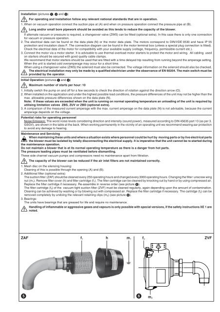
2. Additional filter (optional extra):<br />
The suction filter (ZAF) should be cleaned every 250 operating hours and changed every 3000 operating hours. Changing the filter: unscrew wing<br />
nut (m 1 ). Remove filter cover (h) and filter cartridge (f 1 ). The filter cartridge can be cleaned by knocking out by hand or by using compressed air.<br />
Replace the filter cartridge if necessary. Re-assemble in reverse order (see picture ).<br />
The filter cartridge (f 2 ) of the vacuum tight suction filter (ZVF) must be cleaned regularly, again depending upon the amount of contamination.<br />
Cleaning can be achieved by washing or by blowing out with compressed air. Replace the filter cartridge if necessary. The cartridge (f 2 ) can be<br />
removed completely by undoing the relevant retaining clips (m 2 ) (see picture ).<br />
3. Bearings:<br />
The units have bearings that are greased for life and require no maintenance.<br />
Handling of inflammable or aggressive gases and vapours is only possible with special versions, if the safety instructions XE 1 are<br />
noted.<br />
ZAF<br />
ZVF<br />
<br />
f 1 h m 1 f 2<br />
m 2