Digital Photoelectric Sensor PS-N10 Series Instruction Manual ...
Digital Photoelectric Sensor PS-N10 Series Instruction Manual ...
Digital Photoelectric Sensor PS-N10 Series Instruction Manual ...

Create successful ePaper yourself
Turn your PDF publications into a flip-book with our unique Google optimized e-Paper software.
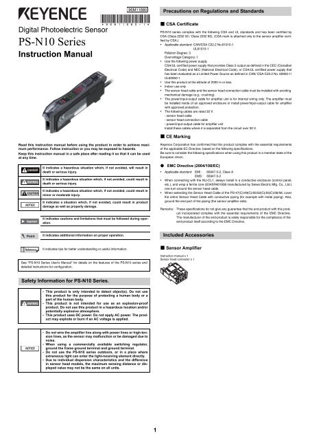
96M11680Precautions on Regulations and Standards<strong>Digital</strong> <strong>Photoelectric</strong> <strong>Sensor</strong><strong>PS</strong>-<strong>N10</strong> <strong>Series</strong><strong>Instruction</strong> <strong>Manual</strong>• CSA Certificate<strong>PS</strong>-<strong>N10</strong> series complies with the following CSA and UL standards and has been certified byCSA (Class 2252 05 / Class 2252 85). (CSA mark is attached only to the sensor amplifier certifiedby CSA.)• Applicable standard: CAN/CSA C22.2 No.61010-1UL61010-1Pollution Degree: 3Overvoltage Category: I• Use the following power supply.CSA/UL certified power supply that provides Class 2 output as defined in the CEC (CanadianElectrical Code) and NEC (National Electrical Code), or CSA/UL certified power supply thathas been evaluated as a Limited Power Source as defined in CAN/ CSA-C22.2 No. 60950-1/UL60950-1• Use this product at the altitude of 2000 m or less.• Indoor use only.• The sensor head cable and the sensor head connection cable must be installed with avoidingmechanical damage (e.g.: crushing).• The power/input-output cable for amplifier unit is for internal wiring only. The amplifier mustbe installed inside of an approved enclosure or install power/input-output cable for amplifierwith approved protection.• The following cables are rated 30 V.- sensor head cable- sensor head connection cable- power/input-output cable for amplifier unitInstall these cables where it is separated from the circuit over 30 V.• CE MarkingRead this instruction manual before using the product in order to achieve maximumperformance. Follow instruction or you may be exposed to hazards.Keep this instruction manual in a safe place after reading it so that it can be usedat any time.Keyence Corporation has confirmed that this product complies with the essential requirementsof the applicable EC Directive, based on the following specifications.Be sure to consider the following specifications when using this product in a member state of theEuropean Union.DANGERWARNINGCAUTIONNOTICEImportantIt indicates a hazardous situation which, if not avoided, will result indeath or serious injury.It indicates a hazardous situation which, if not avoided, could result indeath or serious injury.It indicates a hazardous situation which, if not avoided, could result inminor or moderate injury.It indicates a situation which, if not avoided, could result in productdamage as well as property damage.It indicates cautions and limitations that must be followed during operation.• EMC Directive (2004/108/EC)• Applicable standard EMI : 60947-5-2, Class AEMS : 60947-5-2• When connecting with the NU-CL1, always install in a conductive enclosure (control panel,etc.), and wrap a ferrite core (E04SR401938 manufactured by Seiwa Electric Mfg. Co., Ltd.)one turn around the sensor head cable.• When extending the <strong>Sensor</strong> Head Cable of the <strong>PS</strong>-47(C)/49(C)/05/52(C)/55(C)/56/58, coverthe entire <strong>Sensor</strong> Head Cable with conductive piping (for example with metal piping). Also,ground the end part of the piping (the sensor amplifier side).Remarks:These specifications do not give any guarantee that the end-product with this productincorporated complies with the essential requirements of the EMC Directive.The manufacturer of the end-product is solely responsible for the compliance of theend-product itself according to the EMC Directive.PointIt indicates additional information on proper operation.Included AccessoriesReferenceIt indicates tips for better understanding or useful information.See "<strong>PS</strong>-<strong>N10</strong> <strong>Series</strong> User's <strong>Manual</strong>" for details on the features of the <strong>PS</strong>-<strong>N10</strong> series anddetailed instructions for configuration.• <strong>Sensor</strong> Amplifier<strong>Instruction</strong> manual x 1<strong>Sensor</strong> head connector x 1Safety Information for <strong>PS</strong>-<strong>N10</strong> <strong>Series</strong>.WARNING• This product is only intended to detect object(s). Do not usethis product for the purpose of protecting a human body or apart of the human body.• This product is not intended for use as an explosion-proofproduct. Do not use this product in a hazardous location and/orpotentially explosive atmosphere.• This product uses DC power. Do not apply AC power. The productmay explode or burn if an AC voltage is applied.NOTICE• Do not wire the amplifier line along with power lines or high-tensionlines, as the sensor may malfunction or be damaged due tonoise.• When using a commercially available switching regulator,ground the frame ground terminal and ground terminal.• Do not use the <strong>PS</strong>-<strong>N10</strong> series outdoors, or in a place whereextraneous light can enter the light-receiving element directly.• Due to individual dispersion characteristics and the differencein sensor head models, the maximum sensing distance or displayedvalue may not be the same on all units.1
• <strong>Sensor</strong> Head• <strong>PS</strong>-45Mounting bracket set• <strong>PS</strong>-46ReceiverReceiverTransmitterMounting bracket x 1Plate nut x 1M3 x 12 screw x2TransmitterNut x 2Spring washer x 2Flat washer x 2M2 x 10 screw x 2• <strong>PS</strong>-47/<strong>PS</strong>-47C* 1 Transmitter• <strong>PS</strong>-48Mounting bracket x 1ReceiverReceiverTransmitter• <strong>PS</strong>-49/<strong>PS</strong>-49C* 1 Transmitter• <strong>PS</strong>-05Transmitter (T)Receiver (R)ReceiverNut x 2Spring washer x 2Flat washer x 2M3 x 14 screw x 2For fixing the headHolderSpring washer x 4M3 x 10 screw x 4For fixing the holder• <strong>PS</strong>-52/<strong>PS</strong>-52C* 1 Transmitter (T)• <strong>PS</strong>-55/<strong>PS</strong>-55C* 1 Transmitter (T) Receiver (R)Receiver (R)Nut x 4Spring washer x 4Flat washer x 4M2 x 10 screw x 4• <strong>PS</strong>-56• <strong>PS</strong>-58Transmitter (T)Receiver (R)Transmitter (T) Receiver (R) Mounting bracket x 2Nut x 4Spring washer x 4Flat washer x 4M2 x 10 screw x 4• <strong>PS</strong>-201/<strong>PS</strong>-201C* 1• <strong>PS</strong>-202Transmitter(T) Receiver (R) Mounting bracket x 2Transmitter (T) Receiver (R) Mounting bracket x 2• <strong>PS</strong>-205• <strong>PS</strong>-206ReceiverReceiverTransmitterTransmitter*1 A sensor head connector is attached to the end of the cable for the sensor heads with model names containing the suffix C.2
<strong>PS</strong>-<strong>N10</strong> <strong>Series</strong> Quick StartConnecting the <strong>Sensor</strong> Head to the <strong>Sensor</strong> Amplifier• Quick StartFine sensitivity adjustmentUpDownMode/Output * 2Press the [MODE] button once, thenuse to select L-on or D-on• Installing the <strong>Sensor</strong> Head Connector1 Process the cable ends as shown below. The core wire conductors are stripped sothat they are exposed at the time of shipment. Be sure to process the cables withoutremoving the insulation from the cable ends.Preset functionSetting value Light intensitySensitivity settingPress once each for workpiece/no workpieceSELMPower select switch * 1SELStandard MEGA (fixed)MConfigure easilywith a single presswhen receiving light10 mm or longerShielded wireCablecore2 Move the upper left part of the connector in the direction of the arrow and then openthe connector.*1 Not available for 0-line types.*2 Press and hold the [MODE] button to make advanced setting changes.Names of Each Part of the Main Unit and Expansion UnitHead lock lever3 Fully insert the cables with the shielded wires standing upright. Next, bend theshielded wires along the grooves in the direction of the arrow.SET button (SET)Operation status indicators<strong>PS</strong>T indicatorDTM indicator<strong>Digital</strong> display<strong>Manual</strong> button( )Sub screen(Displayed in green)Main screen(Displayed in red)White wireRed wire4 Close the connector to crimp the cables. Return the upper part of the connector to itsoriginal position and then lock it.Powerselection switchMODE button (MODE)Cable*Dust coverExpansionprotective coverExpansion connectorPreset button (PRESET)Power select switch5 Using nippers, cut off the ends of cables protruding from the connector.* On the <strong>PS</strong>-N11Cx / N12Cx, this is an M8 connector rather than a cable. Not available for 0-linetypes.Mounting Unit• Mounting on a DIN Rail1 Align the claw at the bottom of the main bodywith the DIN rail, as shown on the right.While pushing the main body in the directionof the arrow 1, push down in the direction ofarrow 2.2 To dismount the sensor, raise the main bodyin the direction of the arrow 3 while pushingthe main body in the direction of arrow 1.321NOTICECrimp the cables no more than three times. Excessively crimping thecables may result in a bad connection.• Connecting the <strong>Sensor</strong> Head1 Open the dust cover, and move thehead lock lever down.• Installation on a Wall (Main Unit Only)1 Attach the unit to the optional mountingbracket (OP-73880), and secure with two M3screws as shown on the right.2 Lift the hook up, and insert the connectorcompletely.3 Lower the hook to theposition shown in thedrawing, and securethe head lock lever bypushing up.3
Mounting the <strong>Sensor</strong> Head• <strong>PS</strong>-45• <strong>PS</strong>-201(C)/202Use the supplied fixing bracket or similar bracket. Install the M3 screws.Use the supplied fixing brackets. There are two ways to mount the sensor head. Make sure thetightening torque does not exceed 0.6 Nm.CAUTION• Do not use setscrews to install the bracket.• Do not bend the 20 mm cable that runs from the end of the sensorhead. Maintain a minimum bend radius of 25 mm.• <strong>PS</strong>-46/52(C)/56Use the supplied screws or other similar screws. Make sure the tightening torque does notexceed the following values:<strong>PS</strong>-46/56: 0.3 Nm or less<strong>PS</strong>-52: 0.15 Nm or less• <strong>PS</strong>-205/206Install the M4 screws. Make sure the tightening torque does not exceed 0.5 Nm.CAUTIONDo not bend the 20 mm cable that runs from the end of the sensorhead. Maintain a minimum bend radius of 25 mm.• <strong>PS</strong>-47(C)/49(C)/55(C)Install the M3 screws. Make sure the tightening torque does not exceed 0.6 Nm.• <strong>PS</strong>-48/58Install the M3 screws when using the supplied fixing brackets.Make sure to observe the following requirements when using setscrews to mount the sensorhead:M3 setscrew (flat or dented head)LModel L Tightening torque<strong>PS</strong>-48<strong>PS</strong>-585 mm or longer7 mm or longer0.15 Nm or lessCAUTIONNote If you place the reflective <strong>PS</strong>-48 in the mounting hole, it isaffected by the light reflected from inside the hole. Place the front sideof the <strong>PS</strong>-48 so that it sticks out of the mounting hole, as shown above.• <strong>PS</strong>-05When installing the holder, use the supplied screws and spring washers or other similar parts, asshown on the right. Make sure the tightening torque does not exceed 0.5 Nm.When fixing the <strong>PS</strong>-05 to the holder, use the supplied screw, nuts, spring washer, and flatwasher or other similar parts, as shown on the right. Make sure the tightening torque does notexceed 0.5 Nm.4
Connecting Multiple AmplifiersOther Calibration MethodsUp to 16 expansion units can be connected to one main unit. Note, however, that the 2 outputtype is handled as two expansion units.CAUTIONMount on DIN rail and install on metal surface when connecting to multipleamplifiers or mounting main units together.• Increased Resistance to Dust and Dirt• Maximum Sensitivity CalibrationIn the state shown below, press and hold the [SET] button for three seconds or more. Stop pushingwhen "SET" flashes. The sensitivity is set slightly higher than the received light intensity.Point• Contact your nearest KEYENCE office when connecting units otherthan the N-bus (name of KEYENCE’s wire-saving system) compatiblesensor amplifier, including <strong>PS</strong>-<strong>N10</strong> <strong>Series</strong>, or the NU <strong>Series</strong> communicationmodule.• Turn the power off before connecting multiple expansion units.• Do not touch the expansion connector with your bare hands.• When using the <strong>PS</strong>-<strong>N10</strong> series as a main unit, verify that expansionproducts used (other than <strong>PS</strong>-<strong>N10</strong> series expansion units) can operatewithin the power voltage range of the <strong>PS</strong>-<strong>N10</strong> series.Thru-Beam Model : with workpiece Reflective Model : without workpiece1 Remove the protection covers from the main unitand expansion unit(s).2 Install the amplifiers on the DIN rail, one at a time.• Calibrate with a Moving Workpiece• Full Auto CalibrationPress and hold the [SET] button with no workpiece in place. While "SET" is flashing, pass aworkpiece through. (Continue pressing the [SET] button while the workpiece passesthrough.)Common toThru-Beam Model and Reflective Model23 Slide the main unit and expansion unit(s) together.Engage the two claws of the expansion unit withthe recesses on the main unit side until you hear/feel a click.4 Attach the end units (option: OP-26751) to the DINrail in the same way as step (2).5 Secure the amplifiers between the end units.Tighten the screws at the top (two screws per unit)with a Phillips screwdriver to fix the end units.Calibration Method1OP-26751 (a set of two)• Workpiece Positioning• Positioning CalibrationPress the [SET] button with no workpiece.Place the workpiece in the location you wish to position it. Press and hold the [SET] buttonfor at least 3 seconds. Release the button when "SET" flashes.Common toThru-Beam Modeland Reflective Model• To Detect Small Differences• Two-point CalibrationTwo-point calibration is the basic method of calibration.Press the [SET] button once without the workpiece, and then press it once again with theworkpiece.Common toThru-Beam Model and Reflective ModelWorkpiece1 Press the [SET] button with no workpiece.[SET] will be displayed on the sub-menu (green display).SELM2 Press the [SET] button with a workpiece.When complete, the values will be set and the submenu (green display) will flash. The setpoint will be calibrated to the mid-point between the light intensity when there is no workpiece,and the light intensity when there is a workpiece.SELMWorkpieceIf "----" flashes for two seconds on the main screen, the light intensity is too small betweenconditions when the workpiece is absent and when it is present. These values will be set,but there is the possibility that detection may become unstable.5
• Disable the Zero Shift FunctionPress and hold the [PRESET] button to disable the zero shift function.ReferenceOutput SwitchEither light-ON (L-on) mode or dark-ON (D-on) mode can be selected.1 While the current value is displayed,press the [MODE] button once.2 Use to switch the output (L-on/D-on), then press the [MODE] button again.The output change completes, and the display returns to the current value.Initializing the Settings• Initialization Method1 Press and hold the [SET] and[PRESET] buttons simultaneouslyfor more than three seconds.The light intensity may not be set to ".0" when the reflective model sensorhead is first installed.In this case, using the zero shift function to set the state with no targetpresent to ".0" will make it easier to see the difference in light intensities.SELMError Displays and Corrective ActionsError display Cause SolutionErCErHErELocThe DTM indicatorflashes.Overcurrent in the control output.<strong>Sensor</strong> head cable is broken oris not connected.Internal data write / load failed.Key lock function is enabled, orthe power mode was fixed toMEGA mode using the selectorswitch.Correction error in DATUM1 orDATUM 2 mode.For errors other than the above, contact your nearest KEYENCE office.Connecting to External Devices• Check the load and return the currentwithin the rated range.• Check that the output wire is notcontacting any other wire or frame.• Check that the sensor head isconnected.• Check sensor head cable for damage.• Check the sensor head cable connectorfor damage or loose connections.After checking, turn the powerOFF and ON.Turn the power OFF and ON. If thedata is not recovered, initialize thesettings.• Release the key lock.• Check that the sensor amplifierselector switch is set to MEGAmode.See "<strong>PS</strong>-<strong>N10</strong> <strong>Series</strong> UserÊs <strong>Manual</strong>"for details.Press and hold for 3 seconds or moreSELM• Cable Type<strong>PS</strong>-N11N / N12NInput / output circuit diagram<strong>PS</strong>-N11P / N12PInput / output circuit diagram2 Use the to select "RST", then press the [MODE] button.3 Use the to select "iNiT", then press the [MODE] button.After initialization is complete, the display returns to the current value.• Initial SettingsSettingInitial value<strong>Sensor</strong> main circuitOvercurrent protection circuit3.3 VDCBrown* 1Black(Control output)PinkBlue* 1Load10-30 VDCShort-circuit currentPLC, etc. 1 mA or less0V<strong>Sensor</strong> main circuitOvercurrent protection circuitBrown* 1Black(Control output)PinkBlue* 1Load10-30 VDCPLC, etc.Short-circuit current2 mA or less0VPower mode TURBODetection mode Std (Normal)Setting value 50Output switch L-on*1 <strong>PS</strong>-N11N only *1 <strong>PS</strong>-N11P only• M8 Connector Type<strong>PS</strong>-N11CN / N12CN<strong>PS</strong>-N11CP / N12CPInput / output circuit diagramInput / output circuit diagramKey LockThe key lock function disables button operation to prevent unauthorized use.• Activating Key Lock1 Press and hold the [MODE] buttonand (or ) simultaneously forthree seconds or more.2 The screen displays "Loc", disablingkey operation.• Deactivating Key Lock1 Press and hold the [MODE] buttonand (or ) simultaneously forthree seconds or more.2 The screen displays "unL", enablingkey operation.SELSELMM<strong>Sensor</strong> main circuitOvercurrent protection circuit3.3 VDC *1*1 <strong>PS</strong>-N11CN only *1 <strong>PS</strong>-N11CP only• Socket Cable (Sold Separately)For <strong>PS</strong>-N11Cx / N12Cx(Control output) *1Load10-30 VDCShort-circuit currentPLC, etc. 1 mA or less0V<strong>Sensor</strong> main circuitOvercurrent protection circuit (Control output )2 42M8 connector pin layout1 3M8 connector pin layout1OP-73864(Cable length: 2 m)OP-73865(Cable length: 10 m)4321 Load10-30 VDCPLC, etc.Short-circuit current2 mA or lessPin and wire color tableConnectedpin No. Wire color1 Brown234WhiteBlueBlack0V437
Function Configuration• Display Settings (diSP)See "<strong>PS</strong>-<strong>N10</strong> <strong>Series</strong> User's <strong>Manual</strong>" for details on each function.• Basic SettingMODEPress and hold for 3 seconds or moreTURBO modeSUPER modeULTRA modeMEGA modeNormal sensitivity setting methodPercentage Calibration* 1Normal display methodReverse displaySub-display offExtension displayBar displayExcess gain (%) displayLight intensity hold display * 1Excess gain hold (%) display * 1L-on / D-on displayReturn to normal displayZero-shift calibrationSettings completeGo to detection setup modeGo to display setup modeGo to system setup modeEnable the saturation of thePreset function * 2Disable the saturation of thePreset functionSettings completeGo to system setup modeGo to detection setup modeReturn to display setup modeMODE*1 You can press the button to set between the range of -99P and 99P.• Detection Settings (Func)MODE*1 Press the button to toggle between Std/P~P_/b~b_/P_b~/P~b_.MODEReturn to normal display*2 Press the button to set between the range of 100P and 200P.Timer OFFOff-delay timer * 1On-delay timer * 1One-shot timer * 1Normal (light intensity)detection modeDATUM1 mode * 2DATUM2 mode * 2Area detection modeRising Edge Detection ModeFalling Edge Detection Mode*4External input offExternal calibration inputPreset inputZero shift inputReset inputLight transmission OFF inputPause mode transition input * 3Sleep mode transition inputMODESettings completeReturn to normal displayMODEGo to display setup modeGo to system setup modeReturn to detectionsetup mode*1 Press the button to set between the range of 1 and 9999(ms).MODE*2 Press the button to set the adjustment sensitivity to a range of between LEu1 andLEu3 and set the warning output level to a range of between OP and 100P.MODE*3 Press the button to toggle between oFF/oN/KEEP.*4 This display does not appear on the cable-type expansion unit (<strong>PS</strong>-N12N/N12P).8
• System Settings (SYS)Eco feature offEnable eco featureReduce power consumption(response time 4 times slower)Standard current value displayMaximum current value display(4 times hysteresis)Normal operationTwice the number ofinterference-prevention units as STD(response time 2 times slower)*1Disable common key operationsEnable common key operations*2Disable long modeEnable long modeSettings completeGo to detection setup modeGo to display setup modeReturn to system setup modeReturn to normal display*1 Main unit only.*2 The <strong>PS</strong>-47(C), <strong>PS</strong>-48, <strong>PS</strong>-49(C), <strong>PS</strong>-58 and <strong>PS</strong>-206 do not support long-distance detectionmode. Do not select long-distance detection mode when using these sensor heads.ReferenceMODE• Press the button and the button simultaneously to return to theprevious setting.MODE• When the button is held down, the settings will end.9
Specifications• Transparent <strong>Sensor</strong> HeadsThru-beam typeTypeGeneral-purposeEnvironmentally resistant typeLong distance Adjustable axis Cylinder Flat Long distance Built-in grooveModel *1 <strong>PS</strong>-55(C) <strong>PS</strong>-05 <strong>PS</strong>-58 <strong>PS</strong>-52(C) <strong>PS</strong>-56 <strong>PS</strong>-201(C) <strong>PS</strong>-202MEGA 3600 (6000) 3600 (6000) 1000 1200 (1500) 750 (900) 3600 (6000) 900 (1000)DetectionULTRA 2800 (5000) 2800 (5000) 900 800 (1000) 500 (600) 2800 (5000) 700 (900)distance *2(mm)SUPER 2200 (4200) 2200 (4200) 750 400 (650) 400 (450) 2200 (4200) 600 (800)TURBO 2000 (4000) 2000 (4000) 700 300 (600) 300 (400) 2000 (4000) 500 (750)Smallest detectableobject *3 Ф 1 mm opaque Ф 0.5 mm opaque Ф 0.3 mm opaque Ф 0.3 mm opaque Ф 0.8 mm opaque Ф 0.5 mm opaqueEnvironmentalresistanceLight sourceLED ClassProtectionstructureOperatingambienttemperatureOperatingambientluminanceVibrationresistanceWeight(2 m cable included)Infrared LEDClass 1 LED Product (IEC60825-1)IP64 IP67 - IP67-10ºC to +60ºC (no freezing)Incandescent lamp: 4,000 lx or less; sunlight: 12,000 lx or less10 to 55 Hz, compound amplitude 1.5 mm, 2 hours for each axis (X, Y, and Z)Approx. 30 g Approx. 30 g Approx. 30 g Approx. 30 g Approx. 30 g Approx. 40 g Approx. 40 g*1 A sensor head connector is attached to the end of the cable for the sensor heads with model names containing the suffix C.*2 The values in parentheses indicate the detection distance when long-distance detection mode is enabled and a 5 m sensor head cable is used.*3 The size of a workpiece that can be detected at the maximum detection distance.• Reflective <strong>Sensor</strong> HeadsDiffuse reflective typeLimited reflective typeTypeGeneral-purpose Environmentally resistant General-purposeLong distance Flat Cylinder Long distance Narrow vision Small spot Long distanceModel *1 <strong>PS</strong>-45 <strong>PS</strong>-46 <strong>PS</strong>-48 <strong>PS</strong>-205 <strong>PS</strong>-206 <strong>PS</strong>-47(C) <strong>PS</strong>-49(C)MEGA 600 (900) 200 (250) 75 600 (900) 250DetectionULTRA 400 (600) 150 (200) 45 400 (600) 180distance *2(mm)SUPER 250 (450) 120 (160) 30 250 (450) 10010μ4 32 to 53TURBO 200 (400) 100 (140) 25 200 (400) 70Smallest detectableobject *3 φ- - φ- - -EnvironmentalresistanceSpot diameter - - - -Ф 6 mmwhen the detectiondistance is 70 mmФ 0.03 mm copperwireФ 8 mmwhen the detectiondistance is 10 mmLight source Infrared LED Red LEDLED ClassClass 1 LED Product (IEC60825-1)ProtectionstructureIP64 - IP67 -OperatingambienttemperatureOperatingambientluminanceVibrationresistanceWeight(2 m cable included)-10ºC to +60ºC (no freezing)Incandescent lamp: 4,000 lx or less; sunlight: 12,000 lx or less10 to 55 Hz, compound amplitude 1.5 mm, 2 hours for each axis (X, Y, and Z)Ф 0.1 mm copperwireФ 1.5 mmwhen the detectiondistance is 50 mm-10ºC to +50ºC(no freezing)Incandescent lamp: 4,000 lx or less; sunlight:5,000 lx or lessApprox. 30 g Approx. 30 g Approx. 40 g Approx. 60 g Approx. 60 g Approx. 30 g Approx. 30 g*1 There is a sensor head connector attached to the end of the cable for the sensor heads with model names containing the suffix C.*2 The values in parentheses indicate the detection distance when long-distance detection mode is enabled.*3 The values obtained by optimizing the detection distance and sensitivity.10
• <strong>Sensor</strong> AmplifierCable / Connector Cable M8 Connector 0-lineMain unit / Expansion unit Main unit Expansion unit Main unit Expansion unit Expansion unitModelControl outputNPN <strong>PS</strong>-N11N <strong>PS</strong>-N12N <strong>PS</strong>-N11CN <strong>PS</strong>-N12CNPNP <strong>PS</strong>-N11P <strong>PS</strong>-N12P <strong>PS</strong>-N11CP <strong>PS</strong>-N12CPControl output 1 output 1 output 1 output 1 output N/A *1External input 1 input N/A 1 input 1 input N/AResponse timeOutput operationTimer functionNPN outputPNP output500 μs (TURBO)/1 ms (SUPER)/4 ms (ULTRA)/16 ms (MEGA)Light-ON/Dark-ONTimer OFF, OFF delay, ON delay, One-shotTimer variable (1 ms to 9999 ms) Maximum error to setting value is μ10 % or less*1 Counted as one output when units are added to NU series communication units.*2 Input time is 25 ms (ON)/25 ms (OFF) only when an external tuning input is selected.*3 The operating ambient temperature varies as shown below when units are added. For expansion, be sure to mount the units on the DIN rail (metallic plate) andprevent the output current for each unit from exceeding 20 mA.- 20ºC to + 55ºC for 1 or 2 units added, - 20ºC to + 50ºC for 3 to 10 units added, - 20ºC to + 45ºC for 11 to 16 units added*4 When connecting nine or more expansion units, ensure that the power voltage is 20 V or more.*5 The maximum power consumption including load is 29.3 W.*6 Use with the over current protection device which is rated 30 V or more and not more than 1 A.<strong>PS</strong>-<strong>N10</strong>NPN open collector 30 V, Max: 100 mA or less (for standalone operation)/20 mA or less (for expansion)Residual voltage 1 V or less (Output current: 10 mA or less)/2 V or less (Output current: 10 to 100 mA)PNP open collector 30 V, Max: 100 mA or less (standalone operation)/20 mA or less (for expansion)Residual voltage 1.2 V or less (Output current: 10 mA or less)/2.2 V or less (Output current: 10 to 100 mA)External input No-voltage input (with/without contact), Input time 2 ms (ON)/20 ms (OFF) or more *2Expansion unitsProtection circuitNumber of interference prevention unitsRatedEnvironmentalresistanceMaterialHousing dimensionsPower voltage *4Up to 16 units (a total of 17 units connected)Protection against reverse power connection, output overcurrent, output surge, and output wiring errorTURBO/SUPER/ULTRA/MEGA: 4 (These numbers double when "Double" is selected.)24 VDC (operating voltage 10-30 VDC (including ripple)), ripple (P-P) 10 % or less, Class 2 or L<strong>PS</strong>Normal: 810 mW or less (28 mA or less at 24 and 30 V, 34 mA or less at 12 V)NPN *5 Eco on: 700 mW or less (24 mA or less at 24 and 30 V, 27 mA or less at 12 V)Eco full: 490 mW or less (17 mA or less at 24 and 30 V, 20 mA or less at 12 V)Normal: 860 mW or less (30 mA or less at 24 and 30 V, 35 mA or less at 12 V)PNP *5 Eco on: 750 mW or less (26 mA or less at 24 and 30 V, 28 mA or less at 12 V)Eco full: 540 mW or less (19 mA or less at 24 and 30 V, 21 mA or less at 12 V)Operating ambient- 20°ºC to + 55°ºC (no freezing)temperature*3Operating ambienthumidityVibration resistanceShock resistanceHousingCable35 to 85 % RH (no condensation)10 to 55 Hz, compound amplitude 1.5 mm, 2 hours for each of X, Y, Z axes500 m/s 2 , 3 times for each of X, Y, Z axesAmplifier body and dust cover material: PolycarbonatePVCH 32.6 mm x W 9.8 mm x L 78.7 mmWeight Approx. 75 g Approx. 65 g Approx. 20 g Approx. 20 g Approx. 20 g11
WARRANTIES AND DISCLAIMERS(1) KEYENCE warrants the Products to be free of defects in materials andworkmanship for a period of one (1) year from the date of shipment. If anymodels or samples were shown to Buyer, such models or samples were usedmerely to illustrate the general type and quality of the Products and not torepresent that the Products would necessarily conform to said models orsamples. Any Products found to be defective must be shipped to KEYENCEwith all shipping costs paid by Buyer or offered to KEYENCE for inspection andexamination. Upon examination by KEYENCE, KEYENCE, at its sole option, willrefund the purchase price of, or repair or replace at no charge any Productsfound to be defective. This warranty does not apply to any defects resultingfrom any action of Buyer, including but not limited to improper installation,improper interfacing, improper repair, unauthorized modification,misapplication and mishandling, such as exposure to excessive current, heat,coldness, moisture, vibration or outdoors air. Components which wear are notwarranted.(2) KEYENCE is pleased to offer suggestions on the use of its various Products.They are only suggestions, and it is Buyer's responsibility to ascertain thefitness of the Products for Buyer's intended use. KEYENCE will not beresponsible for any damages that may result from the use of the Products.(3) The Products and any samples ("Products/Samples") supplied to Buyer are notto be used internally in humans, for human transportation, as safety devices orfail-safe systems, unless their written specifications state otherwise. Shouldany Products/Samples be used in such a manner or misused in any way,KEYENCE assumes no responsibility, and additionally Buyer will indemnifyKEYENCE and hold KEYENCE harmless from any liability or damagewhatsoever arising out of any misuse of the Products/Samples.(4) OTHER THAN AS STATED HEREIN, THE PRODUCTS/SAMPLES AREPROVIDED WITH NO OTHER WARRANTIES WHATSOEVER. ALLEXPRESS, IMPLIED, AND STATUTORY WARRANTIES, INCLUDING,WITHOUT LIMITATION, THE WARRANTIES OF MERCHANTABILITY,FITNESS FOR A PARTICULAR PURPOSE, AND NON-INFRINGEMENT OFPROPRIETARY RIGHTS, ARE EXPRESSLY DISCLAIMED.IN NO EVENT SHALL KEYENCE AND ITS A FFILIATED ENTITIES BELIABLE TO ANY PERSON OR ENTITY FOR ANY DIRECT, INDIRECT,INCIDENTAL, PUNITIVE, SPECIAL OR CONSEQUENTIAL DAMAGES(INCLUDING, WITHOUT LIMITATION, ANY DAMAGES RESULTING FROMLOSS OF USE, BUSINESS INTERRUPTION, LOSS OF INFORMATION,LOSS OR INACCURACY OF DATA, LOSS OF PROFITS, LOSS OFSAVINGS, THE COST OF PROCUREMENT OF SUBSTITUTED GOODS,SERVICES OR TECHNOLOGIES, OR FOR ANY MATTER ARISING OUT OFOR IN CONNECTION WITH THE USE OR INABILITY TO USE THEPRODUCTS, EVEN IF KEYENCE OR ONE OF ITS AFFILIATED ENTITIESWAS ADVISED OF A POSSIBLE THIRD PARTYÊS CLAIM FOR DAMAGESOR ANY OTHER CLAIM AGAINST BUYER. In some jurisdictions, some of theforegoing warranty disclaimers or damage limitations may not apply.BUYER'S TRANSFER OBLIGATIONS:If the Products/Samples purchased by Buyer are to be resold or delivered to athird party, Buyer must provide such third party with a copy of this document,all specifications, manuals, catalogs, leaflets and written information providedto Buyer pertaining to the Products/Samples.E 1110-2www.keyence.comCopyright (c) 2011 KEYENCE CORPORATION. All rights reserved.11679E 1041-1 96M11680 Printed in Japan12