Digital Photoelectric Sensor PS-N10 Series Instruction Manual ...
Digital Photoelectric Sensor PS-N10 Series Instruction Manual ...
Digital Photoelectric Sensor PS-N10 Series Instruction Manual ...

You also want an ePaper? Increase the reach of your titles
YUMPU automatically turns print PDFs into web optimized ePapers that Google loves.
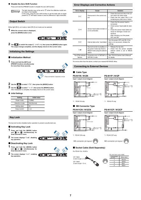
• Disable the Zero Shift FunctionPress and hold the [PRESET] button to disable the zero shift function.ReferenceOutput SwitchEither light-ON (L-on) mode or dark-ON (D-on) mode can be selected.1 While the current value is displayed,press the [MODE] button once.2 Use to switch the output (L-on/D-on), then press the [MODE] button again.The output change completes, and the display returns to the current value.Initializing the Settings• Initialization Method1 Press and hold the [SET] and[PRESET] buttons simultaneouslyfor more than three seconds.The light intensity may not be set to ".0" when the reflective model sensorhead is first installed.In this case, using the zero shift function to set the state with no targetpresent to ".0" will make it easier to see the difference in light intensities.SELMError Displays and Corrective ActionsError display Cause SolutionErCErHErELocThe DTM indicatorflashes.Overcurrent in the control output.<strong>Sensor</strong> head cable is broken oris not connected.Internal data write / load failed.Key lock function is enabled, orthe power mode was fixed toMEGA mode using the selectorswitch.Correction error in DATUM1 orDATUM 2 mode.For errors other than the above, contact your nearest KEYENCE office.Connecting to External Devices• Check the load and return the currentwithin the rated range.• Check that the output wire is notcontacting any other wire or frame.• Check that the sensor head isconnected.• Check sensor head cable for damage.• Check the sensor head cable connectorfor damage or loose connections.After checking, turn the powerOFF and ON.Turn the power OFF and ON. If thedata is not recovered, initialize thesettings.• Release the key lock.• Check that the sensor amplifierselector switch is set to MEGAmode.See "<strong>PS</strong>-<strong>N10</strong> <strong>Series</strong> UserÊs <strong>Manual</strong>"for details.Press and hold for 3 seconds or moreSELM• Cable Type<strong>PS</strong>-N11N / N12NInput / output circuit diagram<strong>PS</strong>-N11P / N12PInput / output circuit diagram2 Use the to select "RST", then press the [MODE] button.3 Use the to select "iNiT", then press the [MODE] button.After initialization is complete, the display returns to the current value.• Initial SettingsSettingInitial value<strong>Sensor</strong> main circuitOvercurrent protection circuit3.3 VDCBrown* 1Black(Control output)PinkBlue* 1Load10-30 VDCShort-circuit currentPLC, etc. 1 mA or less0V<strong>Sensor</strong> main circuitOvercurrent protection circuitBrown* 1Black(Control output)PinkBlue* 1Load10-30 VDCPLC, etc.Short-circuit current2 mA or less0VPower mode TURBODetection mode Std (Normal)Setting value 50Output switch L-on*1 <strong>PS</strong>-N11N only *1 <strong>PS</strong>-N11P only• M8 Connector Type<strong>PS</strong>-N11CN / N12CN<strong>PS</strong>-N11CP / N12CPInput / output circuit diagramInput / output circuit diagramKey LockThe key lock function disables button operation to prevent unauthorized use.• Activating Key Lock1 Press and hold the [MODE] buttonand (or ) simultaneously forthree seconds or more.2 The screen displays "Loc", disablingkey operation.• Deactivating Key Lock1 Press and hold the [MODE] buttonand (or ) simultaneously forthree seconds or more.2 The screen displays "unL", enablingkey operation.SELSELMM<strong>Sensor</strong> main circuitOvercurrent protection circuit3.3 VDC *1*1 <strong>PS</strong>-N11CN only *1 <strong>PS</strong>-N11CP only• Socket Cable (Sold Separately)For <strong>PS</strong>-N11Cx / N12Cx(Control output) *1Load10-30 VDCShort-circuit currentPLC, etc. 1 mA or less0V<strong>Sensor</strong> main circuitOvercurrent protection circuit (Control output )2 42M8 connector pin layout1 3M8 connector pin layout1OP-73864(Cable length: 2 m)OP-73865(Cable length: 10 m)4321 Load10-30 VDCPLC, etc.Short-circuit current2 mA or lessPin and wire color tableConnectedpin No. Wire color1 Brown234WhiteBlueBlack0V437