Digital Photoelectric Sensor PS-N10 Series Instruction Manual ...
Digital Photoelectric Sensor PS-N10 Series Instruction Manual ...
Digital Photoelectric Sensor PS-N10 Series Instruction Manual ...

You also want an ePaper? Increase the reach of your titles
YUMPU automatically turns print PDFs into web optimized ePapers that Google loves.
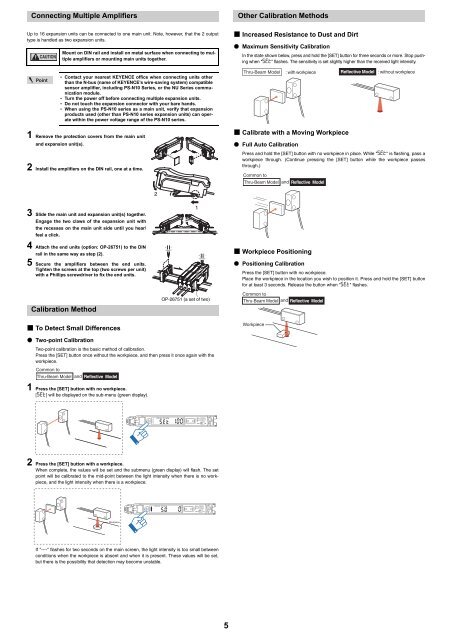
Connecting Multiple AmplifiersOther Calibration MethodsUp to 16 expansion units can be connected to one main unit. Note, however, that the 2 outputtype is handled as two expansion units.CAUTIONMount on DIN rail and install on metal surface when connecting to multipleamplifiers or mounting main units together.• Increased Resistance to Dust and Dirt• Maximum Sensitivity CalibrationIn the state shown below, press and hold the [SET] button for three seconds or more. Stop pushingwhen "SET" flashes. The sensitivity is set slightly higher than the received light intensity.Point• Contact your nearest KEYENCE office when connecting units otherthan the N-bus (name of KEYENCE’s wire-saving system) compatiblesensor amplifier, including <strong>PS</strong>-<strong>N10</strong> <strong>Series</strong>, or the NU <strong>Series</strong> communicationmodule.• Turn the power off before connecting multiple expansion units.• Do not touch the expansion connector with your bare hands.• When using the <strong>PS</strong>-<strong>N10</strong> series as a main unit, verify that expansionproducts used (other than <strong>PS</strong>-<strong>N10</strong> series expansion units) can operatewithin the power voltage range of the <strong>PS</strong>-<strong>N10</strong> series.Thru-Beam Model : with workpiece Reflective Model : without workpiece1 Remove the protection covers from the main unitand expansion unit(s).2 Install the amplifiers on the DIN rail, one at a time.• Calibrate with a Moving Workpiece• Full Auto CalibrationPress and hold the [SET] button with no workpiece in place. While "SET" is flashing, pass aworkpiece through. (Continue pressing the [SET] button while the workpiece passesthrough.)Common toThru-Beam Model and Reflective Model23 Slide the main unit and expansion unit(s) together.Engage the two claws of the expansion unit withthe recesses on the main unit side until you hear/feel a click.4 Attach the end units (option: OP-26751) to the DINrail in the same way as step (2).5 Secure the amplifiers between the end units.Tighten the screws at the top (two screws per unit)with a Phillips screwdriver to fix the end units.Calibration Method1OP-26751 (a set of two)• Workpiece Positioning• Positioning CalibrationPress the [SET] button with no workpiece.Place the workpiece in the location you wish to position it. Press and hold the [SET] buttonfor at least 3 seconds. Release the button when "SET" flashes.Common toThru-Beam Modeland Reflective Model• To Detect Small Differences• Two-point CalibrationTwo-point calibration is the basic method of calibration.Press the [SET] button once without the workpiece, and then press it once again with theworkpiece.Common toThru-Beam Model and Reflective ModelWorkpiece1 Press the [SET] button with no workpiece.[SET] will be displayed on the sub-menu (green display).SELM2 Press the [SET] button with a workpiece.When complete, the values will be set and the submenu (green display) will flash. The setpoint will be calibrated to the mid-point between the light intensity when there is no workpiece,and the light intensity when there is a workpiece.SELMWorkpieceIf "----" flashes for two seconds on the main screen, the light intensity is too small betweenconditions when the workpiece is absent and when it is present. These values will be set,but there is the possibility that detection may become unstable.5