de VOGEL-Spiralgehäusepumpen Baureihe LM, LMN fr VOGEL ...
de VOGEL-Spiralgehäusepumpen Baureihe LM, LMN fr VOGEL ...
de VOGEL-Spiralgehäusepumpen Baureihe LM, LMN fr VOGEL ...

Create successful ePaper yourself
Turn your PDF publications into a flip-book with our unique Google optimized e-Paper software.
<strong>de</strong> <strong>VOGEL</strong>-<strong>Spiralgehäusepumpen</strong><br />
<strong>Baureihe</strong> <strong>LM</strong>, <strong>LM</strong>N<br />
Einbau-, Betriebs- und Wartungsanleitung<br />
Originalbetriebsanleitung<br />
<strong>fr</strong><br />
en<br />
<strong>VOGEL</strong>-Pompes à volute<br />
Série <strong>LM</strong>, <strong>LM</strong>N<br />
<strong>VOGEL</strong>-Volute casing pumps<br />
Mo<strong>de</strong>l <strong>LM</strong>, <strong>LM</strong>N<br />
Instructions <strong>de</strong> montage, <strong>de</strong> service et <strong>de</strong> maintenance<br />
Traduction <strong>de</strong> la notice d’exploitation originale<br />
Installation, Operation and Maintenance Instructions<br />
Translation of the Original Operation Manual<br />
<strong>de</strong><br />
<strong>fr</strong><br />
en<br />
Für künftige Verwendung aufbewahren !<br />
Diese Betriebsanleitung vor <strong>de</strong>m Transport, <strong>de</strong>m Einbau, <strong>de</strong>r Inbetriebnahme usw. genau beachten!<br />
Conserver soigneusement ces instructions pour consultations ultérieures !<br />
Lire attentivement ces instructions <strong>de</strong> service avant le transport, le montage, la mise en service etc. !<br />
Keep for further use !<br />
Pay attention to this operating instruction before the <strong>de</strong>livery, installation, start-up a.s.o.!<br />
Artikel Nr. 771073101 Rev. 06 08/2013
EG-Konformitätserklärung (nur gültig für komplette von Xylem Service Austria GmbH gelieferte Aggregate,<br />
gemäß EG-Maschinenrichtlinie 2006/42/EG Anhang II A)<br />
Hiermit erklärt <strong>de</strong>r Hersteller:<br />
Xylem Service Austria GmbH<br />
Ernst Vogel-Strasse 2<br />
2000 Stockerau<br />
Österreich<br />
<strong>de</strong>r Pumpenaggregate <strong>de</strong>r <strong>Baureihe</strong><br />
<strong>LM</strong> 65-315, <strong>LM</strong> 80-315, <strong>LM</strong> 100-160, <strong>LM</strong> 100-200, <strong>LM</strong> 100-250, <strong>LM</strong> 100-315, <strong>LM</strong> 125-250, <strong>LM</strong><br />
125-200, <strong>LM</strong> 125-315, <strong>LM</strong> 150-250, <strong>LM</strong> 150-315<br />
<strong>LM</strong>N 32-125, <strong>LM</strong>N 32-160, <strong>LM</strong>N 32-200, <strong>LM</strong>N 40-125, <strong>LM</strong>N 40-160, <strong>LM</strong>N 40-200, <strong>LM</strong>N 40-250,<br />
<strong>LM</strong>N 50-125, <strong>LM</strong>N 50-160, <strong>LM</strong>N 50-200, <strong>LM</strong>N 50-250, <strong>LM</strong>N 65-125, <strong>LM</strong>N 65-160, <strong>LM</strong>N 65-200,<br />
<strong>LM</strong>N 80-160, <strong>LM</strong>N 65-160, <strong>LM</strong>N 65-250, <strong>LM</strong>N 80-200, <strong>LM</strong>N 80-250, <strong>LM</strong>N 80-250<br />
dass oben genannte Aggregate allen Bestimmungen <strong>de</strong>r folgen<strong>de</strong>n Richtlinien in ihrer jeweils gültigen<br />
Fassung entsprechen:<br />
EG-Richtlinie 2006/42/EG ”Maschinen”<br />
EG-Richtlinie 2009/125/EG ”EcoDesign” und<br />
begleiten<strong>de</strong> Verordnung (EU) Nr. 547/2012<br />
EG-Richtlinie 2004/108/EG ”EMV”<br />
Die technischen Unterlagen wur<strong>de</strong>n nach Richtlinie 2006/42/EG, Anhang VII A, erstellt.<br />
Die vorgenannten technischen Unterlagen wer<strong>de</strong>n auf Anfor<strong>de</strong>rung <strong>de</strong>r zuständigen Behör<strong>de</strong> in<br />
elektronischer Form auf Datenträgern übermittelt.<br />
Verantwortlicher für die Zusammenstellung <strong>de</strong>r technischen Unterlagen:<br />
Dipl.Ing. Gerhard Fasching<br />
Abtlg. Research & Development<br />
Xylem Service Austria GmbH<br />
Ernst Vogel-Strasse 2<br />
2000 Stockerau<br />
Österreich<br />
Angewen<strong>de</strong>te harmonisierte Normen, insbeson<strong>de</strong>re<br />
EN 809 :1998+A1:2009+AC:2010(D)<br />
EN 953 :1997+A1:2009(D)<br />
EN ISO 12100 :2010(D)<br />
EN 60204-1 :2006/A1:2009 D<br />
Bei einer nicht mit uns abgestimmten Verän<strong>de</strong>rung <strong>de</strong>s Aggregates verliert diese Erklärung ihre Gültigkeit,<br />
ebenso wenn das Aggregat in Anlagen eingebaut wird, bei <strong>de</strong>nen keine Konformitätserklärung<br />
entsprechend <strong>de</strong>r Maschinenrichtlinie 2006/42/EG vorliegt.<br />
Stockerau, 05.07.2013 ................................................................................................<br />
Dipl.Ing. Gerhard Fasching<br />
Manager Research & Development
Déclaration CE <strong>de</strong> conformité (valable uniquement pour les agrégats complets, fournis par la société<br />
Xylem Service Austria GmbH, en vertu <strong>de</strong> la Directive 2006/42/CE relatives aux machines, annexe II A)<br />
Par la présente,<br />
Xylem Service Austria GmbH<br />
Ernst Vogel-Strasse 2<br />
2000 Stockerau<br />
Autriche<br />
Les groupes motopompe <strong>de</strong> la série<br />
<strong>LM</strong> 65-315, <strong>LM</strong> 80-315, <strong>LM</strong> 100-160, <strong>LM</strong> 100-200, <strong>LM</strong> 100-250, <strong>LM</strong> 100-315, <strong>LM</strong> 125-250, <strong>LM</strong><br />
125-200, <strong>LM</strong> 125-315, <strong>LM</strong> 150-250, <strong>LM</strong> 150-315<br />
<strong>LM</strong>N 32-125, <strong>LM</strong>N 32-160, <strong>LM</strong>N 32-200, <strong>LM</strong>N 40-125, <strong>LM</strong>N 40-160, <strong>LM</strong>N 40-200, <strong>LM</strong>N 40-250,<br />
<strong>LM</strong>N 50-125, <strong>LM</strong>N 50-160, <strong>LM</strong>N 50-200, <strong>LM</strong>N 50-250, <strong>LM</strong>N 65-125, <strong>LM</strong>N 65-160, <strong>LM</strong>N 65-200,<br />
<strong>LM</strong>N 80-160, <strong>LM</strong>N 65-160, <strong>LM</strong>N 65-250, <strong>LM</strong>N 80-200, <strong>LM</strong>N 80-250, <strong>LM</strong>N 80-250<br />
Que les groupes motopompe mentionnés ci-<strong>de</strong>ssus sont conformes à l’ensemble <strong>de</strong>s dispositions <strong>de</strong>s<br />
directives suivantes dans leurs versions respectives en vigueur:<br />
EC-Directive 2006/42/EC ”Machinery”<br />
EC-Directive 2009/125/EC ”Eco<strong>de</strong>sign” and<br />
Commission Regulation (EC) No. 547/2012<br />
EC-Directive 2004/108/EC ”EMC”<br />
La documentation technique a été établie conformément à la directive 2006/42/CE, annexe VII A.<br />
Sur <strong>de</strong>man<strong>de</strong>, la documentation technique citée ci-<strong>de</strong>ssus sera transmise sous forme <strong>de</strong> fichier sur support<br />
électronique à l’autorité compétente.<br />
Le responsable pour l’établissement du dossier technique:<br />
Dipl.Ing. Gerhard Fasching<br />
Abtlg. Research & Development<br />
Xylem Service Austria GmbH<br />
Ernst Vogel-Strasse 2<br />
2000 Stockerau<br />
Austria<br />
Normes harmonisées appliquées – principalement :<br />
EN 809 :1998+A1:2009+AC:2010(D)<br />
EN 953 :1997+A1:2009(D)<br />
EN ISO 12100 :2010(D)<br />
EN 60204-1 :2006/A1:2009 D<br />
Si une modification qui n’a pas été approuvée <strong>de</strong> notre part est effectuée sur le groupe, la présente<br />
déclaration n’est plus valable. Ceci est également le cas lorsque le groupe est incorporé dans <strong>de</strong>s<br />
machines pour lesquelles il n’existe aucune déclaration <strong>de</strong> conformité en vertu <strong>de</strong> la Directive 2006/42/CE<br />
relative aux machines.<br />
Stockerau, 05.07.2013 ................................................................................................<br />
Dipl.Ing. Gerhard Fasching<br />
Manager Research & Development
EC Declaration of Conformity (valid only for Xylem Service Austria GmbH aggregate supplied in its entirety,<br />
according to EC Directive on Machinery 2006/42/EC, Annex II A)<br />
The manufacturer,<br />
Xylem Service Austria GmbH<br />
Ernst Vogel-Strasse 2<br />
2000 Stockerau<br />
Austria<br />
of the pump unit (<strong>fr</strong>om the standard product line) hereby <strong>de</strong>clares:<br />
<strong>LM</strong> 65-315, <strong>LM</strong> 80-315, <strong>LM</strong> 100-160, <strong>LM</strong> 100-200, <strong>LM</strong> 100-250, <strong>LM</strong> 100-315, <strong>LM</strong> 125-250, <strong>LM</strong><br />
125-200, <strong>LM</strong> 125-315, <strong>LM</strong> 150-250, <strong>LM</strong> 150-315<br />
<strong>LM</strong>N 32-125, <strong>LM</strong>N 32-160, <strong>LM</strong>N 32-200, <strong>LM</strong>N 40-125, <strong>LM</strong>N 40-160, <strong>LM</strong>N 40-200, <strong>LM</strong>N 40-250,<br />
<strong>LM</strong>N 50-125, <strong>LM</strong>N 50-160, <strong>LM</strong>N 50-200, <strong>LM</strong>N 50-250, <strong>LM</strong>N 65-125, <strong>LM</strong>N 65-160, <strong>LM</strong>N 65-200,<br />
<strong>LM</strong>N 80-160, <strong>LM</strong>N 65-160, <strong>LM</strong>N 65-250, <strong>LM</strong>N 80-200, <strong>LM</strong>N 80-250, <strong>LM</strong>N 80-250<br />
that the above mentioned pump unit complies with all regulations of these gui<strong>de</strong>lines in their current<br />
version:<br />
EC-Directive 2006/42/EC ”Machinery”<br />
EC-Directive 2009/125/EC ”Eco<strong>de</strong>sign” and<br />
Commission Regulation (EC) No. 547/2012<br />
EC-Directive 2004/108/EC ”EMC”<br />
The technical documentation created by Directive 2006/42/EC, Annex VII A.<br />
The aforementioned technical documentation get submitted upon request to the competent authority in<br />
electronic form on data storage medium.<br />
Responsible for compiling the technical documentation:<br />
Dipl. Ing. Gerhard Fasching<br />
Abtlg. Research & Development<br />
Xylem Service Austria GmbH<br />
Ernst Vogel-Strasse 2<br />
2000 Stockerau<br />
Austria<br />
Among others, the following harmonised standards have been applied:<br />
EN 809 :1998+A1:2009+AC:2010(D)<br />
EN 953 :1997+A1:2009(D)<br />
EN ISO 12100 :2010(D)<br />
EN 60204-1 :2006/A1:2009 D<br />
A change to an aggregate which was not approved by us invalidates this <strong>de</strong>claration. This also applies in<br />
the case that the aggregate is installed in equipment that does not have the <strong>de</strong>claration of conformity in<br />
accordance with the Directive on Machinery, 2006/42/EC.<br />
Stockerau, 05.07.2013 ................................................................................................<br />
Dipl.Ing. Gerhard Fasching<br />
Manager Research & Development
Einbau-, Betriebs- und Wartungsanleitung<br />
<strong>Baureihe</strong> <strong>LM</strong>, <strong>LM</strong>N<br />
Leistungsschild ........................................................ 2<br />
1. Allgemeines ........................................................... 3<br />
1.1 Gewährleistung ................................................. 3<br />
2. Sicherheitshinweise ............................................. 3<br />
2.1 Kennzeichnung von Hinweisen in <strong>de</strong>r<br />
Betriebsanleitung ..................................................... 3<br />
2.2 Gefahren bei Nichtbeachtung <strong>de</strong>r<br />
Sicherheitshinweise ................................................. 4<br />
2.3 Sicherheitshinweise für <strong>de</strong>n Betreiber ............... 4<br />
/ Bediener ................................................................ 4<br />
2.4 Sicherheitshinweise für Wartungs-, Inspektionsund<br />
Montagearbeiten .............................................. 4<br />
2.5 Eigenmächtiger Umbau und .............................. 4<br />
Ersatzteilherstellung ................................................ 4<br />
2.6 Unzulässige Betriebsweisen ............................. 4<br />
2.7 Bestimmungsgemäße Verwendung .................. 5<br />
3. Ausführungsbeschreibung .................................. 5<br />
3.1 Bauart ................................................................ 5<br />
3.2 Bezeichnungsschema ....................................... 5<br />
3.3 Wellenabdichtung .............................................. 6<br />
3.4 Lagerung ........................................................... 7<br />
3.5 Kon<strong>de</strong>nswasser ................................................. 7<br />
3.6 Richtwerte für Schalldruckpegel ........................ 7<br />
3.7 Zulässige Stutzenkräfte und Momente an <strong>de</strong>n<br />
Pumpenstutzen ... ................................................... 7<br />
3.8 Maximal zulässige Betriebsdrücke und<br />
Temperatur .............................................................. 8<br />
4. Transport, Handhabung, Zwischenlagerung ..... 9<br />
4.1 Transport, Handhabung .................................... 9<br />
4.2 Zwischenlagerung / Konservierung ................... 9<br />
5. Aufstellung / Einbau ............................................. 9<br />
5.1 Aufstellung <strong>de</strong>s Aggregates .............................. 9<br />
5.2 Anschluss <strong>de</strong>r Rohrleitungen an die Pumpe ... 10<br />
5.3 Antrieb ............................................................. 10<br />
5.4 Elektrischer Anschluss .................................... 11<br />
5.5 Endkontrolle .................................................... 11<br />
6. Inbetriebnahme, Betrieb, Außerbetriebnahme . 11<br />
6.1 Erstinbetriebnahme ......................................... 11<br />
INHALTSVERZEICHNIS<br />
6.2 Antriebsmaschine einschalten. ........................ 11<br />
6.3 Wie<strong>de</strong>rinbetriebnahme .................................... 11<br />
6.4 Grenzen <strong>de</strong>s Betriebes .................................... 11<br />
6.5 Schmierung ..................................................... 12<br />
6.6 Überwachung ................................................... 12<br />
6.7 Außerbetriebnahme ......................................... 12<br />
6.8 Zwischenlagerung / Längerer Still-stand ......... 12<br />
7. Instandhaltung, Wartung .................................... 13<br />
7.1 Allgemeine Hinweise ....................................... 13<br />
7.2 Gleitringdichtungen .......................................... 13<br />
7.3 Motorlager ........................................................ 13<br />
7.4 Reinigung <strong>de</strong>r Pumpe ...................................... 13<br />
8. Demontage <strong>de</strong>r Pumpe und Reparatur ............. 13<br />
8.1 Allgemeine Hinweise ....................................... 13<br />
8.2 Allgemeines ..................................................... 13<br />
9. Ersatzteilempfehlung, Reservepumpen ............ 13<br />
9.1 Ersatzteile ........................................................ 13<br />
9.2 Reservepumpen .............................................. 14<br />
10. Störungen - Ursachen und Behebung ............ 15<br />
11. Motorbetriebsanleitung ................................... 16<br />
Schnittzeichnung <strong>LM</strong>N - Ausführung bis 7,5 kW<br />
Motorleistung.............................................................52<br />
Schnittzeichnung <strong>LM</strong>N - Ausführung ab 11 kW bis inkl.<br />
55 kW Motorleistung..................................................54<br />
Schnittzeichnung <strong>LM</strong> - Ausführung bis 4 kW<br />
Motorleistung.............................................................56<br />
Schnittzeichnung <strong>LM</strong> - Ausführung ab 5,5 kW bis inkl.<br />
22 kW Motorleistung..................................................58<br />
Schnittzeichnung <strong>LM</strong> - Ausführung ab 30 kW<br />
Motorleistung und Typen 125 <strong>LM</strong> 315 U und 150 <strong>LM</strong><br />
250 U.........................................................................60<br />
Gewichte....................................................................62<br />
<strong>LM</strong> ger/<strong>fr</strong>/eng Seite 1 Revision 06<br />
Artikel Nr. 771073101 Ausgabe 08/2013
Einbau-, Betriebs- und Wartungsanleitung<br />
<strong>Baureihe</strong> <strong>LM</strong>, <strong>LM</strong>N<br />
Leistungsschild<br />
Type *) Typenbezeichnung <strong>de</strong>r Pumpe<br />
S/N *) Fabrikationsnummer<br />
Item No kun<strong>de</strong>nspezifische Auftragsnummer<br />
n Drehzahl<br />
p max Maximal zulässiger Gehäuse-Betriebsdruck<br />
(=<strong>de</strong>r höchste Austrittsdruck bei <strong>de</strong>r festgelegten<br />
Arbeitstemperatur, bis zu <strong>de</strong>m das<br />
Pumpengehäuse verwen<strong>de</strong>t wer<strong>de</strong>n kann).<br />
Q För<strong>de</strong>rstrom im Betriebspunkt<br />
H För<strong>de</strong>rhöhe (Energiehöhe) im Betriebspunkt<br />
P Antriebsleistung im Betriebspunkt<br />
t max Maximal zulässige Arbeitstemperatur <strong>de</strong>r<br />
För<strong>de</strong>rflüssigkeit<br />
eff p Wirkungsgrad<br />
Year Baujahr<br />
Ø F Lau<strong>fr</strong>addurchmesser, voll<br />
Ø T Lau<strong>fr</strong>addurchmesser, abgedreht<br />
MEI Min<strong>de</strong>steffizienzin<strong>de</strong>x <strong>de</strong>r Pumpe<br />
*) Mit diesen Angaben sind für <strong>de</strong>n Hersteller alle<br />
Ausführungs<strong>de</strong>tails und Werkstoffe genau <strong>de</strong>finiert.<br />
Sie sind daher bei allen Rück<strong>fr</strong>agen beim Hersteller<br />
und bei <strong>de</strong>r Bestellung von Ersatzteilen unbedingt<br />
anzugeben.<br />
<strong>LM</strong> ger/<strong>fr</strong>/eng Seite 2 Revision 06<br />
Artikel Nr. 771073101 Ausgabe 08/2013
Einbau-, Betriebs- und Wartungsanleitung<br />
<strong>Baureihe</strong> <strong>LM</strong>, <strong>LM</strong>N<br />
1. Allgemeines<br />
Dieses Produkt entspricht <strong>de</strong>n Anfor<strong>de</strong>rungen <strong>de</strong>r<br />
Maschinenrichtlinie 2006/42/EG.<br />
Das Personal für Montage, Bedienung,<br />
Inspektion und Wartung muss die<br />
entsprechen<strong>de</strong>n Kenntnisse <strong>de</strong>r Unfallverhütungsvorschriften<br />
bzw. Qualifikation für<br />
diese Arbeiten aufweisen. Liegen beim<br />
Personal nicht die entsprechen<strong>de</strong>n Kenntnisse<br />
vor, so ist dieses zu unterweisen.<br />
Die Betriebssicherheit <strong>de</strong>r gelieferten Pumpe bzw. <strong>de</strong>s<br />
gelieferten Aggregates (= Pumpe mit Motor) ist nur<br />
beim bestimmungsgemäßen Gebrauch entsprechend<br />
<strong>de</strong>m beiliegen<strong>de</strong>n Datenblatt und / o<strong>de</strong>r <strong>de</strong>r<br />
Auftragsbestätigung bzw. Kapitel 6 "Inbetriebnahme,<br />
Betrieb, Außerbetriebnahme" gewährleistet.<br />
Der Betreiber ist für die Einhaltung <strong>de</strong>r Instruktionen<br />
und Sicherheitsvorkehrungen gemäß dieser<br />
Betriebsanleitung verantwortlich.<br />
Ein störungs<strong>fr</strong>eier Betrieb <strong>de</strong>r Pumpe bzw. <strong>de</strong>s<br />
Aggregates wird nur dann erreicht, wenn die Montage<br />
und Wartung nach <strong>de</strong>n im Maschinenbau und in <strong>de</strong>r<br />
Elektrotechnik gültigen Regeln sorgfältig durchgeführt<br />
wird.<br />
Sofern nicht alle Informationen in dieser<br />
Betriebsanleitung gefun<strong>de</strong>n wer<strong>de</strong>n, ist rückzu<strong>fr</strong>agen.<br />
Der Hersteller übernimmt für die Pumpe bzw. das<br />
Aggregat keine Verantwortung, wenn diese<br />
Betriebsanleitung nicht beachtet wird.<br />
Diese Betriebsanleitung ist für künftige Verwendung<br />
sorgfältig aufzubewahren.<br />
Bei Weitergabe dieser Pumpe o<strong>de</strong>r dieses Aggregates<br />
an Dritte ist diese Betriebsanleitung sowie die in <strong>de</strong>r<br />
Auftragsbestätigung genannten Betriebsbedingungen<br />
und Einsatzgrenzen unbedingt vollständig mitzugeben.<br />
Diese Betriebsanleitung berücksichtigt we<strong>de</strong>r alle<br />
Konstruktionseinzelheiten und Varianten noch alle<br />
möglichen Zufälligkeiten und Ereignisse, die bei<br />
Montage, Betrieb und Wartung auftreten können.<br />
Das Urheberrecht an dieser Betriebsanleitung<br />
verbleibt uns, sie ist nur <strong>de</strong>m Besitzer <strong>de</strong>r Pumpe bzw.<br />
<strong>de</strong>s Aggregates zum persönlichen Gebrauch<br />
anvertraut. Die Bedienungsanleitung enthält<br />
Vorschriften technischer Art und Zeichnungen, die<br />
we<strong>de</strong>r vollständig noch teilweise vervielfältigt,<br />
verbreitet o<strong>de</strong>r zu Zwecken <strong>de</strong>s Wettbewerbs<br />
unbefugt verwen<strong>de</strong>t o<strong>de</strong>r an an<strong>de</strong>re mitgeteilt wer<strong>de</strong>n<br />
dürfen.<br />
1.1 Gewährleistung<br />
Gewährleistung gemäß unseren Lieferbedingungen<br />
bzw. <strong>de</strong>r Auftragsbestätigung.<br />
Instandsetzungsarbeiten während <strong>de</strong>r Garantiezeit<br />
dürfen nur durch uns durchgeführt wer<strong>de</strong>n o<strong>de</strong>r setzen<br />
unsere schriftliche Zustimmung voraus. An<strong>de</strong>rnfalls<br />
geht <strong>de</strong>r Garantieanspruch verloren.<br />
Länger<strong>fr</strong>istige Garantien beziehen sich grundsätzlich<br />
nur auf die einwand<strong>fr</strong>eie Verarbeitung und<br />
Verwendung <strong>de</strong>s spezifizierten Materials.<br />
Ausgenommen von <strong>de</strong>r Garantie ist natürliche<br />
Abnutzung und Verschleiß, sowie sämtliche<br />
Verschleißteile wie beispielsweise Lau<strong>fr</strong>ä<strong>de</strong>r,<br />
Wellenabdichtungen, Wellen, Wellenschutzhülsen,<br />
Lager, Spalt- und Schleißringe, usw., weiters durch<br />
Transport o<strong>de</strong>r unsachgemäße Lagerung verursachte<br />
Schä<strong>de</strong>n.<br />
Voraussetzung für die Gewährleistung ist, dass die<br />
Pumpe bzw. das Aggregat gemäß <strong>de</strong>r am<br />
Typenschild, im Datenblatt und / o<strong>de</strong>r <strong>de</strong>r<br />
Auftragsbestätigung angeführten Betriebsbedingungen<br />
eingesetzt wird. Das gilt insbeson<strong>de</strong>re für die<br />
Beständigkeit <strong>de</strong>r Materialien sowie einwand<strong>fr</strong>eie<br />
Funktion <strong>de</strong>r Pumpe und Wellenabdichtung.<br />
Sollten die tatsächlichen Betriebsbedingungen in<br />
einem o<strong>de</strong>r mehreren Punkten abweichen, so muss<br />
die Eignung durch Rück<strong>fr</strong>age bei uns schriftlich<br />
bestätigt wer<strong>de</strong>n.<br />
2. Sicherheitshinweise<br />
Diese Betriebsanleitung enthält grundlegen<strong>de</strong><br />
Hinweise, die bei <strong>de</strong>r Aufstellung, Inbetriebnahme<br />
sowie während <strong>de</strong>s Betriebes und bei <strong>de</strong>r Wartung zu<br />
beachten sind.<br />
Daher ist diese Betriebsanleitung unbedingt vor<br />
Montage und Inbetriebnahme vom zuständigen<br />
Fachpersonal bzw. <strong>de</strong>m Betreiber <strong>de</strong>r Anlage zu<br />
lesen und muss ständig griffbereit am Einsatzort <strong>de</strong>r<br />
Pumpe bzw. <strong>de</strong>s Aggregates zur Verfügung stehen.<br />
Diese Betriebsanleitung berücksichtigt nicht die<br />
allgemeinen Unfallverhütungsvorschriften sowie<br />
ortsbezogene Sicherheits- und / o<strong>de</strong>r<br />
Betriebsvorschriften. Für <strong>de</strong>ren Einhaltung (auch<br />
durch hinzugezogenes Montagepersonal) ist <strong>de</strong>r<br />
Betreiber verantwortlich.<br />
Ebenso sind Vorschriften und Sicherheitsvorkehrungen<br />
bezüglich <strong>de</strong>r Handhabung und<br />
Entsorgung <strong>de</strong>s geför<strong>de</strong>rten Mediums und / o<strong>de</strong>r<br />
Hilfsmedien für Spülung, Sperrung, Schmierung, usw.,<br />
insbeson<strong>de</strong>re wenn diese explosiv, giftig, heiß, usw.<br />
sind, nicht Teil dieser Betriebsanleitung.<br />
Für die fachgerechte und vorschriftkonforme<br />
Handhabung ist ausschließlich <strong>de</strong>r Betreiber<br />
verantwortlich.<br />
2.1 Kennzeichnung von Hinweisen in <strong>de</strong>r<br />
Betriebsanleitung<br />
Die in dieser Betriebsanleitung enthaltenen<br />
Sicherheitshinweise sind mit Sicherheitszeichen nach<br />
DIN 4844 beson<strong>de</strong>rs gekennzeichnet:<br />
Sicherheitshinweis!<br />
Bei Nichtbeachtung kann die Pumpe und <strong>de</strong>ren<br />
Funktion beeinträchtigt wer<strong>de</strong>n.<br />
<strong>LM</strong> ger/<strong>fr</strong>/eng Seite 3 Revision 06<br />
Artikel Nr. 771073101 Ausgabe 08/2013
Einbau-, Betriebs- und Wartungsanleitung<br />
<strong>Baureihe</strong> <strong>LM</strong>, <strong>LM</strong>N<br />
Allgemeines Gefahrensymbol!<br />
Personen können gefähr<strong>de</strong>t wer<strong>de</strong>n.<br />
Warnung vor elektrischer Spannung!<br />
Direkt auf <strong>de</strong>r Pumpe bzw. <strong>de</strong>m Aggregat angebrachte<br />
Sicherheitshinweise müssen unbedingt beachtet und<br />
in vollständig lesbarem Zustand gehalten wer<strong>de</strong>n.<br />
In gleicher Weise, wie diese Pumpen-<br />
Betriebsanleitung sind auch alle eventuell<br />
beiliegen<strong>de</strong>n Betriebsanleitungen von Zubehör<br />
(z.B. für Motor) zu beachten und verfügbar zu<br />
halten.<br />
2.2 Gefahren bei Nichtbeachtung <strong>de</strong>r<br />
Sicherheitshinweise<br />
Die Nichtbeachtung <strong>de</strong>r Sicherheitshinweise kann<br />
zum Verlust jeglicher Scha<strong>de</strong>nsersatzansprüche<br />
führen.<br />
Nichtbeachtung kann folgen<strong>de</strong> Gefährdung nach sich<br />
ziehen :<br />
• Versagen wichtiger Funktionen <strong>de</strong>r Maschine o<strong>de</strong>r<br />
Anlage.<br />
• Versagen von elektronischen Geräten und<br />
Messinstrumenten durch Magnetfel<strong>de</strong>r.<br />
• Gefährdung von Personen und <strong>de</strong>ren<br />
persönlichem Eigentum durch Magnetfel<strong>de</strong>r.<br />
• Gefährdung von Personen durch elektrische,<br />
mechanische und chemische Einwirkungen.<br />
• Gefährdungen <strong>de</strong>r Umwelt durch Leckage von<br />
gefährlichen Stoffen.<br />
2.3 Sicherheitshinweise für <strong>de</strong>n Betreiber<br />
/ Bediener<br />
• In Abhängigkeit <strong>de</strong>r Betriebsbedingungen sind<br />
durch Verschleiß, Korrosion o<strong>de</strong>r alterungsbedingt<br />
die Lebensdauer und damit die spezifizierten<br />
Eigenschaften begrenzt. Der Betreiber hat dafür<br />
Sorge zu tragen, dass durch regelmäßige<br />
Kontrolle und Wartung alle Teile rechtzeitig ersetzt<br />
wer<strong>de</strong>n, die einen sicheren Betrieb nicht mehr<br />
gewährleisten. Je<strong>de</strong> Beobachtung einer<br />
abnormalen Betriebsweise o<strong>de</strong>r einer<br />
wahrnehmbaren Beschädigung verbietet die<br />
weitere Benutzung.<br />
• Anlagen, bei <strong>de</strong>nen <strong>de</strong>r Ausfall o<strong>de</strong>r das Versagen<br />
zu Personen- o<strong>de</strong>r Sachschä<strong>de</strong>n führen kann,<br />
sind mit Alarmeinrichtungen und / o<strong>de</strong>r<br />
Reserveaggregaten auszustatten und <strong>de</strong>ren<br />
Funktionstüchtigkeit in regelmäßigen Abstän<strong>de</strong>n<br />
zu prüfen.<br />
• Besteht Verletzungsgefahr durch heiße o<strong>de</strong>r kalte<br />
Maschinenteile, müssen diese Teile bauseitig<br />
gegen Berührung gesichert sein, bzw.<br />
entsprechen<strong>de</strong> Warnhinweise angebracht wer<strong>de</strong>n.<br />
• Berührungsschutz für sich bewegen<strong>de</strong> Teile (z.B.<br />
Kupplungsschutz) darf bei sich in Betrieb<br />
befindlichen Anlagen nicht entfernt wer<strong>de</strong>n.<br />
• Bei Pumpen bzw. Aggregaten mit einem<br />
Schallpegel über 85 dB(A) ist bei längerem<br />
Aufenthalt in <strong>de</strong>r unmittelbaren Umgebung ein<br />
Gehörschutz zu verwen<strong>de</strong>n.<br />
• Leckagen (z.B. <strong>de</strong>r Wellenabdichtung)<br />
gefährlicher För<strong>de</strong>rgüter (z.B. explosiv, giftig,<br />
heiß) müssen so abgeführt wer<strong>de</strong>n, dass keine<br />
Gefährdung für Personen und die Umwelt<br />
entsteht. Gesetzliche Bestimmungen sind<br />
einzuhalten.<br />
• Gefährdungen durch elektrische Energie sind<br />
auszuschließen (z.B. durch Beachten <strong>de</strong>r örtlich<br />
gelten<strong>de</strong>n Vorschriften für elektrische Anlagen).<br />
Bei Arbeiten an spannungsführen<strong>de</strong>n Bauteilen<br />
vorher Netzstecker ziehen bzw. Hauptschalter<br />
ausschalten und Sicherung herausdrehen. Ein<br />
Motorschutzschalter ist vorzusehen.<br />
2.4 Sicherheitshinweise für Wartungs-,<br />
Inspektions- und Montagearbeiten<br />
• Der Betreiber hat dafür zu sorgen, dass alle<br />
Wartungs-, Inspektions- und Montagearbeiten von<br />
autorisiertem und qualifiziertem Fachpersonal<br />
ausgeführt wer<strong>de</strong>n, das sich durch eingehen<strong>de</strong>s<br />
Studium <strong>de</strong>r Betriebsanleitung ausreichend<br />
informiert hat.<br />
• Grundsätzlich sind Arbeiten an <strong>de</strong>r Pumpe o<strong>de</strong>r<br />
am Aggregat nur im Stillstand und im drucklosen<br />
Zustand durchzuführen. Alle Teile müssen<br />
Umgebungstemperatur angenommen haben.<br />
Sicherstellen, dass während <strong>de</strong>r Arbeiten <strong>de</strong>r<br />
Motor von niemand in Betrieb gesetzt wer<strong>de</strong>n<br />
kann. Die in <strong>de</strong>r Betriebsanleitung beschriebene<br />
Vorgehensweise zum Stillsetzen <strong>de</strong>r Anlage muss<br />
unbedingt eingehalten wer<strong>de</strong>n. Pumpen o<strong>de</strong>r<br />
Anlagen, die gesundheitsgefähr<strong>de</strong>n<strong>de</strong> Medien<br />
för<strong>de</strong>rn, müssen vor <strong>de</strong>m Zerlegen <strong>de</strong>kontaminiert<br />
wer<strong>de</strong>n. Sicherheitsdatenblätter <strong>de</strong>r jeweiligen<br />
För<strong>de</strong>rmedien beachten. Unmittelbar nach<br />
Abschluss <strong>de</strong>r Arbeiten müssen alle Sicherheitsund<br />
Schutzeinrichtungen wie<strong>de</strong>r angebracht bzw.<br />
in Funktion gebracht wer<strong>de</strong>n.<br />
2.5 Eigenmächtiger Umbau und<br />
Ersatzteilherstellung<br />
Umbau o<strong>de</strong>r Verän<strong>de</strong>rungen <strong>de</strong>r Maschine sind nur<br />
nach Absprache mit <strong>de</strong>m Hersteller zulässig.<br />
Originalersatzteile und vom Hersteller autorisiertes<br />
Zubehör dienen <strong>de</strong>r Sicherheit.<br />
Die Verwendung an<strong>de</strong>rer Teile kann die Haftung für<br />
die daraus entstehen<strong>de</strong>n Folgen aufheben.<br />
2.6 Unzulässige Betriebsweisen<br />
Die Betriebssicherheit <strong>de</strong>r gelieferten Maschine ist nur<br />
bei bestimmungsgemäßer Verwendung entsprechend<br />
<strong>de</strong>r nachfolgen<strong>de</strong>n Kapitel <strong>de</strong>r Betriebsanleitung<br />
gewährleistet.<br />
Die im Datenblatt und / o<strong>de</strong>r <strong>de</strong>r Auftragsbestätigung<br />
angegebenen Grenzwerte dürfen auf keinen Fall<br />
überschritten wer<strong>de</strong>n.<br />
<strong>LM</strong> ger/<strong>fr</strong>/eng Seite 4 Revision 06<br />
Artikel Nr. 771073101 Ausgabe 08/2013
Einbau-, Betriebs- und Wartungsanleitung<br />
<strong>Baureihe</strong> <strong>LM</strong>, <strong>LM</strong>N<br />
2.7 Bestimmungsgemäße Verwendung<br />
2.7.1 Drehzahl, Druck, Temperatur<br />
Anlagenseitig müssen geeignete Sicherheitsmaßnahmen<br />
vorgesehen sein, damit Drehzahl,<br />
Druck und Temperatur in <strong>de</strong>r Pumpe und an <strong>de</strong>r<br />
Wellenabdichtung die im Datenblatt und / o<strong>de</strong>r<br />
<strong>de</strong>r Auftragsbestätigung angegebenen<br />
Grenzwerte mit Sicherheit nicht übersteigen.<br />
Angegebene Zulaufdrücke (Systemdrücke)<br />
dürfen auch nicht unterschritten wer<strong>de</strong>n.<br />
Weiters sind Druckstöße, wie sie bei zu raschem<br />
Abschalten <strong>de</strong>r Anlage entstehen können, unbedingt<br />
von <strong>de</strong>r Pumpe fernzuhalten (z.B. durch druckseitiges<br />
Rückschlagventil, Schwungscheibe, Windkessel).<br />
Rasche Temperaturwechsel sind zu vermei<strong>de</strong>n. Sie<br />
können einen Temperaturschock verursachen und zur<br />
Zerstörung o<strong>de</strong>r Beeinträchtigung <strong>de</strong>r Funktion<br />
einzelner Komponenten führen.<br />
2.7.2 Zulässige Stutzenkräfte und Momente<br />
Grundsätzlich muss die Saug- und Druckleitung<br />
so ausgeführt sein, dass möglichst geringe<br />
Kräfte auf die Pumpe wirken. Ist dies nicht<br />
durchführbar, so dürfen die im Kapitel 3.5<br />
angegebenen Werte auf keinen Fall<br />
überschritten wer<strong>de</strong>n. Dies gilt sowohl im<br />
Betrieb als auch bei Stillstand <strong>de</strong>r Pumpe, also<br />
für alle in <strong>de</strong>r Anlage vorkommen<strong>de</strong>n Drücke<br />
und Temperaturen.<br />
2.7.3 NPSH<br />
Das För<strong>de</strong>rmedium muss am Lau<strong>fr</strong>a<strong>de</strong>intritt<br />
einen Min<strong>de</strong>stdruck NPSH aufweisen, damit<br />
kavitations<strong>fr</strong>eies Arbeiten gesichert ist bzw. ein<br />
Abschnappen <strong>de</strong>r Pumpe verhin<strong>de</strong>rt wird. Diese<br />
Bedingung ist erfüllt, wenn <strong>de</strong>r Anlagen-NPSH-<br />
Wert (NPSHA) unter allen Betriebsbedingungen<br />
mit Sicherheit über <strong>de</strong>m Pumpen-NPSH-Wert<br />
(NPSHR) liegt.<br />
Beson<strong>de</strong>rs bei För<strong>de</strong>rung von Flüssigkeit nahe <strong>de</strong>m<br />
Sie<strong>de</strong>punkt ist auf <strong>de</strong>n NPSH-Wert zu achten. Wenn<br />
<strong>de</strong>r Pumpen-NPSH-Wert unterschritten wird, kann<br />
dies zu Materialschä<strong>de</strong>n infolge Kavitation bis zu<br />
Zerstörungen durch Überhitzen führen.<br />
Der Pumpen-NPSH-Wert (NPSHR) ist bei je<strong>de</strong>r<br />
Pumpentype in <strong>de</strong>n Kennlinienblättern angegeben.<br />
2.7.4 Rücklauf<br />
In Anlagen, wo Pumpen in einem geschlossenen<br />
System unter Druck (Gaspolster, Dampfdruck)<br />
arbeiten, darf eine Entspannung <strong>de</strong>s Gaspolsters auf<br />
keinen Fall über die Pumpe erfolgen, da die<br />
Rücklaufdrehzahl ein Vielfaches <strong>de</strong>r Betriebsdrehzahl<br />
sein kann und das Aggregat zerstört wür<strong>de</strong>.<br />
3. Ausführungsbeschreibung<br />
3.1 Bauart<br />
Die Pumpen <strong>de</strong>r <strong>Baureihe</strong> <strong>LM</strong> und <strong>LM</strong>N sind<br />
einstufige <strong>Spiralgehäusepumpen</strong> in Blockbauweise mit<br />
Motor.<br />
Die Pumpen eignen sich nicht für gefährliche<br />
o<strong>de</strong>r entflammbare Flüssigkeiten. Nicht<br />
geeignet für <strong>de</strong>n Einsatz im Ex-Bereich!<br />
Die Motoren entsprechen DIN 42677-IM B5. Motor<br />
und Pumpenwelle sind starr gekuppelt.<br />
Die zulässigen Einsatzbedingungen und die Ausführungs<strong>de</strong>tails<br />
<strong>de</strong>r gelieferten Pumpe sind im beiliegen<strong>de</strong>n<br />
Datenblatt und / o<strong>de</strong>r <strong>de</strong>r Auftragsbestätigung<br />
angegeben (siehe Bezeichnungsschema).<br />
Einbaulage: <strong>LM</strong> und <strong>LM</strong>N-Pumpen sind für<br />
Verwendung mit horizontaler Welle, Druckstutzen<br />
oben, vorgesehen. Davon abweichen<strong>de</strong> Einbaulagen<br />
müssen zuvor vom Hersteller <strong>fr</strong>eigeben wer<strong>de</strong>n.<br />
Max. Betriebsdruck: siehe Kapitel 3.8.<br />
Die zur gelieferten Pumpe passen<strong>de</strong> Prinzip-<br />
Schnittzeichnung sowie das Gewicht <strong>de</strong>r Pumpe und<br />
<strong>de</strong>s kompletten Aggregates fin<strong>de</strong>n Sie im Anhang.<br />
3.2 Bezeichnungsschema<br />
Auf Grund <strong>de</strong>r Bezeichnung laut Datenblatt und / o<strong>de</strong>r<br />
<strong>de</strong>r Auftragsbestätigung können alle Informationen<br />
betreffend <strong>de</strong>r gelieferten Pumpe in dieser Einbau-,<br />
Betriebs- und Wartungsanleitung nachgelesen<br />
wer<strong>de</strong>n, z.B.:<br />
<strong>LM</strong>N 65 - 250 U1 V N 370 2<br />
(0) (1) (2) (3) (4) (5) (6) (7)<br />
Position (0) - Bezeichnung <strong>de</strong>s Basismo<strong>de</strong>lls:<br />
<strong>LM</strong>N / <strong>LM</strong> - Blockpumpenausführung<br />
Position (1) - Nenndurchmesser beim Druckstutzen, in<br />
mm<br />
Position (2) - Nenndurchmesser <strong>de</strong>s Lau<strong>fr</strong>a<strong>de</strong>s, in mm<br />
Position (3) - Ausführung <strong>de</strong>r Wellenabdichtung<br />
Einfache Gleitringdichtung nach DIN 24960<br />
l1k / EN 12756 Form U, nicht entlastet<br />
U1 Kohle / Siliziumkarbid / EPDM (BQ1EGG)<br />
U2 Kohle / Siliziumkarbid / Viton (BQ1VGG)<br />
U3 Siliziumkarbid / Siliziumkarbid / Viton<br />
(Q1Q1VGG)<br />
Position (4) - Werkstoff <strong>de</strong>s Lau<strong>fr</strong>a<strong>de</strong>s<br />
N = Grauguss <strong>Baureihe</strong> <strong>LM</strong>N (0.6020),<br />
<strong>Baureihe</strong> <strong>LM</strong> (0.6025)<br />
S = Bronze (2.1050.01) ), nur bei <strong>Baureihe</strong> <strong>LM</strong><br />
V = E<strong>de</strong>lstahl (1.4404), nur bei <strong>Baureihe</strong> <strong>LM</strong>N<br />
Position (5) - Werkstoff <strong>de</strong>s Gehäuses<br />
N = Grauguss <strong>Baureihe</strong> <strong>LM</strong>N (0.6020),<br />
<strong>Baureihe</strong> <strong>LM</strong> (0.6025)<br />
keine an<strong>de</strong>re Werkstoffausführung verfügbar<br />
Position (6) - Motorleistung (in 1/10 kW)<br />
Position (7) - Motorpolzahl - 2 polig = 2950 min -1 bzw.<br />
4 polig = 1450 min -1<br />
<strong>LM</strong> ger/<strong>fr</strong>/eng Seite 5 Revision 06<br />
Artikel Nr. 771073101 Ausgabe 08/2013
Einbau-, Betriebs- und Wartungsanleitung<br />
<strong>Baureihe</strong> <strong>LM</strong>, <strong>LM</strong>N<br />
3.3 Wellenabdichtung<br />
<strong>LM</strong><br />
3.3.1 Aufbau <strong>de</strong>r Gleitringdichtung<br />
Diese Wellenabdichtung ist eine Einzel-<br />
Gleitringdichtung mit Einbaumaßen nach EN 12756<br />
(DIN 24960) Ausführung "K". API Plan 02 / ISO Plan<br />
00. Es ist keine zusätzliche Spülung <strong>de</strong>s<br />
Gleitringdichtungsraumes erfor<strong>de</strong>rlich. Der Gleitringdichtungsraum<br />
muss bei Betrieb <strong>de</strong>r Pumpe stets mit<br />
Flüssigkeit gefüllt sein.<br />
Angaben über Werkstoffe und Einsatzbereich <strong>de</strong>r<br />
verwen<strong>de</strong>ten Gleitringdichtungen entnehmen Sie <strong>de</strong>m<br />
Datenblatt in <strong>de</strong>r Betriebsanleitung bzw. <strong>de</strong>r<br />
Auftragsbestätigung.<br />
Innerer Aufbau <strong>de</strong>r Gleitringdichtung siehe folgen<strong>de</strong><br />
Darstellungen.<br />
<strong>LM</strong>N<br />
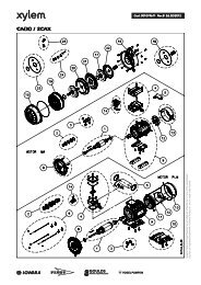
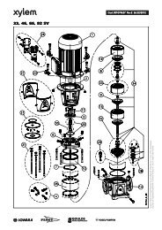
Teilbezeichnungen:<br />
1 Lau<strong>fr</strong>ad<br />
18/G Zwischenwand<br />
24 Welle<br />
412 Winkelmanschette<br />
447 Fe<strong>de</strong>r<br />
472 Gleitring<br />
474 Scheibe<br />
475 Gegenring<br />
481 Balg<br />
484.1 Winkelring<br />
485 Mitnehmer<br />
DR Drossel<br />
Teilbezeichnungen:<br />
1 Lau<strong>fr</strong>ad<br />
18/G Zwischenwand<br />
24 Welle<br />
GD1 Fe<strong>de</strong>r mit Mitnehmerwirkung<br />
GD2 O-Ring (Welle)<br />
GD3 Gleitringhalterung<br />
GD4 O-Ring (Gleitring)<br />
GD5 Gleitring<br />
GD6 Gegenring<br />
GD7 O-Ring (Gegenring)<br />
Pumpengröße d 1 d 7 d L l 1k Pumpengröße d 1 d 7 d L l 1k<br />
<strong>LM</strong> 65-315, <strong>LM</strong> 80-315<br />
<strong>LM</strong> 100-160, <strong>LM</strong> 100-200<br />
<strong>LM</strong> 100-250, <strong>LM</strong> 100-315<br />
<strong>LM</strong> 125-250<br />
40 58 32 45<br />
<strong>LM</strong> 125-200, <strong>LM</strong> 125-315<br />
<strong>LM</strong> 150-250, <strong>LM</strong> 150-315<br />
50 70 42 47,5<br />
<strong>LM</strong>N 32-125, <strong>LM</strong>N 32-160<br />
<strong>LM</strong>N 32-200, <strong>LM</strong>N 40-125<br />
<strong>LM</strong>N 40-160, <strong>LM</strong>N 40-200<br />
<strong>LM</strong>N 40-250, <strong>LM</strong>N 50-125<br />
<strong>LM</strong>N 50-160, <strong>LM</strong>N 50-200<br />
<strong>LM</strong>N 50-250, <strong>LM</strong>N 65-125<br />
<strong>LM</strong>N 65-160, <strong>LM</strong>N 65-200<br />
<strong>LM</strong>N 80-160<br />
22 37 18 37,5<br />
<strong>LM</strong>N 65-160, <strong>LM</strong>N 65-250<br />
<strong>LM</strong>N 80-200, <strong>LM</strong>N 80-250<br />
28 43 24 42,5<br />
<strong>LM</strong>N 80-250 33 43 29 42,5<br />
Die eingetragenen Maße entsprechen Gleitringdichtungen nach EN 12756 mit Baulänge l 1k.<br />
Maße in mm unverbindlich - Technische Än<strong>de</strong>rungen vorbehalten!<br />
<strong>LM</strong> ger/<strong>fr</strong>/eng Seite 6 Revision 06<br />
Artikel Nr. 771073101 Ausgabe 08/2013
Einbau-, Betriebs- und Wartungsanleitung<br />
<strong>Baureihe</strong> <strong>LM</strong>, <strong>LM</strong>N<br />
3.3.2 Allgemeine Hinweise<br />
Die Wie<strong>de</strong>rverwendung von Gleitringdichtungen,<br />
die bereits längere Zeit im Einsatz<br />
waren, birgt die Gefahr von Undichtheiten an<br />
<strong>de</strong>r Gleitfläche nach <strong>de</strong>m Wie<strong>de</strong>reinbau. Es<br />
wird daher <strong>de</strong>r Ersatz <strong>de</strong>r Gleitringdichtung<br />
durch eine neue empfohlen. Die ausgebaute<br />
Gleitringdichtung kann vom Hersteller überholt<br />
wer<strong>de</strong>n und als Ersatz-Gleitringdichtung dienen.<br />
3.3.3 Hinweise für die Montage<br />
Auf größte Sauberkeit achten! Beson<strong>de</strong>rs die<br />
Gleitflächen müssen sauber, trocken und<br />
unbeschädigt bleiben. Auch keine Schmiero<strong>de</strong>r<br />
Gleitmittel auf die Gleitflächen <strong>de</strong>r<br />
Gleitringdichtung auftragen.<br />
• Falls bei <strong>de</strong>r Ersatzgleitringdichtung Gleitmittel<br />
beigepackt ist, dann dieses verwen<strong>de</strong>n.<br />
Mineralische Fette o<strong>de</strong>r Öle nur dann<br />
verwen<strong>de</strong>n, wenn völlig sicher ist, dass die<br />
Elastomere <strong>de</strong>r Gleitringdichtung ölbeständig<br />
sind. Kein Silicon verwen<strong>de</strong>n.<br />
Nur Gleitmittel verwen<strong>de</strong>n, von <strong>de</strong>nen<br />
sichergestellt ist, dass es zwischen ihnen und<br />
<strong>de</strong>m För<strong>de</strong>rmedium zu keiner gefährlichen<br />
Reaktion kommen kann.<br />
Stellen Sie alle erfor<strong>de</strong>rlichen Teile bereit, damit<br />
die Montage zügig vor sich geht. Die Gleitmittel<br />
wirken nur kurze Zeit, so dass danach die<br />
Verschiebbarkeit und damit die automatische<br />
Einstellung <strong>de</strong>r Elastomere verloren geht.<br />
Schieben Sie die Elastomere nie über scharfe<br />
Kanten. Falls erfor<strong>de</strong>rlich Montagehülsen<br />
verwen<strong>de</strong>n.<br />
Gleitringdichtungen mit Faltenbälgen bei Montage<br />
so schieben, dass <strong>de</strong>r Balg zusammengedrückt<br />
und nicht gestreckt wird (Reißgefahr!).<br />
3.6 Richtwerte für Schalldruckpegel<br />
Nennleist<br />
Schalldruckpegel L pA in dB(A)<br />
ungsbed Pumpe alleine<br />
Pumpe + Motor<br />
arf P N in 2950 1450<br />
2950 1450<br />
kW min -1 min -1 min -1 min -1<br />
0,55 50,5 49,5 58,0 52,0<br />
0,75 52,0 51,0 59,0 54,0<br />
1,1 54,0 53,0 60,0 55,5<br />
1,5 55,5 55,0 63,5 57,0<br />
2,2 58,0 57,0 64,5 59,0<br />
3,0 59,5 58,5 68,5 61,0<br />
4,0 61,0 60,0 69,0 63,0<br />
5,5 63,0 62,0 70,0 65,0<br />
7,5 64,5 63,5 70,5 67,0<br />
11,0 66,5 65,5 72,0 69,0<br />
15,0 68,0 67,0 72,5 70,0<br />
18,5 69,0 68,5 73,0 70,5<br />
22,0 70,5 69,5 74,5 71,0<br />
30,0 72,0 71,0 75,0 72,0<br />
37,0 73,0 76,0<br />
45,0 74,0 77,0<br />
55,0 75,5 78,0<br />
Schalldruckpegel L pA gemessen in 1 m Abstand vom<br />
Pumpenumriss nach DIN 45635, Teil 1 und 24. Raum- und<br />
Fundamenteinflüsse sind nicht berücksichtigt. Die Toleranz für<br />
diese Werte beträgt 3 dB(A).<br />
Zuschlag bei 60 Hz-Betrieb:<br />
Pumpe allein: <br />
Pumpe mit Motor: +4 dB(A)<br />
3.7 Zulässige Stutzenkräfte und Momente<br />
an <strong>de</strong>n Pumpenstutzen ...<br />
... in Anlehnung an die Europump-Empfehlung für<br />
Pumpen nach ISO 5199.<br />
Die Angaben für Kräfte und Momente gelten nur für<br />
statische Rohrleitungslasten. Alle Werte für Kräfte und<br />
Momente sind auf <strong>de</strong>n Standardwerkstoff 0.6020<br />
(<strong>Baureihe</strong> <strong>LM</strong>N) bzw. 0.6025 (<strong>Baureihe</strong> <strong>LM</strong>) bezogen.<br />
3.4 Lagerung<br />
Die Lagerung erfolgt in <strong>de</strong>n Wälzlagern <strong>de</strong>s Motors.<br />
Die Lager sind auf Lebensdauer fettgeschmiert und<br />
somit wartungs<strong>fr</strong>ei.<br />
3.5 Kon<strong>de</strong>nswasser<br />
Bei Motoren, die starken Temperaturschwankungen<br />
o<strong>de</strong>r extremen klimatischen Verhältnissen ausgesetzt<br />
sind, empfehlen wir die Verwendung eines Motors mit<br />
Stillstandsheizung um eine Kon<strong>de</strong>nswasserbildung im<br />
Motorinneren zu verhin<strong>de</strong>rn. Während <strong>de</strong>s<br />
Motorbetriebes darf die Stillstandsheizung nicht<br />
eingeschaltet sein.<br />
Abb. 1<br />
<strong>LM</strong> ger/<strong>fr</strong>/eng Seite 7 Revision 06<br />
Artikel Nr. 771073101 Ausgabe 08/2013
Einbau-, Betriebs- und Wartungsanleitung<br />
<strong>Baureihe</strong> <strong>LM</strong>, <strong>LM</strong>N<br />
Saugstutzen<br />
Druckstutzen<br />
Baugrößen<br />
Kräfte in N<br />
Momente in Nm<br />
Kräfte in N<br />
Momente in Nm<br />
DN<br />
DN<br />
Fx Fy Fz F Mx My Mz M Fx Fy Fz F Mx My Mz M<br />
<strong>LM</strong>N 32-125 50 465 420 380 730 395 280 322 575 32 255 240 295 465 310 210 240 450<br />
<strong>LM</strong>N 32-160 50 465 420 380 730 395 280 322 575 32 255 240 295 465 310 210 240 450<br />
<strong>LM</strong>N 32-200 50 465 420 380 730 395 280 322 575 32 255 240 295 465 310 210 240 450<br />
<strong>LM</strong>N 40-125 65 590 520 475 925 420 310 335 615 40 310 280 350 550 365 255 295 535<br />
<strong>LM</strong>N 40-160 65 590 520 475 925 420 310 335 615 40 311 280 350 550 365 255 295 535<br />
<strong>LM</strong>N 40-200 65 590 520 475 925 420 310 335 615 40 312 280 350 550 365 255 295 535<br />
<strong>LM</strong>N 40-250 65 590 520 475 925 420 310 335 615 40 313 280 350 550 365 255 295 535<br />
<strong>LM</strong>N 50-125 65 590 520 475 925 420 310 335 615 50 420 380 465 730 395 280 325 575<br />
<strong>LM</strong>N 50-160 65 590 520 475 925 420 310 335 615 50 420 380 465 730 395 280 325 575<br />
<strong>LM</strong>N 50-200 65 590 520 475 925 420 310 335 615 50 420 380 465 730 395 280 325 575<br />
<strong>LM</strong>N 50-250 65 590 520 475 925 420 310 335 615 50 420 380 465 730 395 280 325 575<br />
<strong>LM</strong>N 65-125 80 700 630 575 1110 450 322 365 660 65 520 475 590 925 420 310 335 615<br />
<strong>LM</strong>N 65-160 80 700 630 575 1110 450 322 365 660 65 520 475 590 925 420 310 335 615<br />
<strong>LM</strong>N 65-200 80 700 630 575 1110 450 322 365 660 65 520 475 590 925 420 310 335 615<br />
<strong>LM</strong>N 65-250 80 700 630 575 1110 450 322 365 660 65 520 475 590 925 420 310 335 615<br />
<strong>LM</strong> 65-315 80 700 630 575 1110 450 322 365 660 65 520 475 590 925 420 310 335 615<br />
<strong>LM</strong>N 80-160 100 940 840 760 1470 490 350 410 730 80 630 575 700 1110 450 322 365 660<br />
<strong>LM</strong>N 80-200 100 941 840 760 1470 490 350 410 730 80 630 576 700 1110 450 322 365 660<br />
<strong>LM</strong>N 80-250 100 942 840 760 1470 490 350 410 730 80 630 577 700 1110 450 322 365 660<br />
<strong>LM</strong> 80-315 100 943 840 760 1470 490 350 410 730 80 630 578 700 1110 450 322 365 660<br />
<strong>LM</strong> 100-160 125 1110 1000 900 1740 590 420 535 855 100 840 760 940 1470 490 350 410 730<br />
<strong>LM</strong> 100-200 125 1110 1000 900 1740 590 420 535 855 100 840 760 940 1470 490 350 410 730<br />
<strong>LM</strong> 100-250 125 1110 1000 900 1740 590 420 535 855 100 840 760 940 1470 490 350 410 730<br />
<strong>LM</strong> 100-315 125 1110 1000 900 1740 590 420 535 855 100 840 760 940 1470 490 350 410 730<br />
<strong>LM</strong> 125-200 150 1400 1260 1140 2200 700 490 575 1025 125 1000 900 1110 1740 590 420 535 855<br />
<strong>LM</strong> 125-250 150 1400 1260 1140 2200 700 490 575 1025 125 1000 900 1110 1740 590 420 535 855<br />
<strong>LM</strong> 125-270 150 1400 1260 1140 2200 700 490 575 1025 125 1000 900 1110 1740 590 420 535 855<br />
<strong>LM</strong> 150-250 200 1880 1680 1510 2930 910 650 750 1350 150 1260 1140 1400 2200 700 490 575 1025<br />
<strong>LM</strong> 150-315 200 1880 1680 1510 2930 910 650 750 1350 150 1260 1140 1400 2200 700 490 575 1025<br />
3.8 Maximal zulässige Betriebsdrücke<br />
und Temperatur<br />
Grundsätzlich gelten die im Datenblatt und / o<strong>de</strong>r <strong>de</strong>r<br />
Auftragsbestätigung sowie am Leistungsschild<br />
angegebenen Werte bezüglich Drücke und<br />
Temperatur. Eine Über- o<strong>de</strong>r Unterschreitung dieser<br />
Werte ist unzulässig. Sind im Datenblatt und / o<strong>de</strong>r <strong>de</strong>r<br />
Auftragsbestätigung keine Drücke und / o<strong>de</strong>r<br />
Temperatur festgelegt, so gelten die folgen<strong>de</strong>n<br />
Grenzen für Zulaufdruck und Raumtemperatur:<br />
Zulaufdruck (Systemdruck) = Druck am<br />
Pumpeneintritt: max. 5 bar<br />
Raumtemperatur max. 40°C.<br />
Bei Einsatz <strong>de</strong>r Pumpen auch einschlägige Gesetze<br />
und Vorschriften beachten (z.B. DIN 4747 o<strong>de</strong>r DIN<br />
4752, Abschnitt 4.5).<br />
<strong>LM</strong> ger/<strong>fr</strong>/eng Seite 8 Revision 06<br />
Artikel Nr. 771073101 Ausgabe 08/2013
Einbau-, Betriebs- und Wartungsanleitung<br />
<strong>Baureihe</strong> <strong>LM</strong>, <strong>LM</strong>N<br />
4. Transport, Handhabung, Zwischenlagerung<br />
4.1 Transport, Handhabung<br />
• Überprüfen Sie die Pumpe / das Aggregat gleich<br />
bei Anlieferung bzw. Eingang <strong>de</strong>r Sendung auf<br />
Vollständigkeit o<strong>de</strong>r Schä<strong>de</strong>n.<br />
• Der Transport <strong>de</strong>r Pumpe / <strong>de</strong>s Aggregates muss<br />
fachgerecht und schonend durchgeführt wer<strong>de</strong>n.<br />
Harte Stöße unbedingt vermei<strong>de</strong>n.<br />
• Die bei Auslieferung vom Werk vorgegebene<br />
Transportlage beibehalten. Beachten Sie auch die<br />
auf <strong>de</strong>r Verpackung angebrachten Hinweise.<br />
• Saug- und Druckseite <strong>de</strong>r Pumpe müssen<br />
während Transport und Aufbewahrung mit<br />
Stopfen verschlossen bleiben.<br />
Entsorgen Sie die Verpackungsteile <strong>de</strong>n<br />
örtlichen Vorschriften entsprechend.<br />
• Hebehilfen (z.B. Stapler, Kran, Kranvorrichtung,<br />
Flaschenzüge, Anschlagseile, usw.) müssen<br />
ausreichend dimensioniert sein und dürfen nur<br />
von dazu befugten Personen bedient wer<strong>de</strong>n.<br />
• Das Anheben <strong>de</strong>r Pumpe / <strong>de</strong>s Aggregates darf<br />
nur an stabilen Aufhängungspunkten wie<br />
Gehäuse, Stutzen, Rahmen erfolgen. Bild 2 zeigt<br />
die richtige Handhabung bei Krantransport.<br />
Nicht unter schweben<strong>de</strong>n Lasten aufhalten,<br />
allgemeine Unfallverhütungsvorschriften beachten.<br />
Solange die Pumpe / das Aggregat<br />
nicht am endgültigen Aufstellungsort befestigt<br />
ist, muss es gegen Umkippen und Abrutschen<br />
gesichert sein.<br />
Die Anschlagseile dürfen nicht an <strong>de</strong>n Ringösen<br />
<strong>de</strong>s Motors o<strong>de</strong>r an Wellen befestigt wer<strong>de</strong>n.<br />
Ein Herausrutschen <strong>de</strong>r Pumpe / <strong>de</strong>s Aggregates<br />
aus <strong>de</strong>r Transportaufhängung kann Personen-<br />
und Sachschä<strong>de</strong>n verursachen.<br />
Bild 2<br />
4.2 Zwischenlagerung / Konservierung<br />
Pumpen o<strong>de</strong>r Aggregate, die vor <strong>de</strong>r Inbetriebnahme<br />
längere Zeit zwischengelagert wer<strong>de</strong>n (max. 6 Monate),<br />
vor Feuchtigkeit, Vibrationen und Schmutz schützen<br />
(z.B. durch Einschlagen in Ölpapier o<strong>de</strong>r Kunststofffolie).<br />
Die Aufbewahrung hat grundsätzlich an<br />
einem von äußeren Einflüssen geschützten Ort, z.B.<br />
unter trockenem Dach, zu erfolgen. Während dieser<br />
Zeit müssen Saug- und Druckstutzen sowie alle an<strong>de</strong>ren<br />
Zu- und Ablaufstutzen immer mit Blindflanschen<br />
o<strong>de</strong>r Blindstopfen verschlossen wer<strong>de</strong>n.<br />
Bei längeren Zwischenlagerungszeiten können Konservierungsmaßnahmen<br />
an bearbeiteten Bauteiloberflächen<br />
und eine Verpackung mit Feuchtigkeitsschutz<br />
notwendig wer<strong>de</strong>n!<br />
5. Aufstellung / Einbau<br />
5.1 Aufstellung <strong>de</strong>s Aggregates<br />
Die Pumpen müssen auf einem festen Unterbau festgeschraubt<br />
wer<strong>de</strong>n (z.B. Betonfundament, Stahlplatte,<br />
Stahlträger, etc.). Der Unterbau muss allen während<br />
<strong>de</strong>s Betriebes entstehen<strong>de</strong>n Belastungen standhalten.<br />
Die Bauwerkgestaltung muss gemäss <strong>de</strong>n<br />
Abmessungen <strong>de</strong>r Maßzeichnung vorbereitet sein. Die<br />
Betonfundamente sollen eine ausreichen<strong>de</strong><br />
Betonfestigkeit nach DIN 1045 o<strong>de</strong>r gleichwertiger<br />
Norm (min. BN 15) haben, um eine sichere,<br />
funktionsgerechte Aufstellung zu ermöglichen.<br />
Das Betonfundament muss abgebun<strong>de</strong>n haben, bevor<br />
das Aggregat aufgesetzt wird. Seine Oberfläche muss<br />
waagrecht und eben sein. Die Lage und Größe <strong>de</strong>r<br />
Pumpenfüße und <strong>de</strong>r Fundamentschrauben<br />
entnehmen Sie <strong>de</strong>r Maßzeichnung.<br />
Als Fundamentschrauben können Spreizanker,<br />
Klebeanker o<strong>de</strong>r mit <strong>de</strong>m Fundament vergossene<br />
Fundamentanker (Steinschrauben) verwen<strong>de</strong>t wer<strong>de</strong>n.<br />
Für Wartung und Instandhaltung ist genügend<br />
Raum vorzusehen, beson<strong>de</strong>rs für das Auswechseln<br />
<strong>de</strong>s Antriebsmotors o<strong>de</strong>r <strong>de</strong>s kompletten<br />
Pumpenaggregates. Der Lüfter <strong>de</strong>s<br />
Motors muss genügend Kühlluft ansaugen können.<br />
Daher ist min<strong>de</strong>stens 10 cm Abstand <strong>de</strong>s<br />
Ansauggitters zu einer Wand, etc. erfor<strong>de</strong>rlich.<br />
• Die Pumpe ist beim Aufsetzen auf das Fundament<br />
mit Hilfe einer Wasserwaage (am Druckstutzen)<br />
auszurichten. Die zulässige Lageabweichung beträgt<br />
0,2 mm/m. Unterlagsbleche müssen in unmittelbarer<br />
Nähe <strong>de</strong>r Fundamentanker eingesetzt<br />
wer<strong>de</strong>n und alle plan aufliegen.<br />
• Wer<strong>de</strong>n von benachbarten Anlagenbauteilen<br />
Schwingungen auf das Pumpenfundament<br />
übertragen, muss dieses durch entsprechen<strong>de</strong><br />
schwingungsdämpfen<strong>de</strong> Unterlagen abgeschirmt<br />
wer<strong>de</strong>n (Schwingungen von außen können die<br />
Lagerung beeinträchtigen).<br />
<strong>LM</strong> ger/<strong>fr</strong>/eng Seite 9 Revision 06<br />
Artikel Nr. 771073101 Ausgabe 08/2013
Einbau-, Betriebs- und Wartungsanleitung<br />
<strong>Baureihe</strong> <strong>LM</strong>, <strong>LM</strong>N<br />
• Soll die Übertragung von Schwingungen auf benachbarte<br />
Anlagenbauteile vermie<strong>de</strong>n wer<strong>de</strong>n, ist<br />
das Fundament auf entsprechen<strong>de</strong> schwingungsdämpfen<strong>de</strong><br />
Unterlagen zu grün<strong>de</strong>n.<br />
Die Dimensionierung dieser schwingungsisolieren<strong>de</strong>n<br />
Unterlagen ist für je<strong>de</strong>n Anwendungsfall<br />
verschie<strong>de</strong>n und soll daher von einem<br />
erfahrenen Fachmann durchgeführt wer<strong>de</strong>n.<br />
5.2 Anschluss <strong>de</strong>r Rohrleitungen an die<br />
Pumpe<br />
Die Pumpe darf auf keinen Fall als Festpunkt<br />
für die Rohrleitung verwen<strong>de</strong>t wer<strong>de</strong>n. Die<br />
zulässigen Rohrleitungskräfte dürfen nicht<br />
überschritten wer<strong>de</strong>n, siehe Kapitel 3.7.<br />
5.2.1 Saug- und Druckleitung<br />
• Die Rohrleitungen müssen so bemessen und<br />
ausgeführt sein, dass eine einwand<strong>fr</strong>eie<br />
Anströmung <strong>de</strong>r Pumpe gewährleistet ist und<br />
daher die Funktion <strong>de</strong>r Pumpe nicht beeinträchtigt<br />
wird. Beson<strong>de</strong>res Augenmerk ist auf die<br />
Luftdichtheit von Saugleitungen und Einhaltung<br />
<strong>de</strong>r NPSH-Werte zu legen. Bei Saugbetrieb die<br />
Saugleitung im horizontalen Teil zur Pumpe leicht<br />
steigend verlegen, so dass keine Luftsäcke<br />
entstehen. Bei Zulaufbetrieb die Zulaufleitung<br />
leicht fallend zur Pumpe verlegen. Keine<br />
Armaturen o<strong>de</strong>r Krümmer unmittelbar vor <strong>de</strong>m<br />
Pumpeneintritt vorsehen.<br />
• Bei För<strong>de</strong>rung aus unter Vakuum stehen<strong>de</strong>n<br />
Behältern ist die Anordnung einer<br />
Vakuumausgleichsleitung vorteilhaft. Die<br />
Rohrleitung soll eine Min<strong>de</strong>stnennweite von 25<br />
mm aufweisen und muss über <strong>de</strong>m höchsten im<br />
Behälter zulässigen Flüssigkeitsstand mün<strong>de</strong>n.<br />
• Eine zusätzliche absperrbare Rohrleitung (Bild 3) -<br />
Pumpendruckstutzen-Ausgleichsleitung - erleichtert<br />
das Entlüften <strong>de</strong>r Pumpe vor <strong>de</strong>m Anfahren.<br />
• Vor Anschluss an die Pumpe: Schutzab<strong>de</strong>ckungen<br />
<strong>de</strong>r Pumpenstutzen entfernen.<br />
• Vor Inbetriebnahme muss das Rohrsystem,<br />
installierte Armaturen und Apparate von<br />
Schweißperlen, Zun<strong>de</strong>r usw. gereinigt wer<strong>de</strong>n.<br />
Anlagen, die in direktem o<strong>de</strong>r indirektem<br />
Zusammenhang mit Trinkwassersystemen<br />
stehen, sind vor Einbau und Inbetriebnahme von<br />
eventuellen Verunreinigungen sicher zu be<strong>fr</strong>eien.<br />
• Zum Schutz <strong>de</strong>r Wellenabdichtung (insbeson<strong>de</strong>re<br />
Gleitringdichtungen) vor Fremdkörpern empfohlen<br />
im Anfahrbetrieb: Sieb 800 Mikron in Saug- /<br />
Zulaufleitung.<br />
• Wird das Rohrsystem mit eingebauter Pumpe<br />
abgedrückt, dann: maximal zulässigen<br />
Gehäuseenddruck <strong>de</strong>r Pumpe bzw. <strong>de</strong>r<br />
Wellenabdichtung beachten, siehe Datenblatt und<br />
/ o<strong>de</strong>r <strong>de</strong>r Auftragsbestätigung.<br />
• Bei Entleerung <strong>de</strong>r Rohrleitung nach Druckprobe<br />
Pumpe entsprechend konservieren (sonst<br />
Festrosten und Probleme bei Inbetriebnahme).<br />
5.2.2 Zusatzanschlüsse<br />
Folgen<strong>de</strong> Zusatzanschlüsse sind vorhan<strong>de</strong>n:<br />
Anschluss Beschreibung Dimension<br />
E Entleerung <strong>de</strong>r Pumpe R3/8"<br />
LA Leckflüssigkeit R1/2"<br />
M Manometer R1/4"<br />
V*) Vakuummeter*) R1/4"<br />
*) ... optional, auf Wunsch gebohrt<br />
Bild 3<br />
• Achten Sie bei <strong>de</strong>r Leitungsführung auf die<br />
Zugängigkeit zur Pumpe bezüglich Wartung,<br />
Montage, Demontage und Entleerung.<br />
• "Zulässige Stutzenkräfte und Momente an <strong>de</strong>n<br />
Pumpenstutzen ..." (Kapitel 3.7) beachten.<br />
• Wenn in <strong>de</strong>n Rohrleitungen Kompensatoren<br />
verwen<strong>de</strong>t wer<strong>de</strong>n, so sind diese so abzufangen,<br />
dass die Pumpe nicht durch <strong>de</strong>n Druck in <strong>de</strong>r<br />
Rohrleitung unzulässig hoch belastet wird.<br />
5.3 Antrieb<br />
Die Motorausführung ihrer Pumpe entnehmen Sie <strong>de</strong>r<br />
Auftragsbestätigung und <strong>de</strong>m Motorleistungsschild.<br />
Die Betriebsanleitung <strong>de</strong>s Motorherstellers ist zu<br />
beachten.<br />
Wenn im Zuge <strong>de</strong>r Reparatur ein neuer Motor<br />
verwen<strong>de</strong>t wird, dann ist folgen<strong>de</strong>s zu beachten:<br />
• Der Motor muss <strong>de</strong>n in Blatt 1130.1A608D<br />
genannten Anfor<strong>de</strong>rungen entsprechen (bei<br />
Bedarf beim Pumpenlieferanten anfor<strong>de</strong>rn).<br />
• Motorstummel und Motorflansch <strong>de</strong>s neuen<br />
Motors gut säubern (Lackreste entfernen).<br />
<strong>LM</strong> ger/<strong>fr</strong>/eng Seite 10 Revision 06<br />
Artikel Nr. 771073101 Ausgabe 08/2013
Einbau-, Betriebs- und Wartungsanleitung<br />
<strong>Baureihe</strong> <strong>LM</strong>, <strong>LM</strong>N<br />
5.4 Elektrischer Anschluss<br />
Der Elektroanschluss darf nur durch einen<br />
befugten Elektrofachmann erfolgen. Die in <strong>de</strong>r<br />
Elektrotechnik gültigen Regeln und Vorschriften,<br />
insbeson<strong>de</strong>re hinsichtlich Schutzmaßnahmen<br />
sind zu beachten. Die Vorschriften <strong>de</strong>r<br />
örtlichen nationalen Energieversorgungsunternehmen<br />
sind ebenso einzuhalten.<br />
Vor Beginn <strong>de</strong>r Arbeiten die Angaben auf <strong>de</strong>m<br />
Motorleistungsschild auf Übereinstimmung mit <strong>de</strong>m<br />
örtlichen Stromnetz überprüfen. Das Anklemmen <strong>de</strong>r<br />
Stromzuführungskabel <strong>de</strong>s gekuppelten Antriebsmotors<br />
ist entsprechend <strong>de</strong>m Schaltplan <strong>de</strong>s<br />
Motorherstellers vorzunehmen. Ein Motorschutzschalter<br />
ist vorzusehen.<br />
Eine Überprüfung <strong>de</strong>r Drehrichtung darf nur bei<br />
gefüllter Pumpe erfolgen. Je<strong>de</strong>r Trockenlauf<br />
führt zu Zerstörungen an <strong>de</strong>r Pumpe.<br />
5.5 Endkontrolle<br />
Das Aggregat muss sich an <strong>de</strong>r Steckwelle von Hand<br />
leicht durchdrehen lassen.<br />
6. Inbetriebnahme, Betrieb, Außerbetriebnahme<br />
Die Anlage darf nur von Personal in Betrieb<br />
genommen wer<strong>de</strong>n, das mit <strong>de</strong>n örtlichen<br />
Sicherheitsbestimmungen und mit dieser<br />
Betriebsanleitung (insbeson<strong>de</strong>re mit <strong>de</strong>n darin<br />
enthaltenen Sicherheitsvorschriften und<br />
Sicherheitshinweisen) vertraut ist.<br />
6.1 Erstinbetriebnahme<br />
Vor <strong>de</strong>m Einschalten <strong>de</strong>r Pumpe muss sichergestellt<br />
sein, dass nachstehen<strong>de</strong> Punkte geprüft und<br />
durchgeführt wur<strong>de</strong>n:<br />
• Vor <strong>de</strong>r Erstinbetriebnahme sind keine Schmiermaßnahmen<br />
notwendig.<br />
• Pumpe und Saugleitung müssen bei<br />
Inbetriebnahme vollständig mit Flüssigkeit gefüllt<br />
sein.<br />
• Bei Drehzahlen unter 1000 min -1<br />
(drehzahlgeregelte Anlagen) muß bei vertikaler<br />
Einbaulage vor <strong>de</strong>r Erstinbetriebnahme <strong>de</strong>r<br />
Gleitringdichtungsraum entlüftet wer<strong>de</strong>n.<br />
• Aggregat noch einmal von Hand aus durchdrehen<br />
und leichten, gleichmäßigen Gang prüfen.<br />
• Kontrollieren, ob Laternenschutzbleche montiert<br />
sind und alle Sicherheitseinrichtungen betriebsbereit<br />
sind.<br />
• Schieber in Saug- bzw. Zulaufleitung öffnen.<br />
• Druckseitigen Schieber auf ca. 25% <strong>de</strong>r<br />
Auslegungs-För<strong>de</strong>rmenge einstellen. Bei Pumpen<br />
mit Druckstutzen-Nennweite kleiner DN 200 kann<br />
<strong>de</strong>r Schieber beim Anfahren auch geschlossen<br />
bleiben.<br />
• Sicherstellen, dass das Aggregat vorschriftgerecht<br />
elektrisch mit allen Schutzeinrichtungen angeschlossen<br />
ist.<br />
• Kurz Ein- und Ausschalten und dabei<br />
Drehrichtung kontrollieren. Sie muss <strong>de</strong>m<br />
Drehrichtungspfeil auf <strong>de</strong>r Antriebslaterne<br />
entsprechen.<br />
6.2 Antriebsmaschine einschalten.<br />
• Sofort (max. 30 Sekun<strong>de</strong>n bei 50 Hz bzw. max. 20<br />
Sekun<strong>de</strong>n bei 60 Hz Stromversorgung) nach <strong>de</strong>m<br />
Hochlauf auf die Betriebsdrehzahl druckseitigen<br />
Schieber öffnen und damit <strong>de</strong>n gewünschten<br />
Betriebspunkt einstellen. Die am Typenschild bzw.<br />
im Datenblatt und / o<strong>de</strong>r <strong>de</strong>r Auftragsbestätigung<br />
angegebenen För<strong>de</strong>rdaten müssen eingehalten<br />
wer<strong>de</strong>n. Je<strong>de</strong> Än<strong>de</strong>rung ist nur nach Rücksprache<br />
mit <strong>de</strong>m Hersteller zulässig!<br />
Der Betrieb mit geschlossenem Absperrorgan in<br />
<strong>de</strong>r Saug- und / o<strong>de</strong>r Druckleitung ist nicht<br />
zulässig.<br />
Bei Anfahren gegen fehlen<strong>de</strong>n Gegendruck ist<br />
dieser durch druckseitiges Drosseln herzustellen<br />
(Schieber nur wenig öffnen). Nach<br />
Erreichen <strong>de</strong>s vollen Gegendruckes Schieber<br />
öffnen.<br />
Erreicht die Pumpe nicht die vorgesehene<br />
För<strong>de</strong>rhöhe o<strong>de</strong>r treten atypische Geräusche<br />
o<strong>de</strong>r Schwingungen auf: Pumpe wie<strong>de</strong>r außer<br />
Betrieb setzen (siehe Kapitel 6.7) und Ursache<br />
suchen (siehe Kapitel 10).<br />
6.3 Wie<strong>de</strong>rinbetriebnahme<br />
Bei je<strong>de</strong>r Wie<strong>de</strong>rinbetriebnahme ist grundsätzlich wie<br />
bei <strong>de</strong>r Erstinbetriebnahme vorzugehen. Die Kontrolle<br />
von Drehrichtung und Leichtgängigkeit <strong>de</strong>s<br />
Aggregates kann jedoch entfallen.<br />
Eine automatische Wie<strong>de</strong>rinbetriebnahme darf nur<br />
dann erfolgen, wenn sichergestellt ist, dass die Pumpe<br />
bei Stillstand mit Flüssigkeit gefüllt bleibt.<br />
Beson<strong>de</strong>re Vorsicht vor Berührung heißer<br />
Maschinenteile und im ungeschützten Bereich<br />
<strong>de</strong>r Wellenabdichtung. Automatisch gesteuerte<br />
Anlagen können sich je<strong>de</strong>rzeit und<br />
überraschend einschalten. Anlagenseitig<br />
entsprechen<strong>de</strong> Warnschil<strong>de</strong>r anbringen.<br />
6.4 Grenzen <strong>de</strong>s Betriebes<br />
Die Einsatzgrenzen <strong>de</strong>r Pumpe / <strong>de</strong>s<br />
Aggregates bezüglich Druck, Temperatur,<br />
Leistung und Drehzahl sind im Datenblatt und /<br />
o<strong>de</strong>r <strong>de</strong>r Auftragsbestätigung angegeben und<br />
unbedingt einzuhalten!<br />
<strong>LM</strong> ger/<strong>fr</strong>/eng Seite 11 Revision 06<br />
Artikel Nr. 771073101 Ausgabe 08/2013
Einbau-, Betriebs- und Wartungsanleitung<br />
<strong>Baureihe</strong> <strong>LM</strong>, <strong>LM</strong>N<br />
• Die auf <strong>de</strong>m Typenschild <strong>de</strong>r Antriebsmaschine<br />
angegebene Leistung darf nicht überschritten<br />
wer<strong>de</strong>n.<br />
• Plötzlich auftreten<strong>de</strong> Temperaturän<strong>de</strong>rungen<br />
(Temperaturschocks) sind zu vermei<strong>de</strong>n.<br />
• Pumpe und Antriebsmaschine sollen gleichmäßig<br />
und erschütterungs<strong>fr</strong>ei laufen, min<strong>de</strong>stens<br />
wöchentlich kontrollieren.<br />
6.4.1 För<strong>de</strong>rstrom min. / max.<br />
Sofern in <strong>de</strong>n Kennlinien o<strong>de</strong>r Datenblättern keine<br />
an<strong>de</strong>ren Angaben gemacht sind, gilt:<br />
Q min = 0,1 x Q BEP für Kurzzeitbetrieb<br />
Q min = 0,3 x Q BEP für Dauerbetrieb<br />
Q max = 1,2 x Q BEP für Dauerbetrieb *)<br />
Q BEP = För<strong>de</strong>rstrom im Wirkungsgradoptimum<br />
*) unter <strong>de</strong>r Voraussetzung NPSH Anlage > (NPSH Pumpe + 0,5 m)<br />
6.4.2 Abrasive Medien<br />
Beim För<strong>de</strong>rn von Flüssigkeiten mit abrasiven<br />
Bestandteilen ist ein erhöhter Verschleiß an<br />
Hydraulik und Wellenabdichtung zu erwarten.<br />
Die Inspektionsintervalle sollen gegenüber <strong>de</strong>n<br />
üblichen Zeiten reduziert wer<strong>de</strong>n.<br />
6.4.3 Zulässige Schalthäufigkeit<br />
Die zulässige Schalthäufigkeit <strong>de</strong>r Pumpe darf nicht<br />
überschritten wer<strong>de</strong>n, siehe Diagramm 6.<br />
max. zulässige Anläufe pro Stun<strong>de</strong><br />
100,0<br />
10,0<br />
1,0<br />
1 10 100 1000<br />
Motorleistung [kW]<br />
Diagramm 6<br />
Bei Elektromotoren ist die zulässige Schalthäufigkeit<br />
<strong>de</strong>r Betriebs- und Wartungsanleitung <strong>de</strong>s<br />
Motorlieferanten zu entnehmen.<br />
Bei von einan<strong>de</strong>r abweichen<strong>de</strong>n Werten ist die<br />
kleinere Schalthäufigkeit zulässig.<br />
6.5 Schmierung<br />
Der Pumpenteil hat keine Lager und muss somit nicht<br />
geschmiert wer<strong>de</strong>n.<br />
Für die möglicherweise erfor<strong>de</strong>rliche Schmierung <strong>de</strong>r<br />
Motorlager bitte die Empfehlung in <strong>de</strong>r Betriebs- und<br />
Wartungsanleitung <strong>de</strong>s Motorlieferanten beachten.<br />
6.6 Überwachung<br />
Regelmäßig durchgeführte Überwachungs- und<br />
Wartungsarbeiten verlängern die Lebensdauer<br />
Ihrer Pumpe o<strong>de</strong>r Anlage.<br />
• Pumpen, die funktionsbedingt einem chemischen<br />
Angriff bzw. abrasiven Verschleiß ausgesetzt sind,<br />
müssen periodisch auf chemischen o<strong>de</strong>r abrasiven<br />
Abtrag inspiziert wer<strong>de</strong>n. Die Erstinspektion<br />
ist nach einem halben Jahr durchzuführen. Alle<br />
weiteren Inspektionsintervalle sind auf Grund <strong>de</strong>s<br />
jeweiligen Zustan<strong>de</strong>s <strong>de</strong>r Pumpe festzulegen.<br />
6.7 Außerbetriebnahme<br />
• Schieber in <strong>de</strong>r Druckleitung unmittelbar (max. 10<br />
Sekun<strong>de</strong>n) vor Abschaltung <strong>de</strong>s Motors schließen.<br />
Nicht erfor<strong>de</strong>rlich, wenn druckbelastete Rückschlagklappe<br />
vorhan<strong>de</strong>n ist.<br />
• Antriebsmaschine abschalten. Auf ruhigen Auslauf<br />
achten.<br />
• Schieber auf <strong>de</strong>r Saugseite schließen.<br />
• Bei Frostgefahr Pumpe und Leitungen vollständig<br />
entleeren.<br />
6.8 Zwischenlagerung / Längerer Stillstand<br />
6.8.1 Zwischenlagerung neuer Pumpen<br />
Wenn die Inbetriebnahme längere Zeit nach <strong>de</strong>r Lieferung<br />
erfolgen soll, empfehlen wir zur Zwischenlagerung<br />
<strong>de</strong>r Pumpe die folgen<strong>de</strong>n Maßnahmen:<br />
• Pumpe an einem trockenen Ort lagern.<br />
• Durchdrehen <strong>de</strong>r Pumpe von Hand einmal<br />
monatlich.<br />
6.8.2 Maßnahmen für längere Außerbetriebnahme<br />
Pumpe bleibt eingebaut mit Betriebsbereitschaft:<br />
• In regelmäßigen Abstän<strong>de</strong>n sind Probeläufe von<br />
einer Dauer von min<strong>de</strong>stens 5 Minuten durchzuführen.<br />
Die Zeitspanne zwischen <strong>de</strong>n Probeläufen<br />
hängt von <strong>de</strong>r Anlage ab, sollte jedoch min<strong>de</strong>stens<br />
1x pro Woche durchgeführt wer<strong>de</strong>n.<br />
6.8.3 Längerer Stillstand<br />
Inbetriebnahme ist als Erstinbetriebnahme zu<br />
verstehen (siehe Kapitel 6).<br />
a) Gefüllte Pumpen<br />
• Reservepumpen 1x wöchentlich kurz ein- und<br />
sofort wie<strong>de</strong>r ausschalten. Eventuell alternativ als<br />
Hauptpumpe betreiben.<br />
• Steht die Reservepumpe unter Druck und<br />
Temperatur: alle vorhan<strong>de</strong>nen Sperr- und<br />
Spülsysteme eingeschaltet lassen.<br />
• Nach 5 Jahren Motorlager erneuern.<br />
b) Leerstehen<strong>de</strong> Pumpen<br />
• Min<strong>de</strong>stens 1x wöchentlich von Hand aus<br />
durchdrehen (nicht einschalten wegen<br />
Trockenlauf).<br />
• Nach 5 Jahren Motorlager erneuern.<br />
<strong>LM</strong> ger/<strong>fr</strong>/eng Seite 12 Revision 06<br />
Artikel Nr. 771073101 Ausgabe 08/2013
Einbau-, Betriebs- und Wartungsanleitung<br />
<strong>Baureihe</strong> <strong>LM</strong>, <strong>LM</strong>N<br />
7. Instandhaltung, Wartung<br />
7.1 Allgemeine Hinweise<br />
Arbeiten an <strong>de</strong>r Pumpe o<strong>de</strong>r Anlage sind nur im<br />
Stillstand durchzuführen. Beachten Sie<br />
unbedingt Kapitel 2.<br />
Instandhaltungsarbeiten und Wartung darf nur<br />
von geschultem und erfahrenem Personal, das<br />
mit <strong>de</strong>m Inhalt dieser Betriebsanleitung vertraut<br />
ist o<strong>de</strong>r vom Service-Personal <strong>de</strong>s Herstellers<br />
durchgeführt wer<strong>de</strong>n.<br />
7.2 Gleitringdichtungen<br />
Vor <strong>de</strong>m Öffnen <strong>de</strong>r Pumpe unbedingt Kapitel 2<br />
und Kapitel 8 beachten.<br />
Tritt bei <strong>de</strong>r Gleitringdichtung tropfenweise<br />
För<strong>de</strong>rmedium aus, so ist diese beschädigt und muss<br />
ersetzt wer<strong>de</strong>n.<br />
7.3 Motorlager<br />
Nach durchschnittlich 5 Jahren ist das Fett in <strong>de</strong>n<br />
Motorlagern so gealtert, dass ein Austausch <strong>de</strong>r Lager<br />
empfehlenswert ist. Jedoch sind die Lager nach<br />
spätestens 25000 Betriebsstun<strong>de</strong>n zu ersetzen bzw.<br />
entsprechend <strong>de</strong>r Wartungsanleitung <strong>de</strong>s Motorlieferanten,<br />
wenn dieser eine kürzere Wartungsdauer<br />
empfiehlt.<br />
7.4 Reinigung <strong>de</strong>r Pumpe<br />
• Äußerliche Verschmutzung an <strong>de</strong>r Pumpe<br />
beeinträchtigt die Wärmeabführung. Daher ist in<br />
regelmäßigen Abstän<strong>de</strong>n (je nach<br />
Verschmutzungsgrad) die Pumpe mit Wasser zu<br />
reinigen.<br />
Die Pumpe darf nicht mit unter Druck<br />
stehen<strong>de</strong>m Wasser (z.B. Hochdruckreiniger)<br />
gereinigt wer<strong>de</strong>n - Wassereintritt in Lager.<br />
8. Demontage <strong>de</strong>r Pumpe und Reparatur<br />
8.1 Allgemeine Hinweise<br />
Reparaturen an <strong>de</strong>r Pumpe o<strong>de</strong>r Anlage dürfen<br />
nur von autorisiertem Fachpersonal o<strong>de</strong>r durch<br />
Fachpersonal <strong>de</strong>s Herstellers durchgeführt<br />
wer<strong>de</strong>n.<br />
Bei Ausbau <strong>de</strong>r Pumpe unbedingt Kapitel 2<br />
sowie Kapitel 4.1 beachten.<br />
• Für Montagen und Reparaturen stehen auf<br />
Anfor<strong>de</strong>rung geschulte Kun<strong>de</strong>ndienst-Monteure<br />
zur Verfügung.<br />
Pumpen, die gesundheitsgefähr<strong>de</strong>n<strong>de</strong> Flüssigkeiten<br />
för<strong>de</strong>rn, müssen <strong>de</strong>kontaminiert wer<strong>de</strong>n.<br />
Beim Ablassen <strong>de</strong>s För<strong>de</strong>rmediums ist darauf<br />
zu achten, dass keine Gefährdungen für<br />
Personen und Umwelt entsteht. Gesetzliche<br />
Bestimmungen sind einzuhalten, ansonsten<br />
besteht Lebensgefahr!<br />
• Vor Beginn <strong>de</strong>r Demontage muss das Aggregat so<br />
gesichert wer<strong>de</strong>n, dass es nicht eingeschaltet<br />
wer<strong>de</strong>n kann.<br />
• Das Pumpengehäuse muss drucklos und entleert<br />
sein.<br />
• Alle Absperrorgane in <strong>de</strong>r Saug-, Zulauf- und<br />
Druckleitung müssen geschlossen sein.<br />
• Alle Teile müssen Umgebungstemperatur<br />
angenommen haben.<br />
Ausgebaute Pumpe, Baugruppen o<strong>de</strong>r<br />
Einzelteile gegen Umkippen o<strong>de</strong>r Wegrollen<br />
sichern.<br />
Offene Flamme (Lötlampe, etc.) beim Zerlegen<br />
nur dann als Hilfe verwen<strong>de</strong>n, wenn dadurch<br />
keine Brand- o<strong>de</strong>r Explosionsgefahr o<strong>de</strong>r die<br />
Gefahr <strong>de</strong>r Entwicklung schädlicher Dämpfe<br />
entsteht.<br />
Nur Original-Ersatzteile verwen<strong>de</strong>n. Auf<br />
richtigen Werkstoff und passen<strong>de</strong> Ausführung<br />
achten.<br />
8.2 Allgemeines<br />
Demontage und Montage grundsätzlich nach <strong>de</strong>r<br />
zugehörigen Schnittzeichnung (im Anhang)<br />
durchführen.<br />
Es ist nur han<strong>de</strong>lsübliches Werkzeug erfor<strong>de</strong>rlich.<br />
Vor <strong>de</strong>m Zerlegen prüfen, ob die erfor<strong>de</strong>rlichen<br />
Ersatzteile bereit liegen.<br />
Die Pumpe immer nur so weit zerlegen, als dies für<br />
<strong>de</strong>n Austausch <strong>de</strong>s zu reparieren<strong>de</strong>n Teils erfor<strong>de</strong>rlich<br />
ist.<br />
9. Ersatzteilempfehlung, Reservepumpen<br />
9.1 Ersatzteile<br />
Die Ersatzteile sind für die Bedingungen eines<br />
zweijährigen Dauerbetriebes auszuwählen. Falls keine<br />
an<strong>de</strong>ren Richtlinien zu beachten sind, wer<strong>de</strong>n die in<br />
unten angeführter Liste angegebenen Stückzahlen für<br />
Ersatzteile empfohlen (nach DIN 24296).<br />
<strong>LM</strong> ger/<strong>fr</strong>/eng Seite 13 Revision 06<br />
Artikel Nr. 771073101 Ausgabe 08/2013
Einbau-, Betriebs- und Wartungsanleitung<br />
<strong>Baureihe</strong> <strong>LM</strong>, <strong>LM</strong>N<br />
Zur Sicherung einer optimalen Verfügbarkeit<br />
empfehlen wir, insbeson<strong>de</strong>re bei Ausführungen<br />
aus Son<strong>de</strong>rwerkstoffen und Gleitringdichtung,<br />
auf Grund <strong>de</strong>r längeren Beschaffungszeiten<br />
entsprechen<strong>de</strong> Ersatzteile zu bevorraten.<br />
Anzahl <strong>de</strong>r Pumpen<br />
(einschließlich Reservepumpen)<br />
2 3 4 5 6/7 8/9 10/+<br />
Ersatzteile<br />
Stückzahl <strong>de</strong>r Ersatzteile<br />
Lau<strong>fr</strong>ad 1 1 1 2 2 2 20%<br />
Welle mit Passfe<strong>de</strong>rn<br />
und Muttern<br />
1 1 1 2 2 2 20%<br />
Dichtungen für<br />
Pumpengehäuse Sätze<br />
4 6 8 8 9 12 150%<br />
sonstige Dichtungen 4 6 8 8 9 10 100%<br />
Sätze<br />
Gleitringdichtung Satz 1 1 2 2 2 3 25%<br />
Ersatzteilbestellung<br />
Bei Ersatzteilbestellung bitten wir Sie um folgen<strong>de</strong><br />
Angaben:<br />
• Type: ______________________________________________________________________<br />
• S/N (Auftrags Nr.) ___________________________________________________<br />
• Teilebezeichnungen _______________________________________________<br />
• Schnittzeichnung ____________________________________________________<br />
Alle Angaben fin<strong>de</strong>n Sie auf <strong>de</strong>m Datenblatt und / o<strong>de</strong>r<br />
<strong>de</strong>r Auftragsbestätigung und <strong>de</strong>r dazugehörigen<br />
Schnittzeichnung.<br />
Ersatzteile in trockenen Räumen und vor<br />
Schmutz geschützt aufbewahren!<br />
9.2 Reservepumpen<br />
Für Pumpen in Anlagen, <strong>de</strong>ren Ausfall<br />
Menschenleben gefähr<strong>de</strong>n bzw. hohe<br />
Sachschä<strong>de</strong>n o<strong>de</strong>r Kosten verursachen können,<br />
ist unbedingt eine ausreichen<strong>de</strong> Anzahl von<br />
Reservepumpen in <strong>de</strong>r Anlage betriebsbereit zu<br />
halten. Die Betriebsbereitschaft ist durch<br />
laufen<strong>de</strong> Kontrolle sicherzustellen, siehe Kapitel<br />
6.8.<br />
Reservepumpen entsprechend Kapitel 6.8<br />
aufbewahren!<br />
<strong>LM</strong> ger/<strong>fr</strong>/eng Seite 14 Revision 06<br />
Artikel Nr. 771073101 Ausgabe 08/2013
Einbau-, Betriebs- und Wartungsanleitung<br />
<strong>Baureihe</strong> <strong>LM</strong>, <strong>LM</strong>N<br />
10. Störungen - Ursachen und Behebung<br />
Die angeführten Hinweise auf Ursachen und<br />
Behebung von Störungen sollen zur Erkennung <strong>de</strong>s<br />
Problems dienen. Für Störungen, die <strong>de</strong>r Betreiber<br />
nicht selbst beseitigen kann o<strong>de</strong>r will, steht <strong>de</strong>r<br />
Kun<strong>de</strong>ndienst <strong>de</strong>s Herstellers zur Verfügung. Bei<br />
Reparaturen und Än<strong>de</strong>rungen an <strong>de</strong>r Pumpe durch<br />
<strong>de</strong>n Betreiber sind beson<strong>de</strong>rs die Auslegungsdaten<br />
auf <strong>de</strong>m Datenblatt und / o<strong>de</strong>r <strong>de</strong>r Auftragsbestätigung<br />
sowie Kapitel 2 dieser Betriebsanleitung zu beachten.<br />
Gegebenenfalls ist das schriftliche Einverständnis <strong>de</strong>s<br />
Herstellers einzuholen.<br />
För<strong>de</strong>rstrom zu gering<br />
För<strong>de</strong>rstrom hört nach einiger Zeit auf<br />
För<strong>de</strong>rhöhe zu gering<br />
För<strong>de</strong>rhöhe zu hoch<br />
Antriebsmaschine überlastet<br />
Unruhiger Lauf <strong>de</strong>r Pumpe<br />
Zu hohe Temperatur in <strong>de</strong>r Pumpe<br />
Zu hohe Temperatur an <strong>de</strong>r<br />
Wellendichtung<br />
Zu hohe Temperatur an <strong>de</strong>r Lagerung<br />
Undichtheit an <strong>de</strong>r Pumpe<br />
Zu starke Leckage <strong>de</strong>r Wellendichtung<br />
Ursache<br />
Behebung<br />
■ Gegendruck zu hoch Anlage auf Verunreinigungen überprüfen, Schieber geöffnet<br />
Wi<strong>de</strong>rstän<strong>de</strong> in <strong>de</strong>r Druckleitung vermin<strong>de</strong>rn (Filter reinigen, ...)<br />
größeres Lau<strong>fr</strong>ad verwen<strong>de</strong>n (Antriebsleistung beachten)<br />
■ ■ ■ Gegendruck zu gering, För<strong>de</strong>rstrom zu groß druckseitigen Schieber drosseln<br />
■ ■ Drehzahl zu hoch Drehzahl verringern<br />
Drehzahl <strong>de</strong>r Antriebsmaschine mit vorgeschriebener<br />
Pumpendrehzahl (Leistungsschild) vergleichen<br />
Bei Drehzahlregelung (Frequenzumformer) Sollwert-<br />
Einstellung kontrollieren<br />
■ ■ Drehzahl zu klein Drehzahl erhöhen (verfügbare Antriebsleistung beachten)<br />
Drehzahl <strong>de</strong>r Antriebsmaschine mit vorgeschriebener<br />
Pumpendrehzahl (Leistungsschild) vergleichen<br />
Bei Drehzahlregelung (Frequenzumformer) Sollwert-<br />
Einstellung kontrollieren<br />
■ ■ ■ ■ För<strong>de</strong>rstrom zu klein Min<strong>de</strong>stför<strong>de</strong>rmenge vergrößern (Schieber öffnen, Bypass)<br />
■ För<strong>de</strong>rstrom zu groß För<strong>de</strong>rmenge verringern (Schieber drosseln)<br />
■ ■ Lau<strong>fr</strong>addurchmesser zu groß kleineres Lau<strong>fr</strong>ad verwen<strong>de</strong>n<br />
■ ■ Lau<strong>fr</strong>addurchmesser zu klein größeres Lau<strong>fr</strong>ad verwen<strong>de</strong>n (verfügbare Antriebsleistung<br />
beachten)<br />
■ ■ ■ ■ Pumpe und / o<strong>de</strong>r Rohrleitung nicht völlig mit Flüssigkeit füllen<br />
gefüllt<br />
entlüften<br />
■ ■ ■ Pumpe o<strong>de</strong>r Saug- / Zulaufleitung verstopft reinigen<br />
■ ■ Luftsack in Rohrleitung entlüften<br />
Leitungsführung verbessern<br />
■ ■ ■ ■ ■ Saughöhe zu groß / NPSH <strong>de</strong>r Anlage zu klein Flüssigkeitsspiegel erhöhen<br />
Vordruck erhöhen<br />
Wi<strong>de</strong>rstän<strong>de</strong> <strong>de</strong>r Zulauf- / Saugleitung verringern (Verlauf und<br />
Nennweite än<strong>de</strong>rn, Absperrorgane öffnen, Siebe reinigen)<br />
■ ■ ■ Luft wird angesaugt Flüssigkeitsspiegel erhöhen<br />
Vakuumdichtheit <strong>de</strong>r Saugleitung prüfen und herstellen<br />
■ ■ ■ Ansaugen von Luft durch die Wellenabdichtung Sperrleitung reinigen<br />
Sperrdruck erhöhen<br />
Wellenabdichtung erneuern<br />
■ ■ Drehrichtung falsch Zwei Phasen <strong>de</strong>r Stromzuführung vertauschen (vom<br />
Elektrofachmann durchzuführen)<br />
■ ■ ■ ■ Verschleiß <strong>de</strong>r Innenteile abgenützte Teile erneuern<br />
■ ■ ■ Dichte und / o<strong>de</strong>r Viskosität <strong>de</strong>s För<strong>de</strong>rmediums zu hoch Rück<strong>fr</strong>age erfor<strong>de</strong>rlich<br />
■ ■ Riefen und Rauhigkeit an Welle Teil erneuern<br />
■ ■ Ablagerungen an Gleitringdichtung reinigen<br />
gegebenenfalls Gleitringdichtung erneuern<br />
■ ■ Unwucht <strong>de</strong>s Lau<strong>fr</strong>a<strong>de</strong>s Verstopfungen / Ablagerungen beseitigen<br />
ev. Lau<strong>fr</strong>ad erneuern; Welle auf Rundlauf prüfen<br />
■ ■ ■ ■ ■ Rohrleitungskräfte zu hoch (Aggregat verspannt) än<strong>de</strong>rn (Rohrleitungen abfangen, Kompensatoren, etc.)<br />
Fundamentplatte / Rahmen korrekt montiert / vergossen?<br />
■ Elektrische Anspeisung nicht korrekt (2-Phasenlauf) Spannung aller Phasen kontrollieren<br />
Kabelanschlüsse bzw. Sicherungen prüfen<br />
■ Dichtung unzureichend Schrauben nachziehen<br />
Dichtung erneuern<br />
■ ■ Lager schadhaft erneuern<br />
■ Entlastungseinrichtung ungenügend Entlastungsbohrungen im Lau<strong>fr</strong>ad reinigen<br />
abgenützte Teile ersetzen (Lau<strong>fr</strong>ad, Spaltringe)<br />
an <strong>de</strong>n bei Bestellung angegebenen Systemdruck / Zulaufdruck<br />
angleichen<br />
■ Anlagenbedingte Schwingungen Rück<strong>fr</strong>age erfor<strong>de</strong>rlich<br />
<strong>LM</strong> ger/<strong>fr</strong>/eng Seite 15 Revision 06<br />
Artikel Nr. 771073101 Ausgabe 08/2013
Einbau-, Betriebs- und Wartungsanleitung<br />
<strong>Baureihe</strong> <strong>LM</strong>, <strong>LM</strong>N<br />
11. Motorbetriebsanleitung<br />
Die nachstehen<strong>de</strong>n Anweisungen sind genau zu<br />
befolgen, um die Sicherheit bei <strong>de</strong>r Installation,<br />
beim Betrieb und bei <strong>de</strong>r Wartung <strong>de</strong>s Motors<br />
zu gewährleisten. Alle Personen, die mit diesen<br />
Aufgaben befasst sind, sind auf die vorliegen<strong>de</strong><br />
Anleitung hinzuweisen. Die Nichtbefolgung <strong>de</strong>r<br />
hierin enthaltenen Anweisungen kann <strong>de</strong>n<br />
Verlust <strong>de</strong>r Gewährleistung zur Folge haben.<br />
Stromanschluss<br />
Vergewissern Sie sich, dass die auf <strong>de</strong>m<br />
Leistungsschild angegebene Spannung <strong>de</strong>n<br />
Werten Ihres Speisenetzes entspricht.<br />
Die Erdung vor allen an<strong>de</strong>ren Anschlüssen<br />
vornehmen.<br />
Es empfiehlt sich <strong>de</strong>r Einbau eines<br />
hochsensiblen Fehlerstrom-Schutzschalters (30<br />
mA) als zusätzlicher Schutz gegen<br />
lebensgefährliche Stromstöße im Falle einer<br />
fehlerhaften Erdung.<br />
Den Netzanschluss mit einem allpoligen Schalter o<strong>de</strong>r<br />
einer an<strong>de</strong>ren Vorrichtung, die die allpolige<br />
Netzausschaltung sichert (also alle Speiseleitungen<br />
unterbricht) und einen Abstand <strong>de</strong>r Öffnungskontakte<br />
von min<strong>de</strong>stens 3 mm aufweist, vornehmen.<br />
Die Ab<strong>de</strong>ckung <strong>de</strong>s Klemmenbretts abnehmen, in<strong>de</strong>m<br />
man die Befestigungsschrauben aufschraubt. Die<br />
Verbindungen wie auf <strong>de</strong>r Rückseite <strong>de</strong>r<br />
Klemmenbrettab<strong>de</strong>ckung angegeben bzw. in<br />
Abbildung 3 - 4.<br />
Die Wechselstromausführung hat einen eingebauten<br />
Überlastschutz, während die Drehstromausführung<br />
kun<strong>de</strong>nseitig gesichert wer<strong>de</strong>n muss. Verwen<strong>de</strong>n Sie<br />
dazu einen magnetothermischen Motorschutzschalter<br />
o<strong>de</strong>r einen Anlasser komplett mit Fernschalter,<br />
Thermorelais und vorgelagerter Schmelzsicherung.<br />
Das Überstromrelais ist auf <strong>de</strong>m Nennstrom <strong>de</strong>s<br />
Motors entsprechend <strong>de</strong>m Leistungsschild<br />
einzustellen.<br />
Das Thermorelais kann auf einen leicht niedrigeren<br />
Wert als <strong>de</strong>n <strong>de</strong>r Volllast eingestellt wer<strong>de</strong>n, wenn die<br />
Motorpumpe sicher nicht voll ausgelastet wird;<br />
hingegen darf <strong>de</strong>r Thermoschutz nicht auf einen<br />
höheren Wert als <strong>de</strong>n Nennstrom eingestellt wer<strong>de</strong>n.<br />
Kontrolle <strong>de</strong>r Drehrichtung bei Elektropumpen mit<br />
Drehstrommotoren<br />
Die Kontrolle <strong>de</strong>r Drehrichtung kann vor <strong>de</strong>m Anfüllen<br />
<strong>de</strong>r Pumpe mit <strong>de</strong>r zu pumpen<strong>de</strong>n Flüssigkeit<br />
erfolgen, vorausgesetzt, dass man die Pumpe nur<br />
kurz drehen lässt.<br />
Der Betrieb <strong>de</strong>r Pumpe vor <strong>de</strong>m Anfüllen mit<br />
<strong>de</strong>r Flüssigkeit ist nicht zulässig.<br />
Kontinuierlicher Trockenlauf beschädigt die<br />
Gleitringdichtung.<br />
Ist die Drehrichtung nicht entgegen <strong>de</strong>m Uhrzeigersinn<br />
(von <strong>de</strong>r Seite <strong>de</strong>s Saugstutzens gesehen), so sind<br />
zwei Speisedrähte umzustecken.<br />
Störungssuche<br />
Störung Mögliche Ursache Abhilfe<br />
1. Die Pumpe startet<br />
nicht<br />
2. Überlastschutz<br />
spricht an:<br />
- zufällig<br />
A) Spannungsabfall<br />
im Netz<br />
B) Sicherungen<br />
durchgebrannt<br />
B1 Ungeeignete<br />
Sicherungen<br />
(Ansprechstrom zu<br />
niedrig)<br />
B2 Motor o<strong>de</strong>r<br />
Speisekabel<br />
beschädigt<br />
C) Überlastschutz hat<br />
eingegriffen<br />
A) Momentaner<br />
Ausfall einer Phase<br />
- systematisch C) Falsche<br />
Einstellung <strong>de</strong>s<br />
Motorschutzschalters<br />
D) Zu hohe<br />
För<strong>de</strong>rmenge<br />
E) Die Dichte o<strong>de</strong>r<br />
Viskosität <strong>de</strong>r<br />
Flüssigkeit<br />
übersteigen die<br />
Grenzwerte<br />
A) Stromversorgung<br />
sicherstellen<br />
B1 Geeignete<br />
Sicherungen<br />
einbauen<br />
B2 Motor reparieren<br />
o<strong>de</strong>r Kabel<br />
austauschen<br />
C) Überlastschutz<br />
rückstellen (bei<br />
erneutem Ausfall<br />
siehe Punkt 2)<br />
C) Auf <strong>de</strong>n<br />
Nennstrom <strong>de</strong>s<br />
Leistungsschil<strong>de</strong>s<br />
einstellen<br />
D) Druckventil<br />
schließen, bis die<br />
För<strong>de</strong>rmenge <strong>de</strong>m<br />
Arbeitsbereich <strong>de</strong>r<br />
Pumpe entspricht<br />
E) Effektiv<br />
erfor<strong>de</strong>rliche<br />
Motorleistung<br />
bestimmen und Motor<br />
entsprechend<br />
ersetzen<br />
Lagerung und Lagerschmierung<br />
Motoren mit dauergeschmierten Lagern<br />
Bis zur Achshöhe 180 sind die Motoren in <strong>de</strong>r Regel<br />
mit dauergeschmierten Lagern <strong>de</strong>r Typen 2Z o<strong>de</strong>r<br />
2RS ausgestattet.<br />
Motoren mit Nachschmiereinrichtung <strong>de</strong>r<br />
Baugrößen 200 - 355<br />
Schmieren Sie <strong>de</strong>n Motor mit einer Fettpresse über<br />
Schmiernippel während <strong>de</strong>s Laufs. Vor <strong>de</strong>r<br />
Nachschmierung sind die Schmiernippel zu reinigen.<br />
Die Motoren sind mit einer Entlastungsbohrung<br />
versehen.<br />
Wenn <strong>de</strong>r Motor mit einem Fettauslass-Stopfen<br />
versehen ist, muß dieser während <strong>de</strong>s<br />
Nachschmierens entfernt sein - bei selbsttätig<br />
wirken<strong>de</strong>n Nachschmiersystemen ist die<br />
Auslassöffnung permanent offen zu halten.<br />
Wenn <strong>de</strong>r Motor mit Nachschmierschild versehen ist,<br />
folgen Sie bitte diesen Angaben. Im übrigen gelten die<br />
nachfolgen<strong>de</strong>n Angaben<br />
Drehzahl Laufzeit [h] Kalen<strong>de</strong>rzeit<br />
[1/min] Nachschmieren [Monate]<br />
max. 1800 1.500 6<br />
über 1800 750 3<br />
Drehzahl Laufzeit [h] Kalen<strong>de</strong>rzeit<br />
[1/min] Auswechseln [Monate]<br />
max. 1800 10.000 24<br />
über 1800 5.000 12<br />
<strong>LM</strong> ger/<strong>fr</strong>/eng Seite 16 Revision 06<br />
Artikel Nr. 771073101 Ausgabe 08/2013
Einbau-, Betriebs- und Wartungsanleitung<br />
<strong>Baureihe</strong> <strong>LM</strong>, <strong>LM</strong>N<br />
Die in <strong>de</strong>r Tabelle angegebenen Wartungsintervalle<br />
basieren auf Standardumgebungsbedingungen.<br />
Lebensdauer <strong>de</strong>r Rillenkugellager<br />
Für die Baugröße 56 - 180 beträgt diese ca. 20000<br />
Betriebsstun<strong>de</strong>n.<br />
<strong>LM</strong> ger/<strong>fr</strong>/eng Seite 17 Revision 06<br />
Artikel Nr. 771073101 Ausgabe 08/2013
Instructions <strong>de</strong> montage, <strong>de</strong> service et <strong>de</strong> maintenance<br />
Série <strong>LM</strong>, <strong>LM</strong>N<br />
Plaque signalétique <strong>de</strong> la pompe ... ...................... 19<br />
1. Généralités ........................................................... 20<br />
1.1 Garantie ........................................................... 20<br />
2. Règles <strong>de</strong> sécurité .............................................. 20<br />
2.1 I<strong>de</strong>ntification <strong>de</strong>s consignes dans les<br />
instructions <strong>de</strong> service ........................................... 20<br />
2.2 Dangers en cas d’inobservation <strong>de</strong>s consignes<br />
<strong>de</strong> sécurité ............................................................. 21<br />
2.3 Consignes <strong>de</strong> sécurité <strong>de</strong>stinées à l’exploitant /<br />
l’opérateur .............................................................. 21<br />
2.4 Consignes <strong>de</strong> sécurité pour les travaux <strong>de</strong><br />
maintenance, d’inspection et <strong>de</strong> montage ............. 21<br />
2.5 Modifications arbitraires et fabrication <strong>de</strong> pièces<br />
détachées .............................................................. 21<br />
2.6 Mo<strong>de</strong>s <strong>de</strong> fonctionnement inadmissibles ........ 21<br />
2.7 Utilisation selon les réglementations ............... 22<br />
3. Description <strong>de</strong> l’exécution ................................. 22<br />
3.1 Pompes ........................................................... 22<br />
3.2 Schéma <strong>de</strong> spécifications ................................ 22<br />
3.3 Garniture d’arbre ............................................. 23<br />
3.4 Logement ......................................................... 24<br />
3.5 Eau <strong>de</strong> con<strong>de</strong>nsation ....................................... 24<br />
3.6 Valeurs indicatives pour le N.P.A. ................... 24<br />
3.7 Forces et moments admissibles au niveau <strong>de</strong>s<br />
tubulures ................................................................ 24<br />
3.8 Pressions et températures admissibles........... 25<br />
4. Transport, manutention, stockage .................... 26<br />
4.1 Transport, manutention ................................... 26<br />
4.2 Stockage / conservation .................................. 26<br />
5. Mise en place, montage ...................................... 26<br />
5.1 Installation du groupe ...................................... 26<br />
5.2 Raccor<strong>de</strong>ment <strong>de</strong>s conduites à la pompe ....... 27<br />
5.3 Entraînement ................................................... 28<br />
5.4 Raccor<strong>de</strong>ment électrique ................................ 28<br />
5.5 Contrôle final ................................................... 28<br />
6. Mise en service, exploitation, mise hors service<br />
.................................................................................. 28<br />
6.1 Première mise en service ................................ 28<br />
SOMMAIRE<br />
6.2 Brancher la machine d’entraînement. ............. 28<br />
6.3 Remise en service .......................................... 29<br />
6.4 Limites <strong>de</strong> l’exploitation ................................... 29<br />
6.5 Lubrification ..................................................... 29<br />
6.6 Contrôle .......................................................... 29<br />
6.7 Mise hors service ............................................ 29<br />
6.8 Stockage / arrêt prolongé ................................ 30<br />
7. Entretien, maintenance ...................................... 30<br />
7.1 Consignes générales ...................................... 30<br />
7.2 Garnitures mécaniques ................................... 30<br />
7.3 Paliers du moteur ............................................ 30<br />
7.4 Nettoyage <strong>de</strong> la pompe ................................... 30<br />
8. Démontage <strong>de</strong> la pompe et réparation ............. 30<br />
8.1 Consignes générales ...................................... 30<br />
8.2 Généralités ...................................................... 31<br />
9. Recommandations pour les pièces détachées,<br />
pompes <strong>de</strong> réserve ................................................. 31<br />
9.1 Pièces détachées ............................................ 31<br />
9.2 Pompes <strong>de</strong> réserve ......................................... 31<br />
10. Dysfonctionnements - origine et réparation .. 31<br />
11. Mo<strong>de</strong> d’emploi pour les moteurs .................... 33<br />
Plan coupe <strong>LM</strong>N – Exécution pour une puissance <strong>de</strong><br />
moteur jusqu’à 7,5 kW...............................................52<br />
Plan coupe <strong>LM</strong>N – Exécution pour une puissance <strong>de</strong><br />
moteur à partir <strong>de</strong> 11 kW jusqu’à 55 kW inclus ........54<br />
Coupe <strong>LM</strong> – Exécution pour une puissance <strong>de</strong> moteur<br />
jusqu’à 4 kW..............................................................56<br />
Plan coupe <strong>LM</strong> – Exécution pour une puissance <strong>de</strong><br />
moteur à partir <strong>de</strong> 5,5 kW jusqu’à 22 kW inclus........58<br />
Plan coupe <strong>LM</strong> – Exécution pour une puissance <strong>de</strong><br />
moteur à partir <strong>de</strong> 30 kW et types 125 <strong>LM</strong> 315 U ... et<br />
150 <strong>LM</strong> 250 U ... .......................................................60<br />
Poids..........................................................................62<br />
<strong>LM</strong> ger/<strong>fr</strong>/eng Page 18 Contrôle 05<br />
Article N° 771073101 Edition 08/2013
Instructions <strong>de</strong> montage, <strong>de</strong> service et <strong>de</strong> maintenance<br />
Série <strong>LM</strong>, <strong>LM</strong>N<br />
Plaque signalétique <strong>de</strong> la pompe<br />
Type *) Co<strong>de</strong> <strong>de</strong> série <strong>de</strong> la pompe<br />
S/N *) Co<strong>de</strong> <strong>de</strong> fabrication<br />
Item No Numéro <strong>de</strong> comman<strong>de</strong> spécifique au client<br />
n Vitesse <strong>de</strong> rotation<br />
p max Pression <strong>de</strong> service maximale admissible dans le<br />
corps (= la pression <strong>de</strong> sortie maximale pour la<br />
température <strong>de</strong> service définie avec laquelle le<br />
corps <strong>de</strong> la pompe peut être utilisé).<br />
Q Débit au point <strong>de</strong> fonctionnement dynamique<br />
H Hauteur manométrique (hauteur d’énergie) au<br />
point <strong>de</strong> fonctionnement dynamique<br />
P Puissance d’entraînement au point <strong>de</strong><br />
fonctionnement dynamique<br />
t max Température <strong>de</strong> service maximale admissible du<br />
liqui<strong>de</strong> <strong>de</strong> refoulement<br />
eff p Ren<strong>de</strong>ment<br />
Year Année <strong>de</strong> construction<br />
Ø F Diamètre <strong>de</strong> la roue, à l’état neuf<br />
Ø T Diamètre <strong>de</strong> la roue, à l’état rectifié au tour<br />
MEI Indice <strong>de</strong> ren<strong>de</strong>ment minimal <strong>de</strong> la pompe<br />
*) Avec ces indications, tous les détails d’exécution et<br />
matériaux sont exactement définis par le fabricant. Ils<br />
<strong>de</strong>vront donc être stipulés en cas <strong>de</strong> <strong>de</strong>man<strong>de</strong> <strong>de</strong><br />
précisions supplémentaires et pour toute comman<strong>de</strong><br />
<strong>de</strong> pièces détachées auprès du fabricant.<br />
<strong>LM</strong> ger/<strong>fr</strong>/eng Page 19 Contrôle 05<br />
Article N° 771073101 Edition 08/2013
Instructions <strong>de</strong> montage, <strong>de</strong> service et <strong>de</strong> maintenance<br />
Série <strong>LM</strong>, <strong>LM</strong>N<br />
1. Généralités<br />
Ce produit est conforme aux règles <strong>de</strong> sécurité <strong>de</strong> la<br />
directive machines 2006/42/EG.<br />
Les personnes chargées du montage, <strong>de</strong><br />
l’exploitation, <strong>de</strong> l’inspection et l’entretien<br />
doivent disposer <strong>de</strong>s connaissances requises<br />
<strong>de</strong>s règles <strong>de</strong> prévention d’acci<strong>de</strong>nts et <strong>de</strong>s<br />
qualifications nécessaires pour ces travaux. Le<br />
personnel doit suivre une formation si ces<br />
connaissances ne sont pas acquises.<br />
La sécurité <strong>de</strong> fonctionnement <strong>de</strong> la pompe ou du<br />
groupe (= pompe et moteur) livré n’est assurée qu’en<br />
cas d’utilisation conforme à sa <strong>de</strong>stination stipulée sur<br />
la fiche technique jointe et / ou dans la confirmation <strong>de</strong><br />
comman<strong>de</strong> tout comme dans le chapitre 6 "Mise en<br />
service, exploitation, mise hors service".<br />
L’exploitant est responsable du respect <strong>de</strong>s<br />
instructions et <strong>de</strong>s consignes <strong>de</strong> sécurité contenues<br />
dans la présente notice.<br />
Le montage et l’entretien effectués avec soin et selon<br />
les règles applicables en construction <strong>de</strong> machines et<br />
en électrotechnique sont la condition préalable d’un<br />
bon fonctionnement <strong>de</strong> la pompe.<br />
S’adresser au fabricant pour tout renseignement non<br />
contenu dans cette notice.<br />
En cas d’inobservation <strong>de</strong> ces instructions d’emploi, le<br />
fabricant s’exonère <strong>de</strong> sa responsable pour la pompe<br />
ou le groupe.<br />
Conserver soigneusement ces instructions d’emploi<br />
pour consultations ultérieures.<br />
La cession <strong>de</strong> la pompe ou du groupe à un tiers ne<br />
peut se faire qu’accompagnée <strong>de</strong> l’intégralité <strong>de</strong>s<br />
instructions, <strong>de</strong>s conditions d’utilisation et limites<br />
d’exploitation stipulées dans la confirmation <strong>de</strong><br />
comman<strong>de</strong>.<br />
Ces instructions d’emploi ne tiennent compte ni <strong>de</strong>s<br />
détails <strong>de</strong> construction ou <strong>de</strong>s versions, ni <strong>de</strong>s cas<br />
fortuits ou d’événements pouvant se produire lors du<br />
montage, <strong>de</strong> l’exploitation ou <strong>de</strong> l’entretien.<br />
Nous conservons les droits d’auteur sur ces<br />
instructions d’emploi que nous confions au propriétaire<br />
<strong>de</strong> la pompe ou du groupe à <strong>de</strong>s fins d’utilisation<br />
personnelle. Ces instructions d’emploi contiennent <strong>de</strong>s<br />
indications techniques et <strong>de</strong>s schémas dont la<br />
reproduction partielle ou intégrale, leur diffusion ou<br />
leur utilisation dans <strong>de</strong>s buts concurrentiels ainsi que<br />
leur divulgation sont interdites.<br />
1.1 Garantie<br />
Garantie selon nos conditions <strong>de</strong> vente ou la<br />
confirmation <strong>de</strong> la comman<strong>de</strong>.<br />
Nous nous réservons le droit d’effectuer ou <strong>de</strong><br />
soumettre à notre accord écrit préalable les<br />
interventions pendant le délai <strong>de</strong> garantie. Toute autre<br />
intervention met un terme à la garantie.<br />
En principe, les garanties à long terme sont limitées à<br />
la bonne exécution et l’utilisation <strong>de</strong> matériaux<br />
spécifiés. Sont exclus <strong>de</strong> la garantie l’usure et la<br />
dégradation naturelles, ainsi que la totalité <strong>de</strong>s pièces<br />
d’usure, comme par exemple les roues mobiles, les<br />
dispositifs d’étanchéité <strong>de</strong>s arbres, les arbres, les<br />
manchons <strong>de</strong> protection <strong>de</strong>s arbres, les paliers, les<br />
bagues à fente et les bagues d’usure etc. ainsi que les<br />
dommages dus au transport ou à un stockage<br />
incorrect.<br />
L’utilisation <strong>de</strong> la pompe ou du groupe dans les<br />
conditions indiquées sur la plaque signalétique, la<br />
fiche technique et / ou la confirmation <strong>de</strong> comman<strong>de</strong>,<br />
est la condition préalable pour la garantie. Cette règle<br />
s’applique notamment à la résistance <strong>de</strong>s matériaux,<br />
au bon fonctionnement <strong>de</strong> la pompe et <strong>de</strong> la garniture<br />
d’arbre.<br />
Le fonctionnement dans <strong>de</strong>s conditions d’utilisation<br />
réelles différentes par rapport à celles stipulées, est<br />
soumis à la délivrance d’un certificat d’aptitu<strong>de</strong> écrit<br />
par nos soins.<br />
2. Règles <strong>de</strong> sécurité<br />
Il faut veiller au respect <strong>de</strong>s consignes importantes<br />
contenues dans ces instructions d’emploi concernant<br />
le montage, l’installation, le fonctionnement et<br />
l’entretien.<br />
Aussi le personnel technique ou l’exploitant doit-il<br />
prendre connaissance <strong>de</strong> la présente notice avant le<br />
montage et la mise en service et la conserver<br />
facilement accessible sur le site d’exploitation <strong>de</strong> la<br />
pompe ou du groupe.<br />
La présente notice ne contient ni les règles<br />
générales sur la prévention <strong>de</strong>s acci<strong>de</strong>nts ni la<br />
réglementation locale en matière <strong>de</strong> sécurité et /<br />
ou d’exploitation. Le respect <strong>de</strong> ces règles<br />
(également par le personnel <strong>de</strong> montage extérieur)<br />
est à la charge <strong>de</strong> l’exploitant.<br />
Ne sont pas non plus inclues dans ces instructions <strong>de</strong><br />
service les réglementations et mesures <strong>de</strong> sécurité en<br />
matière <strong>de</strong> manutention et d’évacuation du liqui<strong>de</strong> <strong>de</strong><br />
refoulement ou <strong>de</strong> tout autre liqui<strong>de</strong> auxiliaire servant<br />
à la vidange, à l’arrêt, à la lubrification etc.,<br />
particulièrement lorsque ceux-ci sont explosifs,<br />
toxiques, brûlants etc.<br />
La responsabilité <strong>de</strong> manutention adéquate selon les<br />
prescriptions est à la charge exclusive <strong>de</strong> l’exploitant.<br />
2.1 I<strong>de</strong>ntification <strong>de</strong>s consignes dans les<br />
instructions <strong>de</strong> service<br />
Les symboles <strong>de</strong> sécurité selon DIN 4844 distinguent<br />
les consignes <strong>de</strong> sécurité contenues dans la présente<br />
notice :<br />
Consigne <strong>de</strong> sécurité !<br />
Une inobservation peut porter préjudice à la<br />
pompe et à ses fonctions.<br />
<strong>LM</strong> ger/<strong>fr</strong>/eng Page 20 Contrôle 05<br />
Article N° 771073101 Edition 08/2013
Instructions <strong>de</strong> montage, <strong>de</strong> service et <strong>de</strong> maintenance<br />
Série <strong>LM</strong>, <strong>LM</strong>N<br />
Symbole général <strong>de</strong> danger !<br />
Risques <strong>de</strong> dommages corporels.<br />
Avertissement contre les risques<br />
d’électrocution !<br />
Il est indispensable <strong>de</strong> suivre les consignes <strong>de</strong><br />
sécurité figurant directement sur la pompe ou le<br />
groupe et elles doivent rester entièrement lisibles.<br />
Tout comme pour les instructions <strong>de</strong> service <strong>de</strong> la<br />
pompe, toutes les instructions <strong>de</strong> service<br />
d’accessoires (moteur par exemple)<br />
éventuellement jointes doivent être respectées et<br />
rester accessibles.<br />
2.2 Dangers en cas d’inobservation <strong>de</strong>s<br />
consignes <strong>de</strong> sécurité<br />
L’inobservation <strong>de</strong>s consignes <strong>de</strong> sécurité peut<br />
mettre un terme à toute prétention à <strong>de</strong>s<br />
dommages et intérêts.<br />
L’inobservation peut provoquer les risques suivants :<br />
• Défaillance <strong>de</strong> fonctions importantes <strong>de</strong> la pompe<br />
ou <strong>de</strong> l’installation.<br />
• Défaillance <strong>de</strong>s appareils électroniques et <strong>de</strong>s<br />
instruments <strong>de</strong> mesure à cause <strong>de</strong> champs<br />
magnétiques.<br />
• Risques <strong>de</strong> dommages corporels et <strong>de</strong> biens<br />
personnels à cause <strong>de</strong> champs magnétiques.<br />
• Risques <strong>de</strong> dommages corporels par<br />
électrocution, action mécanique et chimique.<br />
• Risques <strong>de</strong> détérioration <strong>de</strong> l’environnement par<br />
fuite <strong>de</strong> substances dangereuses.<br />
2.3 Consignes <strong>de</strong> sécurité <strong>de</strong>stinées à<br />
l’exploitant / l’opérateur<br />
• Les conditions d’utilisation entraînant l’usure, la<br />
corrosion et le vieillissement limitent la durée <strong>de</strong><br />
vie et donc les caractéristiques spécifiées. Le<br />
contrôle et l’entretien continus sont à la charge <strong>de</strong><br />
l’exploitant qui doit assurer le remplacement en<br />
temps voulu <strong>de</strong> toute pièce compromettant le bon<br />
fonctionnement. Tout dysfonctionnement ou<br />
endommagement perceptible interdit l’utilisation.<br />
• Si les pannes ou défaillances d’une installation<br />
risquent <strong>de</strong> provoquer <strong>de</strong>s dommages corporels<br />
ou matériels, prévoir un système d’alarme et / ou<br />
<strong>de</strong>s doublons dont la sécurité <strong>de</strong> fonctionnement<br />
est à vérifier à intervalles réguliers.<br />
• Toutes les parties brûlantes ou <strong>fr</strong>oi<strong>de</strong>s <strong>de</strong><br />
l’installation susceptibles <strong>de</strong> provoquer <strong>de</strong>s<br />
blessures doivent être isolées au niveau <strong>de</strong><br />
l’exécution contre tout contact ou apposer <strong>de</strong>s<br />
consignes d’avertissement conformes.<br />
• La protection contre les contacts acci<strong>de</strong>ntels <strong>de</strong>s<br />
parties mobiles (p.ex. protection <strong>de</strong><br />
l’accouplement) ne peut être retirée pendant<br />
l’exploitation <strong>de</strong> l’installation.<br />
• Pour les pompe ou groupes ayant un niveau<br />
sonore supérieur à 85 dB(A), il est impératif <strong>de</strong><br />
porter une protection acoustique en cas <strong>de</strong> séjour<br />
prolongé à proximité immédiate.<br />
• L’écoulement <strong>de</strong>s fuites (p.ex. <strong>de</strong> la garniture<br />
d’arbre) <strong>de</strong> flui<strong>de</strong>s dangereux (p.ex. explosifs,<br />
toxiques ou chauds) doit s’effectuer sans<br />
provoquer <strong>de</strong> risques corporels ou pollutions.<br />
Observer la réglementation en vigueur.<br />
• Prévenir les risques électriques (notamment par le<br />
respect <strong>de</strong>s règles locales applicables aux<br />
installations électriques). Avant toute intervention<br />
sur <strong>de</strong>s pièces conductrices, couper l’alimentation<br />
en débranchant la prise ou actionner le disjoncteur<br />
principal et retirer les fusibles. Prévoir un<br />
disjoncteur-protecteur.<br />
2.4 Consignes <strong>de</strong> sécurité pour les<br />
travaux <strong>de</strong> maintenance, d’inspection et<br />
<strong>de</strong> montage<br />
• L’exploitant doit veiller à ce que les travaux<br />
d’entretien, d’inspection et <strong>de</strong> montage soient<br />
réalisés par un personnel spécialisé autorisé et<br />
qualifié qui aura soigneusement pris<br />
connaissance, au préalable, <strong>de</strong> ces instructions <strong>de</strong><br />
service.<br />
• En principe, les interventions au niveau <strong>de</strong> la<br />
pompe ou du groupe ne s’effectuent qu’à l’arrêt et<br />
hors pression. Toutes les pièces doivent être à<br />
température ambiante. S’assurer que personne ne<br />
peut remettre la pompe en marche pendant les<br />
interventions. Il est indispensable <strong>de</strong> suivre la<br />
procédure <strong>de</strong> mise à l’arrêt <strong>de</strong> l’installation décrite<br />
dans les instructions <strong>de</strong> service. Avant le<br />
démontage, décontaminer les pompes ou<br />
installations véhiculant <strong>de</strong>s flui<strong>de</strong>s dangereux pour<br />
la santé. Consulter les fiches techniques<br />
respectives pour chaque liqui<strong>de</strong> <strong>de</strong> refoulement.<br />
Remettre en place et en service tous les<br />
dispositifs <strong>de</strong> sécurité dès la fin <strong>de</strong>s interventions.<br />
2.5 Modifications arbitraires et fabrication<br />
<strong>de</strong> pièces détachées<br />
Toute modification ou transformation <strong>de</strong> la machine<br />
n’est autorisée qu’après avoir consulté le fabricant.<br />
Les pièces détachées d’origine et les accessoires<br />
autorisés par le fabricant contribuent à la sécurité.<br />
L’utilisation d’autres pièces peut mettre un terme à la<br />
responsabilité pour les dommages qui pourraient en<br />
résulter.<br />
2.6 Mo<strong>de</strong>s <strong>de</strong> fonctionnement<br />
inadmissibles<br />
La sécurité d’exploitation <strong>de</strong> la pompe livrée ne peut<br />
être garantie que s’il en est fait une utilisation<br />
conforme à sa <strong>de</strong>stination décrite dans les chapitres<br />
suivants <strong>de</strong> ces instructions <strong>de</strong> service.<br />
Ne dépasser en aucun cas les valeurs limite stipulées<br />
dans la fiche technique et / ou dans la confirmation <strong>de</strong><br />
comman<strong>de</strong>.<br />
<strong>LM</strong> ger/<strong>fr</strong>/eng Page 21 Contrôle 05<br />
Article N° 771073101 Edition 08/2013
Instructions <strong>de</strong> montage, <strong>de</strong> service et <strong>de</strong> maintenance<br />
Série <strong>LM</strong>, <strong>LM</strong>N<br />
2.7 Utilisation selon les réglementations<br />
2.7.1 Vitesse <strong>de</strong> rotation, pression, température<br />
L’installation doit être munie <strong>de</strong> dispositifs <strong>de</strong><br />
sécurité adéquats garantissant avec certitu<strong>de</strong> le<br />
respect <strong>de</strong>s valeurs limite <strong>de</strong> vitesse, <strong>de</strong><br />
pression et <strong>de</strong> température à l’intérieur <strong>de</strong> la<br />
pompe et au niveau <strong>de</strong> la garniture d’arbre,<br />
conformément à la fiche technique et / ou à la<br />
confirmation <strong>de</strong> comman<strong>de</strong>. Les pressions<br />
d’entrée stipulées (pressions du système) ne<br />
doivent pas non plus être en <strong>de</strong>çà <strong>de</strong> la valeur<br />
minimale.<br />
En outre, protéger impérativement la pompe (p.ex. par<br />
une vanne d’arrêt du côté <strong>de</strong> refoulement, un disque<br />
volant, un réservoir d’air) contre les coups <strong>de</strong> bélier<br />
qui risquent <strong>de</strong> se produire en cas <strong>de</strong> démarrage trop<br />
rapi<strong>de</strong> <strong>de</strong> l’installation. Eviter les changements<br />
brusques <strong>de</strong> température. Ils peuvent provoquer un<br />
choc thermique provoquant la <strong>de</strong>struction ou<br />
l’endommagement <strong>de</strong> la fonctionnalité <strong>de</strong> certains<br />
éléments.<br />
2.7.2 Forces et moments admissibles au niveau<br />
<strong>de</strong>s tubulures<br />
En principe, les conduites d’aspiration et <strong>de</strong><br />
refoulement doivent exécutées <strong>de</strong> telle sorte<br />
qu’elles n’opèrent que <strong>de</strong> faibles forces sur la<br />
pompe. Dans le cas contraire, les valeurs<br />
stipulées dans le chapitre 3.5 ne doivent en<br />
aucun cas être dépassées. Cela vaut aussi bien<br />
pour la pompe en exploitation qu’à l’arrêt, c’està-dire<br />
pour toutes les pressions et températures<br />
présentes dans l’installation.<br />
2.7.3 NPSH<br />
Afin d’assurer un bon fonctionnement sans<br />
cavitation et d’éviter les arrêts brusques, le<br />
flui<strong>de</strong> véhiculé doit présenter une pression<br />
minimale NPSH à l’entrée <strong>de</strong> la roue. Ces<br />
conditions sont réunies, si la valeur NPSH <strong>de</strong><br />
l’installation (NPSHA) se situe avec certitu<strong>de</strong><br />
dans toutes les conditions d’utilisation au<strong>de</strong>ssus<br />
<strong>de</strong> la valeur NPSH <strong>de</strong> la pompe<br />
(NPSHR).<br />
Respecter tout particulièrement la valeur NPSH en<br />
cas <strong>de</strong> refoulement <strong>de</strong> liqui<strong>de</strong>s proches du point<br />
d'ébullition. Des valeurs NPSH trop basses risquent<br />
<strong>de</strong> provoquer <strong>de</strong>s dégâts matériels dus à la cavitation,<br />
voire la <strong>de</strong>struction par surchauffement.<br />
Les courbes caractéristiques précisent la NPSHR pour<br />
chaque type <strong>de</strong> pompe.<br />
2.7.4 Reflux<br />
Pour les installations où les pompes travaillent en<br />
système fermé sous pression (coussin <strong>de</strong> gaz,<br />
pression à vapeur), la détente du coussin <strong>de</strong> gaz par<br />
la pompe est inadmissible car la vitesse <strong>de</strong> reflux peut<br />
représenter un multiple <strong>de</strong> la vitesse <strong>de</strong> service, ce qui<br />
pourrait détruire le groupe.<br />
3. Description <strong>de</strong> l’exécution<br />
3.1 Pompes<br />
Les pompes <strong>de</strong>s séries <strong>LM</strong> et <strong>LM</strong>N sont <strong>de</strong>s pompes<br />
monobloc à volute à un étage avec moteur.<br />
Les pompes ne sont pas adaptées pour<br />
véhiculer <strong>de</strong>s liqui<strong>de</strong>s dangereux ou<br />
inflammables. Elles ne doivent pas être utilisées<br />
dans les atmosphères explosibles !<br />
Les moteurs sont conformes à DIN 42677-IM B5. Le<br />
moteur et l’arbre <strong>de</strong> la pompe sont accouplés<br />
rigi<strong>de</strong>ment.<br />
Les conditions d’exploitation admissibles et les détails<br />
d’exécution <strong>de</strong> la pompe livrée sont stipulés sur la<br />
fiche technique jointe et / ou dans la confirmation<br />
d’ordre (voir schéma <strong>de</strong>scriptif).<br />
Position <strong>de</strong> montage : les pompes <strong>LM</strong> et <strong>LM</strong>N sont<br />
prévues pour un usage avec un arbre horizontal, <strong>de</strong>s<br />
tubulures <strong>de</strong> refoulement orientées vers le haut. Tout<br />
autre position <strong>de</strong> montage doit au préalable être<br />
autorisée par le fabricant.<br />
Pression <strong>de</strong> service max. : voir chapitre 3.8.<br />
Consulter dans les annexes la coupe <strong>de</strong> principe<br />
relative à la pompe livrée ainsi que le poids du groupe<br />
complet.<br />
3.2 Schéma <strong>de</strong> spécifications<br />
Grâce à l’i<strong>de</strong>ntification figurant sur la fiche technique<br />
et / ou dans la confirmation <strong>de</strong> comman<strong>de</strong>, toutes les<br />
informations concernant la pompe livrée peuvent être<br />
consultées dans ces instructions <strong>de</strong> montage, <strong>de</strong><br />
service et <strong>de</strong> maintenance, comme par exemple :<br />
<strong>LM</strong>N 65 - 250 U1 V N 370 2<br />
(0) (1) (2) (3) (4) (5) (6) (7)<br />
Position (0) – Désignation du modèle <strong>de</strong> base :<br />
<strong>LM</strong>N / <strong>LM</strong> – exécution monobloc<br />
Position (1) – Diamètre minimal au niveau <strong>de</strong>s<br />
tubulures <strong>de</strong> refoulement, en mm<br />
Position (2) – Diamètre nominal <strong>de</strong> la roue mobile, en<br />
mm<br />
Position (3) – Exécution <strong>de</strong> l’étanchéité d’arbre :<br />
Garniture mécanique simple selon DIN 24960<br />
l1k / EN 12756 Forme U, non équilibrée<br />
U1 Carbone / carbure <strong>de</strong> silicium / EPDM<br />
(BQ1EGG)<br />
U2 Carbone / carbure <strong>de</strong> silicium / Viton<br />
(BQ1VGG)<br />
U3 Carbure <strong>de</strong> silicium / carbure <strong>de</strong> silicium /<br />
Viton (Q1Q1VGG)<br />
<strong>LM</strong> ger/<strong>fr</strong>/eng Page 22 Contrôle 05<br />
Article N° 771073101 Edition 08/2013
Instructions <strong>de</strong> montage, <strong>de</strong> service et <strong>de</strong> maintenance<br />
Série <strong>LM</strong>, <strong>LM</strong>N<br />
Position (4) – Matériaux <strong>de</strong> la roue mobile :<br />
N = Fonte grise série <strong>LM</strong>N (0.6020), série <strong>LM</strong><br />
(0.6025)<br />
S = Bronze (2.1050.01), uniquement pour la<br />
série <strong>LM</strong><br />
V = Acier surfin (1.4404), uniquement pour la<br />
série <strong>LM</strong>N<br />
Position (5) – Matériaux du corps :<br />
N = Fonte grise série <strong>LM</strong>N (0.6020), série <strong>LM</strong><br />
(0.6025)<br />
Aucun autre matériau d’exécution disponible<br />
Position (6) – Puissance du moteur (en 1/10 kW)<br />
Position (7) – Nombre <strong>de</strong> pôles du moteur - bipolaire =<br />
2950 min -1 ou quadripolaire = 1450 min -1 3.3 Garniture d’arbre<br />
<strong>LM</strong><br />
0<br />
3.3.1 Montage <strong>de</strong> la garniture mécanique<br />
Cette étanchéité d’arbre est une garniture mécanique<br />
simple aux dimensionnements conformes à EN<br />
12756 (DIN 24960) exécution "K". Plan API 02 / Plan<br />
ISO 00. Tout rinçage supplémentaire <strong>de</strong> la zone <strong>de</strong> la<br />
garniture mécanique est superflu. La garniture<br />
mécanique doit toujours être remplie <strong>de</strong> liqui<strong>de</strong><br />
pendant l’exploitation <strong>de</strong> la pompe.<br />
Consulter la fiche technique dans les consignes<br />
d’utilisation ou dans la confirmation <strong>de</strong> comman<strong>de</strong><br />
pour connaître les données relatives aux matériaux et<br />
à la plage d’exploitation <strong>de</strong>s garnitures mécaniques<br />
utilisées.<br />
Consulter les schémas suivants pour connaître la<br />
structure interne <strong>de</strong> la garniture mécanique.<br />
<strong>LM</strong>N<br />
Désignation <strong>de</strong>s pièces :<br />
2 Roue imobile<br />
18/G Paroi intermédiaire<br />
24 Arbre<br />
412 Manchon coudé<br />
447 Ressort<br />
472 Grain <strong>de</strong> garniture<br />
474 Ron<strong>de</strong>lle<br />
475 Contre-grain<br />
482 Soufflet<br />
484.1 Cornière annulaire<br />
486 Entraîneur<br />
DR Etranglement<br />
Désignation <strong>de</strong>s pièces :<br />
1 Roue imobile<br />
18/G Paroi intermédiaire<br />
24 Arbre<br />
GD1 Ressort à effet d’entraînement<br />
GD2 Joint torique (arbre)<br />
GD3 Support du grain <strong>de</strong> garniture<br />
GD4 Joint torique (grain <strong>de</strong> garniture)<br />
GD5 Grain <strong>de</strong> garniture<br />
GD6 Contre-grain<br />
GD7 Joint torique (contre-grain)<br />
Taille <strong>de</strong>s pompes d 1 d 7 d L l 1k Taille <strong>de</strong>s pompes d 1 d 7 d L l 1k<br />
<strong>LM</strong> 65-315, <strong>LM</strong> 80-315<br />
<strong>LM</strong> 100-160, <strong>LM</strong> 100-200<br />
<strong>LM</strong> 100-250, <strong>LM</strong> 100-315<br />
<strong>LM</strong> 125-250<br />
40 58 32 45<br />
<strong>LM</strong> 125-200, <strong>LM</strong> 125-315<br />
<strong>LM</strong> 150-250, <strong>LM</strong> 150-315<br />
50 70 42 47,5<br />
<strong>LM</strong>N 32-125, <strong>LM</strong>N 32-160<br />
<strong>LM</strong>N 32-200, <strong>LM</strong>N 40-125<br />
<strong>LM</strong>N 40-160, <strong>LM</strong>N 40-200<br />
<strong>LM</strong>N 40-250, <strong>LM</strong>N 50-125<br />
<strong>LM</strong>N 50-160, <strong>LM</strong>N 50-200<br />
<strong>LM</strong>N 50-250, <strong>LM</strong>N 65-125<br />
<strong>LM</strong>N 65-160, <strong>LM</strong>N 65-200<br />
<strong>LM</strong>N 80-160<br />
22 37 18 37,5<br />
<strong>LM</strong>N 65-160, <strong>LM</strong>N 65-250<br />
<strong>LM</strong>N 80-200, <strong>LM</strong>N 80-250<br />
28 43 24 42,5<br />
<strong>LM</strong>N 80-250 33 43 29 42,5<br />
<strong>LM</strong> ger/<strong>fr</strong>/eng Page 23 Contrôle 05<br />
Article N° 771073101 Edition 08/2013
Instructions <strong>de</strong> montage, <strong>de</strong> service et <strong>de</strong> maintenance<br />
Série <strong>LM</strong>, <strong>LM</strong>N<br />
Les dimensions stipulées correspon<strong>de</strong>nt aux garnitures mécaniques selon EN 12756 avec une longueur hors tout l 1k.<br />
Dimensions en mm sans engagement – sous réserve <strong>de</strong> modifications techniques !<br />
3.3.2 Consignes générales<br />
Réutiliser <strong>de</strong>s garnitures mécaniques qui ont<br />
été en service pendant longtemps peut<br />
entraîner <strong>de</strong>s risques <strong>de</strong> fuite au niveau <strong>de</strong> la<br />
surface <strong>de</strong> glissement après le remontage. Il est<br />
donc recommandé <strong>de</strong> remplacer la garniture<br />
mécanique par une nouvelle. La garniture<br />
mécanique peut être révisée par le fabricant et<br />
servir <strong>de</strong> garniture <strong>de</strong> remplacement.<br />
3.3.3 Consignes pour le montage<br />
Veiller à la plus gran<strong>de</strong> propreté ! Les surfaces<br />
<strong>de</strong> glissement doivent tout particulièrement<br />
rester propres, sèches et en parfait état. Ne pas<br />
enduire non plus <strong>de</strong> lubrifiants les surfaces <strong>de</strong><br />
glissement <strong>de</strong> la garniture mécanique.<br />
• Utiliser le lubrifiant qui accompagne<br />
éventuellement la garniture mécanique <strong>de</strong><br />
remplacement.<br />
N’utiliser <strong>de</strong>s graisses minérales ou <strong>de</strong>s huiles<br />
qu’après s’être assuré que l’élastomère <strong>de</strong> la<br />
garniture mécanique résiste à l’huile. Ne jamais<br />
utiliser <strong>de</strong> silicone.<br />
Avant d’utiliser un lubrifiant, s’assurer qu’il n’y a<br />
aucun risque <strong>de</strong> réaction grave entre le liqui<strong>de</strong><br />
<strong>de</strong> refoulement et ce lubrifiant.<br />
Préparer toutes les pièces nécessaires pour<br />
que le montage se fasse rapi<strong>de</strong>ment. Les<br />
lubrifiants n’agissant que peu <strong>de</strong> temps, la<br />
mobilité et le réglage automatique <strong>de</strong><br />
l’élastomère s’estompent peu après.<br />
Ne jamais pousser l’élastomère sur <strong>de</strong>s bords<br />
effilés. Utiliser <strong>de</strong>s douilles <strong>de</strong> montage si<br />
nécessaire.<br />
Lors du montage, faire glisser les garnitures<br />
mécaniques à soufflets <strong>de</strong> telle manière que le<br />
soufflet soit comprimé et non étiré (risque <strong>de</strong><br />
déchirure !).<br />
3.6 Valeurs indicatives pour le N.P.A.<br />
Consomm Niveau <strong>de</strong> pression acoustique L pA en dB(A)<br />
ation en pompe seule<br />
pompe + moteur<br />
puissance<br />
nominale 2950 1450<br />
2950 1450<br />
P N en kW min -1 min -1 min -1 min -1<br />
0,55 50,5 49,5 58,0 52,0<br />
0,75 52,0 51,0 59,0 54,0<br />
1,1 54,0 53,0 60,0 55,5<br />
1,5 55,5 55,0 63,5 57,0<br />
2,2 58,0 57,0 64,5 59,0<br />
3,0 59,5 58,5 68,5 61,0<br />
4,0 61,0 60,0 69,0 63,0<br />
5,5 63,0 62,0 70,0 65,0<br />
7,5 64,5 63,5 70,5 67,0<br />
11,0 66,5 65,5 72,0 69,0<br />
15,0 68,0 67,0 72,5 70,0<br />
18,5 69,0 68,5 73,0 70,5<br />
22,0 70,5 69,5 74,5 71,0<br />
30,0 72,0 71,0 75,0 72,0<br />
37,0 73,0 76,0<br />
45,0 74,0 77,0<br />
55,0 75,5 78,0<br />
N.P.A. L pA mesuré à une distance d’1 m du périmètre<br />
<strong>de</strong> la pompe selon DIN 45635, Partie 1 et 24.<br />
L’influence <strong>de</strong> la pièce et du socle n’a pas été prise en<br />
compte. La tolérance pour ces valeurs est <strong>de</strong> 3<br />
dB(A).<br />
Cœfficient <strong>de</strong> majoration pour une exploitation à 60<br />
Hz:<br />
Pompe seule : <br />
Pompe avec moteur : +4 dB(A)<br />
3.7 Forces et moments admissibles au<br />
niveau <strong>de</strong>s tubulures<br />
... en s’appuyant sur la recommandation<br />
européenne pour les pompes conformes à ISO<br />
5199.<br />
Les données en matière <strong>de</strong> forces et <strong>de</strong> moments ne<br />
s’appliquent qu’aux charges statiques <strong>de</strong>s conduites.<br />
Toutes les valeurs concernant les forces et moments<br />
se rapportent aux matériaux standard 0.6020 (série<br />
<strong>LM</strong>N) ou 0.6025 (série <strong>LM</strong>).<br />
3.4 Logement<br />
Le logement s’effectue dans les paliers à roulements<br />
du moteur. Les paliers sont lubrifiés à la graisse à vie<br />
et ne requièrent donc aucune maintenance.<br />
3.5 Eau <strong>de</strong> con<strong>de</strong>nsation<br />
Pour les moteurs soumis à <strong>de</strong> fortes variations <strong>de</strong><br />
température ou à <strong>de</strong>s conditions climatiques<br />
extrêmes, l’utilisation d’un moteur à chauffage anticon<strong>de</strong>nsation<br />
est recommandée pour empêcher la<br />
formation d’eau con<strong>de</strong>nsée à l’intérieur du moteur. Le<br />
chauffage anti-con<strong>de</strong>nsation ne doit pas être branché<br />
pendant l'exploitation du moteur.<br />
Illustr. 1<br />
<strong>LM</strong> ger/<strong>fr</strong>/eng Page 24 Contrôle 05<br />
Article N° 771073101 Edition 08/2013
Instructions <strong>de</strong> montage, <strong>de</strong> service et <strong>de</strong> maintenance<br />
Série <strong>LM</strong>, <strong>LM</strong>N<br />
Tubulures d’aspiration<br />
Tubulures <strong>de</strong> refoulement<br />
Taille <strong>de</strong><br />
Forces en N<br />
Moments en Nm<br />
Forces en N<br />
Moments en Nm<br />
construction DN<br />
DN<br />
Fx Fy Fz F Mx My Mz M Fx Fy Fz F Mx My Mz M<br />
<strong>LM</strong>N 32-125 50 465 420 380 730 395 280 322 575 32 255 240 295 465 310 210 240 450<br />
<strong>LM</strong>N 32-160 50 465 420 380 730 395 280 322 575 32 255 240 295 465 310 210 240 450<br />
<strong>LM</strong>N 32-200 50 465 420 380 730 395 280 322 575 32 255 240 295 465 310 210 240 450<br />
<strong>LM</strong>N 40-125 65 590 520 475 925 420 310 335 615 40 310 280 350 550 365 255 295 535<br />
<strong>LM</strong>N 40-160 65 590 520 475 925 420 310 335 615 40 311 280 350 550 365 255 295 535<br />
<strong>LM</strong>N 40-200 65 590 520 475 925 420 310 335 615 40 312 280 350 550 365 255 295 535<br />
<strong>LM</strong>N 40-250 65 590 520 475 925 420 310 335 615 40 313 280 350 550 365 255 295 535<br />
<strong>LM</strong>N 50-125 65 590 520 475 925 420 310 335 615 50 420 380 465 730 395 280 325 575<br />
<strong>LM</strong>N 50-160 65 590 520 475 925 420 310 335 615 50 420 380 465 730 395 280 325 575<br />
<strong>LM</strong>N 50-200 65 590 520 475 925 420 310 335 615 50 420 380 465 730 395 280 325 575<br />
<strong>LM</strong>N 50-250 65 590 520 475 925 420 310 335 615 50 420 380 465 730 395 280 325 575<br />
<strong>LM</strong>N 65-125 80 700 630 575 1110 450 322 365 660 65 520 475 590 925 420 310 335 615<br />
<strong>LM</strong>N 65-160 80 700 630 575 1110 450 322 365 660 65 520 475 590 925 420 310 335 615<br />
<strong>LM</strong>N 65-200 80 700 630 575 1110 450 322 365 660 65 520 475 590 925 420 310 335 615<br />
<strong>LM</strong>N 65-250 80 700 630 575 1110 450 322 365 660 65 520 475 590 925 420 310 335 615<br />
<strong>LM</strong> 65-315 80 700 630 575 1110 450 322 365 660 65 520 475 590 925 420 310 335 615<br />
<strong>LM</strong>N 80-160 100 940 840 760 1470 490 350 410 730 80 630 575 700 1110 450 322 365 660<br />
<strong>LM</strong>N 80-200 100 941 840 760 1470 490 350 410 730 80 630 576 700 1110 450 322 365 660<br />
<strong>LM</strong>N 80-250 100 942 840 760 1470 490 350 410 730 80 630 577 700 1110 450 322 365 660<br />
<strong>LM</strong> 80-315 100 943 840 760 1470 490 350 410 730 80 630 578 700 1110 450 322 365 660<br />
<strong>LM</strong> 100-160 125 1110 1000 900 1740 590 420 535 855 100 840 760 940 1470 490 350 410 730<br />
<strong>LM</strong> 100-200 125 1110 1000 900 1740 590 420 535 855 100 840 760 940 1470 490 350 410 730<br />
<strong>LM</strong> 100-250 125 1110 1000 900 1740 590 420 535 855 100 840 760 940 1470 490 350 410 730<br />
<strong>LM</strong> 100-315 125 1110 1000 900 1740 590 420 535 855 100 840 760 940 1470 490 350 410 730<br />
<strong>LM</strong> 125-200 150 1400 1260 1140 2200 700 490 575 1025 125 1000 900 1110 1740 590 420 535 855<br />
<strong>LM</strong> 125-250 150 1400 1260 1140 2200 700 490 575 1025 125 1000 900 1110 1740 590 420 535 855<br />
<strong>LM</strong> 125-270 150 1400 1260 1140 2200 700 490 575 1025 125 1000 900 1110 1740 590 420 535 855<br />
<strong>LM</strong> 150-250 200 1880 1680 1510 2930 910 650 750 1350 150 1260 1140 1400 2200 700 490 575 1025<br />
<strong>LM</strong> 150-315 200 1880 1680 1510 2930 910 650 750 1350 150 1260 1140 1400 2200 700 490 575 1025<br />
3.8 Pressions et températures<br />
admissibles<br />
En principe, les valeurs <strong>de</strong> pressions et températures<br />
stipulées sur la fiche technique et / ou dans la<br />
confirmation <strong>de</strong> comman<strong>de</strong> ainsi que sur la plaque<br />
signalétique doivent être respectées. Des valeurs au<strong>de</strong>là<br />
ou en <strong>de</strong>çà <strong>de</strong> ces valeurs <strong>de</strong> référence sont<br />
inadmissibles. Si aucune pression et / ou température<br />
n’est stipulée sur la fiche technique et / ou dans la<br />
confirmation <strong>de</strong> comman<strong>de</strong>, respecter les limites <strong>de</strong><br />
pression d’arrivée et <strong>de</strong> température ambiante<br />
suivantes :<br />
Pression d’arrivée (pression du système) =<br />
Pression à l’entrée <strong>de</strong> la pompe : max. 5 bar<br />
Température ambiante max. 40°C.<br />
Lors <strong>de</strong> l’exploitation <strong>de</strong> la pompe, respecter<br />
également les réglementations et prescriptions légales<br />
en la matière (p.ex. DIN 4747 ou DIN 4752, section<br />
4.5).<br />
<strong>LM</strong> ger/<strong>fr</strong>/eng Page 25 Contrôle 05<br />
Article N° 771073101 Edition 08/2013
Instructions <strong>de</strong> montage, <strong>de</strong> service et <strong>de</strong> maintenance<br />
Série <strong>LM</strong>, <strong>LM</strong>N<br />
4. Transport, manutention, stockage<br />
4.1 Transport, manutention<br />
• Dès la réception <strong>de</strong> la pompe / du groupe, vérifier<br />
que la livraison est complète et contrôler l’absence<br />
d’endommagements.<br />
• Le transport <strong>de</strong> la pompe / du groupe doit<br />
s’effectuer avec précautions et selon les règles.<br />
Eviter les chocs brutaux.<br />
• Maintenir la position <strong>de</strong> transport imposée à la<br />
sortie d’usine. Respecter également les consignes<br />
figurant sur l’emballage.<br />
• Le côté d’aspiration et le côté <strong>de</strong> refoulement <strong>de</strong> la<br />
pompe doivent rester fermés par un bouchon<br />
durant le transport et le stockage.<br />
Le recyclage <strong>de</strong>s emballages s’effectue<br />
conformément à la réglementation en vigueur.<br />
• Les auxiliaires <strong>de</strong> levage (p.ex. chariot élévateur,<br />
grue, système <strong>de</strong> grue, palan, filin d’élingue etc.)<br />
doivent avoir les dimensions suffisantes et ne<br />
doivent être exploités que par le personnel<br />
autorisé.<br />
• Pour le levage, fixer la pompe / le groupe à <strong>de</strong>s<br />
attaches soli<strong>de</strong>s, telles que corps, bri<strong>de</strong>s ou<br />
cadre. Le bon choix <strong>de</strong>s attaches pour le transport<br />
par grue figure sur l’illustration 2.<br />
Ne pas rester sous la charge pendante et<br />
observer les règles générales <strong>de</strong> prévention<br />
d’acci<strong>de</strong>nts. Avant la fixation sur son site <strong>de</strong><br />
fonctionnement définitif, il faut protéger la<br />
pompe ou le groupe contre le basculement ou<br />
le glissement.<br />
Ne pas fixer les filins d’élingue aux œillets<br />
annulaires du moteur ou aux arbres.<br />
Tout glissement <strong>de</strong> la pompe / du groupe hors<br />
<strong>de</strong> sa suspension <strong>de</strong> transport peut provoquer<br />
<strong>de</strong>s dommages corporels et matériels.<br />
Illustr. 2<br />
4.2 Stockage / conservation<br />
Les pompes et groupes qui sont stockés pendant une<br />
pério<strong>de</strong> prolongée avant leur mise en service (6 mois<br />
max.) doivent être protégés contre l’humidité, les<br />
vibrations et les impuretés (en les enveloppant dans<br />
du papier huilé ou dans <strong>de</strong>s feuilles en matière<br />
plastique). En principe, ils doivent être conservés dans<br />
un lieu à l’abri <strong>de</strong> toute influence extérieure, p.ex. sous<br />
un toit sec. Pendant tout ce temps, les tubulures<br />
d’aspiration et <strong>de</strong> refoulement tout comme les autres<br />
buses d’admission et d’écoulement doivent toujours<br />
rester fermées par <strong>de</strong>s bri<strong>de</strong>s ou <strong>de</strong>s bouchons<br />
d’obturation.<br />
En cas <strong>de</strong> pério<strong>de</strong> <strong>de</strong> stockage prolongée, <strong>de</strong>s<br />
mesures <strong>de</strong> conservation peuvent s’avérer<br />
nécessaires au niveau <strong>de</strong> la surface façonnée <strong>de</strong><br />
certains éléments ainsi qu’un emballage protégeant<br />
contre l’humidité!<br />
5. Mise en place, montage<br />
5.1 Installation du groupe<br />
Les pompes doivent être soli<strong>de</strong>ment boulonnées à un<br />
soubassement ferme (p.ex. socle en béton, plaque<br />
d’acier, poutres en acier etc.). Le soubassement doit<br />
pouvoir résister à toutes les sollicitations éventuelles<br />
durant l’exploitation. La configuration <strong>de</strong> la<br />
construction doit être préparée en fonction <strong>de</strong>s<br />
dimensions du <strong>de</strong>ssin à l’échelle. Les socles en béton<br />
doivent avoir une solidité suffisante conforme à DIN<br />
1045 ou à toute autre norme équivalente (min. BN 15)<br />
afin <strong>de</strong> permettre une mise en place sûre garantissant<br />
une parfaite fonctionnalité.<br />
Laisser prendre le socle en béton avant l’installation<br />
du groupe. Sa surface doit être horizontale et plane.<br />
Pour l’emplacement <strong>de</strong>s béquilles <strong>de</strong> la pompe et <strong>de</strong>s<br />
boulons du socle <strong>de</strong> base, consulter le <strong>de</strong>ssin à<br />
l’échelle.<br />
Il est possible d’utiliser comme boulons <strong>de</strong> socle <strong>de</strong>s<br />
ancres à expansion, <strong>de</strong>s boulons d’ancrage à coller ou<br />
<strong>de</strong>s points d’ancrage scellés avec le socle (tiges<br />
filetées à scellement à queue <strong>de</strong> carpe).<br />
Prévoir un espace suffisant pour l’entretien et la<br />
maintenance, particulièrement pour remplacer<br />
le moteur d’entraînement ou l’intégralité du<br />
groupe. Le ventilateur du moteur doit pouvoir<br />
aspirer une quantité suffisante d’air <strong>de</strong><br />
re<strong>fr</strong>oidissement. Prévoir donc au moins 10 cm<br />
d’écart entre la grille d'aspiration et le mur etc.<br />
• Ajuster la pompe à l’ai<strong>de</strong> d’un niveau à bulle d’air<br />
(au niveau <strong>de</strong> la tubulure <strong>de</strong> refoulement) lors <strong>de</strong><br />
sa mise en place sur le socle. L’écart <strong>de</strong><br />
positionnement admissible est <strong>de</strong> 0,2 mm/m. Les<br />
plaques <strong>de</strong> calage doivent être posées à proximité<br />
immédiate <strong>de</strong>s points d’ancrage et être couchées<br />
<strong>de</strong> manière plane.<br />
<strong>LM</strong> ger/<strong>fr</strong>/eng Page 26 Contrôle 05<br />
Article N° 771073101 Edition 08/2013
Instructions <strong>de</strong> montage, <strong>de</strong> service et <strong>de</strong> maintenance<br />
Série <strong>LM</strong>, <strong>LM</strong>N<br />
• S’il y a transmission <strong>de</strong> vibrations sur le socle <strong>de</strong><br />
la pompe à partir d’éléments d’installation placés à<br />
proximité, il <strong>de</strong>vra être protégé à l’ai<strong>de</strong> <strong>de</strong> selles<br />
d’appui antivibratoires adéquates (les vibrations<br />
extérieures pouvant endommager le logement).<br />
• Afin d’éviter la transmission <strong>de</strong> vibrations sur <strong>de</strong>s<br />
éléments situés à proximité, le socle doit être<br />
assis sur une selle d’appui antivibratoire<br />
adéquate.<br />
Le dimensionnement <strong>de</strong> ces selles d’appui<br />
antivibratoires varie selon les utilisations et doit<br />
donc être réalisé par un spécialiste<br />
expérimenté.<br />
5.2 Raccor<strong>de</strong>ment <strong>de</strong>s conduites à la<br />
pompe<br />
La pompe ne doit en aucun cas servir <strong>de</strong> point<br />
<strong>de</strong> fixation pour la conduite. Les forces<br />
admissibles au niveau <strong>de</strong>s conduites ne doivent<br />
pas être dépassées. Voir chapitre 3.7.<br />
5.2.1 Conduite d’aspiration et <strong>de</strong> refoulement<br />
• La présentation et le dimensionnement <strong>de</strong>s<br />
conduites doivent pouvoir garantir une parfaite<br />
arrivée à la pompe pour éviter <strong>de</strong> porter préjudice<br />
au fonctionnement <strong>de</strong> la pompe. Accor<strong>de</strong>r une<br />
attention toute particulière à l’imperméabilité à l’air<br />
<strong>de</strong>s conduites d’aspiration et au respect <strong>de</strong>s<br />
valeurs NPSH. En mo<strong>de</strong> d’aspiration, disposer la<br />
conduite d’aspiration dans la partie horizontale <strong>de</strong><br />
la pompe en position légèrement ascendante afin<br />
d’éviter la formation <strong>de</strong> poches d’air. En mo<strong>de</strong><br />
d’arrivée, disposer la conduite d’arrivée en<br />
position légèrement <strong>de</strong>scendante vers la pompe.<br />
Ne prévoir aucune robinetterie ou raccord à<br />
proximité immédiate <strong>de</strong> l’entrée <strong>de</strong> la pompe.<br />
• En cas <strong>de</strong> refoulement à partir <strong>de</strong> réservoirs sous<br />
vi<strong>de</strong>, la mise en place d’une conduite<br />
compensatrice <strong>de</strong> vi<strong>de</strong> of<strong>fr</strong>e un avantage certain.<br />
La conduite doit présenter une section nominale<br />
<strong>de</strong> passage minimale <strong>de</strong> 25 mm et déboucher au<strong>de</strong>ssus<br />
<strong>de</strong> la plus haute hauteur admissible <strong>de</strong><br />
liqui<strong>de</strong> dans le réservoir.<br />
• Une conduite supplémentaire obturable (illustr. 3)<br />
- conduite compensatrice <strong>de</strong> refoulement <strong>de</strong> la<br />
pompe - facilite le désaérage <strong>de</strong> la pompe avant le<br />
démarrage.<br />
• Veiller au niveau du tracé <strong>de</strong> la conduite à garantir<br />
l’accessibilité à la pompe pour l’entretien, le<br />
montage, le démontage et la vidange.<br />
• "Forces et moments admissibles au niveau <strong>de</strong>s<br />
tubulures <strong>de</strong> la pompe ..." Voir chapitre 3.7.<br />
• Si <strong>de</strong>s compensateurs sont utilisés dans les<br />
conduites, ils doivent être arrêtés <strong>de</strong> manière à ce<br />
que la pompe ne soit pas sollicitée <strong>de</strong> manière<br />
inadmissible par la pression dans la conduite.<br />
• Avant le raccor<strong>de</strong>ment à la pompe : Retirer les<br />
chapeaux <strong>de</strong> protection <strong>de</strong>s tubulures <strong>de</strong> la<br />
pompe.<br />
• Avant la mise en service, nettoyer impérativement<br />
le système <strong>de</strong> conduites, les robinetteries<br />
installées et les appareils en essuyant les gouttes<br />
<strong>de</strong> sueur, en éliminant le mâchefer etc. Les<br />
installations directement ou indirectement en<br />
contact avec <strong>de</strong>s systèmes d’eau potable doivent<br />
être libérées <strong>de</strong> toute impureté éventuelle avant<br />
leur installation et leur mise en service.<br />
• Pour la protection <strong>de</strong> la garniture d'arbre<br />
(particulièrement <strong>de</strong>s garnitures mécaniques)<br />
contre les impuretés au moment du démarrage,<br />
nous recommandons : filtre 800 microns dans la<br />
conduite d’aspiration / <strong>de</strong> refoulement.<br />
• Si le système <strong>de</strong> conduites est soumis à pression<br />
par une pompe incorporée : respecter la pression<br />
maximale admissible à la sortie du corps <strong>de</strong> la<br />
pompe ou <strong>de</strong> la garniture d’arbre. Voir fiche<br />
technique et / ou confirmation <strong>de</strong> comman<strong>de</strong>.<br />
• En cas <strong>de</strong> vidange <strong>de</strong> la conduite après épreuve<br />
<strong>de</strong> pression, conserver la pompe <strong>de</strong> manière<br />
adéquate (sinon fixation par la rouille et problèmes<br />
au moment <strong>de</strong> la mise en service).<br />
5.2.2 Raccor<strong>de</strong>ments supplémentaires<br />
Les raccor<strong>de</strong>ments suivants existent :<br />
Raccor<strong>de</strong>ment Description Dimension<br />
E Vidange <strong>de</strong> la pompe R3/8"<br />
LA Liqui<strong>de</strong> d’égouttage R1/2"<br />
M Manomètre R1/4"<br />
V*) Vacuomètre*) R1/4"<br />
*) ... optionnellement, alésé sur <strong>de</strong>man<strong>de</strong><br />
Illustr. 3<br />
<strong>LM</strong> ger/<strong>fr</strong>/eng Page 27 Contrôle 05<br />
Article N° 771073101 Edition 08/2013
Instructions <strong>de</strong> montage, <strong>de</strong> service et <strong>de</strong> maintenance<br />
Série <strong>LM</strong>, <strong>LM</strong>N<br />
5.3 Entraînement<br />
Pour connaître le type d’exécution du moteur <strong>de</strong> la<br />
pompe, consulter la confirmation d’ordre ou la plaque<br />
signalétique du moteur.<br />
Respecter les consignes d’exploitation du<br />
fabricant du moteur.<br />
Si un nouveau moteur est utilisé au cours <strong>de</strong>s<br />
réparations, respecter les points suivants :<br />
• Le moteur doit être conforme aux exigences<br />
stipulées dans la fiche 1130.1A608 (en cas <strong>de</strong><br />
besoin, la <strong>de</strong>man<strong>de</strong>r auprès du fabricant).<br />
• Bien nettoyer moignons et les bri<strong>de</strong>s du nouveau<br />
moteur (éliminer les restes <strong>de</strong> peinture).<br />
5.4 Raccor<strong>de</strong>ment électrique<br />
Avant d’entamer les travaux, vérifier la compatibilité<br />
entre les données stipulées sur la plaque signalétique<br />
du moteur et le réseau électrique local. Effectuer la<br />
connexion à la borne <strong>de</strong>s câbles d’alimentation<br />
électrique du moteur d’entraînement accouplé<br />
conformément au plan <strong>de</strong> couplage du fabricant du<br />
moteur. Prévoir un disjoncteur-protecteur.<br />
Un contrôle du sens <strong>de</strong> rotation ne peut se faire<br />
que si la pompe est remplie. Toute marche à<br />
sec entraîne <strong>de</strong> graves dommages au niveau<br />
<strong>de</strong> la pompe.<br />
5.5 Contrôle final<br />
Le groupe doit pouvoir pivoter facilement au niveau <strong>de</strong><br />
l’arbre d’emboîtement à l’ai<strong>de</strong> <strong>de</strong> la main.<br />
Le raccor<strong>de</strong>ment électrique ne peut être<br />
effectué que par un spécialiste autorisé.<br />
Respecter les règles et dispositions en vigueur<br />
en électrotechnique, en particulier au niveau<br />
<strong>de</strong>s mesures <strong>de</strong> sécurité. Respecter également<br />
les dispositions nationales applicables au<br />
niveau local <strong>de</strong>s compagnies d’alimentation en<br />
énergie.<br />
6. Mise en service, exploitation, mise hors service<br />
La mise en service <strong>de</strong> l’installation est réservée<br />
aux personnes maîtrisant les règles <strong>de</strong> sécurité<br />
locales et les instructions <strong>de</strong> service présentes<br />
(notamment leurs consignes et règles <strong>de</strong><br />
sécurité).<br />
6.1 Première mise en service<br />
Avant <strong>de</strong> brancher la pompe, vérifier que les points<br />
suivants ont été respectés et appliqués :<br />
• Aucune mesure <strong>de</strong> lubrification n’est nécessaire<br />
avant la première mise en service.<br />
• La pompe et la conduite d’aspiration doivent être<br />
complètement remplies <strong>de</strong> liqui<strong>de</strong> lors <strong>de</strong> la mise<br />
en service.<br />
• Faire pivoter une nouvelle fois avec la main le<br />
groupe et vérifier qu’il tourne facilement et<br />
uniformément.<br />
• Vérifier que la tôle <strong>de</strong> protection <strong>de</strong> la lanterne est<br />
montée et que tous les dispositifs <strong>de</strong> sécurité sont<br />
prêts à l’exploitation.<br />
• Brancher les conduites d'arrêt et d’épurage<br />
éventuellement en place. Pour les quantités et<br />
pressions, se référer à la fiche technique et / ou à<br />
la confirmation <strong>de</strong> comman<strong>de</strong>.<br />
• Ouvrir la vanne <strong>de</strong> la conduite d’aspiration ou<br />
d’arrivée.<br />
• Régler la vanne du côté <strong>de</strong> refoulement à 25%<br />
env. <strong>de</strong> la cylindrée <strong>de</strong> référence. Pour les<br />
pompes ayant une section nominale <strong>de</strong> passage<br />
au niveau <strong>de</strong>s tubulures <strong>de</strong> refoulement, inférieure<br />
à DN 200, la vanne peut aussi rester fermée au<br />
moment du démarrage.<br />
• Vérifier que le groupe est bien raccordé<br />
électriquement à tous les dispositifs <strong>de</strong> protection<br />
selon les consignes.<br />
• Mettre la pompe brièvement en marche et l’arrêter<br />
pour contrôler le sens <strong>de</strong> rotation. Il doit être<br />
conforme à la flèche du sens <strong>de</strong> rotation figurant<br />
sur la lanterne d’entraînement.<br />
6.2 Brancher la machine d’entraînement.<br />
• Immédiatement (max. 30 secon<strong>de</strong>s pour une<br />
alimentation électrique <strong>de</strong> 50 Hz et max. 20<br />
secon<strong>de</strong>s pour une alimentation <strong>de</strong> 60 Hz) après<br />
accélération à la vitesse <strong>de</strong> régime, ouvrir la<br />
vanne au niveau <strong>de</strong> la conduite <strong>de</strong> refoulement et<br />
régler ainsi le point <strong>de</strong> fonctionnement dynamique<br />
souhaité. Respecter impérativement les valeurs<br />
<strong>de</strong> refoulement stipulées sur la plaque<br />
signalétique, sur la fiche technique et / ou dans la<br />
confirmation <strong>de</strong> comman<strong>de</strong>. Toute modification<br />
doit être soumise au préalable à l’avis du<br />
fabricant!<br />
Toute exploitation avec un organe d’arrêt fermé<br />
dans la conduite d’aspiration et / ou <strong>de</strong><br />
refoulement est interdite !<br />
En cas <strong>de</strong> démarrage contre une contrepression<br />
défaillante, la créer par étranglement<br />
au niveau <strong>de</strong> la conduite <strong>de</strong> refoulement<br />
(n’ouvrir la vanne que légèrement). Dès que la<br />
contre-pression est entièrement atteinte, ouvrir<br />
la vanne.<br />
<strong>LM</strong> ger/<strong>fr</strong>/eng Page 28 Contrôle 05<br />
Article N° 771073101 Edition 08/2013
Instructions <strong>de</strong> montage, <strong>de</strong> service et <strong>de</strong> maintenance<br />
Série <strong>LM</strong>, <strong>LM</strong>N<br />
Si la pompe n’atteint pas la hauteur<br />
manométrique prévue ou si <strong>de</strong>s bruits et<br />
vibrations atypiques se manifestent : arrêter la<br />
pompe (voir chapitre 6.7) et en chercher les<br />
causes (voir chapitre 10).<br />
6.3 Remise en service<br />
En principe, la remise en service s’effectue comme la<br />
première mise en service. Mais le contrôle du sens <strong>de</strong><br />
rotation et du libre fonctionnement du groupe n’est pas<br />
utile.<br />
Une remise en service automatique ne peut se faire<br />
qu’après avoir vérifié que la pompe reste remplie <strong>de</strong><br />
liqui<strong>de</strong> à l’arrêt.<br />
Faire preuve d’une précaution particulière avant<br />
<strong>de</strong> toucher les éléments chauds <strong>de</strong> la machine<br />
et au niveau non protégé <strong>de</strong> la garniture d’arbre.<br />
Les installations à comman<strong>de</strong> automatique<br />
peuvent à tout moment se remettre en marche.<br />
Apposer les panneaux d’avertissement<br />
adéquats sur l’installation.<br />
6.4 Limites <strong>de</strong> l’exploitation<br />
Les limites d’exploitation <strong>de</strong> la pompe / du<br />
groupe en matière <strong>de</strong> pression, <strong>de</strong> température,<br />
<strong>de</strong> puissance et <strong>de</strong> vitesse <strong>de</strong> rotation sont<br />
stipulées sur la fiche technique et / ou dans la<br />
confirmation <strong>de</strong> comman<strong>de</strong> et elles doivent être<br />
respectées impérativement !<br />
• La puissance stipulée sur la plaque signalétique<br />
<strong>de</strong> la machine d’entraînement ne doit pas être<br />
dépassée.<br />
• Eviter toute modification brutale <strong>de</strong> température<br />
(choc thermique).<br />
• La pompe et la machine d’entraînement doivent<br />
fonctionner uniformément et sans aucune<br />
vibration et être contrôlées au moins une fois par<br />
semaine.<br />
6.4.1 Débit min. / max.<br />
Dans la mesure où aucune autre donnée ne figure<br />
dans les courbes caractéristiques ou sur les fiches<br />
techniques, les données à appliquer sont :<br />
Q min = 0,1 x Q BEP pour une courte exploitation<br />
Q min = 0,3 x Q BEP en exploitation continue<br />
Q max = 1,2 x Q BEP en exploitation continue )*<br />
Q BEP = débit à ren<strong>de</strong>ment optimum<br />
*) à condition que NPSH installation > (NPSH pompe + 0,5 m)<br />
6.4.2 Liqui<strong>de</strong>s abrasifs<br />
Ne pas oublier que le refoulement <strong>de</strong> liqui<strong>de</strong>s<br />
contenant <strong>de</strong>s éléments abrasifs entraîne une<br />
usure majeure au niveau <strong>de</strong> l’hydraulique et du<br />
joint d’arbre. Les intervalles d’inspection doivent<br />
être réduits en conséquence par rapport aux<br />
intervalles normaux.<br />
6.4.3 Fréquence d’enclenchement admissible<br />
La <strong>fr</strong>équence d’enclenchement admissible <strong>de</strong> la<br />
pompe ne doit pas être dépassée. Voir diagramme 6.<br />
<strong>fr</strong>équence max. zulässige max. d´enclenchements Anläufe pro Stun<strong>de</strong> adm./h<br />
100,0<br />
10,0<br />
1,0<br />
1 10 100 1000<br />
puissance Motorleistung d´entrainement [kW] [kW]<br />
Diagramme 6<br />
Pour les moteurs électriques, voir la <strong>fr</strong>équence<br />
d’enclenchement admissible stipulée dans les<br />
instructions <strong>de</strong> service et <strong>de</strong> maintenance du<br />
fournisseur du moteur.<br />
En cas <strong>de</strong> valeurs divergentes, adopter la plus petite<br />
<strong>fr</strong>équence d’enclenchement.<br />
6.5 Lubrification<br />
L’élément <strong>de</strong> pompe ne possédant aucun palier, toute<br />
lubrification est superflue.<br />
Pour ce qui <strong>de</strong> la lubrification éventuellement<br />
nécessaire <strong>de</strong>s paliers du moteur, consulter les<br />
recommandations stipulées dans les instructions <strong>de</strong><br />
service et <strong>de</strong> maintenance fournies par le fournisseur<br />
du moteur.<br />
6.6 Contrôle<br />
Afin <strong>de</strong> prolonger la durée <strong>de</strong> vie <strong>de</strong> la pompe<br />
ou installation, effectuer régulièrement les<br />
travaux <strong>de</strong> contrôle et d’entretien.<br />
• Les pompes qui, par leur <strong>de</strong>stination, sont<br />
exposées à une attaque chimique ou à une usure<br />
abrasive doivent être inspectées périodiquement<br />
afin <strong>de</strong> déceler toute altération chimique ou<br />
abrasive. La première inspection doit se faire six<br />
mois après la première mise en service. Tout<br />
autre intervalle d’inspection est à définir en<br />
fonction <strong>de</strong> l’état <strong>de</strong> la pompe.<br />
6.7 Mise hors service<br />
• Fermer la vanne d’arrêt <strong>de</strong> la conduite <strong>de</strong><br />
refoulement immédiatement (max. 10 secon<strong>de</strong>s)<br />
avant d’arrêter le moteur. Opération inutile si<br />
l’installation est équipée d’un clapet <strong>de</strong> retenue<br />
sous charge.<br />
• Mettre à l’arrêt la machine d’entraînement. Veiller<br />
l’absence <strong>de</strong> perturbations lors du ralentissement.<br />
• Fermer la vanne du côté d’aspiration.<br />
• En cas <strong>de</strong> risque <strong>de</strong> gel, vi<strong>de</strong>r intégralement la<br />
pompe et les conduites.<br />
<strong>LM</strong> ger/<strong>fr</strong>/eng Page 29 Contrôle 05<br />
Article N° 771073101 Edition 08/2013
Instructions <strong>de</strong> montage, <strong>de</strong> service et <strong>de</strong> maintenance<br />
Série <strong>LM</strong>, <strong>LM</strong>N<br />
• d’exploitation parallèle avec une conduite<br />
d’aspiration commune).<br />
6.8 Stockage / arrêt prolongé<br />
6.8.1 Stockage <strong>de</strong> nouvelles pompes<br />
Si la mise en service n’a lieu que longtemps après la<br />
livraison, il est recommandé <strong>de</strong> prendre les mesures<br />
<strong>de</strong> stockage suivantes pour la pompe :<br />
• Stocker la pompe dans un endroit sec.<br />
• Faire pivoter la pompe à la main une fois par<br />
mois.<br />
6.8.2 Mesures en cas d’arrêt prolongé<br />
La pompe reste montée en état <strong>de</strong> service :<br />
• Effectuer à intervalles réguliers <strong>de</strong>s courses<br />
d’essai d’au moins 5 minutes. Les intervalles entre<br />
les courses d’essai dépen<strong>de</strong>nt <strong>de</strong> l’installation.<br />
Néanmoins, effectuer une course d‘essai au<br />
moins une fois par semaine.<br />
6.8.3 Immobilisation prolongée<br />
Pour la remise en service, procé<strong>de</strong>r comme pour la<br />
première mise en service (voir chapitre 6).<br />
a) Pompes remplies<br />
• Brancher brièvement les pompes <strong>de</strong> réserve et les<br />
redébrancher aussitôt 1 x par semaine.<br />
Eventuellement et alternativement les mettre en<br />
service comme pompe principale.<br />
• Si la pompe <strong>de</strong> réserve est sous pression et<br />
température : Ne pas débrancher les systèmes<br />
d’arrêt et d’épurage en place.<br />
• Remplacer les paliers du moteur au bout <strong>de</strong> 5<br />
ans.<br />
b) Pompes vi<strong>de</strong>s<br />
• La faire pivoter à la main au moins 1x par<br />
semaine (ne pas la brancher pour éviter toute<br />
marche à sec).<br />
• Remplacer les paliers du moteur au bout <strong>de</strong> 5<br />
ans.<br />
7. Entretien, maintenance<br />
7.1 Consignes générales<br />
Les interventions au niveau <strong>de</strong> la pompe ou <strong>de</strong><br />
l’installation ne sont effectuées qu’à l’arrêt.<br />
Respecter impérativement le chapitre 2.<br />
Les travaux d’entretien et <strong>de</strong> maintenance sont<br />
effectués exclusivement par <strong>de</strong>s personnes<br />
expérimentées, disposant <strong>de</strong> la formation<br />
requise et maîtrisant le contenu <strong>de</strong>s instructions<br />
<strong>de</strong> service présentes ou par le personnel S.A.V<br />
du fabricant.<br />
7.2 Garnitures mécaniques<br />
Consulter impérativement les chapitres 2 et 8<br />
avant d'ouvrir la pompe.<br />
Si du liqui<strong>de</strong> <strong>de</strong> refoulement s’écoule au goutte à<br />
goutte au niveau <strong>de</strong> la garniture mécanique, cela<br />
signifie qu’elle est endommagée et qu’elle doit être<br />
remplacée.<br />
7.3 Paliers du moteur<br />
Après 5 ans en moyenne, la graisse est tellement<br />
usée dans les paliers du moteur qu’il est recommandé<br />
<strong>de</strong> remplacer les paliers. Néanmoins, les paliers<br />
doivent être remplacés au plus tard après 25000<br />
heures <strong>de</strong> service ou en fonction <strong>de</strong>s instructions <strong>de</strong><br />
maintenance du fournisseur du moteur si celui-ci<br />
recomman<strong>de</strong> <strong>de</strong>s intervalles <strong>de</strong> maintenance plus<br />
courts.<br />
7.4 Nettoyage <strong>de</strong> la pompe<br />
• Un encrassement extérieur au niveau <strong>de</strong> la<br />
pompe nuit à l’évacuation <strong>de</strong> la chaleur. Nettoyer<br />
à intervalles réguliers (en fonction du <strong>de</strong>gré<br />
d’encrassement) la pompe à l’eau.<br />
Ne pas nettoyer la pompe avec <strong>de</strong> l’eau sous<br />
pression (p.ex. nettoyeur haute pression) -<br />
risque d’infiltration d’eau au niveau du palier.<br />
8. Démontage <strong>de</strong> la pompe et réparation<br />
8.1 Consignes générales<br />
Les réparations au niveau <strong>de</strong> la pompe ou <strong>de</strong><br />
l’installation ne peuvent être effectuées que par<br />
un personnel spécialisé ou autorisé par le<br />
fabricant.<br />
Lire impérativement le chapitre 2 ainsi que le<br />
chapitre 4.1 avant <strong>de</strong> démonter la pompe.<br />
Sur <strong>de</strong>man<strong>de</strong>, <strong>de</strong>s monteurs expérimentés du S.A.V.<br />
sont disponibles pour le montage et les réparations.<br />
Les pompes qui véhiculent <strong>de</strong>s liqui<strong>de</strong>s pouvant<br />
nuire à la santé doivent être décontaminées.<br />
L’écoulement du liqui<strong>de</strong> <strong>de</strong> refoulement doit<br />
exclure tout danger pour les personnes et<br />
l’environnement. Respecter les réglementations<br />
légales. Dans le cas contraire, il y a danger<br />
mortel !<br />
• Avant <strong>de</strong> procé<strong>de</strong>r au démontage, s’assurer que<br />
le groupe ne puisse être remis en service.<br />
• Le corps <strong>de</strong> la pompe doit être sans pression et<br />
vi<strong>de</strong>.<br />
<strong>LM</strong> ger/<strong>fr</strong>/eng Page 30 Contrôle 05<br />
Article N° 771073101 Edition 08/2013
Instructions <strong>de</strong> montage, <strong>de</strong> service et <strong>de</strong> maintenance<br />
Série <strong>LM</strong>, <strong>LM</strong>N<br />
• Tous les organes d’arrêt <strong>de</strong>s conduites<br />
d’aspiration, d’arrivée et <strong>de</strong> refoulement doivent<br />
être fermés.<br />
• Toutes les pièces doivent être à température<br />
ambiante.<br />
S’assurer que les pompes, groupes ou<br />
éléments démontés ne puissent pas basculer<br />
ou rouler.<br />
Ne faire usage d’une flamme nue (lampe à<br />
sou<strong>de</strong>r etc.) pour démonter que s’il n’y a aucun<br />
risque d’explosion ou d’émanation <strong>de</strong> vapeurs<br />
nocives.<br />
N’utiliser que <strong>de</strong>s pièces détachées d’origine.<br />
Veiller à utiliser l’exécution et le matériau<br />
adéquats.<br />
8.2 Généralités<br />
En principe, le démontage et le montage s’effectuent<br />
conformément au plan-coupe adéquat.<br />
Seuls les outils courants dans le commerce sont<br />
indispensables.<br />
Avant le démontage, s’assurer <strong>de</strong> bien avoir toutes les<br />
pièces détachées nécessaires.<br />
N’effectuer que le démontage strictement nécessaire<br />
au remplacement <strong>de</strong> la pièce à réparer.<br />
9. Recommandations pour les pièces détachées, pompes <strong>de</strong> réserve<br />
9.1 Pièces détachées<br />
Sélectionner <strong>de</strong>s pièces détachées susceptibles <strong>de</strong><br />
fonctionner en exploitation continue pendant <strong>de</strong>ux<br />
ans. Si aucune autre directive n’est à respecter, le<br />
nombre d’unités pour les pièces détachées indiqué<br />
dans la liste ci-après est recommandé (selon DIN<br />
24296).<br />
En raison <strong>de</strong>s délais d’approvisionnement et<br />
pour assurer une disponibilité optimale, nous<br />
préconisons <strong>de</strong> stocker les pièces détachées<br />
requises notamment pour les exécutions en<br />
matériaux spéciaux et les garnitures<br />
mécaniques.<br />
Nombre <strong>de</strong> pompes<br />
(y compris pompes <strong>de</strong> réserve)<br />
2 3 4 5 6/7 8/9 10/+<br />
Pièces détachées Nombre d’unités <strong>de</strong> pièces détachées<br />
Roue mobile 1 1 1 2 2 2 20%<br />
Arbre avec clavettes et<br />
écrous<br />
1 1 1 2 2 2 20%<br />
Joints du corps <strong>de</strong><br />
pompe<br />
jeux<br />
4 6 8 8 9 12 150%<br />
Autres joints jeux 4 6 8 8 9 10 100%<br />
Garniture mécanique<br />
jeu<br />
1 1 2 2 2 3 25%<br />
Comman<strong>de</strong> <strong>de</strong>s pièces détachées :<br />
• Type : _____________________________________________________________________<br />
• S/N (N° <strong>de</strong> comman<strong>de</strong>): _________________________________________<br />
• Désignation pièce: __________________________________________________<br />
• Schéma <strong>de</strong> coupe: _________________________________________________<br />
Tous les renseignements figurent sur la fiche<br />
technique et / ou dans la confirmation <strong>de</strong> comman<strong>de</strong><br />
et les schémas (coupe) correspondants.<br />
Conserver les pièces détachées dans un<br />
endroit sec et à l’abri <strong>de</strong> la poussière !<br />
9.2 Pompes <strong>de</strong> réserve<br />
Si la défaillance d’une pompe est susceptible <strong>de</strong><br />
provoquer <strong>de</strong>s risques corporels ou <strong>de</strong>s dégâts<br />
matériels lourds, prévoir un nombre suffisant <strong>de</strong><br />
pompes <strong>de</strong> réserve. Et contrôler régulièrement<br />
leur bon fonctionnement (voir chapitre 6.8).<br />
Conserver les pompes <strong>de</strong> réserve<br />
conformément aux consignes du chapitre 6.8 !<br />
10. Dysfonctionnements - origine et réparation<br />
Les remarques concernant l’origine et la réparation <strong>de</strong><br />
dysfonctionnements sont censées permettre un<br />
diagnostic du mauvais fonctionnement. Le S.A.V. du<br />
fabricant intervient en cas <strong>de</strong> pannes que l’exploitant<br />
ne veut ou ne peut pas réparer lui-même. Pour les<br />
réparations ou les modifications <strong>de</strong> la pompe<br />
effectuées par l’exploitant, il faut observer notamment<br />
les indications concernant la construction figurant sur<br />
la fiche technique et / ou dans la confirmation <strong>de</strong><br />
comman<strong>de</strong> ainsi que les stipulations du chapitre 2 <strong>de</strong><br />
ces instructions d’emploi. Le cas échéant, il faut<br />
<strong>de</strong>man<strong>de</strong>r l’accord écrit du fabricant.<br />
<strong>LM</strong> ger/<strong>fr</strong>/eng Page 31 Contrôle 05<br />
Article N° 771073101 Edition 08/2013
Instructions <strong>de</strong> montage, <strong>de</strong> service et <strong>de</strong> maintenance<br />
Série <strong>LM</strong>, <strong>LM</strong>N<br />
Débit trop faible<br />
Débit s’arrête après un certain temps<br />
Hauteur manométrique trop faible<br />
Hauteur manométrique trop élevée<br />
Machine d’entraînement en surcharge<br />
Marche perturbée <strong>de</strong> la pompe<br />
Température trop élevée <strong>de</strong> la pompe<br />
Température trop élevée au niveau <strong>de</strong><br />
la garniture d’arbre<br />
Température trop élevée au niveau du<br />
logement<br />
Fuite au niveau <strong>de</strong> la pompe<br />
Drainage trop important au niveau <strong>de</strong><br />
la garniture d’arbre<br />
Origine<br />
Réparation<br />
• Contre-pression trop élevée Vérifier l’encrassement <strong>de</strong> l’installation, vanne ouverte<br />
Réduire les résistances dans la conduite <strong>de</strong> refoulement<br />
(nettoyer le filtre, ...)<br />
Utiliser une roue mobile plus gran<strong>de</strong> (vérifier la puissance<br />
d’entraînement)<br />
• • • Contre-pression trop faible, débit trop grand Etrangler la vanne du côté <strong>de</strong> refoulement<br />
• • Vitesse <strong>de</strong> rotation trop gran<strong>de</strong> Réduire la vitesse <strong>de</strong> rotation<br />
Comparer la vitesse <strong>de</strong> rotation <strong>de</strong> la machine d’entraînement<br />
avec la vitesse <strong>de</strong> rotation prescrite pour la pompe (plaque<br />
signalétique)<br />
En cas <strong>de</strong> régulation <strong>de</strong> la vitesse (convertisseur <strong>de</strong><br />
<strong>fr</strong>équences), contrôler le réglage <strong>de</strong> la valeur <strong>de</strong> consigne<br />
• • Vitesse <strong>de</strong> rotation trop faible Augmenter la vitesse <strong>de</strong> rotation (vérifier la puissance<br />
d’entraînement admissible)<br />
Comparer la vitesse <strong>de</strong> rotation <strong>de</strong> la machine d’entraînement<br />
avec la vitesse <strong>de</strong> rotation prescrite pour la pompe (plaque<br />
signalétique)<br />
En cas <strong>de</strong> régulation <strong>de</strong> la vitesse (convertisseur <strong>de</strong><br />
<strong>fr</strong>équences), contrôler le réglage <strong>de</strong> la valeur <strong>de</strong> consigne<br />
• • • • Débit trop faible Augmenter la quantité <strong>de</strong> refoulement (ouvrir la vanne, Bypass)<br />
• Débit trop important Réduire la quantité <strong>de</strong> refoulement (étrangler la vanne)<br />
• • Diamètre <strong>de</strong> la roue mobile trop grand Utiliser une roue mobile plus petite<br />
• • Diamètre <strong>de</strong> la roue mobile trop petit Utiliser une roue mobile plus gran<strong>de</strong> (vérifier la puissance<br />
d’entraînement admissible)<br />
• • • • Pompe et / ou conduite non remplies intégralement <strong>de</strong> Remplir<br />
liqui<strong>de</strong><br />
Désaérer<br />
• • • Pompe ou conduite d’aspiration / d’arrivée bouchée Nettoyer<br />
• • Poche d’air dans la conduite Désaérer<br />
Améliorer le tracé <strong>de</strong> la conduite<br />
• • • • • Hauteur d’aspiration trop importante / NPSH <strong>de</strong><br />
l’installation trop faible<br />
Augmenter le niveau du liqui<strong>de</strong><br />
Augmenter la pression d’entrée<br />
Réduire les résistances <strong>de</strong> la conduite d’arrivée / d’aspiration<br />
(modifier le tracé et la section nominale <strong>de</strong> passage, ouvrir les<br />
organes d’arrêt, nettoyer le tamis)<br />
• • • L’air est aspiré Augmenter le niveau du liqui<strong>de</strong><br />
Vérifier et rétablir l’étanchéité au vi<strong>de</strong> <strong>de</strong> la conduite<br />
d’aspiration<br />
• • • Aspiration d’air par la garniture d'arbre Nettoyer la conduite <strong>de</strong> barrage<br />
Augmenter la pression <strong>de</strong> barrage<br />
Remplacer la garniture mécanique<br />
• • Sens <strong>de</strong> rotation incorrect Permuter 2 phases du câble d’amenée du courant (à effectuer<br />
par un électricien spécialisé)<br />
• • • • Usure <strong>de</strong>s pièces internes Remplacer les pièces usées<br />
• • • Densité et / ou viscosité du liqui<strong>de</strong> véhiculé trop Deman<strong>de</strong>r <strong>de</strong>s informations plus détaillées<br />
élevée<br />
• • Rainures et rugosité au niveau <strong>de</strong> l’arbre Remplacer la pièce<br />
• • Dépôts au niveau <strong>de</strong> la garniture mécanique Nettoyer<br />
Le cas échéant, remplacer la garniture mécanique<br />
Prévoir éventuellement un épurage externe ou un quench<br />
• • Déséquilibrage <strong>de</strong> la roue mobile Eliminer l’engorgement / les dépôts<br />
Remplacer éventuellement la roue mobile; vérifier que l’arbre<br />
tourne parfaitement<br />
• • • • • Forces <strong>de</strong>s conduites trop importantes (groupe<br />
gauchi)<br />
Modifier (arrêter les conduites, compensateurs, etc.)<br />
Plaque <strong>de</strong> base / socle correctement montés / coulés ?<br />
• Alimentation électrique incorrecte (propagation<br />
diphasée)<br />
Contrôler la tension <strong>de</strong> toutes les phases<br />
Vérifier les raccords <strong>de</strong> câbles et les fusibles<br />
• Etoupage insuffisant Resserrer les vis<br />
Remplacer les joints<br />
• • Palier défectueux Remplacer<br />
• Dispositif <strong>de</strong> décharge insuffisant Nettoyer les alésages <strong>de</strong> décharge au niveau <strong>de</strong> la roue mobile<br />
Remplacer les pièces usées (roue mobile, bagues à fente)<br />
Adapter à la pression du système / à la pression d’arrivée<br />
stipulées au moment <strong>de</strong> la comman<strong>de</strong><br />
• Vibrations inhérentes à l’installation Deman<strong>de</strong>r <strong>de</strong>s informations plus détaillées<br />
<strong>LM</strong> ger/<strong>fr</strong>/eng Page 32 Contrôle 05<br />
Article N° 771073101 Edition 08/2013
Instructions <strong>de</strong> montage, <strong>de</strong> service et <strong>de</strong> maintenance<br />
Série <strong>LM</strong>, <strong>LM</strong>N<br />
11. Mo<strong>de</strong> d’emploi pour les moteurs<br />
Les instructions suivantes doivent être<br />
impérativement respectées afin <strong>de</strong> garantir une<br />
installation, une exploitation et une maintenance<br />
du moteur en toute sécurité. Toute personne qui<br />
se voit confier ces tâches doit connaître le<br />
mo<strong>de</strong> d’emploi présent. L’inobservation <strong>de</strong> ce<br />
mo<strong>de</strong> d’emploi peut exonérer le fabricant <strong>de</strong> sa<br />
responsabilité.<br />
Branchement électrique<br />
Vérifiez que la tension <strong>de</strong> secteur correspond à<br />
celle <strong>de</strong> la plaque signalétique.<br />
La mise à terre doit être effectuée avant tout<br />
autre branchement. On recomman<strong>de</strong><br />
l’installation d’un interrupteur différentiel à haute<br />
sensibilité (30 mA), comme protection<br />
supplémentaire contre les décharges<br />
électriques mortelles en cas <strong>de</strong> mise à la terre<br />
insuffisante.<br />
Connecter la pompe par l’intermédiaire d’un<br />
interrupteur omnipolaire ou <strong>de</strong> tout autre dispositif<br />
assurant la déconnexion omnipolaire (qui interrompt<br />
tous les fils d’alimentation) <strong>de</strong> la pompe par rapport au<br />
secteur électrique: la distance entre les contacts ne<br />
<strong>de</strong>vra pas être inférieure à 3 mm.<br />
Enlever le couvercle du bornier en dévissant les vis <strong>de</strong><br />
fixation. Effectuer les connexions suivant les<br />
indications figurant sous le couvercle pour les versions<br />
monophasées et comme à la fig. 3 - 4.<br />
La série monophasée a une protection contre la<br />
surcharge incorporée. La protection <strong>de</strong> la série<br />
triphasée doit être effectuée par l’utilisateur par<br />
l’intermédiaire d’un coupe-circuit magnétothermique<br />
réglé selon le courant nominal <strong>de</strong> la plaquette au<br />
moyen d’un disjoncteur rapi<strong>de</strong> ou d’un démarreur avec<br />
déclencheur, relais <strong>de</strong> protection et fusibles en amont.<br />
Le relais <strong>de</strong> protection doit être étalonné suivant la<br />
valeur nominale du courant du moteur, indiquée sur la<br />
plaque.<br />
On peut étalonner le relais suivant une valeur <strong>de</strong><br />
courant légèrement inférieure à celle <strong>de</strong> pleine charge,<br />
lorsque la pompe est certainement sous-chargée,<br />
mais on ne peut pas étalonner la protection<br />
thermoampèremétrique à une valeur supérieure à<br />
celle <strong>de</strong> pleine charge.<br />
Contrôle du sens <strong>de</strong> rotation pour les moteurs<br />
triphasés<br />
Ce contrôle peut être effectué avant <strong>de</strong> remplir la<br />
pompe avec le liqui<strong>de</strong> à pomper, pourvu que la pompe<br />
ne tourne que par brèves impulsions.<br />
Aucun fonctionnement à sec n’est permis. La<br />
faire tourner à sec, <strong>de</strong> façon continue, peut<br />
abîmer irrémédiablement la garniture<br />
mécanique.<br />
Si la pompe ne tourne pas dans le sens inverse aux<br />
aiguilles d’une montre, inverser <strong>de</strong>ux fils <strong>de</strong><br />
l’alimentation.<br />
Recherche <strong>de</strong>s pannes<br />
INCONVENIENT CAUSE PROBABLE REMEDES<br />
POSSIBLES<br />
1. L’électropompe ne<br />
démarre pas<br />
2. La protection<br />
contre la surcharge<br />
intervient:<br />
- acci<strong>de</strong>ntellement<br />
A) Absence <strong>de</strong><br />
tension <strong>de</strong> secteur<br />
B) Fusibles grillés:<br />
B1 Inadéquats<br />
(courant<br />
d’intervention trop<br />
bas)<br />
B2 Le moteur ou le<br />
câble d’alimentation<br />
sont endommagés<br />
C) Intervention <strong>de</strong> la<br />
protection contre la<br />
surcharge<br />
A) Absence<br />
momentanée d’une<br />
phase<br />
- systématiquement C) Réglage incorrect<br />
D) La pompe a un<br />
débit supérieur au<br />
débit indiqué sur la<br />
plaque<br />
E) Liqui<strong>de</strong> <strong>de</strong>nse et<br />
visqueux<br />
A) Fournir<br />
alimentation<br />
électrique<br />
B1 Les remplacer par<br />
<strong>de</strong>s fusibles<br />
appropriés<br />
B2 Réparer le moteur<br />
ou remplacer le câble<br />
C) Réarmer la<br />
protection. Si elle<br />
intervient <strong>de</strong> nouveau<br />
voir Pannes 2)<br />
C) Régler suivant le<br />
courant <strong>de</strong> la plaque<br />
D) Fermer la vanne<br />
en refoulement<br />
jusqu’à ce que la<br />
valeur du débit<br />
coïnci<strong>de</strong> avec celle<br />
<strong>de</strong> la plaque<br />
E) Déterminer la<br />
puissance effective<br />
nécessaire et<br />
remplacer le moteur<br />
en conséquence<br />
Moteurs pourvus <strong>de</strong> paliers à graissage<br />
permanent<br />
Jusqu'à une hauteur d'arbre 180 les moteurs sont<br />
équipés en règle générale avec <strong>de</strong>s paliers à<br />
graissage permanent <strong>de</strong> types 2Z ou 2RS.<br />
Moteurs avec dispositif <strong>de</strong> graissage<br />
supplémentaire <strong>de</strong>s tailles <strong>de</strong> construction 200 -<br />
355<br />
Graissez le moteur avec un injecteur à graisse sur le<br />
graisseur pendant la marche. Les graisseurs doivent<br />
être nettoyés avant le regraissage. Les moteurs sont<br />
assortis au trou d'équilibrage.<br />
Si le moteur est pourvu d'un bouchon d'évacuation <strong>de</strong><br />
graisse, celui-ci doit être enlevé durant le regraissage<br />
- pour les systèmes automatiques <strong>de</strong> regraissage<br />
l'ouverture d'évacuation doit être maintenue ouverte<br />
en permanence.<br />
Si le moteur est pourvue d'une plaque signalétique <strong>de</strong><br />
graissage, veuillez respecter ces indications.<br />
Autrement, appliquez les indications suivantes<br />
Vitesse Temps service<br />
rot.<br />
[h]<br />
Calendrier<br />
[t/min] Regraissage [Mois]<br />
maxi 1800 1.500 6<br />
sup. 1800 750 3<br />
Vitesse Temps service<br />
rot.<br />
[h]<br />
Calendrier<br />
[t/min] Regraissage [Mois]<br />
maxi 1800 10.000 24<br />
sup. 1800 5.000 12<br />
<strong>LM</strong> ger/<strong>fr</strong>/eng Page 33 Contrôle 05<br />
Article N° 771073101 Edition 08/2013
Instructions <strong>de</strong> montage, <strong>de</strong> service et <strong>de</strong> maintenance<br />
Série <strong>LM</strong>, <strong>LM</strong>N<br />
Les intervalles <strong>de</strong> maintenance indiqués dans le<br />
tableau sont basés sur <strong>de</strong>s conditions environnantes<br />
standard.<br />
Durée <strong>de</strong> vie <strong>de</strong>s roulements rainurés à billes<br />
Celle-ci est d'environ 20 000 heures <strong>de</strong> service pour la<br />
construction 56 - 180.<br />
<strong>LM</strong> ger/<strong>fr</strong>/eng Page 34 Contrôle 05<br />
Article N° 771073101 Edition 08/2013
Installation, Operating and Maintenance Instruction<br />
Mo<strong>de</strong>l <strong>LM</strong>, <strong>LM</strong>N<br />
Pump Name Plate ................................................... 36<br />
1. General................................................................. 37<br />
1.1 Guarantee ....................................................... 37<br />
2. Safety Regulations ............................................. 37<br />
2.1 Marking of References in the Operating<br />
Instructions ............................................................ 37<br />
2.2 Dangers of non-observance of the Safety<br />
Instructions ............................................................ 38<br />
2.3 Safety Instructions for the Operator / Worker . 38<br />
2.4 Safety Instructions for Maintenance, Inspections<br />
and Mounting Work ............................................... 38<br />
2.5 Unauthorized Alteration and Spare Parts<br />
Production ............................................................. 38<br />
2.6 Undue Operation ............................................. 38<br />
2.7 Use acc. to Regulations .................................. 38<br />
3. Description .......................................................... 39<br />
3.1 Design ............................................................. 39<br />
3.2 Pump Coding .................................................. 39<br />
3.3 Shaft Sealing ................................................... 39<br />
3.4 Bearings .......................................................... 41<br />
3.5 Con<strong>de</strong>nsation .................................................. 41<br />
3.6 Approximate Value for Sound Pressure Level 41<br />
3.7 Permitted Nozzle Loads and Torques at the<br />
Pump Nozzles ... ................................................... 41<br />
3.8 Permitted pressures and temperatures ........... 42<br />
4. Transport, Handling, Storage ............................ 43<br />
4.1 Transport, Handling ......................................... 43<br />
4.2 Storage / Conservation.................................... 43<br />
5. Mounting / Installation ....................................... 43<br />
5.1 Mounting of Pump / Unit .................................. 43<br />
5.2 Connection of Piping to the Pump ................... 44<br />
5.3 Drive ................................................................ 44<br />
5.4 Electric Connection ......................................... 44<br />
5.5 Final Control .................................................... 45<br />
6. Start-up, Operation, Shut down ........................ 45<br />
TABLE of CONTENTS<br />
6.1 Initial start-up ................................................... 45<br />
6.2 Switch on drive ................................................ 45<br />
6.3 Restarting ........................................................ 45<br />
6.4 Limits of Operation .......................................... 45<br />
6.5 Lubrication ....................................................... 46<br />
6.6 Monitoring ........................................................ 46<br />
6.7 Shutting down .................................................. 46<br />
6.8 Storage / longer periods of non-operation ....... 46<br />
7. Servicing, Maintenance ...................................... 46<br />
7.1 General remarks .............................................. 46<br />
7.2 Mechanical seals ............................................. 46<br />
7.3 Motor bearings ................................................. 47<br />
7.4 Cleaning of pump ............................................ 47<br />
8. Dismantling and repair of pump ........................ 47<br />
8.1 General remarks .............................................. 47<br />
8.2 General ............................................................ 47<br />
9. Spare parts, Spare pumps .................................. 47<br />
9.1 Spare parts ...................................................... 47<br />
9.2 Stand-by pumps ............................................... 48<br />
10. Faults - Causes and Solutions ......................... 49<br />
11. Motor Operating Instructions .......................... 50<br />
Sectional drawing <strong>LM</strong>N - Design up to 7,5 kW motor<br />
power.........................................................................52<br />
Sectional drawing <strong>LM</strong>N - Design <strong>fr</strong>om 11 kW up to 55<br />
kW motor power........................................................54<br />
Sectional drawing <strong>LM</strong> - Design up to 4 kW motor<br />
power.........................................................................56<br />
Sectional drawing <strong>LM</strong> - Design <strong>fr</strong>om 5,5 kW up to 22<br />
kW motor power........................................................58<br />
Sectional drawing <strong>LM</strong> - Design <strong>fr</strong>om 30 kW motor<br />
power and Types 125 <strong>LM</strong> 315 U and 150 <strong>LM</strong> 250<br />
U................................................................................60<br />
Weights......................................................................62<br />
<strong>LM</strong> ger/<strong>fr</strong>/eng Page 35 Revision 06<br />
Article No 771073101 Issue 08/2013
Installation, Operating and Maintenance Instruction<br />
Mo<strong>de</strong>l <strong>LM</strong>, <strong>LM</strong>N<br />
Pump Name Plate<br />
Type *) Type of pump<br />
S/N *) Serial number<br />
Item No Customer related or<strong>de</strong>r number<br />
n Speed<br />
p max Max. permitted casing-operation-pressure<br />
(=highest discharge pressure at the rated<br />
operating temperature to which the pump<br />
casing can be used).<br />
Q Rated capacity at the operating point<br />
H Head (Energy head) at the operating point<br />
P Rated power at the operating point<br />
t max Maximum permitted operating temperature of<br />
pumped liquid<br />
eff p Efficiency<br />
Year Year of construction<br />
Ø F Impeller diameter, full<br />
Ø T Impeller diameter, trimmed<br />
MEI Minimum Efficiency In<strong>de</strong>x of pump<br />
*) All <strong>de</strong>tails of <strong>de</strong>sign and materials are <strong>de</strong>fined with<br />
this information. They must be stated on all inquiries to<br />
the manufacturer resp. or<strong>de</strong>rs of spare.<br />
<strong>LM</strong> ger/<strong>fr</strong>/eng Page 36 Revision 06<br />
Article No 771073101 Issue 08/2013
Installation, Operating and Maintenance Instruction<br />
Mo<strong>de</strong>l <strong>LM</strong>, <strong>LM</strong>N<br />
1. General<br />
This product corresponds with the requirements of the<br />
Machine directive 2006/42/EG.<br />
The staff employed on installation, operation,<br />
inspection and maintenance must be able to<br />
prove that they know about the relevant<br />
acci<strong>de</strong>nt prevention regulations and that they<br />
are suitably qualified for this work. If the staff<br />
does not have the relevant knowledge, they<br />
should be provi<strong>de</strong>d with suitable instruction.<br />
The operation safety of the <strong>de</strong>livered pump resp. unit<br />
(= pump with motor) can only be guaranteed on<br />
<strong>de</strong>signated use according to the attached data sheet<br />
and / or or<strong>de</strong>r confirmation resp. chapter 6 "Start-up,<br />
Operation, Shut down".<br />
The operator is responsible for following the<br />
instructions and complying with the safety<br />
requirements given in these Operating Instructions.<br />
Smooth operation of the pump or pump unit can only<br />
be achieved if installation and maintenance are carried<br />
out carefully in accordance with the rules generally<br />
applied in the field of engineering and electrical<br />
engineering.<br />
If not all the information can be found in these<br />
Operating Instructions, please contact us.<br />
The manufacturer takes no responsibility for the pump<br />
or pump unit if the Operating Instructions are not<br />
followed.<br />
These Operating Instructions should be kept in a safe<br />
place for future use.<br />
If this pump or pump unit is han<strong>de</strong>d on to any third<br />
party, it is essential that these Operating Instructions<br />
and the operating conditions and working limits given<br />
in the Confirmation of Or<strong>de</strong>r are also passed on in full.<br />
These Operating Instructions do not take into account<br />
all <strong>de</strong>sign <strong>de</strong>tails and variants nor all the possible<br />
chance occurrences and events which might happen<br />
during installation, operation and maintenance.<br />
We retain all copyright in these Operating Instructions;<br />
they are inten<strong>de</strong>d only for personal use by the owner<br />
of the pump or the pump unit. The Operating<br />
Instructions contain technical instructions and<br />
drawings which may not, as a whole or in part, be<br />
reproduced, distributed or used in any unauthorised<br />
way for competitive purposes or passed on to others.<br />
1.1 Guarantee<br />
The guarantee is given in accordance with our<br />
Conditions of Delivery and/or the confirmation of<br />
or<strong>de</strong>r.<br />
Repair work during the guarantee period may only be<br />
carried out by us, or subject to our written approval.<br />
Otherwise the guarantee ceases to apply.<br />
Longer-term guarantees basically only cover correct<br />
handling and use of the specified material. The<br />
guarantee shall not cover natural wear and tear and all<br />
parts subject to wear, such as impellers, shaft seals,<br />
shafts, shaft sleeves, bearings, wear rings etc. or<br />
damage caused by transport or improper handling.<br />
In or<strong>de</strong>r for the guarantee to apply, it is essential that<br />
the pump or pump unit is used in accordance with the<br />
operating conditions given on the name plate,<br />
confirmation of or<strong>de</strong>r and in the data sheet. This<br />
applies particularly for the endurance of the materials<br />
and smooth running of the pump and shaft sealing.<br />
If one or more aspects of the actual operating<br />
conditions are different, we should be asked to<br />
confirm in writing that the pump is suitable.<br />
2. Safety Regulations<br />
These Operating Instructions contain important<br />
instructions which must be followed when the pump is<br />
assembled and commissioned and during operating<br />
and maintenance. For this reason, these Operating<br />
Instructions must be read by the skilled staff<br />
responsible and/or by the operator of the plant before<br />
it is installed and commissioned, and they must be left<br />
permanently available at the place where the pump or<br />
pump unit is in use.<br />
These Operating Instructions do not refer to the<br />
General Regulations on Acci<strong>de</strong>nt Prevention or<br />
local safety and/or operating regulations. The<br />
operator is responsible for complying with these<br />
(if necessary by calling in additional installation<br />
staff).<br />
Equally, instructions and safety <strong>de</strong>vices regarding<br />
handling and disposal of the pumped media and/or<br />
auxiliary media for flushing, lubrication a.s.o.,<br />
especially if they are explosive, toxic, hot a.s.o., are<br />
not part of this operating instruction.<br />
For the competent and prescribed handling only the<br />
operator is responsible.<br />
2.1 Marking of References in the<br />
Operating Instructions<br />
The safety regulations contained in these Operating<br />
Instructions are specially marked with safety signs<br />
acc. to DIN 4844:<br />
Safety reference!<br />
Non-observance can impair the pump and its<br />
function.<br />
General Symbol for Danger!<br />
Persons can be endangered.<br />
Warning of electric voltage!<br />
Safety instructions attached directly to the pump resp.<br />
unit must be followed un<strong>de</strong>r any circumstances.<br />
Further they must be kept in good readable condition.<br />
In the same way, as these Operating Instructions<br />
of the pump, all possibly attached Operating<br />
Instructions of accessories (e.g. motor) must be<br />
noticed and kept available.<br />
<strong>LM</strong> ger/<strong>fr</strong>/eng Page 37 Revision 06<br />
Article No 771073101 Issue 08/2013
Installation, Operating and Maintenance Instruction<br />
Mo<strong>de</strong>l <strong>LM</strong>, <strong>LM</strong>N<br />
2.2 Dangers of non-observance of the<br />
Safety Instructions<br />
Non-observance of the Safety Instructions can<br />
lead to loss of any claim for damages.<br />
Further, non-observance can lead to following risks:<br />
• Failure of important functions of the machine or<br />
facility.<br />
• Failure of electronic appliances and measuring<br />
instruments by magnetic fields.<br />
• Endangering of persons and their personal<br />
property by magnetic fields.<br />
• Endangering of persons by electric, mechanic and<br />
chemical influences.<br />
• Endangering of environment through leakage of<br />
dangerous substances.<br />
2.3 Safety Instructions for the Operator /<br />
Worker<br />
• Depending on the operating conditions, wear and<br />
tear, corrosion or age will limit the working life of<br />
the pump/pump unit, and its specified<br />
characteristics. The operator must ensure that<br />
regular inspection and maintenance are carried<br />
out so that all parts are replaced in good time,<br />
which would otherwise endanger the safe<br />
operation of the system. If abnormal operation or<br />
any damage are observed, the pump must cease<br />
operation immediately.<br />
• If the breakdown or failure of any system or unit<br />
could lead to people being hurt or property being<br />
damaged, such system or unit must be provi<strong>de</strong>d<br />
with alarm <strong>de</strong>vices and/or spare modules, and<br />
they should be tested regularly to ensure that they<br />
function properly.<br />
• If there is any risk of injury <strong>fr</strong>om hot or cold<br />
machine parts, these parts must be protected<br />
against contact by the user, or suitable warning<br />
signs must be affixed.<br />
• Contact protection on moving parts (e.g. coupling<br />
guards) must not be removed <strong>fr</strong>om systems that<br />
are in operation.<br />
• If the sound level of a pump or pump unit is above<br />
85 dB(A) an ear protection has to be used when<br />
staying near the pump for some time.<br />
• If dangerous media (e.g. explosive, toxic, hot) leak<br />
out (e.g. <strong>fr</strong>om shaft seals), these must be directed<br />
away so that there is no danger to people or the<br />
environment. The provisions of the law must be<br />
observed.<br />
• Measures should be taken to exclu<strong>de</strong> any danger<br />
<strong>fr</strong>om electricity (e.g. by complying with the local<br />
regulations on electrical equipment). If work is<br />
carried out on live electrical components, they<br />
should be unplugged <strong>fr</strong>om the mains or the main<br />
switch turned off and fuse unscrewed. A motor<br />
protection switch is to be provi<strong>de</strong>d.<br />
2.4 Safety Instructions for Maintenance,<br />
Inspections and Mounting Work<br />
• The operator is responsible that any maintenance,<br />
inspections and mounting work is ma<strong>de</strong> by<br />
authorized competent personnel, which must be<br />
informed by having read the Operating<br />
Instructions.<br />
• Basically, all work on the pump or pump unit<br />
should only be carried out when the pump is<br />
stationary and not un<strong>de</strong>r pressure. All parts must<br />
be allowed to return to ambient temperature.<br />
Make sure that no-one can start the motor during<br />
such work. It is essential that the procedure for<br />
stopping the system <strong>de</strong>scribed in the Operating<br />
Instructions is observed. Pumps or pump systems<br />
that carry media that are dangerous to health must<br />
be <strong>de</strong>contaminated before being taken apart.<br />
Safety Data Sheets for the various liquids handled.<br />
Immediately after finishing work, all safety and<br />
protective <strong>de</strong>vices must be replaced or restarted.<br />
2.5 Unauthorized Alteration and Spare<br />
Parts Production<br />
Alteration or changes of the machine are permitted<br />
after agreement with the manufacturer.<br />
Original spare parts and accessory authorized by the<br />
manufacturer are serving the safety.<br />
The use of other parts can lead to loss of liability for<br />
there<strong>fr</strong>om resulting consequences.<br />
2.6 Undue Operation<br />
The operating safety of the <strong>de</strong>livered machine can<br />
only be guaranteed by <strong>de</strong>signated use acc. to the<br />
following chapters of the Operating Instructions. The<br />
limits stated in the data sheet and / or or<strong>de</strong>r<br />
confirmation must not be excee<strong>de</strong>d un<strong>de</strong>r any<br />
circumstances.<br />
2.7 Use acc. to Regulations<br />
2.7.1 Speed, Pressure, Temperature<br />
Suitable safety measures must be taken at the<br />
plant to ensure that the speed, pressure and<br />
temperature of the pump and the shaft sealing<br />
do not exceed the limit values given in the data<br />
sheet and / or or<strong>de</strong>r confirmation. The given<br />
admission pressures (system pressures) must<br />
also be sufficiently high.<br />
Further, pressure shocks, as can occur on too fast<br />
shut down of the facility, must be kept away <strong>fr</strong>om the<br />
pump (e.g. by non-return valve at pressure si<strong>de</strong>, fly<br />
wheel, air tanks). Quick temperature changes must be<br />
avoi<strong>de</strong>d. They could cause a temperature shock and<br />
lead to damage or impair the function of single<br />
components.<br />
<strong>LM</strong> ger/<strong>fr</strong>/eng Page 38 Revision 06<br />
Article No 771073101 Issue 08/2013
Installation, Operating and Maintenance Instruction<br />
Mo<strong>de</strong>l <strong>LM</strong>, <strong>LM</strong>N<br />
2.7.2 Permitted Nozzle Loads and Torques<br />
2.7.3 NPSH<br />
Basically the suction and discharge piping must<br />
be <strong>de</strong>signed in such way, that as little forces as<br />
possible are effective to the pump. If that is not<br />
possible, the values shown in chapter 3.5 must<br />
not be excee<strong>de</strong>d un<strong>de</strong>r any circumstances. This<br />
is valid for the operation as well as for the<br />
standstill of the pump and therefore for all<br />
possible pressures and temperatures of the<br />
unit.<br />
The pumped liquid must have a min. pressure<br />
NPSH at the impeller inlet, so that cavitation<br />
<strong>fr</strong>ee work is secured resp. a "break off" of the<br />
pump flow is prevented. This condition is<br />
fulfilled, when NPSH-value of the system<br />
(NPSHA) lies above NPSH-value of the pump<br />
(NPSHR) un<strong>de</strong>r all operating conditions.<br />
Attentention must especially be piad to the NPSHvalue<br />
on pumping liquids near the vapour pressure. If<br />
the NPSH-value of the pump remains un<strong>de</strong>r, this can<br />
lead <strong>fr</strong>om damage of the material due to cavitation to<br />
<strong>de</strong>struction by overheating.<br />
The NPSH-value of the pump (NPSHR) is shown in<br />
the curves of every pump type.<br />
2.7.4 Back Flow<br />
In systems where pumps are operating in closed<br />
circuits un<strong>de</strong>r pressure (gas cushions, steam<br />
pressure), the pressure of the gas cushion must not<br />
be reduced via the pump, since the back flow speed<br />
may be much higher than the operating speed, which<br />
would <strong>de</strong>stroy the unit.<br />
3. Description<br />
3.1 Design<br />
The pumps of Mo<strong>de</strong>l <strong>LM</strong> and <strong>LM</strong>N are single-stage<br />
volute casing pumps in block <strong>de</strong>sign with motor.<br />
These pumps are not qualified for dangerous or<br />
inflammable fluids. Not qualified for the<br />
operation in areas subject to explosion hazards.<br />
The motors comply with DIN 42677-IM B5. Motor and<br />
pump shaft are coupled rigidly.<br />
The permitted application conditions and <strong>de</strong>sign<br />
<strong>de</strong>tails of the <strong>de</strong>livered pump are shown in the<br />
attached data sheet and / or the or<strong>de</strong>r confirmation<br />
(see Design Coding System in chapter 3.2).<br />
Installation position: <strong>LM</strong> and <strong>LM</strong>N-pumps are<br />
inten<strong>de</strong>d for use with horizontal shaft, discharge up.<br />
Installation positions <strong>de</strong>viating there<strong>fr</strong>om must be<br />
approved by the manufacturer.<br />
Max. operating pressure: see chapter 3.8.<br />
The appropriate sectional drawing of the supplied<br />
pump as well as the pump weight and the complete<br />
pump unit weight are shown in the appendix.<br />
3.2 Pump Coding<br />
Due to the coding on the data sheet and / or or<strong>de</strong>r<br />
confirmation all information regarding the <strong>de</strong>livered<br />
pump can be found in this Installation, Operation and<br />
Maintenance Instruction, e.g.:<br />
<strong>LM</strong>N 65 - 250 U1 V N 370 2<br />
(0) (1) (2) (3) (4) (5) (6) (7)<br />
Position (0) - Name of Mo<strong>de</strong>l<br />
<strong>LM</strong>N / <strong>LM</strong> - block pump <strong>de</strong>sign<br />
Position (1) - Discharge nozzle in mm<br />
Position (2) - Nominal diameter of impeller in mm<br />
Position (3) - Design of the shaft sealing<br />
Single mechanical seal acc. DIN 24960 l1k /<br />
EN 12756 Form U, unbalanced<br />
U1 Carbon / Silicon carbi<strong>de</strong> / EPDM<br />
(BQ1EGG)<br />
U2 Carbon / Silicon carbi<strong>de</strong> / Viton (BQ1VGG)<br />
U3 Silicon carbi<strong>de</strong> / Silicon carbi<strong>de</strong> / Viton<br />
(Q1Q1VGG)<br />
Position (4) - Impeller material<br />
N = Cast iron - Mo<strong>de</strong>l <strong>LM</strong>N (0.6020), Mo<strong>de</strong>l<br />
<strong>LM</strong> (0.6025)<br />
S = Bronze (2.1050.01), only at mo<strong>de</strong>l <strong>LM</strong><br />
V = Stainless steel (1.4404), only at mo<strong>de</strong>l<br />
<strong>LM</strong>N<br />
Position (5) - Pump casing material<br />
N = Cast iron - Mo<strong>de</strong>l <strong>LM</strong>N (0.6020), Mo<strong>de</strong>l<br />
<strong>LM</strong> (0.6025)<br />
Other materials are not available.<br />
Position (6) - Motor power (in 1/10 kW)<br />
Position (7) - Number of motor contacts - 2 pole =<br />
2950 rpm resp. 4 pole = 1450 rpm<br />
3.3 Shaft Sealing<br />
3.3.1 Structure of the mechanical seal<br />
This shaft seal is a single mech. seal with installation<br />
dimensions according to EN 12756 (DIN 24960)<br />
<strong>de</strong>sign "K". API plan 02 / ISO plan 00.<br />
No additional flushing of the seal chamber is<br />
necessary. The seal casing where the mechanical<br />
seal is located must always be filled with liquid.<br />
For a <strong>de</strong>scription of materials and operational ranges<br />
of the mech. seals supplied, please refer to the data<br />
sheet in the Operation Instructions and or<strong>de</strong>r<br />
confirmation.<br />
For the internal structure of the mechanical seal see<br />
the following sectional drawings.<br />
<strong>LM</strong> ger/<strong>fr</strong>/eng Page 39 Revision 06<br />
Article No 771073101 Issue 08/2013
Installation, Operating and Maintenance Instruction<br />
Mo<strong>de</strong>l <strong>LM</strong>, <strong>LM</strong>N<br />
<strong>LM</strong><br />
<strong>LM</strong>N<br />
In<strong>de</strong>x of parts:<br />
3 Impeller<br />
18/G Casing cover<br />
24 Shaft<br />
412 Elbow sleeve<br />
447 Spring<br />
472 Rotating seal ring<br />
474 Disc<br />
475 Stationary seal ring<br />
483 Bag<br />
484.1 Elbow ring<br />
487 Towing<br />
DR Orifice<br />
In<strong>de</strong>x of parts:<br />
1 Impeller<br />
18/G Casing cover<br />
24 Shaft<br />
GD1 Spring with towing effect<br />
GD2 O-ring (Shaft)<br />
GD3 Rotating seal ring socket<br />
GD4 O-ring (Rotating seal ring)<br />
GD5 Rotating seal ring<br />
GD6 Stationary seal ring<br />
GD7 O-ring (Stationary seal ring)<br />
Pump size d 1 d 7 d L l 1k Pump size d 1 d 7 d L l 1k<br />
<strong>LM</strong> 65-315, <strong>LM</strong> 80-315<br />
<strong>LM</strong> 100-160, <strong>LM</strong> 100-200<br />
<strong>LM</strong> 100-250, <strong>LM</strong> 100-315<br />
<strong>LM</strong> 125-250<br />
40 58 32 45<br />
<strong>LM</strong> 125-200, <strong>LM</strong> 125-315<br />
<strong>LM</strong> 150-250, <strong>LM</strong> 150-315<br />
50 70 42 47,5<br />
The mentioned dimensions refer to mechanical seals acc. EN 12756 with length l 1k.<br />
Dimensions in mm without obligation! - This leaflet is subject to alteration without notice!<br />
<strong>LM</strong>N 32-125, <strong>LM</strong>N 32-160<br />
<strong>LM</strong>N 32-200, <strong>LM</strong>N 40-125<br />
<strong>LM</strong>N 40-160, <strong>LM</strong>N 40-200<br />
<strong>LM</strong>N 40-250, <strong>LM</strong>N 50-125<br />
<strong>LM</strong>N 50-160, <strong>LM</strong>N 50-200<br />
<strong>LM</strong>N 50-250, <strong>LM</strong>N 65-125<br />
<strong>LM</strong>N 65-160, <strong>LM</strong>N 65-200<br />
<strong>LM</strong>N 80-160<br />
22 37 18 37,5<br />
<strong>LM</strong>N 65-160, <strong>LM</strong>N 65-250<br />
<strong>LM</strong>N 80-200, <strong>LM</strong>N 80-250<br />
28 43 24 42,5<br />
<strong>LM</strong>N 80-250 33 43 29 42,5<br />
<strong>LM</strong> ger/<strong>fr</strong>/eng Page 40 Revision 06<br />
Article No 771073101 Issue 08/2013
Installation, Operating and Maintenance Instruction<br />
Mo<strong>de</strong>l <strong>LM</strong>, <strong>LM</strong>N<br />
3.3.2 General informations<br />
The reuse of mech. seals that have already<br />
been used for a longer time can lead to leaking<br />
at the seal faces after reinstallation. Therefore<br />
the replacement of the mech. seal with a new<br />
one is recommen<strong>de</strong>d. The removed mechanical<br />
seal can be reconditioned by the manufacturer<br />
and serve as a replacement mech. seal.<br />
3.3.3 Informations for the mounting<br />
Pay attention to the utmost cleanness!<br />
Especially the seal faces must be clean, dry and<br />
undamaged. Don’t apply lubrication on the seal<br />
faces of the mech. seal.<br />
• If a lubricant is provi<strong>de</strong>d with the replacement<br />
mech. seal, you should use this.<br />
Use mineral grease or oil only if you are<br />
completely sure that the elastomers of the<br />
mech. seal are oil resistant. Use no silicone.<br />
Use only lubricants with which you are certain<br />
that no dangerous reaction can occur between<br />
the lubricant and the pumped medium.<br />
Have all required parts prepared so that<br />
assembly can be completed quickly. The<br />
lubricants are only effective for a short time.<br />
After that, the axial mobility and thus the<br />
automatic adjustment of the elastomers is lost.<br />
Never push elastomers over sharp edges. If<br />
necessary, use mounting <strong>de</strong>vices.<br />
During installation, push the mech. seals with a<br />
bellows in such a way that the bellows is<br />
compressed and not stretched (danger of<br />
tearing apart!).<br />
3.4 Bearings<br />
The motor bearings also serve as pump bearings. The<br />
bearings are greased for life and are thus<br />
maintenance-<strong>fr</strong>ee.<br />
3.6 Approximate Value for Sound<br />
Pressure Level<br />
Nominal<br />
power<br />
P N<br />
in kW<br />
Sound pressure level L pA in dB(A)<br />
Pump alone<br />
Pump + Motor<br />
2950 1450<br />
2950 1450<br />
min -1 min -1 min -1 min -1<br />
0,55 50,5 49,5 58,0 52,0<br />
0,75 52,0 51,0 59,0 54,0<br />
1,1 54,0 53,0 60,0 55,5<br />
1,5 55,5 55,0 63,5 57,0<br />
2,2 58,0 57,0 64,5 59,0<br />
3,0 59,5 58,5 68,5 61,0<br />
4,0 61,0 60,0 69,0 63,0<br />
5,5 63,0 62,0 70,0 65,0<br />
7,5 64,5 63,5 70,5 67,0<br />
11,0 66,5 65,5 72,0 69,0<br />
15,0 68,0 67,0 72,5 70,0<br />
18,5 69,0 68,5 73,0 70,5<br />
22,0 70,5 69,5 74,5 71,0<br />
30,0 72,0 71,0 75,0 72,0<br />
37,0 73,0 76,0<br />
45,0 74,0 77,0<br />
55,0 75,5 78,0<br />
Sound pressure level L pA measured in 1 m distance<br />
<strong>fr</strong>om pump surface acc. to DIN 45635, part 1 and 24.<br />
Room and foundation influences are not consi<strong>de</strong>red.<br />
The tolerance for these values is 3 dB(A).<br />
Addition with 60 Hz-operation:<br />
Pump alone: <br />
Pump with motor: +4 dB(A)<br />
3.7 Permitted Nozzle Loads and Torques<br />
at the Pump Nozzles ...<br />
... following the Europump-Recommendation for<br />
pump acc. to ISO 5199.<br />
The data for forces and torques are only valid for static<br />
piping loads.<br />
All values for forces and torques refer to standard<br />
materials 0.6020 (Type <strong>LM</strong>N) and/or 0.6025 (Type<br />
<strong>LM</strong>).<br />
3.5 Con<strong>de</strong>nsation<br />
For motors which are used at high temperature<br />
differences and places with extreme climatic situations<br />
with high humidity, we recommend to use a motor with<br />
anti-con<strong>de</strong>nsation heater to prevent the unit of<br />
con<strong>de</strong>nsation water insi<strong>de</strong> the housing. During motor<br />
run the anti-con<strong>de</strong>nsation heater must not be switched<br />
on.<br />
pic. 1<br />
<strong>LM</strong> ger/<strong>fr</strong>/eng Page 41 Revision 06<br />
Article No 771073101 Issue 08/2013
Installation, Operating and Maintenance Instruction<br />
Mo<strong>de</strong>l <strong>LM</strong>, <strong>LM</strong>N<br />
Suction nozzle<br />
Discharge nozzle<br />
Size<br />
Forces in N<br />
Torques in Nm<br />
Forces in N<br />
Torques in Nm<br />
DN<br />
DN<br />
Fx Fy Fz F Mx My Mz M Fx Fy Fz F Mx My Mz M<br />
<strong>LM</strong>N 32-125 50 465 420 380 730 395 280 322 575 32 255 240 295 465 310 210 240 450<br />
<strong>LM</strong>N 32-160 50 465 420 380 730 395 280 322 575 32 255 240 295 465 310 210 240 450<br />
<strong>LM</strong>N 32-200 50 465 420 380 730 395 280 322 575 32 255 240 295 465 310 210 240 450<br />
<strong>LM</strong>N 40-125 65 590 520 475 925 420 310 335 615 40 310 280 350 550 365 255 295 535<br />
<strong>LM</strong>N 40-160 65 590 520 475 925 420 310 335 615 40 311 280 350 550 365 255 295 535<br />
<strong>LM</strong>N 40-200 65 590 520 475 925 420 310 335 615 40 312 280 350 550 365 255 295 535<br />
<strong>LM</strong>N 40-250 65 590 520 475 925 420 310 335 615 40 313 280 350 550 365 255 295 535<br />
<strong>LM</strong>N 50-125 65 590 520 475 925 420 310 335 615 50 420 380 465 730 395 280 325 575<br />
<strong>LM</strong>N 50-160 65 590 520 475 925 420 310 335 615 50 420 380 465 730 395 280 325 575<br />
<strong>LM</strong>N 50-200 65 590 520 475 925 420 310 335 615 50 420 380 465 730 395 280 325 575<br />
<strong>LM</strong>N 50-250 65 590 520 475 925 420 310 335 615 50 420 380 465 730 395 280 325 575<br />
<strong>LM</strong>N 65-125 80 700 630 575 1110 450 322 365 660 65 520 475 590 925 420 310 335 615<br />
<strong>LM</strong>N 65-160 80 700 630 575 1110 450 322 365 660 65 520 475 590 925 420 310 335 615<br />
<strong>LM</strong>N 65-200 80 700 630 575 1110 450 322 365 660 65 520 475 590 925 420 310 335 615<br />
<strong>LM</strong>N 65-250 80 700 630 575 1110 450 322 365 660 65 520 475 590 925 420 310 335 615<br />
<strong>LM</strong> 65-315 80 700 630 575 1110 450 322 365 660 65 520 475 590 925 420 310 335 615<br />
<strong>LM</strong>N 80-160 100 940 840 760 1470 490 350 410 730 80 630 575 700 1110 450 322 365 660<br />
<strong>LM</strong>N 80-200 100 941 840 760 1470 490 350 410 730 80 630 576 700 1110 450 322 365 660<br />
<strong>LM</strong>N 80-250 100 942 840 760 1470 490 350 410 730 80 630 577 700 1110 450 322 365 660<br />
<strong>LM</strong> 80-315 100 943 840 760 1470 490 350 410 730 80 630 578 700 1110 450 322 365 660<br />
<strong>LM</strong> 100-160 125 1110 1000 900 1740 590 420 535 855 100 840 760 940 1470 490 350 410 730<br />
<strong>LM</strong> 100-200 125 1110 1000 900 1740 590 420 535 855 100 840 760 940 1470 490 350 410 730<br />
<strong>LM</strong> 100-250 125 1110 1000 900 1740 590 420 535 855 100 840 760 940 1470 490 350 410 730<br />
<strong>LM</strong> 100-315 125 1110 1000 900 1740 590 420 535 855 100 840 760 940 1470 490 350 410 730<br />
<strong>LM</strong> 125-200 150 1400 1260 1140 2200 700 490 575 1025 125 1000 900 1110 1740 590 420 535 855<br />
<strong>LM</strong> 125-250 150 1400 1260 1140 2200 700 490 575 1025 125 1000 900 1110 1740 590 420 535 855<br />
<strong>LM</strong> 125-270 150 1400 1260 1140 2200 700 490 575 1025 125 1000 900 1110 1740 590 420 535 855<br />
<strong>LM</strong> 150-250 200 1880 1680 1510 2930 910 650 750 1350 150 1260 1140 1400 2200 700 490 575 1025<br />
<strong>LM</strong> 150-315 200 1880 1680 1510 2930 910 650 750 1350 150 1260 1140 1400 2200 700 490 575 1025<br />
3.8 Permitted pressures and temperatures<br />
Basically the values, regarding pressures and<br />
temperatures, given in the data sheet and / or the<br />
or<strong>de</strong>r confirmation, as well as on the name plate are<br />
valid. Exceeding or remaining un<strong>de</strong>r of these values<br />
are undue. If there are no pressures and / or<br />
temperatures mentioned in data sheet and / or or<strong>de</strong>r<br />
confirmation, the following limits are valid for suction<br />
pressure and room temperature:<br />
Suction pressure (System pressure) = Pressure at<br />
pump suction: max. 5 bar<br />
Ambient temperature max. 40°C.<br />
On application of pumps local laws and regulations<br />
must be noticed, as well (e.g. DIN 4747 or DIN 4752,<br />
section 4.5).<br />
<strong>LM</strong> ger/<strong>fr</strong>/eng Page 42 Revision 06<br />
Article No 771073101 Issue 08/2013
Installation, Operating and Maintenance Instruction<br />
Mo<strong>de</strong>l <strong>LM</strong>, <strong>LM</strong>N<br />
4. Transport, Handling, Storage<br />
4.1 Transport, Handling<br />
• Check the pump / pump unit immediately upon<br />
<strong>de</strong>livery / receipt of <strong>de</strong>spatch for damage or<br />
missing parts.<br />
• The pump / pump unit must be transported<br />
carefully and by competent personnel. Avoid<br />
serious impacts.<br />
• Keep the pump / pump unit in the same position in<br />
which it was supplied <strong>fr</strong>om the factory. Take note<br />
of the instructions on the packaging.<br />
• The suction and discharge si<strong>de</strong> of the pump must<br />
be closed with plugs during transport and storage.<br />
Dispose of all packing materials in accordance<br />
with local regulations.<br />
• Lifting <strong>de</strong>vices (e.g. fork-lift truck, crane, crane<br />
<strong>de</strong>vice, pulleys, sling ropes, etc.) must be<br />
sufficiently strong and must only be used by<br />
authorized persons.<br />
• The pump / pump unit may only be lifted by solid<br />
points such as the casing, flanges or <strong>fr</strong>ame.<br />
Picture 2 shows the correct method of carrying by<br />
crane.<br />
Do not stand un<strong>de</strong>rneath suspen<strong>de</strong>d loads.<br />
Take note of the general regulations on<br />
prevention of acci<strong>de</strong>nts.<br />
The pump / pump unit must be secured against<br />
tipping over and slipping until it has been fixed<br />
in its final location.<br />
Sling ropes must not be fixed to ends of shafts<br />
or the ring loops of the motor.<br />
pic 2<br />
4.2 Storage / Conservation<br />
Pumps or units, which are stored over a longer period<br />
before start-up (max. 6 months), must be protected<br />
<strong>fr</strong>om moisture, vibrations and dirt (e.g. by wrapping in<br />
oil paper or plastic). Pumps must basically be stored in<br />
a place where they are protected <strong>fr</strong>om the weather,<br />
e.g. un<strong>de</strong>r dry cover. During this time, all suction and<br />
discharge branches and all other intakes and outlets<br />
must be closed with dummy flanges or plugs.<br />
For longer periods of storage conservation<br />
measurements at machined surfaces and packing with<br />
moisture protection can be necessary!<br />
Slipping out of the pump / unit of the transport<br />
lifting <strong>de</strong>vice can cause damages to persons<br />
and things.<br />
5. Mounting / Installation<br />
5.1 Mounting of Pump / Unit<br />
The pumps must be bolted to a solid base (e.g.<br />
concrete foundation, steel plate, steel bracket, etc.).<br />
This base must withstand all loads occurring during<br />
operation. The place, where the pump is mounted<br />
must be prepared acc. to the dimensions of the<br />
dimensional drawings. The concrete foundations<br />
should have sufficient firmness acc. to DIN 1045 or<br />
equal standard (min. BN 15), to ensure a secure,<br />
functional mounting.<br />
The concrete foundation must have set, before the<br />
unit is erected. Its surface must be horizontal and<br />
even. For the position and size of the pump feet and<br />
the foundation screws refer to the dimensional<br />
drawing.<br />
Concrete expansion bolts, epoxy capsule anchor bolts<br />
or anchor bolts grouted with the foundation (stone<br />
screws), can be used for.<br />
Sufficient space must be provi<strong>de</strong>d for<br />
maintenance and repair work, especially for<br />
replacing the drive motor or the complete pump<br />
unit. The motor fan must be able to take in<br />
enough cool air, and the intake grille must<br />
therefore be at least 10 cm away <strong>fr</strong>om any wall,<br />
etc.<br />
• When mounting the pump on the foundation it<br />
must be adjusted at the discharge nozzle by<br />
means of a spirit-level (at discharge nozzle). The<br />
permitted <strong>de</strong>viation is 0,2 mm/m. Levelling shims<br />
must be inserted next to the foundation anchors<br />
and must lie plainly.<br />
• If vibrations are transmitted to the foundation <strong>fr</strong>om<br />
adjoining components, it must be guar<strong>de</strong>d through<br />
a<strong>de</strong>quate vibration damping paddings (vibrations<br />
<strong>fr</strong>om outsi<strong>de</strong> can impair the bearing).<br />
• To prevent vibrations being transmitted to<br />
adjoining components, the foundation should be<br />
laid on a suitable insulating base.<br />
<strong>LM</strong> ger/<strong>fr</strong>/eng Page 43 Revision 06<br />
Article No 771073101 Issue 08/2013
Installation, Operating and Maintenance Instruction<br />
Mo<strong>de</strong>l <strong>LM</strong>, <strong>LM</strong>N<br />
The size of these insulating pads will vary,<br />
<strong>de</strong>pending on circumstances, and should<br />
therefore be <strong>de</strong>termined by an experienced<br />
specialist.<br />
5.2 Connection of Piping to the Pump<br />
The pump must not be used as fixed point for<br />
the piping. The permitted piping loads must not<br />
be excee<strong>de</strong>d, refer to chapter 3.7.<br />
5.2.1 Suction and discharge pipe<br />
• The pipes must be of a size and <strong>de</strong>sign that liquid<br />
can flow <strong>fr</strong>eely into the pump and that the pump<br />
functions without problems. Particular attention is<br />
to be paid to ensuring that suction pipes are<br />
airtight and that the NPSH values are observed.<br />
Un<strong>de</strong>r suction lift condition lays the suction pipe in<br />
the horizontal section towards the pump so that it<br />
is slightly inclined upwards so that no air traps<br />
occur. Do not install fittings or elbows right before<br />
the suction nozzle.<br />
• If the suction supply is un<strong>de</strong>r vacuum and<br />
entrained gas may be present in the liquid, it is<br />
recommen<strong>de</strong>d that a vent line (min. diameter 25<br />
mm) be consi<strong>de</strong>red upstream of the pump suction<br />
with return to the suction supply, above the max<br />
liquid level.<br />
• An additional flushed piping - discharge branchvent<br />
line - makes it easier to <strong>de</strong>-aerate the pump<br />
before start-up (pic 3).<br />
recommen<strong>de</strong>d that a sieve, 800 micron, is<br />
installed in the suction / intake pipe when the<br />
motor is being started up.<br />
• If the pipe system is tested with the pump<br />
installed, do not exceed the maximum permitted<br />
casing pressure of the pump and/or shaft sealing<br />
(see data sheet).<br />
• When emptying the pipe after the pressure test,<br />
make sure that the pump is treated properly<br />
(danger of rust and problems when starting up).<br />
5.2.2 Additional connections<br />
The following additional connections are available:<br />
Connection Description Dimension<br />
E Pump drain R3/8"<br />
LA leakage R1/2"<br />
M Pressure gauge R1/4"<br />
V*) Vacuum gauge*) R1/4"<br />
*) ... optional, drilled on request<br />
pic 3<br />
• When laying the pipes, make sure that the pump<br />
is accessible for maintenance, installation and<br />
disassembly.<br />
• Notice "Permitted Forces on Flanges" (chapter<br />
3.7).<br />
• If expansion joints are used in the pipes, they<br />
have to be supported in such a way that the pump<br />
is not loa<strong>de</strong>d unduly high because of the pressure<br />
in the pipes.<br />
• Before connecting up to pump: remove protective<br />
coverings <strong>fr</strong>om suction and discharge branches.<br />
• Before starting up, the pipe system, fittings and<br />
equipment must be cleaned to remove weld<br />
spatter, scale etc. Any pollutants are to be<br />
completely removed <strong>fr</strong>om pump units that are<br />
directly or indirectly connected to drinking water<br />
systems before being installed and taken into use.<br />
• To protect the shaft sealing (especially mechanical<br />
seals) against foreign impurities, it is<br />
5.3 Drive<br />
The motor <strong>de</strong>sign of the pump is shown in the or<strong>de</strong>r<br />
confirmation or on the motor name plate.<br />
Note the Operating Instructions of the motor<br />
manufacturer.<br />
If in the process of repair a new motor is used, the<br />
following has to be noticed:<br />
• The motor must comply with the requirements<br />
stated in sheet 1130.1A608 (or<strong>de</strong>r <strong>fr</strong>om<br />
manufacturer, on <strong>de</strong>mand).<br />
• Clean motor end and motor flange of new motor<br />
carefully (remove varnish).<br />
5.4 Electric Connection<br />
Electrical connection work may only be carried<br />
out by an authorised professional. The rules<br />
and regulations valid for electrical technology,<br />
especially those concerned with safety<br />
measures, must be observed. The regulations<br />
of the national power supply companies<br />
operating in that area must also be observed.<br />
<strong>LM</strong> ger/<strong>fr</strong>/eng Page 44 Revision 06<br />
Article No 771073101 Issue 08/2013
Installation, Operating and Maintenance Instruction<br />
Mo<strong>de</strong>l <strong>LM</strong>, <strong>LM</strong>N<br />
Before starting work, check that the information on the<br />
motor name plate is the same as the local mains<br />
network. The power supply cable of the coupled drive<br />
motor must be connected up in accordance with the<br />
wiring diagram produced by the motor manufacturer.<br />
A protective motor switch must be provi<strong>de</strong>d.<br />
5.5 Final Control<br />
It must be possible to turn the unit easily by hand at<br />
the stub shaft.<br />
The direction of rotation must only be checked<br />
when the pump is full. Dry running will cause<br />
damage to the pump.<br />
6. Start-up, Operation, Shut down<br />
The plant may only be started up by people who<br />
are familiar with the local safety regulations and<br />
with these Operating Instructions (especially<br />
with the safety regulations and safety<br />
instructions given here).<br />
6.1 Initial start-up<br />
Before starting up the pump, check, if the following<br />
points were controlled and carried out:<br />
• There is no need to lubricate the pump before<br />
starting it up.<br />
• Pump and suction pipe must be filled completely<br />
with liquid when starting up.<br />
• Turn pump unit once again by hand and check<br />
that it moves smoothly and evenly.<br />
• Check that lantern guard sheets are mounted and<br />
that all safety <strong>de</strong>vices are operational.<br />
• Switch on any existing sealing or flushing piping.<br />
For quantities and pressures refer to data sheet<br />
and / or or<strong>de</strong>r confirmation.<br />
• Open valve in suction /intake pipe.<br />
• Set discharge si<strong>de</strong> valve to approx. 25% of rated<br />
flow quantity. With pumps with a discharge branch<br />
rated width less than 200, the valve can remain<br />
closed when starting up.<br />
• Secure, that unit is electrically connected acc. to<br />
all regulations and with all safety <strong>de</strong>vices.<br />
• Check direction of rotation by switching on and off<br />
briefly. It must be the same as the directional<br />
arrow on the drive lantern.<br />
6.2 Switch on drive<br />
• Immediately (max. 10 seconds on 50 Hz resp.<br />
max. 7 seconds on 60 Hz currency feed) after<br />
reaching normal operating speed open discharge<br />
valve adjust the required operating point. The<br />
pumping data shown at the type plate resp. in the<br />
data sheet and / or the or<strong>de</strong>r confirmation must be<br />
met. Every change is only permitted after talking<br />
with the manufacturer!<br />
Operation with closed valve in the suction and /<br />
or discharge piping is not permitted.<br />
On starting-up without back-pressure, the backpressure<br />
must be produced through throttling at<br />
the discharge si<strong>de</strong>. After reaching full backpressure<br />
open valve.<br />
If pump does not reach atten<strong>de</strong>d head or if<br />
atypical sounds or vibrations do occur:<br />
Switch off pump (see chapter 6.7) and seek for<br />
causes (see chapter 10).<br />
6.3 Restarting<br />
Basically, the same procedure should be followed as<br />
for starting up for the first time. However, there is no<br />
need to check the direction of rotation and the<br />
accessibility of the pump unit.<br />
The pump should only be automatically restarted if it<br />
has been ma<strong>de</strong> sure that the pump has remained<br />
filled whilst stand by.<br />
Be particularly careful not to touch hot machine<br />
parts and when working in the unprotected shaft<br />
seal area. Remember that automatically<br />
controlled systems may switch themselves on<br />
sud<strong>de</strong>nly at any time. Suitable warning signs<br />
should be affixed.<br />
6.4 Limits of Operation<br />
The operating limits of the pump / unit regarding<br />
pressure, temperature, performance and speed<br />
are shown in the data sheet and / or or<strong>de</strong>r<br />
confirmation and must be observed un<strong>de</strong>r any<br />
circumstances!<br />
• Do not exceed the output given on the motor<br />
name plate.<br />
• Avoid sud<strong>de</strong>n changes in temperature<br />
(temperature shocks).<br />
• The pump and motor should run evenly and<br />
without vibrations; check at least once a week.<br />
6.4.1 Flow min. / max.<br />
If no other data are given in the curves or data sheets,<br />
the following is valid:<br />
Q min = 0,1 x Q BEP for short time operation<br />
Q min = 0,3 x Q BEP for continuous operation<br />
Q max = 1,2 x Q BEP for continuous operation *)<br />
Q BEP = Flow in Best Efficiency Point<br />
*) on condition that NPSH facility > (NPSH pump + 0,5 m)<br />
<strong>LM</strong> ger/<strong>fr</strong>/eng Page 45 Revision 06<br />
Article No 771073101 Issue 08/2013
Installation, Operating and Maintenance Instruction<br />
Mo<strong>de</strong>l <strong>LM</strong>, <strong>LM</strong>N<br />
6.4.2 Abrasive Media<br />
On pumping liquids with abrasive components<br />
an increased wear at hydraulic and shaft sealing<br />
must be expected. The intervals of inspection<br />
should be reduced compared to the usual<br />
times.<br />
6.4.3 Permitted number of starts<br />
The permitted number of starts of the pump must not<br />
be excee<strong>de</strong>d, see diagram 6.<br />
100,0<br />
first inspection should be carried out after six<br />
months. All further inspection intervals should be<br />
<strong>de</strong>termined on the basis of the state of the pump.<br />
6.7 Shutting down<br />
• Close the valve in discharge pipe right before<br />
(max. 10 seconds) switching off the motor. This is<br />
not necessary if there is a spring-loa<strong>de</strong>d check<br />
valve.<br />
• Switch off motor (make sure it runs down quietly).<br />
• Close the valve on suction si<strong>de</strong>.<br />
• On danger of <strong>fr</strong>eezing empty pump and pipes<br />
completely.<br />
max. perm. starts/h<br />
10,0<br />
6.8 Storage / longer periods of nonoperation<br />
6.8.1 Storage of new pumps<br />
If the putting into operation shall happen a longer<br />
period after the <strong>de</strong>livery, we recommend the following<br />
measures for the storage of the pump:<br />
• Store pump at a dry place.<br />
• Rotate pump by hand at least once a month.<br />
1,0<br />
1 10 100 1000<br />
Motor power [kW]<br />
diagram 6<br />
With electric motors, the permitted number of starts is<br />
given in the attached motor operating instructions.<br />
If two different figures are given, the lower figure is<br />
valid.<br />
6.5 Lubrication<br />
The pump has no bearings and, therefore there´s no<br />
need for lubrication.<br />
For possibly required lubrication of the motor bearings<br />
refer to the Operation and Maintenance Instructions of<br />
the motor supplier.<br />
6.6 Monitoring<br />
Regular monitoring and maintenance will extend<br />
the life of your pump or pump system.<br />
• Pumps which are exposed to corrosive chemicals<br />
or to wear through abrasion must be inspected<br />
periodically for corrosion or wear and tear. The<br />
6.8.2 Measures for longer putting out of operation<br />
Pump remains installed and in ready for operation:<br />
• Test runs of 5 min. duration must be ma<strong>de</strong> in<br />
regular intervals. The span between the test runs<br />
is <strong>de</strong>pending on the plant. However, it should be<br />
ma<strong>de</strong> once a week, at least.<br />
6.8.3 Longer periods of non-operation<br />
Start-up must be handled like initial start-up (see<br />
chapter 6).<br />
a) Filled pumps<br />
• Switch stand-by pumps on and immediately off<br />
again once a week. Possibly use as main pump.<br />
• If the stand-by pump is un<strong>de</strong>r pressure and<br />
temperature: leave all existing sealing and flushing<br />
systems switched on.<br />
• Replace motor bearings after 5 years.<br />
b) Drained pumps<br />
• Turn shaft at least 1x week (do not switch on<br />
because of dry running).<br />
• Replace motor bearings after 5 years.<br />
7. Servicing, Maintenance<br />
7.1 General remarks<br />
Maintenance and servicing work must only be<br />
carried out by trained, experienced staff who<br />
are familiar with the contents of these Operating<br />
Instructions, or by the Manufacturer's own<br />
service staff.<br />
Work should only be carried out on the pump or<br />
pump unit when it is not in operation. You must<br />
observe chapter 2.<br />
7.2 Mechanical seals<br />
Before opening the pump, it is essential that you<br />
note chapter 2 and chapter 8.<br />
<strong>LM</strong> ger/<strong>fr</strong>/eng Page 46 Revision 06<br />
Article No 771073101 Issue 08/2013
Installation, Operating and Maintenance Instruction<br />
Mo<strong>de</strong>l <strong>LM</strong>, <strong>LM</strong>N<br />
If the liquid being handled leaks out at the mechanical<br />
seal, it is damaged and must be replaced.<br />
7.3 Motor bearings<br />
After approx. 5 years the grease in the motor bearings<br />
is so aged, that a replacement of the bearings is<br />
recommen<strong>de</strong>d. However, the bearings must be<br />
replaced after 25000 operating hours, at least, resp.<br />
acc. to the Maintenance Instruction of the motor<br />
supplier, if that recommends a shorter maintenance<br />
period.<br />
7.4 Cleaning of pump<br />
• Dirt on the outsi<strong>de</strong> of the pump has an adverse<br />
effect on transmission of heat. The pump should<br />
therefore be cleaned with water at regular<br />
intervals (<strong>de</strong>pending on the <strong>de</strong>gree of dirt).<br />
The pump must not be cleaned with pressurised<br />
water - water will get into the bearings.<br />
8. Dismantling and repair of pump<br />
8.1 General remarks<br />
Repair to the pump or pump system may only<br />
be carried out by authorised skilled personnel or<br />
by the manufacturer´s specialist staff.<br />
When disassembling the pump pay attention to<br />
chapter 2 and chapter 4.1.<br />
For mounting and repair you can or<strong>de</strong>r specialized<br />
personnel if you want.<br />
If dangerous liquids are pumped the appropriate<br />
disposal of the handled liquid is necessary<br />
before the disassembly of the pump. Pay<br />
attention to the fact, that even in drained pumps<br />
there are remain<strong>de</strong>rs of the handled liquid. If<br />
necessary the pump must be flushed or<br />
<strong>de</strong>contaminated. Laws must be observed,<br />
otherwise danger to health is existing!<br />
• Before the disassembly the pump has to be<br />
secured in such a way, that it can´t be started.<br />
• The pump casing must be drained and without<br />
pressure.<br />
• All locking <strong>de</strong>vices in the suction- and dischargepipe<br />
must be closed.<br />
• All parts must have taken on the temperature of<br />
the environment.<br />
Secure disassembled pumps, units or single<br />
parts against tipping over or rolling off.<br />
While disassembling the pump use of an open<br />
flame (blow lamp, etc.) only, when there is no<br />
danger of setting fire, cause an explosion or<br />
cause injurious vapours.<br />
Use original spare parts only. Pay attention to<br />
the right materials and the matching <strong>de</strong>sign.<br />
8.2 General<br />
Carry out disassembly and mounting according to the<br />
appropriate sectional drawing.<br />
You will only need common tools.<br />
Before disassembly check if required parts are ready.<br />
Disassemble the pump only so far, as required for the<br />
replacement of the repair part.<br />
9. Spare parts, Spare pumps<br />
9.1 Spare parts<br />
Spare parts should be selected to last for two-years<br />
continuous operation. If no other gui<strong>de</strong>lines are<br />
applicable, we recommend that you stock the number<br />
of parts listed below (in accordance with VDMA<br />
24296).<br />
To ensure optimum availability, we recommend<br />
that suitable quantities of spare parts are held in<br />
stock, especially if these are ma<strong>de</strong> <strong>fr</strong>om special<br />
materials and in the case of mechanical seals,<br />
because of the longer <strong>de</strong>livery times.<br />
Number of pumps (incl. stand-by pumps)<br />
2 3 4 5 6/7 8/9 10/+<br />
Spare Parts<br />
Number of spare parts<br />
Impeller 1 1 1 2 2 2 20%<br />
Shaft with keys and nuts 1 1 1 2 2 2 20%<br />
Joints for pump casing<br />
sets<br />
4 6 8 8 9 12 150%<br />
other joints sets 4 6 8 8 9 10 100%<br />
Mech. seal sets 1 1 2 2 2 3 25%<br />
Or<strong>de</strong>ring spare parts<br />
When or<strong>de</strong>ring spare parts, please supply the<br />
following information:<br />
• Type: ______________________________________________________________________<br />
• S/N (Or<strong>de</strong>r No.) _____________________________________________________<br />
• Part name ______________________________________________________________<br />
• Sectional drawing ___________________________________________________<br />
All the information is given in the data sheet and the<br />
relevant sectional drawing.<br />
Store spare parts in dry and clean rooms.<br />
<strong>LM</strong> ger/<strong>fr</strong>/eng Page 47 Revision 06<br />
Article No 771073101 Issue 08/2013
Installation, Operating and Maintenance Instruction<br />
Mo<strong>de</strong>l <strong>LM</strong>, <strong>LM</strong>N<br />
9.2 Stand-by pumps<br />
It is essential that a sufficient number of standby<br />
pumps are kept ready for use in plants where<br />
failure of a pump could endanger human life or<br />
cause damage to property or high costs.<br />
Regular checks should be carried out to ensure<br />
that such pumps are always ready for use (see<br />
Point 6.8).<br />
Store stand-by pumps according to point 6.8.<br />
<strong>LM</strong> ger/<strong>fr</strong>/eng Page 48 Revision 06<br />
Article No 771073101 Issue 08/2013
Installation, Operating and Maintenance Instruction<br />
Mo<strong>de</strong>l <strong>LM</strong>, <strong>LM</strong>N<br />
10. Faults - Causes and Solutions<br />
The following notes on causes of faults and how to<br />
repair them are inten<strong>de</strong>d as an aid to recognising the<br />
problem. The manufacturer's Customer Service<br />
Department is available to help repair faults that the<br />
operator cannot or does not want to repair. If the<br />
operator repairs or changes the pump, the <strong>de</strong>sign data<br />
on the data sheet and chapter 2 of these Operating<br />
Instructions should be particularly taken into account.<br />
If necessary, the written agreement of the<br />
manufacturer must be obtained.<br />
Discharge too low<br />
Discharge stops after a time<br />
Head too low<br />
Head too high<br />
Drive mechanism overloa<strong>de</strong>d<br />
Pump not running quietly<br />
Temperature in pump too high<br />
Temperature in shaft sealing too high<br />
Temperature at the bearing too high<br />
Pump leaking<br />
Leakage rate at shaft sealing too high<br />
Cause<br />
■ Back-pressure too high check facility for pollution, open discharge valve<br />
reduce resistance in discharge pipe (e.g. clean filter if<br />
necessary)<br />
use larger impeller (note available motor power)<br />
■ ■ ■ Back-pressure too low, discharge too low throttle discharge valve<br />
■ ■ Speed too high reduce speed<br />
compare speed of motor with specified pump speed (rating<br />
plate)<br />
when adjusting speed (<strong>fr</strong>equency transformer) check reference<br />
value setting<br />
■ ■ Speed too low increase speed (check available motor power)<br />
compare speed of motor with specified pump speed (rating<br />
plate)<br />
when adjusting speed (<strong>fr</strong>equency transformer) check reference<br />
value settings<br />
■ ■ ■ ■ Flow too little increase min. flow (open discharge valve, bypass)<br />
■ Flow too big reduce flow (throttle discharge valve)<br />
■ ■ Impeller diameter too big use smaller impeller<br />
■ ■ Impeller diameter too small use larger impeller (check available motor power)<br />
■ ■ ■ ■ Pump and/or pipes not completely filled with liquid fill<br />
vent<br />
■ ■ ■ Pump or suction/intake pipe blocked clean<br />
■ ■ Air pocket in pipeline vent<br />
improve course of pipe<br />
■ ■ ■ ■ ■ Suction height too big / NPSH of system too small increase liquid level and admission pressure<br />
reduce resistance in the intake/suction pipe (change course<br />
and rated width, open shut-off valves, clean filters)<br />
■ ■ ■ Air being sucked in increase liquid level<br />
check if suction pipe is vacuum-tight<br />
■ ■ ■ Air being sucked in through shaft sealing clean sealing pipe<br />
increase sealing pressure<br />
replace shaft sealing<br />
■ ■ Direction of rotation is wrong swap over two phases of power supply (to be done by an<br />
electrician)<br />
■ ■ ■ ■ Inner components suffering <strong>fr</strong>om wear replace worn parts<br />
■ ■ ■ Density and/or viscosity of liquid handled is too high seek assistance<br />
■ ■ Lines and roughness at shaft replace parts<br />
■ ■ Deposits on mechanical seal clean<br />
replace mechanical seal if necessary<br />
if necessary provi<strong>de</strong> additional rinsing or quench<br />
■ ■ Impeller out of balance remove blocks/<strong>de</strong>posits<br />
replace impeller if broken or unevenly worn<br />
check shafts to ensure that they are running true<br />
■ ■ ■ ■ ■ Forces in pipeline too high (pump unit un<strong>de</strong>r strain) change (support pipes, use compensators, etc.)<br />
is foundation plate/<strong>fr</strong>ame properly cast in place?<br />
■ Electricity supply not right (2-phase running) check voltage of all phases<br />
check cable connections and fuses<br />
■ Sealing insufficient tighten screws<br />
replace sealing<br />
■ ■ Bearing damaged replace<br />
■ Relief fittings insufficient clean relief openings in impeller<br />
replace worn parts (impeller, split rings)<br />
adjust in line with the system pressure/intake pressure given on<br />
or<strong>de</strong>ring<br />
■ System-related vibrations (resonance) seek assistance<br />
Solution<br />
<strong>LM</strong> ger/<strong>fr</strong>/eng Page 49 Revision 06<br />
Article No 771073101 Issue 08/2013
Installation, Operating and Maintenance Instruction<br />
Mo<strong>de</strong>l <strong>LM</strong>, <strong>LM</strong>N<br />
11. Motor Operating Instructions<br />
The following instructions must be followed<br />
exactly, to guarantee the safety at the<br />
installation, at the operation and at the<br />
maintenance of the motor. All persons should<br />
be directed to the present manual which is<br />
performing these tasks. The neglect of the<br />
instructions can cause the loss of the<br />
guarantee.<br />
Electrical connections<br />
Make sure that the rated voltage corresponds to<br />
the supply voltage.<br />
Ground the pump before making any other<br />
connection.<br />
We recommend that a high sensitivity<br />
differential switch (30 mA) be installed as extra<br />
protection against lethal electric shocks in the<br />
event of faulty grounding.<br />
Connect the pump to the mains using a multiple-pole<br />
switch or other <strong>de</strong>vice ensuring multiple-pole<br />
disconnection (interruption of all the supply wires) <strong>fr</strong>om<br />
the mains, with a contact separation of at least 3 mm.<br />
Remove the terminal board cover by first removing the<br />
screws.<br />
Carry out the connections as indicated on the back of<br />
the terminal board cover, and as shown in fig. 3 - 4.<br />
The single-phase version has a built-in overload<br />
protection; the three-phase version must be equipped<br />
by the user with a magneto-thermal switch or<br />
magnetic starter with overload and un<strong>de</strong>rvoltage<br />
protection, a thermal relay and fuses installed<br />
upstream.<br />
The overload relay must be set to the motor current<br />
rating. The thermal relay may be set to a current value<br />
slightly lower than the full load value when the electric<br />
pump is <strong>de</strong>finitely un<strong>de</strong>rloa<strong>de</strong>d, but the thermal<br />
overload protection must not be set to current values<br />
higher than the full load values.<br />
Checking the rotation direction of electric pumps<br />
with three-phase motors.<br />
The direction of rotation may be checked before the<br />
pump is filled with the liquid to be pumped, provi<strong>de</strong>d<br />
it is run for very short starts only.<br />
The pump must not be run until it is filled with<br />
liquid.<br />
Continuous dry running will damage the<br />
mechanical seal beyond repair.<br />
If the direction of rotation is not anti-clockwise when<br />
facing the pump <strong>fr</strong>om the suction si<strong>de</strong> interchange two<br />
supply leads.<br />
Fault finding chart<br />
PROBLEM<br />
PROBABLE CAUSE POSSIBLE<br />
REMEDIES<br />
1. The pump doesn’t<br />
start<br />
2. Overload<br />
protection trips:<br />
– acci<strong>de</strong>ntaly<br />
A) No electrical<br />
power<br />
B) Blown fuses:<br />
B1 Because<br />
ina<strong>de</strong>guate (blowing<br />
current too low)<br />
B2 Because the<br />
motor or the supply<br />
cable are damaged<br />
C) Overload<br />
protection previously<br />
tripped<br />
A) Momentary loss of<br />
a phase<br />
– systematically C) Incorrect setting<br />
of the motor switch<br />
D) The pump’s<br />
<strong>de</strong>livery is higher than<br />
the rated one<br />
E) Dense and viscous<br />
liquid<br />
A) Supply electrical<br />
power<br />
B1 Replace fuses<br />
with a<strong>de</strong>quate ones<br />
B2 Repair the motor<br />
or replace the cable<br />
C)Reset the<br />
protection (if it trips<br />
again see problem 2)<br />
C) Set to rated<br />
current<br />
D) Close the <strong>de</strong>livery<br />
valve until the<br />
capacity returns to<br />
the rated value<br />
E) Determine the<br />
actual power<br />
requirements and<br />
replace the motor<br />
accordingly<br />
Machines with permanently greased bearings<br />
Machines up to <strong>fr</strong>ame size 180 are normally fitted with<br />
permanently greased bearings of either 2RS or 2Z<br />
types.<br />
Machines fitted with grease nipples for the <strong>fr</strong>ame<br />
size 200 – 355<br />
Lubricate the machine while running with a grease gun<br />
on the grease nipple. The grease nipple must be<br />
cleaned before lubrication.<br />
The quantities of grease for regreasing or change are<br />
shown in the table.<br />
If a grease outlet plug is fitted, remove temporarily<br />
when lubricating, or permanently with automatic<br />
lubrication.<br />
If the machine is fitted with a lubrication information<br />
plate, follow the values given, otherwise use values as<br />
follows.<br />
Speed lubrication time<br />
[rpm] Interval [h] [months]<br />
max. 1800 1.500 6<br />
above 1800 750 3<br />
Speed lubrication time<br />
[rpm] Interval [h] [months]<br />
max. 1800 10.000 24<br />
above 1800 5.000 12<br />
The maintenance intervals are based on standard<br />
ambient conditions.<br />
Life time of roller bearings<br />
approx. 20.000 hours for the <strong>fr</strong>ame size 56-180.<br />
<strong>LM</strong> ger/<strong>fr</strong>/eng Page 50 Revision 06<br />
Article No 771073101 Issue 08/2013
Installation, Operating and Maintenance Instruction<br />
Mo<strong>de</strong>l <strong>LM</strong>, <strong>LM</strong>N<br />
<strong>LM</strong> ger/<strong>fr</strong>/eng Page 51 Revision 06<br />
Article No 771073101 Issue 08/2013
Installation, Operating and Maintenance Instruction<br />
Mo<strong>de</strong>l <strong>LM</strong>, <strong>LM</strong>N<br />
Sectional drawing <strong>LM</strong>N - Design up to 7,5 kW motor power<br />
Technische Än<strong>de</strong>rungen vorbehalten! - Modifications techniques sans preavis! - This leaflet is subject to alternation without notice!<br />
<strong>LM</strong> ger/<strong>fr</strong>/eng Page 52 Revision 06<br />
Article No 771073101 Issue 08/2013
Installation, Operating and Maintenance Instruction<br />
Mo<strong>de</strong>l <strong>LM</strong>, <strong>LM</strong>N<br />
Nr. Teilbezeichnung Nomenclature In<strong>de</strong>x of Parts<br />
1 Lau<strong>fr</strong>ad Roue Impeller<br />
4 Pumpengehäuse Corps <strong>de</strong> pompe Pump casing<br />
9/D Spaltring druckseitig Bague d´usure du fond Wear ring, motor si<strong>de</strong><br />
9/S Spaltring saugseitig Bague d´usure cóté ouí Wear ring, suction si<strong>de</strong><br />
11 Laterne Lanterne Lantern<br />
13 Motorstützfuss Béquille <strong>de</strong> moteur Motor support foot<br />
18/G Zwischenwand fond Stuffing box cover<br />
18/M Motorzwischenflansch Bri<strong>de</strong> intermédiaire Intermediate flange<br />
24 Welle Arbre Shaft<br />
25 Leistungsschild Signe <strong>de</strong> performance Rating plate<br />
28 Lau<strong>fr</strong>admutter Ecrou <strong>de</strong> blocage <strong>de</strong> roue Impeller nut<br />
95 Kupplungsschutz Protection d‘accouplement Coupling guard<br />
OR O-Ring Bague O O-ring<br />
E Entleerungsschraube Bouchon <strong>de</strong> vidange Drain plug<br />
F Fe<strong>de</strong>rscheibe Ron<strong>de</strong>lle élastique Spring washer<br />
G Gleitringdichtung Joint méchanique Mechanical seal<br />
Mo Motor Moteur Motor<br />
PF 1 Passfe<strong>de</strong>r für Lau<strong>fr</strong>ad Clavette <strong>de</strong> la roue Impeller key<br />
PF 2 Passfe<strong>de</strong>r für Motor Clavette <strong>de</strong> la moteur Motor key<br />
Gültig für Type: <strong>LM</strong>N 32-125<br />
Valable pour type: <strong>LM</strong>N 32-160<br />
Valid for type: <strong>LM</strong>N 32-200<br />
<strong>LM</strong>N 40-125<br />
<strong>LM</strong>N 40-160<br />
<strong>LM</strong>N 40-200<br />
<strong>LM</strong>N 50-125<br />
<strong>LM</strong>N 50-160<br />
<strong>LM</strong>N 65-125<br />
<strong>LM</strong> ger/<strong>fr</strong>/eng Page 53 Revision 06<br />
Article No 771073101 Issue 08/2013
Installation, Operating and Maintenance Instruction<br />
Mo<strong>de</strong>l <strong>LM</strong>, <strong>LM</strong>N<br />
Sectional drawing <strong>LM</strong>N - Design <strong>fr</strong>om 11 kW up to 55 kW motor power<br />
Technische Än<strong>de</strong>rungen vorbehalten! - Modifications techniques sans preavis! - This leaflet is subject to alternation without notice!<br />
<strong>LM</strong> ger/<strong>fr</strong>/eng Page 54 Revision 06<br />
Article No 771073101 Issue 08/2013
Installation, Operating and Maintenance Instruction<br />
Mo<strong>de</strong>l <strong>LM</strong>, <strong>LM</strong>N<br />
Nr. Teilbezeichnung Nomenclature In<strong>de</strong>x of Parts<br />
1 Lau<strong>fr</strong>ad Roue Impeller<br />
4 Pumpengehäuse Corps <strong>de</strong> pompe Pump casing<br />
9/D Spaltring druckseitig Bague d´usure du fond Wear ring, motor si<strong>de</strong><br />
9/S Spaltring saugseitig Bague d´usure cóté ouí Wear ring, suction si<strong>de</strong><br />
11 Laterne Lanterne Lantern<br />
18/G Zwischenwand fond Stuffing box cover<br />
24 Welle Arbre Shaft<br />
25 Leistungsschild Signe <strong>de</strong> performance Rating plate<br />
28 Lau<strong>fr</strong>admutter Ecrou <strong>de</strong> blocage <strong>de</strong> roue Impeller nut<br />
95 Kupplungsschutz Protection d‘accouplement Coupling guard<br />
OR O-Ring Bague O O-ring<br />
E Entleerungsschraube Bouchon <strong>de</strong> vidange Drain plug<br />
F Fe<strong>de</strong>rscheibe Ron<strong>de</strong>lle élastique Spring washer<br />
G Gleitringdichtung Joint méchanique Mechanical seal<br />
Mo Motor Moteur Motor<br />
PF 1 Passfe<strong>de</strong>r für Lau<strong>fr</strong>ad Clavette <strong>de</strong> la roue Impeller key<br />
PF 2 Passfe<strong>de</strong>r für Motor Clavette <strong>de</strong> la moteur Motor key<br />
Gültig für Type: <strong>LM</strong>N 40-250<br />
Valable pour type: <strong>LM</strong>N 50-200<br />
Valid for type: <strong>LM</strong>N 50-250<br />
<strong>LM</strong>N 65-200<br />
<strong>LM</strong>N 65-250<br />
<strong>LM</strong>N 80-160<br />
<strong>LM</strong>N 80-200<br />
<strong>LM</strong>N 80-250<br />
<strong>LM</strong> ger/<strong>fr</strong>/eng Page 55 Revision 06<br />
Article No 771073101 Issue 08/2013
Installation, Operating and Maintenance Instruction<br />
Mo<strong>de</strong>l <strong>LM</strong>, <strong>LM</strong>N<br />
Sectional drawing <strong>LM</strong> - Design up to 4 kW motor power<br />
Technische Än<strong>de</strong>rungen vorbehalten! - Modifications techniques sans preavis! - This leaflet is subject to alternation without notice!<br />
<strong>LM</strong> ger/<strong>fr</strong>/eng Page 56 Revision 06<br />
Article No 771073101 Issue 08/2013
Installation, Operating and Maintenance Instruction<br />
Mo<strong>de</strong>l <strong>LM</strong>, <strong>LM</strong>N<br />
Nr. Teilbezeichnung Nomenclature In<strong>de</strong>x of Parts<br />
1 Lau<strong>fr</strong>ad Roue Impeller<br />
4 Pumpengehäuse Corps <strong>de</strong> pompe Pump casing<br />
11 Laterne Lanterne Lantern<br />
24 Welle Arbre Shaft<br />
28 Lau<strong>fr</strong>admutter Ecrou <strong>de</strong> blocage <strong>de</strong> roue Impeller nut<br />
80/F Stützfuss béquille Support foot<br />
95 Kupplungsschutz Protection d‘accouplement Coupling guard<br />
E Entleerungsschraube Bouchon <strong>de</strong> vidange Drain plug<br />
F Fe<strong>de</strong>rscheibe Ron<strong>de</strong>lle à ressort Spring washer<br />
G Gleitringdichtung Joint méchanique Mechanical seal<br />
L Entlüftung Aérage Air release<br />
M Manometeranschluß Raccor<strong>de</strong>ment <strong>de</strong> manométre Connection for pressure gauge<br />
M1 Sechskantmutter Écrou á six pans Hexagonal nut<br />
Mo Motor Moteur Motor<br />
OR O-Ring Bague O O-ring<br />
PF 1 Passfe<strong>de</strong>r für Lau<strong>fr</strong>ad Clavette <strong>de</strong> la roue Impeller key<br />
PF 2 Passfe<strong>de</strong>r für Motor Clavette <strong>de</strong> la moteur Motor key<br />
S1 Stiftschraube goujon Stud bolt<br />
S2 Gewin<strong>de</strong>stift goujon Stud bolt<br />
S3 Gewin<strong>de</strong>stift goujon Stud bolt<br />
S7 Sechskantschraube Vis á six pans Hexagonal screw<br />
S19 Sechskantschraube Vis á six pans Hexagonal screw<br />
U7 Unterlegscheibe Ron<strong>de</strong>lle d’écrou washer<br />
Gültig für Type:<br />
Valable pour type:<br />
Valid for type:<br />
<strong>LM</strong> 65-315U-754<br />
<strong>LM</strong> 100-160U-304<br />
<strong>LM</strong> 100-200U-404<br />
<strong>LM</strong> 100-200U-554<br />
<strong>LM</strong> 100-250U-754<br />
<strong>LM</strong> 125-200U-554<br />
<strong>LM</strong> 125-200U-754<br />
<strong>LM</strong> ger/<strong>fr</strong>/eng Page 57 Revision 06<br />
Article No 771073101 Issue 08/2013
Installation, Operating and Maintenance Instruction<br />
Mo<strong>de</strong>l <strong>LM</strong>, <strong>LM</strong>N<br />
Sectional drawing <strong>LM</strong> - Design <strong>fr</strong>om 5,5 kW up to 22 kW motor power<br />
Technische Än<strong>de</strong>rungen vorbehalten! - Modifications techniques sans preavis! - This leaflet is subject to alternation without notice!<br />
<strong>LM</strong> ger/<strong>fr</strong>/eng Page 58 Revision 06<br />
Article No 771073101 Issue 08/2013
Installation, Operating and Maintenance Instruction<br />
Mo<strong>de</strong>l <strong>LM</strong>, <strong>LM</strong>N<br />
Nr. Teilbezeichnung Nomenclature In<strong>de</strong>x of Parts<br />
1 Lau<strong>fr</strong>ad Roue Impeller<br />
4 Pumpengehäuse Corps <strong>de</strong> pompe Pump casing<br />
11 Laterne Lanterne Lantern<br />
18 Zwischenwand Bague intermédiaire Intermediate cover<br />
24 Welle Arbre Shaft<br />
28 Lau<strong>fr</strong>admutter Ecrou <strong>de</strong> blocage <strong>de</strong> roue Impeller nut<br />
80/F Stützfuss béquille Support foot<br />
95 Kupplungsschutz Protection d‘accouplement Coupling guard<br />
DI1 Dichtung für Zwischenwand Joint pour found Joint for stuffing box cover<br />
DR Drossel Organe d‘étranglement Throttling element<br />
E Entleerungsschraube Bouchon <strong>de</strong> vidange Drain plug<br />
G Gleitringdichtung Joint méchanique Mechanical seal<br />
M Manometeranschluß Raccor<strong>de</strong>ment <strong>de</strong> manométre Connection for pressure gauge<br />
M1 Sechskantmutter Écrou á six pans Hexagonal nut<br />
M4 Sechskantmutter Écrou á six pans Hexagonal nut<br />
Mo Motor Moteur Motor<br />
PF 1 Passfe<strong>de</strong>r für Lau<strong>fr</strong>ad Clavette <strong>de</strong> la roue Impeller key<br />
PF 2 Passfe<strong>de</strong>r für Motor Clavette <strong>de</strong> la moteur Motor key<br />
S1 Stiftschraube goujon Stud bolt<br />
S2 Gewin<strong>de</strong>stift goujon Stud bolt<br />
S3 Gewin<strong>de</strong>stift goujon Stud bolt<br />
S4 Stiftschraube goujon Stud bolt<br />
S7 Sechskantschraube Vis á six pans Hexagonal screw<br />
U Unterlegscheibe Ron<strong>de</strong>lle d’écrou washer<br />
U7 Unterlegscheibe Ron<strong>de</strong>lle d’écrou washer<br />
Gültig für Type:<br />
Valable pour type:<br />
Valid for type:<br />
<strong>LM</strong> 100-160U-3002<br />
<strong>LM</strong> 100-200U-3002<br />
<strong>LM</strong> 100-200U-3702<br />
<strong>LM</strong> 125-315U-2204<br />
<strong>LM</strong> 125-315U-3004<br />
<strong>LM</strong> 150-250U-1504<br />
<strong>LM</strong> 150-250U-1854<br />
<strong>LM</strong> 150-250U-2204<br />
<strong>LM</strong> 150-250U-3004<br />
<strong>LM</strong> 150-315U-3004<br />
<strong>LM</strong> 100-160U-3002<br />
<strong>LM</strong> ger/<strong>fr</strong>/eng Page 59 Revision 06<br />
Article No 771073101 Issue 08/2013
Installation, Operating and Maintenance Instruction<br />
Mo<strong>de</strong>l <strong>LM</strong>, <strong>LM</strong>N<br />
Sectional drawing <strong>LM</strong> - Design <strong>fr</strong>om 30 kW motor power and Types 125 <strong>LM</strong> 315 U ... and 150 <strong>LM</strong> 250 U ...<br />
Technische Än<strong>de</strong>rungen vorbehalten! - Modifications techniques sans preavis! - This leaflet is subject to alternation without notice!<br />
<strong>LM</strong> ger/<strong>fr</strong>/eng Page 60 Revision 06<br />
Article No 771073101 Issue 08/2013
Installation, Operating and Maintenance Instruction<br />
Mo<strong>de</strong>l <strong>LM</strong>, <strong>LM</strong>N<br />
Nr. Teilbezeichnung Nomenclature In<strong>de</strong>x of Parts<br />
1 Lau<strong>fr</strong>ad Roue Impeller<br />
4 Pumpengehäuse Corps <strong>de</strong> pompe Pump casing<br />
11 Laterne Lanterne Lantern<br />
24 Welle Arbre Shaft<br />
28 Lau<strong>fr</strong>admutter Ecrou <strong>de</strong> blocage <strong>de</strong> roue Impeller nut<br />
80/F Stützfuss béquille Support foot<br />
80/M Motorzwischenflansch Bri<strong>de</strong> intermédiaire Intermediate flange<br />
95 Kupplungsschutz Protection d‘accouplement Coupling guard<br />
E Entleerungsschraube Bouchon <strong>de</strong> vidange Drain plug<br />
F Fe<strong>de</strong>rscheibe Ron<strong>de</strong>lle à ressort Spring washer<br />
G Gleitringdichtung Joint méchanique Mechanical seal<br />
L Entlüftung Aérage Air release<br />
M Manometeranschluß Raccor<strong>de</strong>ment <strong>de</strong> manométre Connection for pressure gauge<br />
M1 Sechskantmutter Écrou á six pans Hexagonal nut<br />
Mo Motor Moteur Motor<br />
OR O-Ring Bague O O-ring<br />
PF 1 Passfe<strong>de</strong>r für Lau<strong>fr</strong>ad Clavette <strong>de</strong> la roue Impeller key<br />
PF 2 Passfe<strong>de</strong>r für Motor Clavette <strong>de</strong> la moteur Motor key<br />
S1 Stiftschraube goujon Stud bolt<br />
S2 Gewin<strong>de</strong>stift goujon Stud bolt<br />
S3 Gewin<strong>de</strong>stift goujon Stud bolt<br />
S7 Sechskantschraube Vis á six pans Hexagonal screw<br />
S19 Sechskantschraube Vis á six pans Hexagonal screw<br />
U7 Unterlegscheibe Ron<strong>de</strong>lle d’écrou washer<br />
Gültig für Type:<br />
Valable pour type:<br />
Valid for type:<br />
<strong>LM</strong> 65-315U-1104<br />
<strong>LM</strong> 80-315U-1104<br />
<strong>LM</strong> 80-315U-1504<br />
<strong>LM</strong> 100-160U-1852<br />
<strong>LM</strong> 100-160U-2202<br />
<strong>LM</strong> 100-250U-1104<br />
<strong>LM</strong> 100-315U-1504<br />
<strong>LM</strong> 100-315U-1854<br />
<strong>LM</strong> 100-315U-2204<br />
<strong>LM</strong> 125-250U-1104<br />
<strong>LM</strong> 125-250U-1504<br />
<strong>LM</strong> 125-250U-1854<br />
<strong>LM</strong> ger/<strong>fr</strong>/eng Page 61 Revision 06<br />
Article No 771073101 Issue 08/2013
Installation, Operating and Maintenance Instruction<br />
Mo<strong>de</strong>l <strong>LM</strong>, <strong>LM</strong>N<br />
Weights:<br />
2900 min -1<br />
Pump type<br />
Motor power Weight<br />
[kW]<br />
[kg]<br />
<strong>LM</strong>N 32-125 U 072 0,75 32<br />
<strong>LM</strong>N 32-125 U 112 1,1 34<br />
<strong>LM</strong>N 32-160 U 152 1,5 35<br />
<strong>LM</strong>N 32-160 U 222 2,2 37<br />
<strong>LM</strong>N 32-200 U 302 3,0 51<br />
<strong>LM</strong>N 32-200 U 402 4,0 62<br />
<strong>LM</strong>N 40-125 U 112 1,1 34<br />
<strong>LM</strong>N 40-125 U 152 1,5 36<br />
<strong>LM</strong>N 40-125 U 222 2,2 39<br />
<strong>LM</strong>N 40-160 U 302 3,0 44<br />
<strong>LM</strong>N 40-160 U 402 4,0 45<br />
<strong>LM</strong>N 40-200 U 552 5,5 73<br />
<strong>LM</strong>N 40-200 U 752 7,5 77<br />
<strong>LM</strong>N 40-250 U 1102A 9,2 119<br />
<strong>LM</strong>N 40-250 U 1102 11,0 119<br />
<strong>LM</strong>N 40-250 U 1502 15,0 133<br />
<strong>LM</strong>N 50-125 U 222 2,2 43<br />
<strong>LM</strong>N 50-125 U 302 3,0 48<br />
<strong>LM</strong>N 50-125 U 402 4,0 56<br />
<strong>LM</strong>N 50-160 U 552 5,5 76<br />
<strong>LM</strong>N 50-160 U 752 7,5 80<br />
<strong>LM</strong>N 50-200 U 1102A 9,2 111<br />
<strong>LM</strong>N 50-200 U 1102 11,0 111<br />
<strong>LM</strong>N 50-250 U 1502 15,0 133<br />
<strong>LM</strong>N 50-250 U 1852 18,5 145<br />
<strong>LM</strong>N 50-250 U 2202 22,0 159<br />
<strong>LM</strong>N 65-125 U 402 4,0 70<br />
<strong>LM</strong>N 65-125 U 552 5,5 80<br />
<strong>LM</strong>N 65-125 U 752 7,5 84<br />
<strong>LM</strong>N 65-160 U 1102A 9,2 123<br />
<strong>LM</strong>N 65-160 U 1102 11,0 123<br />
<strong>LM</strong>N 65-160 U 1502 15,0 137<br />
<strong>LM</strong>N 65-200 U 1502 15,0 137<br />
<strong>LM</strong>N 65-200 U 1852 18,5 149<br />
<strong>LM</strong>N 65-200 U 2202 22,0 163<br />
<strong>LM</strong>N 65-250 U 2202 22,0 157<br />
<strong>LM</strong>N 65-250 U 3002 30,0 200<br />
<strong>LM</strong>N 65-250 U 3702 37,0 218<br />
<strong>LM</strong>N 80-160 U 1102 11,0 124<br />
<strong>LM</strong>N 80-160 U 1502 15,0 138<br />
<strong>LM</strong>N 80-160 U 1852 18,5 156<br />
<strong>LM</strong>N 80-200 U 2202 22,0 163<br />
<strong>LM</strong>N 80-200 U 3002 30,0 199<br />
<strong>LM</strong>N 80-250 U 3702 37,0 213<br />
<strong>LM</strong>N 80-250 U 4502 45,0 278<br />
<strong>LM</strong>N 80-250 U 5502 55,0 311<br />
<strong>LM</strong> 100-160 U 2202 22,0 236<br />
<strong>LM</strong> 100-160 U 3002 30,0 348<br />
<strong>LM</strong> 100-200 U 3002 30,0 340<br />
<strong>LM</strong> 100-200 U 3702 37,0 360<br />
1450 min -1<br />
Pump type<br />
Motor power Weight<br />
[kW]<br />
[kg]<br />
<strong>LM</strong>N 32-125 U 024 0,25 33<br />
<strong>LM</strong>N 32-125 U 024A 0,25 33<br />
<strong>LM</strong>N 32-160 U 024 0,25 39<br />
<strong>LM</strong>N 32-160 U 034 0,37 40<br />
<strong>LM</strong>N 32-200 U 034 0,37 48<br />
<strong>LM</strong>N 32-200 U 054 0,55 52<br />
<strong>LM</strong>N 40-125 U 024 0,25 35<br />
<strong>LM</strong>N 40-125 U 024A 0,25 35<br />
<strong>LM</strong>N 40-125 U 034 0,37 37<br />
<strong>LM</strong>N 40-160 U 034 0,37 39<br />
<strong>LM</strong>N 40-160 U 054 0,55 40<br />
<strong>LM</strong>N 40-200 U 074 0,75 44<br />
<strong>LM</strong>N 40-200 U 114 1,1 47<br />
<strong>LM</strong>N 40-250 U 114 1,1 57<br />
<strong>LM</strong>N 40-250 U 154 1,5 60<br />
<strong>LM</strong>N 40-250 U 224 2,2 66<br />
<strong>LM</strong>N 50-160 U 074 0,75 47<br />
<strong>LM</strong>N 50-160 U 114 1,1 50<br />
<strong>LM</strong>N 50-200 U 114 1,1 50<br />
<strong>LM</strong>N 50-200 U 154 1,5 53<br />
<strong>LM</strong>N 50-250 U 224A 2,2 66<br />
<strong>LM</strong>N 50-250 U 224 2,2 66<br />
<strong>LM</strong>N 50-250 U 304 3,0 59<br />
<strong>LM</strong>N 65-125 U 054 0,55 51<br />
<strong>LM</strong>N 65-125 U 074 0,75 53<br />
<strong>LM</strong>N 65-125 U 114 1,1 54<br />
<strong>LM</strong>N 65-160 U 114 1,1 61<br />
<strong>LM</strong>N 65-160 U 154 1,5 64<br />
<strong>LM</strong>N 65-160 U 224 2,2 70<br />
<strong>LM</strong>N 65-200 U 154 1,5 64<br />
<strong>LM</strong>N 65-200 U 224 2,2 70<br />
<strong>LM</strong>N 65-200 U 304 3,0 73<br />
<strong>LM</strong>N 65-250 U 304 3,0 79<br />
<strong>LM</strong>N 65-250 U 404 4,0 101<br />
<strong>LM</strong>N 65-250 U 554 5,5 104<br />
<strong>LM</strong>N 80-160 U 154 1,5 71<br />
<strong>LM</strong>N 80-160 U 224 2,2 76<br />
<strong>LM</strong>N 80-200 U 304 3,0 82<br />
<strong>LM</strong>N 80-200 U 404 4,0 104<br />
<strong>LM</strong>N 80-250 U 404 4,0 110<br />
<strong>LM</strong>N 80-250 U 554 5,5 113<br />
<strong>LM</strong>N 80-250 U 754 7,5 116<br />
<strong>LM</strong> 65-315 U 754 7,5 168<br />
<strong>LM</strong> 65-315 U 1104 11,0 212<br />
<strong>LM</strong> 80-315 U 1104 11,0 218<br />
<strong>LM</strong> 80-315 U 1504 15,0 238<br />
<strong>LM</strong> 100-160 U 304 3,0 110<br />
<strong>LM</strong> 100-200 U 404 4,0 106<br />
<strong>LM</strong> 100-200 U 554 5,5 131<br />
<strong>LM</strong> 100-250 U 754 7,5 171<br />
<strong>LM</strong> 100-250 U 1104 11,0 215<br />
<strong>LM</strong> 100-315 U 1504 15,0 247<br />
<strong>LM</strong> 100-315 U 1854 18,5 282<br />
<strong>LM</strong> 100-315 U 2204 22,0 292<br />
<strong>LM</strong> 125-200 U 554 5,5 162<br />
<strong>LM</strong> 125-200 U 754 7,5 175<br />
<strong>LM</strong> 125-250 U 1104 11,0 217<br />
<strong>LM</strong> 125-250 U 1504 15,0 237<br />
<strong>LM</strong> 125-250 U 1854 18,5 273<br />
<strong>LM</strong> 125-315 U 2204 22,0 344<br />
<strong>LM</strong> 125-315 U 3004 30,0 429<br />
<strong>LM</strong> 150-250 U 1504 15,0 300<br />
<strong>LM</strong> 150-250 U 1854 18,5 335<br />
<strong>LM</strong> 150-250 U 2204 22,0 345<br />
<strong>LM</strong> 150-250 U 3004 30,0 430<br />
<strong>LM</strong> 150-315 U 3004 30,0 448<br />
<strong>LM</strong> ger/<strong>fr</strong>/eng Page 62 Revision 06<br />
Article No 771073101 Issue 08/2013
Xylem Service Austria GmbH<br />
Ernst Vogel-Straße 2<br />
A-2000 Stockerau<br />
Telefon: +43 (0) 2266 / 604<br />
Fax: +43 (0) 2266 / 65311<br />
E-Mail: info.austria@xyleminc.com<br />
Internet: www.vogelpumpen.com