OSM 466 B Projet de Valorisation CECA - Steel-stainless.org
OSM 466 B Projet de Valorisation CECA - Steel-stainless.org
OSM 466 B Projet de Valorisation CECA - Steel-stainless.org
- No tags were found...

Create successful ePaper yourself
Turn your PDF publications into a flip-book with our unique Google optimized e-Paper software.
Affaire n° <strong>OSM</strong> <strong>466</strong> Page<br />
1 sur 4<br />
Rév B<br />
Institute of <strong>Steel</strong> Construction<br />
Mies-van-<strong>de</strong>r-Rohe-Str. 1<br />
52074 Aachen, Germany<br />
Fax: +49-(0)241/ 88-20140<br />
FEUILLE DE CALCUL<br />
Nom Affaire<br />
Sujet<br />
Client<br />
<strong>CECA</strong><br />
<strong>Projet</strong> <strong>de</strong> <strong>Valorisation</strong> <strong>CECA</strong> : Utilisation <strong>de</strong> l’Inox<br />
Exemple 2 – Poteau comprimé-fléchi maintenu<br />
latéralement constitué d’une section soudée en I<br />
Rédigé par HS Date Juil. 2002<br />
Vérifié par AB/IR Date Oct. 2002<br />
Révisé par JBL Date Mars 2006<br />
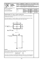
EXEMPLE DE CALCUL N°2 – POTEAU COMPRIMÉ-FLÉCHI MAINTENU LATÉRALEMENT<br />
CONSTITUÉ D’UNE SECTION SOUDÉE EN I<br />
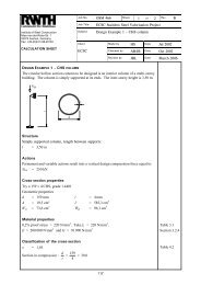
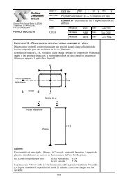
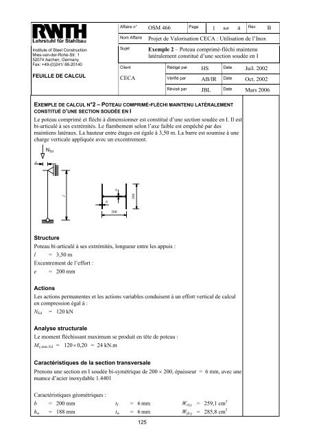
Le poteau comprimé et fléchi à dimensionner est constitué d’une section soudée en I. Il est<br />
bi-articulé à ses extrémités. Le flambement selon l’axe faible est empêché par <strong>de</strong>s<br />
maintiens latéraux. La hauteur entre étages est égale à 3,50 m. La barre est soumise à une<br />
charge verticale appliquée avec un excentrement.<br />
N Sd<br />
e<br />
6<br />
l<br />
6<br />
200<br />
200<br />
Structure<br />
Poteau bi-articulé à ses extrémités, longueur entre les appuis :<br />
l = 3,50 m<br />
Excentrement <strong>de</strong> l’effort :<br />
e = 200 mm<br />
Actions<br />
Les actions permanentes et les actions variables conduisent à un effort vertical <strong>de</strong> calcul<br />
en compression égal à :<br />
= 120 kN<br />
N Ed<br />
Analyse structurale<br />
Le moment fléchissant maximum se produit en tête <strong>de</strong> poteau :<br />
M y,max Ed = 120× 0, 20 = 24 kN.m<br />
Caractéristiques <strong>de</strong> la section transversale<br />
Prenons une section en I soudée bi-symétrique <strong>de</strong> 200 × 200, épaisseur = 6 mm, avec une<br />
nuance d’acier inoxydable 1.4401<br />
Caractéristiques géométriques :<br />
b = 200 mm t f = 6 mm W el,y = 259,1 cm 3<br />
h w = 188 mm t w = 6 mm W pl,y = 285,8 cm 3<br />
125
Affaire n° <strong>OSM</strong> <strong>466</strong> Page<br />
2 sur 4<br />
Rév B<br />
Institute of <strong>Steel</strong> Construction<br />
Mies-van-<strong>de</strong>r-Rohe-Str. 1<br />
52074 Aachen, Germany<br />
Fax: +49-(0)241/ 88-20140<br />
FEUILLE DE CALCUL<br />
Nom Affaire<br />
Sujet<br />
Client<br />
<strong>CECA</strong><br />
<strong>Projet</strong> <strong>de</strong> <strong>Valorisation</strong> <strong>CECA</strong> : Utilisation <strong>de</strong> l’Inox<br />
Exemple 2 – Poteau comprimé-fléchi maintenu<br />
latéralement constitué d’une section soudée en I<br />
Rédigé par HS Date Juil. 2002<br />
Vérifié par AB/IR Date Oct. 2002<br />
Révisé par JBL Date Mars 2006<br />
a = 3 mm (g<strong>org</strong>e du cordon <strong>de</strong> soudure) I y = 2591,1 cm 4<br />
A g = 35,3 cm² i y = 8,6 cm<br />
Caractéristiques du matériau<br />
Limite d’élasticité conventionnelle à 0,2% = 220 MPa. Prenons f y = 220 MPa Tableau 3.1<br />
E = 200 000 MPa et G = 76 900 MPa § 3.2.4<br />
Classification <strong>de</strong> la section transversale<br />
ε = 1,01 Tableau 4.2<br />
c 188 − 3 − 3<br />
Âme comprimée : =<br />
= 30, 3<br />
Tableau 4.2<br />
t 6<br />
c<br />
Limite <strong>de</strong> la Classe 3, ≤ 30,7ε<br />
, l’âme est donc (au moins) <strong>de</strong> Classe 3<br />
t<br />
c 200 / 2 − 6 / 2 − 3 94<br />
Tableau 4.2<br />
Semelle comprimée en console : =<br />
= = 15, 7<br />
t 6<br />
6<br />
c<br />
Limite <strong>de</strong> la Classe 3, ≤ 11,0ε<br />
, la partie <strong>de</strong> semelle en console est donc <strong>de</strong> Classe 4<br />
t<br />
Par conséquent, la section transversale est <strong>de</strong> Classe 4<br />
Caractéristiques <strong>de</strong> la section efficace<br />
Calcul du facteur <strong>de</strong> réduction ρ pour les parois soudées en console<br />
1 0,242<br />
ρ = − ≤ 1<br />
2<br />
Éq. 4.1c<br />
λ λ<br />
λ<br />
p<br />
p<br />
p<br />
b / t<br />
= où b = c = 94 mm Éq. 4.2<br />
28,4ε<br />
k<br />
σ<br />
En supposant une distribution uniforme <strong>de</strong> contrainte dans la semelle comprimée :<br />
σ 2<br />
ψ = = 1 Tableau 4.4<br />
σ<br />
1<br />
⇒ k σ = 0,43 Tableau 4.4<br />
94/ 6<br />
λ p =<br />
= 0,833<br />
28,4 × 1,01×<br />
0,43<br />
1 0,242 1 0,242<br />
ρ = − = − = 0, 852<br />
2 λ λ<br />
2<br />
0,833 0,833<br />
p<br />
p<br />
b eff = 0,852 × 94 Tableau 4.4<br />
= 80,1 mm<br />
126
Affaire n° <strong>OSM</strong> <strong>466</strong> Page<br />
3 sur 4<br />
Rév B<br />
Institute of <strong>Steel</strong> Construction<br />
Mies-van-<strong>de</strong>r-Rohe-Str. 1<br />
52074 Aachen, Germany<br />
Fax: +49-(0)241/ 88-20140<br />
FEUILLE DE CALCUL<br />
Nom Affaire<br />
Sujet<br />
Client<br />
<strong>CECA</strong><br />
<strong>Projet</strong> <strong>de</strong> <strong>Valorisation</strong> <strong>CECA</strong> : Utilisation <strong>de</strong> l’Inox<br />
Exemple 2 – Poteau comprimé-fléchi maintenu<br />
latéralement constitué d’une section soudée en I<br />
Rédigé par HS Date Juil. 2002<br />
Vérifié par AB/IR Date Oct. 2002<br />
Révisé par JBL Date Mars 2006<br />
Calcul <strong>de</strong> l’aire <strong>de</strong> la section transversale efficace pour la compression seule :<br />
−2<br />
A eff = − 4 × ( 1−<br />
ρ) ct<br />
= ( )<br />
A g<br />
35,3 − 4×<br />
1−<br />
0,852 × 94 × 6 × 10 = 31,9 cm 2<br />
Calcul <strong>de</strong> l'aire <strong>de</strong> la section transversale efficace pour la flexion seule selon l’axe fort :<br />
−2<br />
A eff = Ag − 2×<br />
( 1−<br />
ρ) ct<br />
= 35,3 2×<br />
( 1−<br />
0,852) × 94×<br />
6×<br />
10<br />
− = 33,6 cm 2<br />
Calcul du décalage <strong>de</strong> l’axe neutre à partir du calcul <strong>de</strong>s moments statiques <strong>de</strong> la section<br />
brute par rapport à son centre <strong>de</strong> gravité :<br />
z′ =<br />
2× (1 − ρ)<br />
c t × ( hw + tf<br />
)/<br />
2 2 × (1 − 0,852) × 94 × 6 × ( 188 + 6)<br />
/ 2<br />
=<br />
A<br />
2<br />
eff<br />
33,6 × 10<br />
= 4,8 mm <strong>de</strong> décalage dans la direction opposée à la semelle comprimée<br />
Calcul du moment d’inertie <strong>de</strong> la section efficace par rapport à l’axe fort :<br />
2<br />
⎡<br />
2<br />
t<br />
I y,eff = ( )<br />
( hw<br />
+ tf<br />
) ⎤<br />
2<br />
I y − 2×<br />
1−<br />
ρ ct × ⎢ + ⎥ − z′<br />
Aeff<br />
⎢⎣<br />
12 4 ⎥⎦<br />
et<br />
W eff,y =<br />
= 2591,1 − 2×<br />
( 1−<br />
0,852)<br />
= 2426,2 cm 4<br />
h<br />
w<br />
I<br />
/ 2<br />
y, eff<br />
t<br />
+ f<br />
+ z′<br />
=<br />
× 94×<br />
6×<br />
⎢ +<br />
⎢⎣<br />
12<br />
18,8 / 2<br />
2426,2<br />
2<br />
( 188 6) ⎤<br />
−4<br />
2<br />
−2<br />
⎡<br />
2<br />
6 +<br />
+ 0,6 + 0,48<br />
4<br />
⎥ × 10<br />
⎥⎦<br />
= 231,5 cm³<br />
− (4,8)<br />
× 33,6 × 10<br />
Résistance au flambement par flexion par rapport l’axe fort<br />
N b,Rd =<br />
χ A f γ<br />
Éq. 5.2b<br />
eff<br />
y<br />
M1<br />
A eff = 31,9 cm 2 pour une section transversale comprimée <strong>de</strong> Classe 4<br />
χ =<br />
≤ 1<br />
2 2 0,<br />
5<br />
ϕ + [ ϕ − λ ]<br />
2<br />
ϕ = 0,5<br />
( 1 α ( λ − λ ) + λ )<br />
λ =<br />
A<br />
eff<br />
N<br />
cr<br />
1<br />
0<br />
Éq. 5.3<br />
+ Éq. 5.4<br />
f<br />
y<br />
l = 350 cm (la longueur <strong>de</strong> flambement est égale à la longueur réelle)<br />
N cr =<br />
2<br />
π EI<br />
l<br />
2<br />
=<br />
π<br />
2<br />
× 200000 × 2591,1 × 10 −<br />
× 10<br />
2 2<br />
350 × 10<br />
4<br />
3<br />
= 4175,2 kN<br />
127
Affaire n° <strong>OSM</strong> <strong>466</strong> Page<br />
4 sur 4<br />
Rév B<br />
Institute of <strong>Steel</strong> Construction<br />
Mies-van-<strong>de</strong>r-Rohe-Str. 1<br />
52074 Aachen, Germany<br />
Fax: +49-(0)241/ 88-20140<br />
FEUILLE DE CALCUL<br />
Nom Affaire<br />
Sujet<br />
Client<br />
<strong>CECA</strong><br />
<strong>Projet</strong> <strong>de</strong> <strong>Valorisation</strong> <strong>CECA</strong> : Utilisation <strong>de</strong> l’Inox<br />
Exemple 2 – Poteau comprimé-fléchi maintenu<br />
latéralement constitué d’une section soudée en I<br />
Rédigé par HS Date Juil. 2002<br />
Vérifié par AB/IR Date Oct. 2002<br />
Révisé par JBL Date Mars 2006<br />
λ =<br />
31,9 × 10<br />
2<br />
4175,2 × 10<br />
× 220<br />
3<br />
= 0,410<br />
En utilisant le facteur d’imperfection α = 0,49 et l’élancement initial λ 0 = 0,2 pour les<br />
sections en I soudées<br />
2<br />
( 0,410 )<br />
ϕ = ,5 1 0,49( 0,410 − 0,2)<br />
χ =<br />
0 + + = 0,636<br />
0,636 +<br />
1<br />
2<br />
2<br />
[ 0,636 − 0,410 ] 0, 5<br />
= 0,891<br />
N b,y,Rd = 0,891 × 31,9 × 10 2 × 220 × 10 -3 / 1,1<br />
= 568,46 kN<br />
Tableau 5.1<br />
Résistance à la compression axiale et au moment uni-axial selon l’axe fort § 5.5.2<br />
N Ed<br />
M y,Ed + N Ed eNy<br />
+ k y ≤ 1<br />
Éq. 5.40<br />
N<br />
β W f γ<br />
( )<br />
b,Rd<br />
min<br />
W,y<br />
pl,y<br />
y / M1<br />
β W,y = W eff W pl, y pour une section transversale <strong>de</strong> Classe 4<br />
= 231 ,5/ 285, 8 = 0,810<br />
e Ny est nul en raison <strong>de</strong> la symétrie <strong>de</strong> la section transversale<br />
NEd<br />
120,0<br />
ky = 1,0 + 2( λ y − 0,5) = 1,0 + 2(0,410 − 0,5) = 0,962<br />
N<br />
568,46<br />
2N<br />
1,2 + N<br />
b,Rd.y<br />
b,Rd,y<br />
2 × 120<br />
= 1,2 +<br />
568,46<br />
Ed<br />
=<br />
mais 1,2<br />
≤ k y ≤1,<br />
62<br />
En conséquence, y =1, 2<br />
1,62<br />
k 6<br />
120,0<br />
24,0 × 10<br />
+ 1,2<br />
= 0,833 1<br />
3<br />
568,46 0,81×<br />
285,8 × 10 × 220/1,1<br />
La barre possè<strong>de</strong> donc une résistance satisfaisante.<br />
≤<br />
128