Stainless steel lattice girder made of hollow sections
Stainless steel lattice girder made of hollow sections
Stainless steel lattice girder made of hollow sections
- No tags were found...

Create successful ePaper yourself
Turn your PDF publications into a flip-book with our unique Google optimized e-Paper software.
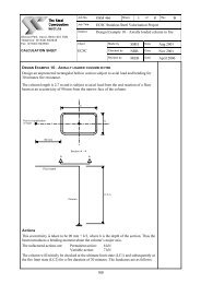
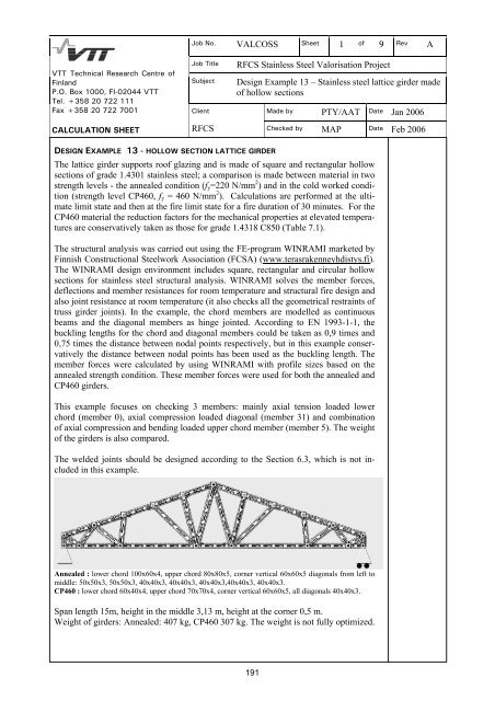
Job No. VALCOSS Sheet 1 <strong>of</strong> 9 Rev AVTT Technical Research Centre <strong>of</strong>FinlandP.O. Box 1000, FI-02044 VTTTel. +358 20 722 111Fax +358 20 722 7001Job TitleSubjectClientRFCS <strong>Stainless</strong> Steel Valorisation ProjectDesign Example 13 – <strong>Stainless</strong> <strong>steel</strong> <strong>lattice</strong> <strong>girder</strong> <strong>made</strong><strong>of</strong> <strong>hollow</strong> <strong>sections</strong>Made by PTY/AAT Date Jan 2006CALCULATION SHEETRFCS Checked by MAP Date Feb 2006DESIGN EXAMPLE 13 - HOLLOW SECTION LATTICE GIRDERThe <strong>lattice</strong> <strong>girder</strong> supports ro<strong>of</strong> glazing and is <strong>made</strong> <strong>of</strong> square and rectangular <strong>hollow</strong><strong>sections</strong> <strong>of</strong> grade 1.4301 stainless <strong>steel</strong>; a comparison is <strong>made</strong> between material in twostrength levels - the annealed condition (f y =220 N/mm 2 ) and in the cold worked condition(strength level CP460, f y = 460 N/mm 2 ). Calculations are performed at the ultimatelimit state and then at the fire limit state for a fire duration <strong>of</strong> 30 minutes. For theCP460 material the reduction factors for the mechanical properties at elevated temperaturesare conservatively taken as those for grade 1.4318 C850 (Table 7.1).The structural analysis was carried out using the FE-program WINRAMI marketed byFinnish Constructional Steelwork Association (FCSA) (www.terasrakenneyhdistys.fi).The WINRAMI design environment includes square, rectangular and circular <strong>hollow</strong><strong>sections</strong> for stainless <strong>steel</strong> structural analysis. WINRAMI solves the member forces,deflections and member resistances for room temperature and structural fire design andalso joint resistance at room temperature (it also checks all the geometrical restraints <strong>of</strong>truss <strong>girder</strong> joints). In the example, the chord members are modelled as continuousbeams and the diagonal members as hinge jointed. According to EN 1993-1-1, thebuckling lengths for the chord and diagonal members could be taken as 0,9 times and0,75 times the distance between nodal points respectively, but in this example conservativelythe distance between nodal points has been used as the buckling length. Themember forces were calculated by using WINRAMI with pr<strong>of</strong>ile sizes based on theannealed strength condition. These member forces were used for both the annealed andCP460 <strong>girder</strong>s.This example focuses on checking 3 members: mainly axial tension loaded lowerchord (member 0), axial compression loaded diagonal (member 31) and combination<strong>of</strong> axial compression and bending loaded upper chord member (member 5). The weight<strong>of</strong> the <strong>girder</strong>s is also compared.The welded joints should be designed according to the Section 6.3, which is not includedin this example.Annealed : lower chord 100x60x4, upper chord 80x80x5, corner vertical 60x60x5 diagonals from left tomiddle: 50x50x3, 50x50x3, 40x40x3, 40x40x3, 40x40x3,40x40x3, 40x40x3.CP460 : lower chord 60x40x4, upper chord 70x70x4, corner vertical 60x60x5, all diagonals 40x40x3.Span length 15m, height in the middle 3,13 m, height at the corner 0,5 m.Weight <strong>of</strong> <strong>girder</strong>s: Annealed: 407 kg, CP460 307 kg. The weight is not fully optimized.191
Job No. VALCOSS Sheet 2 <strong>of</strong> 9 Rev AVTT Technical Research Centre <strong>of</strong>FinlandP.O. Box 1000, FI-02044 VTTTel. +358 20 722 111Fax +358 20 722 7001Job TitleSubjectClientRFCS <strong>Stainless</strong> Steel Valorisation ProjectDesign Example 13 – <strong>Stainless</strong> <strong>steel</strong> <strong>lattice</strong> <strong>girder</strong> <strong>made</strong><strong>of</strong> <strong>hollow</strong> <strong>sections</strong>Made by PTY/AAT Date Jan 2006CALCULATION SHEETRFCS Checked by MAP Date Feb 2006ActionsAssuming the <strong>girder</strong> carries equally distributed snow load, glazing and its support structuresand weight <strong>of</strong> <strong>girder</strong> :Permanent actions (G): Load <strong>of</strong> glazing and supports 1 kN/m 2Dead load <strong>of</strong> <strong>girder</strong> (WINRAMI calculates the weight)Variable actions (Q): Snow load 2 kN/m 2Load case 1 to be considered (ultimate limit state): ∑ γLoad case 2 to be considered (fire situation):Ultimate limit state (room temperature design)γ G, j = 1,35 (unfavourable effects)γ Q,1 = 1,5j∑ γjG, j G k, j+ γ Q,1 Q k,1GA, j G k, j + k,1Fire designγ GA, j =1,0γ ψ1,1 = 0,2γψ1,1 Q(Recommended partial safety factors for actions shall be used in this example)Factored actions for ultimate limit state:Permanent action: Load on nodal points: 1,35 x 4,1 kNSelf weight <strong>of</strong> <strong>girder</strong> (is included by WINRAMI )Variable action Load from snow: 1,5 x 8,1 kNEq. 2.3EN 1990EN 1991-1-2Forces at critical member are:Forces are determined by the model using pr<strong>of</strong>iles in the annealed strength conditionLower chord member , member 0Annealed: 100x60x4 mm, CP460: 60x40x4 mmN t,Ed =142,2 kN,N t,fi,Ed = 46,9 kNM max ,Ed = 0,672 kNm, M max,fire,Ed =0,245 kNmUpper chord member, member 5Annealed: 80x80x5 mm, CP460: 70x70x4 mmN c,Ed = -149,1 kN,N c,fire,Ed = -49,2 kNM max ,Ed = 2,149 kNm, M max,fire,Ed = 0,731 kNmDiagonal member, member 31Annealed: 50x50x3mm,N c,Ed = -65,9 kN,CP460: 40x40x3 mmN c,fire,Ed = -21,7 kN192
Job No. VALCOSS Sheet 3 <strong>of</strong> 9 Rev AVTT Technical Research Centre <strong>of</strong>FinlandP.O. Box 1000, FI-02044 VTTTel. +358 20 722 111Fax +358 20 722 7001Job TitleSubjectClientRFCS <strong>Stainless</strong> Steel Valorisation ProjectDesign Example 13 – <strong>Stainless</strong> <strong>steel</strong> <strong>lattice</strong> <strong>girder</strong> <strong>made</strong><strong>of</strong> <strong>hollow</strong> <strong>sections</strong>Made by PTY/AAT Date Jan 2006CALCULATION SHEETRFCS Checked by MAP Date Feb 2006Material propertiesUse material grade 1.4301Annealed: f y = 220 N/mm 2 f u = 550 N/mm 2 E = 200 000 N/mm 2 Table 3.1CP460: f y = 460 N/mm 2 f u = 650 N/mm 2 E = 200 000 N/mm 2 Section 3.2.4Partial safety factors Table 2.1The following partial safety factors are used throughout the design example:γ M0 = 1,1, γ M1 = 1,1, γ M,fi = 1,0Cross section propertiesAnnealedMember 0: A= 1175 mm 2 W pl,y = 37,93·1000 mm 3Member 5: A=1436 mm 2 I y =131,44·10 4 mm 4 i y =30,3 mm W pl,y =39,74 ·10 3 mm 3Member 31: A=541 mm 2 I y =19,47·10 4 mm 4 i y = 19 mm W pl,y = 9,39·10 3 mm 3CP460Member 0: A= 695 mm W pl,y = 13,16·1000 mm 3Member 5: A=1015 mm 2 I y =72,12·10 4 mm 4 i y =26,7 mm W pl,y = 24,76·10 3 mm 3Classification <strong>of</strong> the cross-section <strong>of</strong> member 5 and member 31Annealed : ε =1,01 CP460 : ε =0,698 Table 4.2Assume conservatively that c = h − 2tAnnealed 80x80x5 : c = 80 − 10 = 70 mm CP460 70x70x4 : c = 70 – 8 = 62 mmAnnealed 50x50x3 : c = 50 – 6 = 44 mm CP460 40x40x3 : c = 40 – 6 = 34 mmFlange/web subject to compression: Table 4.2Annealed 80x80x5 : c/t = 14 CP460 70x70x4 : c/t = 15,5Annealed 50x50x3 : c/t = 14,6 CP460 40x40x3 : c/t = 11,3For Class 1,ct≤ 25, 7ε, therefore both pr<strong>of</strong>iles are classified as Class 1Member 31: A=421 mm 2 I y =9,32·10 4 mm 4 i y = 14,9 mm W pl,y = 5,72·10 3 mm 3LOWER CHORD MEMBER, DESIGN IN ROOM AND FIRE TEMPERATURE (Member 0)A) Room temperature designTension resistance <strong>of</strong> cross section Section 4.7.2N pl,Rd = Agf y γ Eq. 4.220MAnnealed : N pl,Rd = 1175 mm 2 ×220 N/mm 2 / 1,1 = 235 kN > 142,2 kN OK.CP460 : N pl,Rd = 695 mm 2 ×460 N/mm 2 / 1,1 = 290 kN > 142,2 kN OK.193
Job No. VALCOSS Sheet 4 <strong>of</strong> 9 Rev AVTT Technical Research Centre <strong>of</strong>FinlandP.O. Box 1000, FI-02044 VTTTel. +358 20 722 111Fax +358 20 722 7001Job TitleSubjectClientRFCS <strong>Stainless</strong> Steel Valorisation ProjectDesign Example 13 – <strong>Stainless</strong> <strong>steel</strong> <strong>lattice</strong> <strong>girder</strong> <strong>made</strong><strong>of</strong> <strong>hollow</strong> <strong>sections</strong>Made by PTY/AAT Date Jan 2006CALCULATION SHEETRFCS Checked by MAP Date Feb 2006Moment resistance <strong>of</strong> cross-section Sec. 4.7.4M c,Rd = Wplf y γ Eq. 4.270MAnnealed : M c,Rd =CP460 : M c,Rd =337,93×10 × 2201,1 × 1013,16 ⋅1031,1 ⋅1066⋅ 460= 7,58 kNm > 0,672 kNm OK.= 5,50 kNm > 0,672 kNm OK.Axial tension and bending moment interactionN M y,EdEq. 5.39Ed+ ≤ 1N MRdy,RdAnnealed :142,2 kN 0,672 kNm+ = 0,69 ≤1235 kN 7,58 kNmOK.CP460 :142,2 kN 0,672 kNm+ = 0,61 ≤ 1290 kN 5,50 kNmOK.B) Fire temperature designε res = 0,2Section 7.4.7Steel temperature after 30 min fire Θ = 823 °Cf 2,θ = f 0,2pro<strong>of</strong>,θ + g 2,θ (f u,θ – f 0,2pro<strong>of</strong>,θ ) Eq. 7.1Annealed :k 0,2 pro<strong>of</strong>,θ = 0,27-23/100×(0,27-0,14) = 0,240f 0,2pro<strong>of</strong>,θ = 0,240×220 N/mm 2 = 52,8 N/mm 2g 2,θ = (0,35 -23/100× (0,35 – 0,38) = 0,357f u,θ = ( 0,27- 23/100× (0,27-0,15)) ×550 N/mm 2 = 133,3 N/mm 2f 2,θ = 52,8 N/mm 2 + 0,357×(133,3 – 52,8) N/mm 2 = 81,5 N/mm 2k 2,θ = 81,5/220 = 0,37CP460 :k 0,2pro<strong>of</strong>,θ = 0,23-23/100× (0,23-0,11) = 0,202f 0,2pro<strong>of</strong>,θ = 0,202×460 N/mm 2 = 93,1 N/mm 2g 2,θ = 0,25f u,θ = ( 0,24 - 23/100× (0,24-0,10)) ×650 N/mm 2 = 135,1 N/mm 2f 2,θ = 93,1 N/mm 2 + 0,25×(135,1 – 93,1) N/mm 2 = 103,6 N/mm 2k 2,θ = 103,6 /460 = 0,225Section 7.2Table 7.1Eq. 7.1Section 7.2Table 7.1Eq. 7.1Tension resistance <strong>of</strong> cross sectionN fi,θ,Rd = k 2,θ N Rd [γ M0 / γ M,fi ] Eq. 7.6Annealed : N fi,θ,Rd = 0,370×235 kN×1,1/1,0 = 95,6 kN > 46,9 kN OK.CP460 : N fi,θ,Rd = 0,225×290 kN×1,1/1,0 = 59,3 kN > 46,9 kN OK.194
Job No. VALCOSS Sheet 5 <strong>of</strong> 9 Rev AVTT Technical Research Centre <strong>of</strong>FinlandP.O. Box 1000, FI-02044 VTTTel. +358 20 722 111Fax +358 20 722 7001Job TitleSubjectClientRFCS <strong>Stainless</strong> Steel Valorisation ProjectDesign Example 13 – <strong>Stainless</strong> <strong>steel</strong> <strong>lattice</strong> <strong>girder</strong> <strong>made</strong><strong>of</strong> <strong>hollow</strong> <strong>sections</strong>Made by PTY/AAT Date Jan 2006CALCULATION SHEETRFCS Checked by MAP Date Feb 2006Moment resistance <strong>of</strong> cross-sectionM fi,θ,Rd = k 2 , M Rd [ γ M 0 / γ M , fi ]θ Eq. 7.13Annealed : M fi,θ,Rd = 0,370 ×7,58 kNm ×1,1/1,0= 3,08 kNm > 0,245 kNm OK.CP460 : M fi,θ,Rd = 0,225 × 5,50 kNm ×1,1/1,0= 1,36 kNm > 0,245 kNm OK.Axial tension and bending moment interactionN MEd y,Ed+ ≤ 1N MRdy,Rd46,9 kN 0,245 kNmAnnealed : + = 0,57 ≤ 1 OK.95,6 kN 3,08 kNm46,9 kN 0,245 kNmCP460 : + = 0,97 ≤ 1 OK.59,3 kN 1,36 kNmEq. 5.39DIAGONAL MEMBER DESIGN IN ROOM AND FIRE TEMPERATURE (Member 31)Buckling length = 1253 mmA) Room temperature designN b,Rd = χ Af y / γ M 1Eq. 5.2aAnnealed :Lcr11253 1Eq. 5.5aλ = ( f y / E)= (220/ 200000)= 0,696i π19 π2ϕ = 0,5(1 + α(λ − λ 0 ) + λ ) = 0,5(1+0,49(0,696-0,4)+0,696 2 ) = 0,815Eq. 5.41χ ==2 2ϕ + ( ϕ − λ )0,815 +1(0,8152 −0,6962)= 0,807Eq. 5.3N b,Rd = 0,807×541 mm 2 ×220 N/mm 2 /1,1 = 87,3 kN > 65,9 kN OK.CP460 :Lcr11253 1λ = ( f y / E)= (460 / 200000)= 1,283i π14,9 π2ϕ = 0,5(1 + α(λ − λ0)+ λ ) = 0,5(1+0,49(1,283-0,4)+1,283 2 ) = 1,540Eq. 5.5aEq. 5.41χ ==2 2ϕ + ( ϕ − λ )1,540 +1(1,5402 −1,2832)= 0,418Eq. 5.3N b,Rd = 0,418×421 mm 2 ×460 N/mm 2 /1,1 = 73,6 kN > 65,9 kN OK.195
Job No. VALCOSS Sheet 6 <strong>of</strong> 9 Rev AVTT Technical Research Centre <strong>of</strong>FinlandP.O. Box 1000, FI-02044 VTTTel. +358 20 722 111Fax +358 20 722 7001Job TitleSubjectClientRFCS <strong>Stainless</strong> Steel Valorisation ProjectDesign Example 13 – <strong>Stainless</strong> <strong>steel</strong> <strong>lattice</strong> <strong>girder</strong> <strong>made</strong><strong>of</strong> <strong>hollow</strong> <strong>sections</strong>Made by PTY/AAT Date Jan 2006CALCULATION SHEETRFCS Checked by MAP Date Feb 2006B) Fire temperature designε res = 0,2Steel temperature after 30 min fire Θ= 832 °CAnnealed :k 0,2pro<strong>of</strong>,θ = 0,27-32/100×(0,27-0,14) = 0,228k E,θ = 0,63-32/100× (0,63-0,45) = 0,572CP460 :k 0,2pro<strong>of</strong>,θ = 0,23-32/100×(0,23-0,11) = 0,191k E,θ = 0,52-32/100×(0,52-0,35) = 0,465Section 7.4.7Section 7.2Table 7.1Section 7.2Table 7.1N b,fi,t,Rd = χ fi A k0 ,2 pro<strong>of</strong> , θ f y /γ M , fiEq. 7.8Annealed :λ θ = λ k / k ) = 0 ,696 (0,228/ 0,572)= 0,439 Eq. 7.12( 0,2pro<strong>of</strong> , θ E,θ20 θϕ = 0,5(1 + α(λ − λ ) + λ ) = 0,5(1+0,49(0,439-0,4)+0,439 2 ) = 0,606θθθθ1χ fi ==2 2ϕ + ( ϕ − λ ) 0,606 +θ1(0,6062 −= 0,97720,439 )N b,fi,t,Rd = 0,977×541 mm 2 ×0,228×220 N/mm 2 /1,0 = 26,5 kN > 21,7 kN OK.CP460 :Eq. 7.11Eq. 7.10λ θ = λ k / k ) = 1 ,283 (0,191/ 0,465)= 0,822 Eq. 7.12( 0,2pro<strong>of</strong> , θ E,θ20 θϕθ= 0,5(1 + α(λ − λ ) + λ ) = 0,5(1+0,49(0,822-0,4)+0,822 2 ) = 0,9411χfi==2 2ϕ + ( ϕ − λ ) 0,941+θθθθ1(0,9412 −= 0,71420,822 )N b,fi,t,Rd = 0,714×421 mm 2 ×0,191×460 N/mm 2 /1,0 = 26,4 kN > 21,7 kN OK.Eq. 7.11Eq. 7.10UPPER CHORD MEMBER DESIGN IN ROOM AND FIRE TEMPERATURE (Member 5)Buckling length = 1536 mmA) Room temperature designN ⎛ M y,Ed + N Ed eEd+ k ⎜yN , )b Rd min ⎝βW, yWpl,y f y / γNy( M1⎞Eq. 5.40⎟ ≤ 1,0⎠Annealed :β W,y = 1,0 class 1 cross section Sec. 5.5.2k y =1,0+2(λ y -0,5)N Ed /N b,Rd,y , but 1,2≤ k y ≤ 1,2+2N Ed /N b,Rd,yLcr11536 1λ = ( f y / E)= (220 / 200000)= 0,535i π30,3 πEq. 5.5a196
Job No. VALCOSS Sheet 7 <strong>of</strong> 9 Rev AVTT Technical Research Centre <strong>of</strong>FinlandP.O. Box 1000, FI-02044 VTTTel. +358 20 722 111Fax +358 20 722 7001Job TitleSubjectClientRFCS <strong>Stainless</strong> Steel Valorisation ProjectDesign Example 13 – <strong>Stainless</strong> <strong>steel</strong> <strong>lattice</strong> <strong>girder</strong> <strong>made</strong><strong>of</strong> <strong>hollow</strong> <strong>sections</strong>Made by PTY/AAT Date Jan 2006CALCULATION SHEETRFCS Checked by MAP Date Feb 20062ϕ = 0,5(1 + α(λ − λ 0 ) + λ ) = 0,5(1+0,49(0,535-0,4)+0,535 2 ) = 0,6761χ ==2 2ϕ + ( ϕ − λ ) 0,676 +1(0,6762 −Eq. 5.4= 0,917 Eq. 5.320,535 )N b,Rd,y = 0,917×1436 mm 2 ×220 N/mm 2 /1,1 = 263,3 kN > 149,1 kN Eq. 5.2ak y = 1,0+2(0,535-0,5) ×149,1/263,3 = 1,039 because calculated value is less than1,2, the value <strong>of</strong> k y = 1,2.2149,1 ⎛⎞⎜2,149 × 1000+ 1,2⎟= 0,890 < 1,0 OK.263,33Eq. 5.40⎝1,0× 39,74 × 10 × 220/1,1 ⎠CP460β W,y = 1,0 class 1 cross section Sec. 5.5.2Lcr11536 1Eq. 5.5aλ = ( f y / E)= (460 / 200000)= 0,878i π26,7 π2ϕ = 0,5(1 + α(λ − λ 0)+ λ ) = 0,5(1+0,49(0,878-0,4)+0,878 2 ) = 1,002Eq. 5.41χ ==2 2ϕ + ( ϕ − λ ) 1,002 +1(1,0022 −= 0,67320,878 )Eq. 5.3N b,Rd,y = 0,673×1015 mm 2 ×460 N/mm 2 /1,1 =285,6 kN > 149,1 kN Eq. 5.2ak y = 1,0+2(0,878-0,5)149,1/285,6 = 1,394, but 1,2 ≤ k y ≤ 1,2 + 2(149,1/285,6) =2,244, thus k y = 1,3942149,1 ⎛⎞⎜2,149×1000+ 1,394⎟= 0,81 < 1,0 OK.285,63Eq. 5.40⎝1,0× 24,76×10 × 460 /1,1 ⎠B) Fire temperature designε res = 0,2Steel temperature 80x80x5 mm Θ= 810 °CSteel temperature 70x70x4 mm Θ= 823 °CAnnealed :k 0,2pro<strong>of</strong>,θ = 0,27-10/100× (0,27-0,14) = 0,257f 0,2pro<strong>of</strong>,θ = 0,257×220 N/mm 2 = 56,5 N/mm 2g 2,θ = (0,35 -10/100× (0,35 – 0,38) = 0,353f u,θ = (0,27- 10/100× (0,27-0,15)) ×550 N/mm 2 = 141,9 N/mm 2f 2,θ = 56,5N/mm 2 + 0,353× (141,9 – 56,5) N/mm 2 = 86,6 N/mm 2k 2,θ = 86,6 /220 = 0,394k E,θ = 0,63 – 10/100× (0,63-0,45) = 0,612Section 7.4.7Section 7.2Table 7.1Eq. 7.1197
Job No. VALCOSS Sheet 8 <strong>of</strong> 9 Rev AVTT Technical Research Centre <strong>of</strong>FinlandP.O. Box 1000, FI-02044 VTTTel. +358 20 722 111Fax +358 20 722 7001Job TitleSubjectClientRFCS <strong>Stainless</strong> Steel Valorisation ProjectDesign Example 13 – <strong>Stainless</strong> <strong>steel</strong> <strong>lattice</strong> <strong>girder</strong> <strong>made</strong><strong>of</strong> <strong>hollow</strong> <strong>sections</strong>Made by PTY/AAT Date Jan 2006CALCULATION SHEETCP460 :k 0,2pro<strong>of</strong>,θ = 0,23-23/100× (0,23-0,11) = 0,202f 0,2pro<strong>of</strong>,θ = 0,202×460 N/mm 2 = 93,1 N/mm 2g 2,θ = 0,25f u,θ = (0,24- 23/100× (0,24-0,10)) ×650 N/mm 2 = 135,1N/mm 2f 2,θ = 93,1 N/mm 2 + 0,25× (135,1 – 93,1) N/mm 2 = 103,6 N/mm 2k 2,θ = 103,6 /460 = 0,225k E,θ = 0,52 – 23/100·(0,52-0,35) = 0,481RFCS Checked by MAP Date Feb 2006Section 7.2Table 7.2Eq. 7.1χmin, fiAgNkfi,Edy0,2 pro<strong>of</strong> , θγ M , fifk yM+My,fi,Edy,fi,θ , Rd≤1,0Eq. 7.24Annealed :λ θ = λ ( k 0,2pro<strong>of</strong> , θ / k E,θ ) = 0 ,535 (0,257 / 0,612)= 0,347 Eq. 7.122ϕ θ = 0,5(1 + α(λθ− λ 0 ) + λθ) = 0,5(1+0,49(0,347-0,4)+0,347 2 ) = 0,547χ1fi ==2 2ϕθ+ ( ϕθ− λθ)0,547 +1(0,5472 −= 1,03 = 1,020,347 )Eq. 7.11Eq. 7.10µ y N fi,Edk y = 1 −≤ 3Eq. 7.28χ A k f / γy,fig0,2 pro<strong>of</strong> , θyM , fiEq. 7.29µ 1,2β− 3) λ θ + 0,44β− 0,29 0,8y = ( M , y y,M , y ≤χmin,fi A gk0,2pro<strong>of</strong> , f y / γ =1,0×1436 mm 2 ×0,257×220 N/mm 2 /1,0= 81,2 kNθ M , fiEq. 7.8> 49,2 kN OK.M y,fi,θ,Rd = k 2,θ [γ M0/ γ M,fi ]M Rd = 0,394 ×1,1/1,0×39,74×10 3 ×220/1000 2 = 3,79 kNm Eq. 7.13>0,731 kNm OK.ψ = -0,487 kNm/0,731 kNm = -0,666Table 7.3β M,y = 1,8-0,7×ψ = 2,466µ y = (1,2×2,466-3)0,347 + 0,44×2,466 – 0,29 = 0,78,Eq. 7.29because calculated value is less than 0,8, the value <strong>of</strong> µ y = 0,8k y = 1- 0,80×49,2 kN/81,2 kN = 0,515 Eq. 7.2849,2 0,731+ 0,515×= 0,70 < 1,081,2 3,79OK. Eq. 7.24CP460 :λ θ = λ ( k 0,2pro<strong>of</strong> , θ / k E,θ ) = 0 ,878 (0,202 / 0,481)= 0,569 Eq. 7.1220 θϕ = 0,5(1 + α(λ − λ ) + λ ) = 0,5(1+0,49(0,569-0,4)+0,569 2 ) = 0,703θθ1χ fi ==2 2ϕ + ( ϕ − λ ) 0,703 +θθθ1(0,7032 −= 0,89620,569 )Eq. 7.11Eq. 7.10198
Job No. VALCOSS Sheet 9 <strong>of</strong> 9 Rev AVTT Technical Research Centre <strong>of</strong>FinlandP.O. Box 1000, FI-02044 VTTTel. +358 20 722 111Fax +358 20 722 7001Job TitleSubjectClientRFCS <strong>Stainless</strong> Steel Valorisation ProjectDesign Example 13 – <strong>Stainless</strong> <strong>steel</strong> <strong>lattice</strong> <strong>girder</strong> <strong>made</strong><strong>of</strong> <strong>hollow</strong> <strong>sections</strong>Made by PTY/AAT Date Jan 2006CALCULATION SHEETRFCS Checked by MAP Date Feb 2006χmin,fi A gk0,2pro<strong>of</strong> , f y / γ =0,896×1015 mm 2 ×0,202×460 N/mm 2 /1,0=84,5 kN Eq. 7.8θ M , fi>49,2 kN OK.M y,fi,θ,Rd = k 2,θ [γ M0/ γ M,fi ]M Rd = 0,225×1,1/1,0×24,76×10 3 ×460/1000 2 = 2,81 kNm Eq. 7.13>0,731 kNm OK.ψ = -0,487 kNm/0,731 kNm = -0,666Table 7.3β M,y = 1,8-0,7×ψ = 2,466µ y = (1,2×2,466-3)0,569 + 0,44×2,466 – 0,29 = 0,771,Eq. 7.29because calculated value is less than 0,8, the value <strong>of</strong> µ y = 0,8k y = 1- 0,80 × 49,2 kN/84,5 kN = 0,534 Eq. 7.2849,2 0,731+ 0,534×= 0,72 < 1,0 OK. Eq. 7.2484,5 2,81199