Design Example 5 Welded joint - Steel-stainless.org
Design Example 5 Welded joint - Steel-stainless.org
Design Example 5 Welded joint - Steel-stainless.org

Create successful ePaper yourself
Turn your PDF publications into a flip-book with our unique Google optimized e-Paper software.
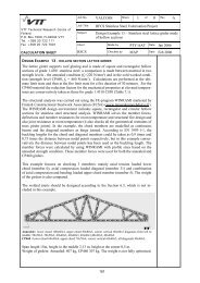
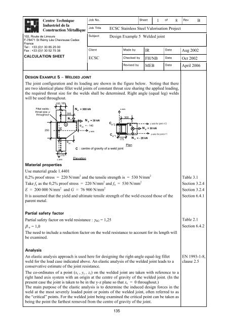
Job No. Sheet 1 of 8 Rev B102, Route de LimoursF-78471 St Rémy Lès Chevreuse CedexFranceTel : +33 (0)1 30 85 25 00Fax : +33 (0)1 30 52 75 38CALCULATION SHEETJob TitleSubjectClientECSCECSC Stainless <strong>Steel</strong> Valorisation Project<strong>Design</strong> <strong>Example</strong> 5 <strong>Welded</strong> <strong>joint</strong>Made by IR Date Aug 2002Checked by FH/NB Date Oct 2002Revised by MEB Date April 2006DESIGN EXAMPLE 5 – WELDED JOINTThe <strong>joint</strong> configuration and its loading are shown in the figure below. Noting that thereare two identical plane fillet weld <strong>joint</strong>s of constant throat size sharing the applied loading,the required throat size for the welds shall be determined. Right angle (equal leg) weldswill be used throughout.Fillet welds :throat size athroughout250100 100C175z axisa300N xe ycN z = 300 kNN y = 30 kNe zc = - 140Elevationy axisC n°2Cn°1x axis175C : centre of gravity of a weld <strong>joint</strong>300N zPlanN x = - 20 kNy axis for <strong>joint</strong> n°2N y = 30 kNy axis for <strong>joint</strong> n°1Material propertiesUse material grade 1.44010,2% proof stress = 220 N/mm 2 and the tensile strength is = 530 N/mm 2 Table 3.1Take f y as the 0,2% proof stress = 220 N/mm 2 and f u = 530 N/mm 2 Section 3.2.4E = 200 000 N/mm 2 and G = 76 900 N/mm 2 Section 3.2.4It is assumed that the yield and ultimate tensile strength of the weld exceed those of the Section 6.4.1parent metal.Partial safety factorPartial safety factor on weld resistance : γ M2 = 1,25 Table 2.1β w = 1,0 Section 6.4.2The need to include a reduction factor on the weld resistance to account for its length willbe examined.AnalysisAn elastic analysis approach is used here for designing the right-angle equal-leg filletweld for the load case indicated above. An elastic analysis of the welded <strong>joint</strong> leads to aconservative estimate of the <strong>joint</strong> resistance.The co-ordinates of a point (x c , y c , z c ) on the welded <strong>joint</strong> are taken with reference to aright hand axis system with an origin at the centre of gravity of the welded <strong>joint</strong>. (In thepresent case the <strong>joint</strong> is taken to be in the y-z plane so that x c = 0 throughout.)The main purpose of the elastic analysis is to determine the induced design forces in theweld at the most severely loaded point or points of the welded <strong>joint</strong>, often referred to asthe “critical” points. For the welded <strong>joint</strong> being examined the critical point can be taken asbeing the point the farthest removed from the centre of gravity of the <strong>joint</strong>.EN 1993-1-8,clause 2.5135
Job No. Sheet 2 of 8 Rev B102, Route de LimoursF-78471 St Rémy Lès Chevreuse CedexFranceTel : +33 (0)1 30 85 25 00Fax : +33 (0)1 30 52 75 38CALCULATION SHEETJob TitleSubjectClientECSCECSC Stainless <strong>Steel</strong> Valorisation Project<strong>Design</strong> <strong>Example</strong> 5 <strong>Welded</strong> <strong>joint</strong>Made by IR Date Aug 2002Checked by FH/NB Date Oct 2002Revised by MEB Date April 2006The vectors of the applied force, its eccentricity and the resulting moments acting on awelded <strong>joint</strong> of general form and centre of gravity C can be expressed as follows :Applied forceN =[ N , N N ]w, Edx,Ed y,Ed,Eccentricity of the applied force[ e , e e ]N xc yc,zcz,Ede = which are the co-ordinates of the point of application of theforce vectorN w, EdApplied momentsM xc, Ed = eycNM yc, Ed = ezcNM = e Nzc, Edxcz,Edx,Edy,Ed− e− e− ezcxcycNNNy,Edz,Edx,EdA linear elastic analysis of the <strong>joint</strong> for a general load case leads to the following inducedforce components per unit length of weld at a point with co-ordinates (x c , y c , , z c ) , wherethe throat size is denoted by a:F wx,Ed =⎡ Na ⎢⎢⎣Ax,EdwzcM+Iyc,EdycycM−Izc,Ed⎡ Ny,Edx⎤F wy,Ed =cMzc,EdzcMxc,Eda ⎢ + − ⎥⎣ AwIzcIxc⎦F wz,Ed =⎡ Na ⎢⎢⎣Az,EdwycM+Ixc,EdxcxcM−Izcyc,Edyc⎤⎥⎥⎦⎤⎥⎥⎦In the above expressions, the resisting sectional throat area and the inertias about theprincipal axes of the welded <strong>joint</strong> are:A w = a dl =∑a i lifor a weld of straight segments of length l∫ i and throat size a i ,∫∫∫2c +2cI xc = a ( y z ) dl2c +2cI yc = a ( x z ) dl2c +2cI zc = a ( x y ) dlAs the throat size, a, is constant throughout the plane <strong>joint</strong>, one can write :Aw= dl =∫ ∑li,aSince x c = 0,136
Job No. Sheet 3 of 8 Rev B102, Route de LimoursF-78471 St Rémy Lès Chevreuse CedexFranceTel : +33 (0)1 30 85 25 00Fax : +33 (0)1 30 52 75 38CALCULATION SHEETJob TitleSubjectClientECSCECSC Stainless <strong>Steel</strong> Valorisation Project<strong>Design</strong> <strong>Example</strong> 5 <strong>Welded</strong> <strong>joint</strong>Made by IR Date Aug 2002Checked by FH/NB Date Oct 2002Revised by MEB Date April 2006IazcI( y2 yc= ∫ c) dl , = ( z2 c) dla∫,IaxcI2 2yc I= ∫ ( yc+ zc) dl = +a a<strong>Design</strong> approaches Section 6.4.2Determine the required weld throat size at the critical point.Two different procedures are allowed for designing fillet welds:The first procedure is based on the simplified, and more conservative, design shearstrength for a fillet weld. The design shear force per unit length of weld at any point of the<strong>joint</strong> is defined as the vector sum of the induced forces per unit length due to all forcesand moments transmitted by the welded <strong>joint</strong>. This design shear force per unit lengthshould not exceed the design resistance per unit length which is taken as the design shearstrength multiplied by the throat size. This approach ignores the throat plane orientation tothe direction of resultant weld force per unit length.The second procedure is based on comparing the basic design strength of the weaker partjoined to the applied design weld stress in the weld throat determined by a Von Mises typeof formula. This approach is the most precise as it allows for the throat plane orientationto the direction of resultant weld force per unit length.zc1. Simplified design shear strength of the weldThe design resistance check of the fillet weld is as follows:⎛ ⎞2 2 2fF w,Ed =⎜u / 3EN 1993-1-8,F + + ≤ = = ⎟wx,Ed Fwy,EdFwz,EdFw,Rdaf vw,d aclause 4.5.3.3⎝ β wγM2 ⎠Where:f vw,d is the design shear strength of the weldF w,Rd is the design (shear) resistance per unit length of weld of throat size a.For <strong>stainless</strong> steel β w may be take as 1.0 Section 6.4.2When the design procedure requires that a suitable throat size be obtained, the designexpression becomes :F w,Eda ≥fvw,d2. Basic design strength of the weldIn this approach one must check the Von Mises type stress in the weld throat against thebasic design strength of the fillet weld material. In general this requires that the stresses inthe weld throat, σ ⊥ , τ ⊥ and τ ⎥⎥ be obtained, thus taking account of the orientation of theplane of the throat area to the direction of the resultant induced weld force per unit length.The design formula is as follows:2 2 2 f uEq. 6.12aσ ⊥ + 3( τ ⊥ + τ ) ≤⎥⎥β γwM2It is also required to check the normal stress separately:0.9f uσ ⊥ ≤γM2137Eq 6.12b
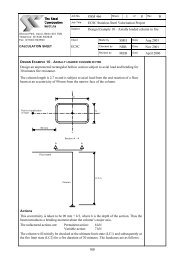
Job No. Sheet 4 of 8 Rev B102, Route de LimoursF-78471 St Rémy Lès Chevreuse CedexFranceTel : +33 (0)1 30 85 25 00Fax : +33 (0)1 30 52 75 38CALCULATION SHEETJob TitleSubjectClientECSCECSC Stainless <strong>Steel</strong> Valorisation Project<strong>Design</strong> <strong>Example</strong> 5 <strong>Welded</strong> <strong>joint</strong>Made by IR Date Aug 2002Checked by FH/NB Date Oct 2002Revised by MEB Date April 2006For the present case of a plane fillet weld <strong>joint</strong> with right angle (equal leg) welds this lattercheck is not critical. However it may be so for partial penetration welds in bevelled <strong>joint</strong>s.Instead of having to calculate the stresses (σ ⊥ , τ ⊥ and τ ⎥⎥ ) in the weld throat the followingdesign check expression may be used for y-z plane <strong>joint</strong>s with right angle (equal leg)welds:2F2w, x+ 2F+ 2Fw,yFw,z2w, y+ 2F2w, z+ F2w, y⎛ fSinθCosθ≤ ⎜au⎝ βwγ2Cos θ +M22F w, z2⎞⎟⎠2Sin θ − 2FNote : The subscripts have been shortened: F w,x for F wx,Ed etc.w,xFw,ySinθ+ 2Fw,xFw,zCosθIn the above expression the angle θ is that between the y axis and the axis of the weld asshown in the following figure.attachedelementSection 1-1F w,xsupportattachedelement11F w,zzF w,yθyattachedelementFillet weld axis2θF w,zz2F w,yyF w,xattachedelementsupportSection 2-2The force components at the critical point of the weld are determined in theAppendix to this design example.1. <strong>Design</strong> using the simplified design shear strength approachThe design shear strength for the simplified design approach is:f u530f vw,d = =≈ 245N/mm 2 EN 1993-1-8,γ 3 1.0 × 1,25×3Eq. 4.4β wM2The value of the resultant induced force per unit length in a weld throat of 1mm is :2 2 2 2 2 2wx, Ed wy, Ed wz, Ed=F w,Ed = F + F + F = 243 + 747 + 966 1245 N/mmThe required throat size is therefore:Fw,Ed1245a ≥ = ≈ 5, 0 mmf 245vw,d138
Job No. Sheet 5 of 8 Rev B102, Route de LimoursF-78471 St Rémy Lès Chevreuse CedexFranceTel : +33 (0)1 30 85 25 00Fax : +33 (0)1 30 52 75 38CALCULATION SHEETJob TitleSubjectClientECSCECSC Stainless <strong>Steel</strong> Valorisation Project<strong>Design</strong> <strong>Example</strong> 5 <strong>Welded</strong> <strong>joint</strong>Made by IR Date Aug 2002Checked by FH/NB Date Oct 2002Revised by MEB Date April 20062. <strong>Design</strong> of the weld using the basic design weld strength approachThe basic design strength of the weld material is taken as follows:0.9 fγM2u0.9×530= = 381, 6 N/mm 2 Eq. 6.12b1,25Where f u is the ultimate tensile strength of the weaker part joinedAt the point (a), where the angle θ is 0°, the design check expression becomes:2F2 2 2wx, Ed + 3Fwy, Ed + 2Fwz, Ed + 2The required throat size is therefore:Fwx,EdFwz,Ed≤⎛ f⎜a⎝ γuMw⎞⎟⎠2222 × ( −243 ) + 3 × (747 ) + 2 × (966 ) + 2 × ( −243 ) × (966 )a ≥ = 4,7381,6Adopt a 5 mm throat size and assume that the weld is full size over its entire length.2mmNote :A reduction factor is required for splice <strong>joint</strong>s when the effective length of fillet weld isgreater than 150a. The reduction factor would seem to be less relevant for the presenttype of <strong>joint</strong>. Nevertheless by considering, safely, the full length of the welded <strong>joint</strong> and athroat size of 5 mm one obtains:β LW.1 = 1,2− 0,2L j /(150a)= 1,2 − 0,2(600) /(150×5) = 1, 04 Take β LW.1 = 1,0It is concluded that the use of a reduction factor on the design strength of the weld is notrequired.EN 1993-1-8,Eq. 4.9139
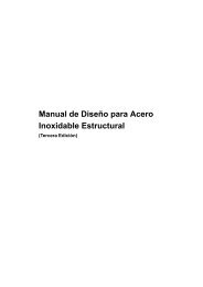
Job No. Sheet 6 of 8 Rev B102, Route de LimoursF-78471 St Rémy Lès Chevreuse CedexFranceTel : +33 (0)1 30 85 25 00Fax : +33 (0)1 30 52 75 38CALCULATION SHEETJob TitleSubjectClientECSCECSC Stainless <strong>Steel</strong> Valorisation Project<strong>Design</strong> <strong>Example</strong> 5 <strong>Welded</strong> <strong>joint</strong>Made by IR Date Aug 2002Checked by FH/NB Date Oct 2002Revised by MEB Date April 2006Appendix – Calculation of the force components at the critical point of the weldGeometric properties of the welded <strong>joint</strong>There are two similar <strong>joint</strong>s, one on each side of the column, resisting the applied loads.Only one of the <strong>joint</strong>s needs to be examined. It is placed in the y-z plane.Throat area and positions of the centre of gravity and the critical pointThroat area (resisting section) of each of the <strong>joint</strong>s made up of straight segments of lengthL i and constant throat size a is, for each 1mm of throat size:∫∑∑A a ds Awa= w, i aLw,i= = =∑Li= (2×175 + 250) =a a a600 mm 2 /mDistance of the centre of gravity from the vertical side (parallel to the z axis) of the <strong>joint</strong>of constant throat size a:∑yi( Aw,i / a)∑yiLi2×(87,5×175) + (0×250)y = = =≈ 51mmA / a L600∑w, i∑i51y ca = +175 - 51 = +124e ycLoad point125r c,aae zcz ca = -125Cy-y125d175z-zThe co-ordinates of the position of the critical point of the <strong>joint</strong>, the point (a), relative tothe principal axes through centre of gravity (C) are :y ca = + ( 175 − 51) = + 124 mm z ca = −125 mmNote: the point (d) might also be chosen as a potential critical point, for which :y cd = + ( 175 − 51) = + 124 mm z cd = +125 mmHowever, for the load case considered it is evident that the point (a) is the most critical.Inertias of the <strong>joint</strong> resisting sectionFor each of the <strong>joint</strong>s, for each 1mm of throat size :I yc=a2∫ z ds23c = 2 × 175×125 + 250 /12 = 6,77×10 mm4 /mm6140
Job No. Sheet 7 of 8 Rev B102, Route de LimoursF-78471 St Rémy Lès Chevreuse CedexFranceTel : +33 (0)1 30 85 25 00Fax : +33 (0)1 30 52 75 38CALCULATION SHEETJob TitleSubjectClientECSCECSC Stainless <strong>Steel</strong> Valorisation Project<strong>Design</strong> <strong>Example</strong> 5 <strong>Welded</strong> <strong>joint</strong>Made by IR Date Aug 2002Checked by FH/NB Date Oct 2002Revised by MEB Date April 2006I zc=a22 32c = 250×51 + 2×175 /12 + 2×175×(87,5 − 51)∫ y ds= 210 mm4 /mmFor the “torsion” moment the relevant inertia, per <strong>joint</strong>, is :I xc = a r ds∫22c = a∫ y ds a∫2c+ zcds = I zc + I ycSo thatI xc=a6( 6,77 + 2,01) × 10 = 8,78×10 mm 4 /mm6Applied forces and momentsIt is assumed that applied loads and moments are shared equally by the two <strong>joint</strong>s.The applied axial and shear force components per <strong>joint</strong> are:N x, Ed =2030− = − 10 kN, N y, Ed = +22= + 15 kN,N z, Ed =300+2= + 150 kNApplied moments are calculated using the applied force components and theireccentricities. The eccentricities, i.e. the co-ordinates of the effective load point, are :e xc = 0 as the effective load point is taken to be in the y-z plane of the <strong>joint</strong>,e yc = (300 − 100 + 175 − 51) = +324 mm,e zc = −140 mmThe applied moments, per <strong>joint</strong>, are then;M xc,Ed = eyc N z,Ed − ezcN y,Ed = ( + 324) × ( + 150) − ( −140)× ( + 15) = + 50, 7 kNmM yc,Ed = ezc N x,Ed − excN z,Ed = ( −140)× ( −10)− (0) × ( + 150) = + 1, 4 kNmM zc,Ed = e N − e N = (0) × ( + 15) − ( + 324) × ( −10)= 3, 24 kNmxc y,Ed yc x,Ed+Force components at the critical point of the weldFor the y-z plane <strong>joint</strong>, the force components per unit length of weld at the point (a) are:F wx,Ed =F wy,Ed =F wz,Ed =NANANAzMyMx,Ed ca yc,Ed ca zc,Ed+−w / a I yc / a I zc / azcaM−a I / aycaM+a I / ay,Edxc,Edw / xczc,Edxc,Edw / xc141
Job No. Sheet 8 of 8 Rev B102, Route de LimoursF-78471 St Rémy Lès Chevreuse CedexFranceTel : +33 (0)1 30 85 25 00Fax : +33 (0)1 30 52 75 38CALCULATION SHEETJob TitleSubjectClientECSCECSC Stainless <strong>Steel</strong> Valorisation Project<strong>Design</strong> <strong>Example</strong> 5 <strong>Welded</strong> <strong>joint</strong>Made by IR Date Aug 2002Checked by FH/NB Date Oct 2002Revised by MEB Date April 2006The contributions to the weld force components (at all points of the welded <strong>joint</strong>) from theapplied force components are :NNx,Ed − 10F w, x = = = − 0, 017 kN/mmAw/ a 600N yN y,Ed + 15F w,y = = = + 0, 025 kN/mmAw/ a 600NNz,Ed + 150F w, z = = = + 0, 25 kN/mmA / a 600wThe various contributions to the weld force components per unit length of weld at thepoint (a) from the applied moment components are :MFxc w, y = − Mxc, Edzc,a6 ( −125)= − 50,7 × 10 ×( I / )6xc a8,78 × 10= + 722 N/mmMFxc w, z = + Mxc, Edyc,a6 ( + 124)= + 50,7 × 10 ×( I / )6xc a8,78 × 10= + 716 N/mmM yczc,a6 ( −125)F w,x = + M yc, Ed = + 1,41 × 10 ×( I / )6yc a6,77 × 10= − 26 N/mmMFzc w, x = − Mzc,Edyc,a6 ( + 124)= − 3,24 × 10 ×( I / )6zc a2,01 × 10= − 200 N/mmCombining the contributions at the point (a) from the forces and the moments oneobtains :F wx,Ed =F wy,Ed =F wz,Ed =N Myc Mzcw, x Fw,xF w, xN y M xcw, y F w, yN M xcw, z F w, zF + + = −17 −26 −200 = −243 N/mmF + = +25 +722 = +747 N/mmF + = +250 +716 = +966 N/mmThese resultant induced force components per unit length are for a welded <strong>joint</strong> with aweld throat size of 1mm throughout its entire effective length.142