Fire resistance of RHS beam-column - Steel-stainless.org
Fire resistance of RHS beam-column - Steel-stainless.org
Fire resistance of RHS beam-column - Steel-stainless.org

Create successful ePaper yourself
Turn your PDF publications into a flip-book with our unique Google optimized e-Paper software.
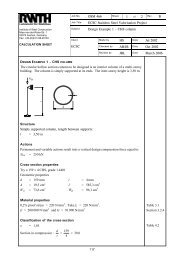
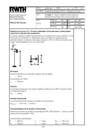
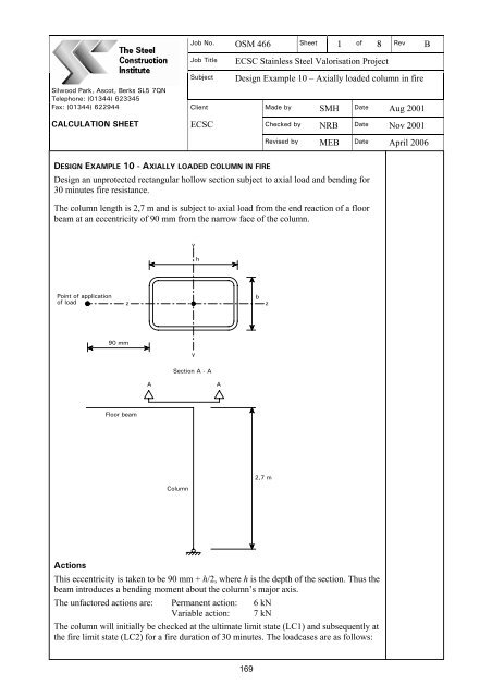
Job No. OSM 466 Sheet 1 <strong>of</strong> 8 Rev BSilwood Park, Ascot, Berks SL5 7QNTelephone: (01344) 623345Fax: (01344) 622944CALCULATION SHEETJob TitleSubjectClientECSCECSC Stainless <strong>Steel</strong> Valorisation ProjectDesign Example 10 – Axially loaded <strong>column</strong> in fireMade by SMH Date Aug 2001Checked by NRB Date Nov 2001Revised by MEB Date April 2006DESIGN EXAMPLE 10 - AXIALLY LOADED COLUMN IN FIREDesign an unprotected rectangular hollow section subject to axial load and bending for30 minutes fire <strong>resistance</strong>.The <strong>column</strong> length is 2,7 m and is subject to axial load from the end reaction <strong>of</strong> a floor<strong>beam</strong> at an eccentricity <strong>of</strong> 90 mm from the narrow face <strong>of</strong> the <strong>column</strong>.yhPoint <strong>of</strong> application<strong>of</strong> loadzbz90 mmySection A - AAAFloor <strong>beam</strong>2,7 mColumnActionsThis eccentricity is taken to be 90 mm + h/2, where h is the depth <strong>of</strong> the section. Thus the<strong>beam</strong> introduces a bending moment about the <strong>column</strong>’s major axis.The unfactored actions are: Permanent action: 6 kNVariable action: 7 kNThe <strong>column</strong> will initially be checked at the ultimate limit state (LC1) and subsequently atthe fire limit state (LC2) for a fire duration <strong>of</strong> 30 minutes. The loadcases are as follows:169
Job No. OSM 466 Sheet 2 <strong>of</strong> 8 Rev BSilwood Park, Ascot, Berks SL5 7QNTelephone: (01344) 623345Fax: (01344) 622944CALCULATION SHEETJob TitleSubjectClientECSCECSC Stainless <strong>Steel</strong> Valorisation ProjectDesign Example 10 – Axially loaded <strong>column</strong> in fireMade by SMH Date Aug 2001Checked by NRB Date Nov 2001Revised by MEB Date April 2006LC1 (ultimate limit state)∑jγ G, j = 1,35 (unfavourable effects)γ Q,1 = 1,5γ + γ Q,1 QEqn. 2.3k,1G, j G k,LC2 (fire limit state)∑γ + ψjGA, jGk,j 1,1Qk,1γGA= 1,0Values for ψ 1, 1 are given in EN 1990 and NA for EN 1990, but for this exampleconservatively assume ψ 1, 1 = 1,0jSection 2.3.2Design at the Ultimate Limit State (LC1)Loading on the corner <strong>column</strong> due to shear force at end <strong>of</strong> <strong>beam</strong> (LC1):Axial force N Ed = 1,35 × 6 +1,5 × 7 = 18,6 kNTry 100 × 50 × 6 Rectangular Hollow SectionMajor axis bending moment (due to eccentricity <strong>of</strong> shear force from centroid <strong>of</strong> <strong>column</strong>),M y,Ed = 18,6 × (0,09+0,10/2) = 2,60 kNmMaterial propertiesUse material grade 1.44010,2% pro<strong>of</strong> stress = 220 N/mm 2 and f u = 530 N/mm 2 Table 3.1Take f y as the 0,2% pro<strong>of</strong> stress = 220 N/mm 2 Section 3.2.4E = 200 000 N/mm 2 and G = 76 900 N/mm 2 Section 3.2.4Cross-section properties – 100 x 50 x 6 mm <strong>RHS</strong>W el,y = 32,58 × 10 3 mm 3 i y = 32,9 mmW pl,y = 43,75 × 10 3 mm 3 i z = 19,1 mmA g = 1500 mm 2 t = 6 mmClassification <strong>of</strong> the cross-sectionε = 1,01 Table 4.2Assume conservatively that c = h − 2t = 100 − 12 = 88 mm for webWebs subject to compression:For Class 1,ct≤25,7εct=886= 14,7= 25,96 ∴ Web is Class 1Table 4.2170
Job No. OSM 466 Sheet 3 <strong>of</strong> 8 Rev BSilwood Park, Ascot, Berks SL5 7QNTelephone: (01344) 623345Fax: (01344) 622944CALCULATION SHEETJob TitleSubjectClientECSCECSC Stainless <strong>Steel</strong> Valorisation ProjectDesign Example 10 – Axially loaded <strong>column</strong> in fireMade by SMH Date Aug 2001Checked by NRB Date Nov 2001Revised by MEB Date April 2006By inspection, if the web is Class 1 subject to compression, then the flange will also beClass 1. ∴ Cross-section is Class 1Partial safety factorsThe following partial safety factors are used throughout the design example for LC1: Table 2.1γ M0 = 1,1γ M1 = 1,1Buckling <strong>resistance</strong> to axial compression Section 5.3.3Resistance to flexural buckling about the z-z axis:χ z AgfyEq. 5.2aN b,z,Rd = For Class 1, 2 and 3 cross-sectionsγM 1χ = reduction factor to account for buckling =2ϕ = 0,5( 1 α ( λ − λ ) + λ )λ z =L crλ z =Licrz1π012 2[ ϕ − ]ϕ + λ0,5≤1Eq. 5.3+ Eq. 5.4f yE= buckling length <strong>of</strong> <strong>column</strong>, taken conservatively as 1,0 × <strong>column</strong> length = 2,7 m2700 119,1 π220200000= 1,492Eq. 5.5aFor hollow sections subject to flexural buckling, α = 0,49 and λ 0 = 0,40 Table 5.12( 1,492 )ϕ = ,5 1 0,49( 1,492 − 0,4)χ z =0 + + = 1,8811,881 +12 2[ 1,881 −1,492]0,5≤ 1χ z = 0,33050 ,3305×1500×220N b,z,Rd == 99,15 kN1,1(Resistance to torsional buckling will not be critical for a rectangular hollow section witha h/b ratio <strong>of</strong> 2.)= 18,6 kN Buckling <strong>resistance</strong> <strong>of</strong> cross-section is OKN EdSection 5.3.1171
Job No. OSM 466 Sheet 4 <strong>of</strong> 8 Rev BSilwood Park, Ascot, Berks SL5 7QNTelephone: (01344) 623345Fax: (01344) 622944CALCULATION SHEETJob TitleSubjectClientECSCECSC Stainless <strong>Steel</strong> Valorisation ProjectDesign Example 10 – Axially loaded <strong>column</strong> in fireMade by SMH Date Aug 2001Checked by NRB Date Nov 2001Revised by MEB Date April 2006Axial compression and bending <strong>resistance</strong>Cross sectional <strong>resistance</strong> interaction check Section 4.7.6N M y,Ed + N Ed eNyMEdz,Ed + N Ed eNzprEN 1993-++≤ 1N c,Rd M c,y,RdM1-3, Clausec,z,Rd6.1.9A g f y 1500 × 220Eq. 4.25N c,Rd = == 300 kNγ1,1M0e Ny = e NZ = 0M z,Ed = 0W pl , yfyM c,y,Rd = =γNNEdc,Rd+MMM 0y,Edc,y,Rd=43,75×101,1∴ Resistance <strong>of</strong> cross-section is OK3 ×220= 8,75 kNm18 ,6 2,60 + = 0,062 + 0,297 = 0,359 < 1,00300 8,75Eq. 4.27Buckling <strong>resistance</strong> interaction check Section 5.5.2N ⎛ M y,Ed + N Ed eNy⎞Ed+ k ⎜⎟y≤( N b,Rd )minW,y pl,y y /⎝ β W f γ M1 ⎠β W,y = 1,0 for Class 1 cross-sectionsk( − 0. )NEdy = 1,0 + 2 λ y 5 butN b,Rd,y1⎛⎜N1.2 ≤ k y ≤ 1,2 + 2⎝NEdb,Rd,yDetermine N b,Rd,y using the same method used to calculate N b,Rd,z given on sheet 3.⎞⎟⎠Eq. 5.40For hollow sections subject to flexural buckling, α = 0,49 and λ 0 = 0,40 Table 5.1λ y =Lifcr y=y1πE2700 132,9 πϕ = ,5 1 0,49( 0,866 − 0,4)χ y =2202000002( 0,866 )= 0,8660 + + = 0,9890,989 +χ y = 0,682 < 1,0N b,Rd,y =122[ 0,989 − 0,866 ]0,50 ,682×1500×220= 204,6 kN1,1≤1172
Job No. OSM 466 Sheet 5 <strong>of</strong> 8 Rev BSilwood Park, Ascot, Berks SL5 7QNTelephone: (01344) 623345Fax: (01344) 622944CALCULATION SHEETJob TitleSubjectClientECSCECSC Stainless <strong>Steel</strong> Valorisation ProjectDesign Example 10 – Axially loaded <strong>column</strong> in fireMade by SMH Date Aug 2001Checked by NRB Date Nov 2001Revised by MEB Date April 2006k( − 0. )y 1,0 + 2 y 5= λNNEdb,Rd,yk y = 1,0 + 218,6204,6
Job No. OSM 466 Sheet 6 <strong>of</strong> 8 Rev BSilwood Park, Ascot, Berks SL5 7QNTelephone: (01344) 623345Fax: (01344) 622944CALCULATION SHEETJob TitleSubjectClientECSCECSC Stainless <strong>Steel</strong> Valorisation ProjectDesign Example 10 – Axially loaded <strong>column</strong> in fireMade by SMH Date Aug 2001Checked by NRB Date Nov 2001Revised by MEB Date April 2006Initial steel temperature, θ a = 20°CResultant emissivity, ε res = 0,2Unit mass <strong>of</strong> <strong>stainless</strong> steel, ρ a = 7850 kg/m 3Configuration factor, ϕ = 1,0The specific heat is temperature-dependent and is given by the following expression:c a = 450 + 0,28θ a – 2,91 × 10 -4 2θ a + 1,34 × 10 -7 3θ a J/kgK Eq. 7.4∆t = 2 secondsThe above formulae and initial input information were coded in an Excel spreadsheet andthe following steel temperature, after a fire duration <strong>of</strong> 30 minutes, was obtained.θ a = 811°CReduction <strong>of</strong> mechanical properties at elevated temperatureThe following reduction factors are required for calculation <strong>of</strong> <strong>resistance</strong> at elevatedtemperatures.Young’s modulus retention factor k E, θ = E θ /E0,2% pro<strong>of</strong> strength retention factor k 0,2pro<strong>of</strong>,θ = f 0,2pro<strong>of</strong>,θ /f yUltimate tensile strength retention factor k u,θ = f u,θ /f uThe value <strong>of</strong> the 2% yield strength at elevated temperature is also required for <strong>resistance</strong>calculations. This is given by the following expression:f g f − fEq. 7.1f 2,θ = ( )0,2pro<strong>of</strong>, θ + 2, θ u, θ 0,2pro<strong>of</strong>, θThe values for the retention factors at 811°C are obtained by linear interpolation. Table 7.1k 0,2pro<strong>of</strong>,θ = 0,377k u,θ = 0,322k E, θ = 0,610g 2θ = 0,353Thusf 2,θ = 0,377 × 220 + 0,353 × (0,322 × 530 – 0,377 × 220)= 113,9 N/mm 2k 2,θ = 113,9/220 = 0,518Partial safety factorγ M,fi = 1,0 Section 7.1Buckling <strong>resistance</strong> Section 7.4.3N b,fi,t,Rd = χ z,fi A g k 0,2pro<strong>of</strong>,θ f y / γ M,fi Eq. 7.8174
Job No. OSM 466 Sheet 7 <strong>of</strong> 8 Rev BSilwood Park, Ascot, Berks SL5 7QNTelephone: (01344) 623345Fax: (01344) 622944CALCULATION SHEETJob TitleSubjectClientECSCECSC Stainless <strong>Steel</strong> Valorisation ProjectDesign Example 10 – Axially loaded <strong>column</strong> in fireMade by SMH Date Aug 2001Checked by NRB Date Nov 2001Revised by MEB Date April 2006χfi =θ12θϕ + ϕ − λ2θ2ϕ θ = 0,5( 1 + ( λ θ − λ 0 ) + λ θ )λ = [ ] z0, 5z,θEq. 7.10but ≤ 1,0α Eq. 7.11λ k k = 1,492 × (0,377/0,610)0,5 = 1,173 Eq. 7.120,2pro<strong>of</strong>, θE, θFor flexural buckling <strong>of</strong> a hollow section, α = 0,49 and λ 0 = 0, 4Table 5.12( 1.173 )ϕ z,θ = ,5 1 0.49( 1.173 − 0.4)χ z,fi =1,377 +0 + + = 1,37711,3772−1,1732= 0,477N b,fi,t,Rd = 0,477 × 1500 × 0,377 × 220/1,0 = 59,3 kNN fi,Ed= 13,0 kN , buckling <strong>resistance</strong> <strong>of</strong> member is OKAxial compression and bending momentThe following expression for a class 1 cross section must be satisfiedχmin,fiIn whichN⎛⎜ A kg⎝fi,Ed0,2pro<strong>of</strong>, θγfyM,fi⎞⎟⎠+kyMMy,fi,Edy,fi, θ,Rd+kzMMz,fi,Edz,fi, θ,Rd≤1Eq. 7.24µ yNfi,EdEq. 7.28k y = 1−≤ 3fyχ y,fiAgk0,2,pro<strong>of</strong>,θγM,fiµ y = (,2− 3) λ θ + 0,44β− 0,29 0, 8β Eq. 7.291 M, y y,M, y ≤λ y = 0,866 Sheet 4λ = y [ k k ] 0, 5y,θλ = 0,866 × (0,377/0,610)0,5 = 0,681 Eq. 7.120,2pro<strong>of</strong>, θE, θAssume the <strong>column</strong> is fixed at the base, a triangular bending moment distribution occursand β M = 1,8µ y = ( 1,2 × 1,8 − 3) × 0,681+0,44×1,8 − 0, 29= −0,0702( 1 + 0,681 )ϕ y,θ = 0,5 0,49( 0,681−0,4)χ y,fi =0,801++ = 0,80110,80122− 0,681= 0,818Table 7.3175
Job No. OSM 466 Sheet 8 <strong>of</strong> 8 Rev BSilwood Park, Ascot, Berks SL5 7QNTelephone: (01344) 623345Fax: (01344) 622944CALCULATION SHEETJob TitleSubjectClientECSCECSC Stainless <strong>Steel</strong> Valorisation ProjectDesign Example 10 – Axially loaded <strong>column</strong> in fireMade by SMH Date Aug 2001Checked by NRB Date Nov 2001Revised by MEB Date April 2006( −0,07)× 13,0 × 10k y = 1− = 1,009 < 3,02200,818×1500×0,377×1,00Interaction expression:χMmin,fiN⎛⎜Agk⎝fi,Ed0,2pro<strong>of</strong>, θγfyM,fi⎞⎟⎠+kyMM3y,fi,Edy,fi, θ,Rd⎛ ⎞⎜γ M0 ⎟⎛ 1,1 ⎞θ M Rd = 0,518×⎜ ⎟× 8,75 4,99 kNm⎝ γ M, fi ⎠⎝1,0⎠y, fi, θ,Rd= k2,=13,0 × 100,477 × 1500×0,377 ×32201,01,009×1,82+4.99= 0,219 + 0,368 = 0,5870,587 < 1,00Thus section is OK in fire conditions for combined axial load and bendingEq. 7.13176