2 - Cardin Elettronica
2 - Cardin Elettronica
2 - Cardin Elettronica
- No tags were found...

Create successful ePaper yourself
Turn your PDF publications into a flip-book with our unique Google optimized e-Paper software.
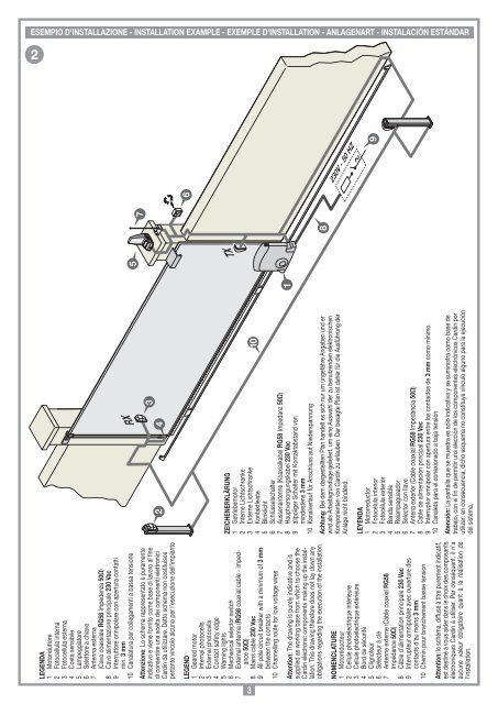
ESEMPIO D'INSTALLAZIONE - INSTALLATION EXAMPLE - EXEMPLE D'INSTALLATION - ANLAGENART - INSTALACIÓN ESTÁNDAR<br />
2<br />
230V - 50 HZ<br />
7<br />
TX<br />
1<br />
5<br />
6<br />
RX<br />
LEGENDA<br />
1 Motoriduttore<br />
2 Fotocellula interna<br />
3 Fotocellula esterna<br />
4 Costa sensibile<br />
5 Lampeggiatore<br />
6 Selettore a chiave<br />
7 Antenna esterna<br />
(Cavo coassiale RG58 Impedenza 50Ω)<br />
8 Cavo alimentazione principale 230 Vac<br />
9 Interruttore onnipolare con apertura contatti<br />
min. 3 mm<br />
10 Canalatura per collegamenti a bassa tensione<br />
Attenzione: Lo schema rappresentato è puramente<br />
indicativo e viene fornito come base di lavoro al fine<br />
di consentire una scelta dei componenti elettronici<br />
<strong>Cardin</strong> da utilizzare. Detto schema non costituisce<br />
pertanto vincolo alcuno per l'esecuzione dell'impianto<br />
LEGEND<br />
1 Geared motor<br />
2 Internal photocells<br />
3 External photocells<br />
4 Contact safety edge<br />
5 Warning lights<br />
6 Mechanical selector switch<br />
7 External antenna (RG58 coaxial cable - impedance<br />
50Ω)<br />
8 Mains cable 230 Vac<br />
9 All pole circuit breaker with a minimum of 3 mm<br />
between the contacts<br />
10 Channelling route for low voltage wires<br />
Attention: The drawing is purely indicative and is<br />
supplied as working base from which to choose the<br />
<strong>Cardin</strong> electronic components making up the installation.<br />
This drawing therefore does not lay down any<br />
obligations regarding the execution of the installation.<br />
NOMENCLATURE<br />
1 Motoréducteur<br />
2 Cellule photoélectrique intérieure<br />
3 Cellule photoélectrique extérieure<br />
4 Bord de sécurité<br />
5 Clignoteur<br />
6 Sélecteur à clé<br />
7 Antenne externe (Câble coaxial RG58<br />
Impédance 50Ω)<br />
8 Câble d’alimentation principale 230 Vac<br />
9 Interrupteur omnipolaire avec ouverture des<br />
contacts d'au moins 3 mm.<br />
10 Chemin pour branchement basse tension<br />
Attention: le schéma, diffusé à titre purement indicatif,<br />
est destiné à vous aider dans le choix des composants<br />
électroniques <strong>Cardin</strong> à utiliser. Par conséquent, il n'a<br />
aucune valeur obligatoire quant à la réalisation de<br />
l'installation.<br />
2<br />
4<br />
3<br />
ZEICHENERKLÄRUNG<br />
1 Getriebemotor<br />
2 Interne Lichtschranke<br />
3 Externe Lichtschranke<br />
4 Kontaktleiste<br />
5 Blinklicht<br />
6 Schlüsselschalter<br />
7 Aussenantenne (Koaxialkabel RG58 Impedanz 50Ω)<br />
8 Hauptversorgungskabel 230 Vac<br />
9 allpoliger Schalter mit Kontaktabstand von<br />
mindestens 3 mm<br />
10 Kanalverlauf für Anschluss auf Niederspannung<br />
Achtung: Bei dem dargestellten Plan handelt es sich nur um ungefähre Angaben und er<br />
wird als Arbeitsgrundlage geliefert, um eine Auswahl der zu benutzenden elektronischen<br />
Komponenten von <strong>Cardin</strong> zu erlauben. Der besagte Plan ist daher für die Ausführung der<br />
Anlage nicht bindend.<br />
10<br />
LEYENDA<br />
1 Motorreductor<br />
2 Fotocélula interior<br />
3 Fotocélula exterior<br />
4 Banda sensible<br />
5 Relampagueador<br />
6 Selector con llave<br />
7 Antena exterior (Cable coaxial RG58 Impedancia 50Ω)<br />
8 Cable de alimentación principal 230 Vac<br />
9 Interruptor omnipolar con apertura entre los contactos de 3 mm como mínimo.<br />
10 Canaleta para el conexionado a baja tensión<br />
Atención: La pantalla que se muestra es sólo indicativa y se suministra como base de<br />
trabajo, con el fin de permitir una elección de los componentes electrónicos <strong>Cardin</strong> por<br />
utilizar; en consecuencia, dicho esquema no constituye vínculo alguno para la ejecución<br />
del sistema.<br />
8<br />
9<br />
3