Elettropompa autoadescante a canale laterale ... - World of Heating
Elettropompa autoadescante a canale laterale ... - World of Heating
Elettropompa autoadescante a canale laterale ... - World of Heating

Create successful ePaper yourself
Turn your PDF publications into a flip-book with our unique Google optimized e-Paper software.
<strong>Elettropompa</strong> <strong>autoadescante</strong> a <strong>canale</strong> <strong>laterale</strong>Self-priming side channel electric pumpElectropompe autoamorçante à canal lateralSelbstansaugende Elektropumpe mit SeitenkanalTipi:Types:Types:Typen:EEM 20 ENM 20 ENT 20 ECC 12/20 ALM 20 ALT 20 AL 12/20EEM 25 ENM 25 ENT 25 ECC 24/20 ALM 20 L ALT 25 AL 24/20EEM 30 ENM 25S ENT 25S ECC 12/25 ALM 25 ALT 30 AL 12/25EEM 35 ENM 30 ENT 30 ECC 24/25 ALM 30 ALT 40 AL 24/25EEM 40 ENM 35 ENT 35 ECC 24/40 ALM 40 ALT 50 AL 24/40ENM 40 ENT 40 ALM 50ENM 50 ENT 50IGBFDMANUALE D’USO E MANUTENZIONEINSTRUCTIONS FOR USE AND MAINTENANCELIVRET D’EMPLOI ET D’ENTRETIENBEDIENUNGS- UNDINSTANDHALTUNGSANLEITUNGEd.: 01 Rev.: 5
Fig. 1Fig. 22
Fig. 3Fig. 4AFig. 4BFig. 5 Fig. 6Fig. 7 Fig. 83
Fig. 9Fig. 10 Fig. 11Fig. 12Fig. 13Fig. 14Fig. 15 Fig. 16 Fig. 17rif. 67Fig. 18Fig. 19 Fig. 20 Fig. 21Fig. 22Fig. 23 Fig. 24 Fig. 254
AVVERTENZALeggere attentamente tutte le istruzioni prima di utilizzare il prodotto. Persone non a conoscenza delle istruzioni per l’usonon devono utilizzare il prodotto. L’utilizzo della pompa non è permesso a persone di età inferiore a 16 anni.Il presente manuale descrive l’utilizzo della macchina previsto dalle ipotesi di progetto, le caratteristiche tecniche, le modalità diinstallazione, uso e manutenzione e le informazioni riguardanti i rischi connessi.Il manuale di istruzioni è da considerarsi parte dell’apparecchio e deve essere conservato per futuri riferimenti per tutta la vita dellamacchina. Se ne raccomanda la conservazione in luogo asciutto e protetto.Il manuale rispecchia lo stato della tecnica al momento della commercializzazione della macchina e non può essere consideratoi n adeguato solo perchè successivamente aggiornato in base a nuove esperienze. Il fabbricante si riserva il diritto di aggiornare laproduzione e i manuali senza l’obbligo di aggiornare produzione e manuali precedenti.Il fabbricante si ritiene sollevato da ogni responsabilità nei casi di:uso improprio della macchinauso contrario alla normativa nazionale specificainstallazione non correttadifetti di alimentazionemodifiche e interventi non autorizzatiutilizzo di ricambi non originali o non relativi al modello specificoinosservanza totale o parziale delle istruzioni1 - IMPIEGO DELLA MACCHINALa macchina è un’elettropompa <strong>autoadescante</strong> del tipo “a <strong>canale</strong> <strong>laterale</strong>”; risulta ideale nelle operazioni di travaso e movimentazionedi molti liquidi grazie ad alcune importanti caratteristiche:facilità di installazione, uso e manutenzione;capacità di auto-adescamento, cioè di aspirare l’aria contenuta nel tubo di aspirazione per iniziare il pompaggio;l’esaurimento del liquido nel serbatoio da cui si aspira non danneggia la pompa;possibilità di invertire il flusso di liquido (solo per i modelli con alimentazione in corrente alternata);funzionamento dolce (la velocità periferica della girante è contenuta).E’ concepita per uso pr<strong>of</strong>essionale.I nuovi modelli di pompe ed elettropompe in bronzo, nati da 30 anni di esperienza nella costruzione di pompe, hanno accentuato lecaratteristiche di versatilità; questi i nuovi aspetti:assenza assoluta di perdite di liquido;non c’è contatto fra il liquido e la flangia del motore in alluminio (assai corrodibile);filettatura delle bocche unificata (GAS).1.1 - SPECIFICHE SUL LIQUIDO POMPATO- Privo di particelle dure in sospensione (sabbia, ghiaia, etc.) che provocano una rapida usura delle parti interne; se queste sonopresenti installare nel tubo di aspirazione un adatto filtro.- Non aggressivo nei confronti dei materiali con cui entra in contatto, cioè:1) il materiale che costituisce il corpo della pompa e la girante (bronzo per serie EEM, ENM, ENT, ECC e acciaio inox AISI 316 perle serie AL);2) il materiale da cui è costituito l’albero (acciaio inox AISI 316);3) i materiali che costituiscono il dispositivo di tenuta (vedi capitolo 2.5).- Viscosità: sono da escludere liquidi troppo viscosi (paste, miele,...); indicativamente considerare come limite massimo la viscositàdi un olio minerale tipo SAE 30 alla temperatura di 30 ° C.- Densità: max 1.1 g/cm3- Temperatura minima: -15° C (o comunque superiore alla temperatura di congelamento del liquido da pompare).- Temperatura massima: 90° C (guarnizioni in NBR) o 130° C (guarnizioni in Viton); tali massimi sono condizionati dalla temperaturaambiente e dal luogo di installazione, che deve essere aperto e ventilato.VERSIONI CON CORPO POMPA IN BRONZO (serie EEM, ENM, ENT, ECC)Esempi di impiego: acqua, acqua di mare, olio minerale, gasolio, saponi; proprio perchè in bronzo, nei paesi dell’UnioneEuropea non sono idonee all’uso con prodotti alimentari.VERSIONI CON CORPO POMPA IN ACCIAIO INOX AISI 316 (serie AL)Offrono eccellente resistenza alla corrosione e all’abrasione.5I
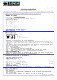
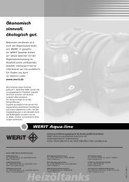
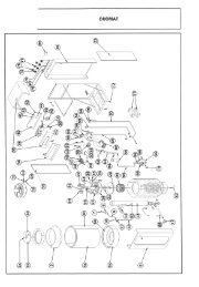
Esempi di impiego:- gli stessi liquidi consentiti per le pompe in bronzo, garantendo in questo caso una durata della macchina assai superiore;- liquidi corrosivi compatibili;- liquidi alimentari, ad esempio: vino, aceto, olio di oliva, latte (solo con le guarnizioni in NBR fornite di serie oppure in teflon); pertali impieghi è necessario adottare opportuni metodi per il lavaggio e la disinfezione della pompa, a seconda del tipo di liquido(vedere capitolo 5.1).I M P O R TA N T EE ’ vietato l’uso dell’elettropompa in ambienti che presentano rischio di esplosione e incendio (definiti dallenorme di legge); in particolare non deve essere utilizzata per pompare liquidi per i quali le norme stesseprescrivono l’uso di motore antideflagrante; esempi di impieghi assolutamente vietati sono: benzina,a c etone, solventi, etc.(Riferimenti normativi: norme internazionali IEC 79-10, norme italiane CEI 64-2)1.2 - AMBIENTE DI UTILIZZO- Luogo chiuso, pulito e asciutto (la pompa non è sommergibile).- Atmosfera normale o marina.- Temperatura ambiente compresa fra -15° C e 40° C.- Umidità relativa massima 80%.- Altitudine massima 1000 metri.2 - DESCRIZIONE TECNICA2.1 - CARATTERISTICHELa pompa è in grado di aspirare liquido da una bocca (bocca di aspirazione) e inviarlo dall’altra bocca (bocca di mandata); grandezzafondamentale che caratterizza una pompa è la portata Q (quantità di liquido spostata in un dato tempo); da questa dipendela velocità dell’operazione di pompaggio.La portata di una pompa non è fissa, dipende dalla prevalenza manometrica totale H richiesta dall’installazione, che è la sommadi due contributi:1) differenza di altezza (misurata in verticale) fra il livello del liquido nel serbatoio di mandata e quello del serbatoio di aspirazione;2) le perdite di energia causate dallo scorrimento del liquido nei condotti, valvole, raccordi, e altri elementi inseriti nel suo percorso.La seguente tabella (Tab. A) indica la portata (in litri/minuto) in funzione della prevalenza manometrica totale (in metri) per i vari tipidi elettropompa; i dati sono riferiti al funzionamento con acqua pulita a 20° C; le tolleranze sono quelle previste dalle norme ISO2548 per pompe prodotte in serie della categoria C.Viene anche indicato il valore della prevalenza massima sviluppata dalla pompa, che si raggiunge quando la bocca di mandata èchiusa. Tale valore è espresso in metri; può essere anche espresso come pressione (quindi in bar); approssimativamente 10 matricorrispondono a 1 bar di pressione. Tale dato è importante in quanto il tubo di mandata deve essere scelto tale da resistere a questapressione massima.La tabella Tab. A indica anche per ogni modello il livello di pressione acustica equivalente ponderato A (LeqA) nelle seguenticondizioni:- Ambiente operativo, pompa posizionata a 0.8 metri di altezza dal suolo- Rilevazione a 1 metro dalla superficie della macchina e a 1.60 metri dal suolo- Funzionamento con acqua a 20° C alla prevalenza in corrispondenza della quale la rumorosità risulta massima.2.2 - DISTINTA DEI COMPONENTILa tabella Tab. B contiene la distinta globale dei componenti, che si riferisce alle fig. 1, 2, 3, 4A, 4B.- fig. 1 rappresenta il disegno esploso dell’elettropompa con motore mon<strong>of</strong>ase tipo ENM 20, ALM 20 e ALM 20 L; il modello EEM20 si differenzia perchè al posto dell’interruttore rotativo è presente un interruttore basculante; i modelli con motore trifase tipo ENT20 e ALT 20 si differenziano per la mancanza del condensatore;- fig. 2 rappresenta il disegno esploso dell’elettropompa con motore mon<strong>of</strong>ase tipo ENM 25, ENM 25S, ENM 30, ENM 35, ENM 40,ENM 50, ALM 25, ALM 30, ALM 40, ALM 50; i tipi EEM 25, EEM 30, EEM 35, EEM 40 si differenziano da questi perchè al postodell’interruttore rotativo è presente un interruttore basculante; i modelli con motore trifase tipo ENT 25, ENT 25S, ENT 30, ENT 35,ENT 40, ENT 50, ALT 25, ALT 30, ALT 40, ALT 50 si differenziano per la mancanza del condensatore;- fig. 3 rappresenta i componenti della parte motore delle elettropompe con motore a corrente continua; le pompe ECC 12/20, ECC24/20, AL 12/20, AL 24/20 hanno la parte motore come in fig. 3 e la parte pompa come in fig. 1; ECC 12/25, ECC 24/25, ECC 24/40,AL 12/25, AL 24/25, AL 24/40 hanno la parte motore come in fig. 3 e la parte pompa come in fig. 2.- fig. 4B rappresenta la tenuta meccanica con la sua componentistica nei modelli con corpo pompa in acciaio inox e in bronzo tipo20; fig. 4A rappresenta la tenuta meccanica con la sua componentistica negli altri modelli; nei modelli in cui è presente sostituisceil n° 67 (fig. 1 e 2); la rondella tenuta (rif. 14) non è presente in tutti i modelli.6
TIPO 1 m 5 m 10 m H max LeqA TIPO 1 m 5 m 10 m H max LeqA(m) (dB) (m) (dB)EEM 20, ENM 20, ENT 20 32 27 21 27 77 ECC 24/25 67 50 26 19 75EEM 25, ENM 25, ENT 25 53 38 16 13 71 ECC 24/40 166 125 70 20 80ENM 25S, ENT 25S 97 92 85 48 83 ALM 20 L 11 2 6
Il verso tipico di pompaggio corrispondente alle posizioni 1 e 2 per pompe con motori mon<strong>of</strong>ase è illustrato in fig. 8 (seconda eterza riga); esso non è impegnativo, in alcuni esemplari potrebbe essere invertito.Nelle pompe con motore trifase il verso dipende anche dal collegamento alla rete.Nelle elettropompe con motore in corrente continua il verso di pompaggio è fisso e indipendente dal collegamento dei cavi dia l imentazione alla morsettiera; tale verso (tipico, ma va verificato all’atto dell’installazione) è illustrato in fig.8 (prima riga).2.5 - DISPOSITIVI DI TENUTALa girante, cioè l’organo meccanico rotante che permette il funzionamento della pompa viene azionata tramite un albero dal motoreesterno; nel corpo pompa esiste un’apertura per il passaggio dell’albero. La “tenuta” è quel dispositivo che impedisce la fuga delliquido attraverso lo spazio che necessariamente esiste fra l’albero rotante e l’apertura nel corpo pompa. Le pompe “TELLARINI”adottano due tipi di tenuta:- tenuta ad anello (paraolio) con molla inox; pregi: basso costo e maggiore attitudine al funzionamento sporadico; difetto:usura che nel tempo si produce sull’albero in corrispondenza del labbro del paraolio;- tenuta meccanica ceramica/grafite (vedi fig. 4); pregi: grande numero di ore di lavoro prima di interventi di riparazione eassenza di usura dell’albero; difetto: costo più elevato.Entrambe queste tenute possono essere fornite con parti in gomma realizzate in NBR o in VITON; la scelta dipende dal tipo dil i q u ido e dalla sua temperatura.- NBR è adatto per uso generale e per temperature non troppo elevate (max 90° C).- VITON : per temperature più elevate (fino a 130 °C) o per liquidi aggressivi.Queste sono indicazioni generali; per una scelta sicura è opportuno riferirsi ad affidabili tabelle di compatibilità chimica o consultareil nostro ufficio tecnico.La tabella Tab. C riporta i tipi di tenuta forniti di serie o su richiesta per ogni modello.2.6 - ACCESSORI DISPONIBILI- Manico (per tutti i modelli tipo 20 e 25, per EEM 30 e EEM 40) o c a r r e l l o (per tutti i tipi): tali accessori hanno lo scopo dif a c i l i t are il trasporto;- by-pass manuale integrato nella pompa per la regolazione della portata e della prevalenza; le relative istruzioni per l’uso sonoincluse in questo manuale.- tappo di scarico, per svuotare il corpo pompa senza rimuovere i tubi.3 - NORME PER L’INSTALLAZIONE E L’USO3.1 - MOVIMENTAZIONENon è previsto l’uso di mezzi di sollevamento; in targa è riportato il peso dell’elettropompa; per i modelli di peso superiore a 20 kgsi consiglia che due persone effettuino la movimentazione; qualora lo spostamento debba avvenire di frequente sono disponibiliaccessori per facilitarlo: manico (per i modelli più leggeri) o carrello; non trasportare mai la pompa servendosi dei cavi di allacciamentoall’alimentazione.3.2 - INSTALLAZIONE E USO1) Dopo aver tolto la pompa dall’imballaggio, prima di procedere all’installazione verificare l’integrità di tutte le sue parti: eventualirotture verificatesi durante il trasporto possono generare pericoli di natura meccanica (per esempio se la calotta copriventola è rotta)o elettrica (se la scatola porta invertitore è rotta).2) Montare il manico o il carrello, se disponibili, come illustrato in fig. 5 (manico) e fig. 6 (carrello).3 ) Posizionare la pompa in un luogo asciutto su un piano orizzontale; se la caduta della pompa dal piano di appoggio rappresenta unpericolo (per esempio se essa è posizionata in alto) essa deve essere fissata tramite bulloni (vedere come esempio la modalità con cuila pompa viene fissata al carrello, fig. 6); si raccomanda di non trascurare questo aspetto; la caduta della pompa può essere dovuta a:vibrazioni durante il funzionamentoimpigliamento da parte di persone nei tubiimpigliamento da parte di persone nel cavo di alimentazione.Non appendere o fissare mai la pompa servendosi dei cavi di allacciamento all’alimentazione.4) Riempire il corpo pompa di liquido da pompare attraverso una delle bocche; poichè la pompa è auto-adescante, tale operazioneè necessaria solo per il primo adescamento oppure se la pompa è stata svuotata; infatti all’arresto della stessa, anche se le tubazionisi svuotano, rimane all’interno la quantità di liquido sufficiente all’adescamento. E’ possibile anche un altro tipo di posizionamento(es. su un piano verticale) ma in questa posizione la pompa non è più auto-adescante.N O TA : sulle pareti interne del corpo pompa possono essere presenti tracce di sostanze lubrificanti (fluidi da taglio, grassi).Nel caso che queste sostanze possano contaminare il liquido pompato (in particolare se si tratta di sostanze alimentari),seguire all’atto della prima installazione la seguente procedura:- riempire il corpo pompa di soluzione detergente (es. sapone liquido);- lasciare agire;- sciaquare l’interno del corpo pompa pompando acqua pulita (vedere il seguito delle istruzioni di installazione);5) Pompe in bronzoAvvitare alle bocche i raccordi portagomma come visibile in fig. 5 o fig. 6, dopo essersi accertati della presenza delle guarnizioninei raccordi stessi; la disposizione mostrata è solo indicativa, i due raccordi dritto e curvo possono essere scambiati; la coppia diraccordi fornita di serie consente di adattarsi alla maggior parte delle applicazioni.8
Pompe in acciaio inoxI raccordi in nylon forniti su richiesta sono realizzati in 3 pezzi; utilizzare nastro di PTFE per uso idraulico per assicurare la tenuta frala bocca della pompa e il nipple; la tenuta fra il nipple e il raccordo è realizzata tramite accoppiamento conico, senza guarnizioni.6) Inserire le estremità delle tubazioni nei raccordi portagomma; il diametro interno dei tubi deve essere uguale a quello esterno deiraccordi; assicurare il collegamento tramite fascette stringitubo; la tubazione di aspirazione deve essere antischiacciamento, latubazione di mandata deve potere resistere alla pressione massima generata dalla pompa (vedere Tab. A e capitolo 2.1); siccomela pompa è <strong>autoadescante</strong> non è necessario installare una valvola di ritegno; inserire l’estremità libera del tubo di aspirazione nellacisterna da cui si vuole prelevare il liquido, quella del tubo di mandata nella cisterna in cui si vuole inviare il liquido; i tubi non devonoesercitare pressione sulla pompa.ATTENZIONE: All’avviamento della pompa per effetto della pressione del liquido il tubo di mandata si può sfilare dallacisterna e spruzzare nell’ambiente circostante; è quindi opportuno che il tubo stesso, se non tenuto in mano, sia fissato(in particolare nel caso di liquidi dannosi o combustibili, come il gasolio)7) Collegamento elettricoATTENZIONEI collegamenti elettrici devono essere effettuati in accordo alle prescrizioni della norma EN 60204-1 - 2. Ed.- Cavi e prese di collegamento devono essere controllati contro eventuali danni prima del loro impiego.- Assicurarsi che i collegamenti elettrici siano collocati in una zona al sicuro dalle inondazioni e, comunque, protetta dall’umidità.Nella versione di serie il motore elettrico non è fornito di protezione dai sovraccarichi; la predisposizione di tale protezioneè a cura dell’utilizzatore.Modelli a corrente alternata mon<strong>of</strong>ase e trifase- Accertarsi che l’interruttore sia in posizione di arresto (0).- Collegare il cavo di alimentazione alla rete dopo essersi accertati che tensione e frequenza coincidano con quelle riportate nellatarga del motore (sulla tensione è ammessa una tolleranza del 10%, sulla frequenza del 2%);AT T E N Z I O N E- La pompa deve essere assolutamente collegata ad una presa collegata a terra e protetta da un interruttore differenzialeda 30 mA.- La sezione dell’eventuale cavo di prolunga va scelta in base alla corrente di targa del motore (fare riferimentoalle norme vigenti).- La scatola porta invertitore contiene parti elettriche; il suo smontaggio può essere eseguito esclusivamente dapersonale esperto e qualificato, nel rispetto delle norme di sicurezza.- Nel caso dei modelli forniti privi di spina l’allacciamento alla rete deve essere eseguito da personale esperto.- Nel caso dei modelli forniti su richiesta con morsettiera, l’allacciamento alla rete deve essere eseguito da personaleesperto seguendo le indicazioni riportate all’interno del coperchio coprimorsettiera.Modelli alimentati in corrente continuaATTENZIONE:nel collegamento dei modelli a corrente continua al generatore di tensione di alimentazione,è obbligatorio rispettare la polarità (+, -) indicata sulla morsettiera.- Svitare le viti del coperchio copribasetta scoprendo la morsettiera.- In base alla corrente assorbita (vedere targa della pompa) predisporre una coppia di cavi elettrici di sezione adeguata.- Introdurre i cavi attraverso il passacavo.- Effettuare il collegamento alla morsettiera.- Avvitare il coperchio copribasetta.- Inserire nel circuito un interruttore, se non presente nella sorgente di alimentazione per un agevole avvio e arresto della pompa;accertarsi che sia in posizione “spento”.- Collegare ad un generatore di tensione continua di valore pari a quello indicato in targa (tolleranza 10%).8) Avviare la pompa commutando l’interruttore su una posizione di marcia; dopo qualche secondo necessario per l’adescamento lapompa comincia a travasare il liquido;ATTENZIONE: Se le connessioni dei tubi non sono state fatte correttamente, si possono verificare perdite o getti di liquido.Controllare se il tubo di aspirazione gorgoglia aria nel liquido da aspirare; in tal caso la pompa sta pompando nella direzione opposta:commutare l’interruttore sull’altra posizione di marcia oppure (modelli a corrente continua) invertire il collegamento dei tubi allebocche della pompa.9) Arresto della pompa: portare l’interruttore in posizione di arresto (0) oppure sconnettere il cavo dall’alimentazione; per un successivoavviamento non è necessario riempire nuovamente il corpo pompa di liquido. La pompa anche dopo lo spegnimento restapiena di liquido, condizione che consente l’adescamento; se esiste la possibilità che la temperatura esterna si abbassi sotto il puntodi congelamento del liquido, svuotare la pompa dopo l’uso per evitare la rottura del corpo pompa.IMPORTANTEa) La pompa non deve essere avviata prima di avere completato l’installazione;b) E’ assolutamente vietato introdurre dita o altre parti del corpo attraverso le bocche: la pompacontiene parti in movimento9
3.3 - USO DEL BY-PASSIl by-pass è un dispositivo di regolazione della portata e prevalenza della pompa fornito su richiesta; si presenta come una manopolao una levetta a seconda dei modelli; agendo su tale dispositivo l’utente è in grado di ridurre la portata massima fino a circa metàe la prevalenza massima fino a circa 1/4. Durante la fase di adescamento è necessario che il by-pass sia chiuso (manopola o levettacompletamente ruotate in senso orario); l’apertura del by-pass riduce enormemente l’adescamento.4 - AVVERTENZE4.1 - TEMPERATURA DELLE SUPERFICI ACCESSIBILILa temperatura della superfici accessibili della macchina dipende dalle condizioni d’uso (prevalenza erogata, tipo di liquido),dalla temperatura ambiente, dalla temperatura del liquido. Le superfici esterne del motore elettrico, con la corretta tensionedi alimentazione, la pompa funzionante con acqua fredda pulita a metà della prevalenza massima generabile, installatain luogo aperto e ventilato, raggiungono una temperatura superiore di circa 30° C alla temperatura ambiente; quandola temperatura complessiva supera i 50° C si consiglia di adottare adatte misure individuali di protezione (guanti) per maneggiarle.La superficie esterna del corpo pompa raggiunge la temperatura del liquido pompato; è necessario quindi adottare guanti per maneggiaretali superfici quando si pompano liquidi molto caldi o molto freddi.4.2 - RISCHI DOVUTI A PROIEZIONE DI LIQUIDOSi possono avere getti indesiderati di liquido nei seguenti casi:- Avviamento della pompa piena di liquido senza il tubo di mandata.- Montaggio dei raccordi male eseguito o mancanza delle relative guarnizioni.- Tubo di mandata difettoso o non adatto.- Deterioramento del dispositivo di tenuta e proiezione di liquido dallo spazio fra la flangia e il corpo pompa.- In caso di smontaggio, errato rimontaggio della guarnizione O-ring fra corpo e coperchio oppure suo deterioramento.Questi eventi generano rischi per l’utilizzatore quando il liquido sia ad alta temperatura o quando il contatto del liquido con il corpoumano sia da evitare. In questi casi è obbligatoria da parte dell’utilizzatore la massima cautela, eventualmente predisponendo dispositividi protezione (schermi) in posizione opportuna.4.3 - RISCHI DI INONDAZIONIDanni causati da inondazioni dovute al mancato funzionamento della pompa devono essere evitati a cura dell’utilizzatore con adeguatemisure di prevenzione (es. installazione di allarmi, pompe di riserva, etc.).5 - MANUTENZIONE5.1 - LAVAGGIOIl lavaggio della pompa può essere effettuato molto facilmente pompando acqua pulita; quando la pompa venga usata per sostanze alimentaripoco deperibili (vino, aceto) si consiglia per il lavaggio di pompare una adatta soluzione disinfettante (per esempio a base diacido peracetico), poi sciaquare l’interno del corpo pompa pompando acqua pulita fino all’eliminazione del disinfettante. Tale procedurava eseguita prima e dopo l’uso. Quando la pompa venga usata per liquidi alimentari rapidamente deperibili (come il latte), il lavaggiova effettuato frequentemente smontando la pompa e pulendo accuratamente le sue parti con modalità dipendenti dal tipo di liquido.5.2 - DIFETTI DI FUNZIONAMENTO / RICERCA GUASTID i f e t t oIl motore non giraIl motore è alimentato ma non giraCausa possibileMancanza di correnteGirante bloccataRimedioVerificare l’alimentazione elettricaFermare immediatamente la pompa, smontarla(vedi capitoli successivi), eliminare eventuali corpi estranei,ripristinare il corretto posizionamento della girante e rimontare.Il motore a corrente continua hafunzionamento irregolare o nonf u n z i o n aLa pompa non aspiraLa pompa durante il pompaggioproduce rumorosità irregolare(come di un ciottolo che rotola)La pompa non aspira operde liquidoLa pompa gorgoglia aria nelserbatorio di aspirazioneNessuna o bassa portata di liquidoSpazzole usurateAltezza di aspirazione troppo elevataLa pompa non è piena di liquidoIl tubo di aspirazione non è immersoLa pompa non è posizionata correttamenteAspirazione di corpi solidi duriRottura di parti della giranteLe guarnizioni o la tenuta sonodeteriorateVerso di pompaggio sbagliatoPrevalenza richiesta troppo altaLa pompa è intasataSostituire le spazzole (vedi cap. 5.6)Controllare l’altezza di aspirazioneRiempire la pompa di liquidoImmergere il tubo di aspirazioneVedere modalità installazioneControllare che non ci siano infiltrazioni d’aria neltubo di aspirazione e nei raccordiFermare immediatamente il pompaggio, smontare e pulirela pompa (vedi capitoli successivi)Fermare immediatamente il pompaggio, smontare e pulirela pompa, sostituire la giranteSostituire le guarnizioni e la tenuta (vedi capitolisuccessivi)Invertire il verso di pompaggioControllare la prevalenza richiestaSmontare e pulire la pompa (vedi cap. successivi)10
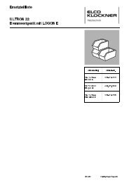
IMPORTANTE: La rumorosità che manifestano le pompe in bronzo tipi 20, 25, 30, 35 nel funzionamento a secco (che spariscedurante il pompaggio) non indica alcun guasto, deriva dal fatto che su questi modelli la girante è scorrevole sull’alberoper consentire una facile manutenzione.5.3 - SMONTAGGIO DELLA PARTE IDRAULICA DELLA POMPAIMPORTANTEPrima di procedere allo smontaggio e montaggio mettere s e m p r e l’interruttore in posizione “0” e scollegare l’apparecchiodalla rete di alimentazione per evitare accensioni accidentali con le parti in movimento non protette.Nelle parti interne ci possono essere spigoli taglienti; si consiglia quindi di maneggiare con cautela.Se non diversamente specificato, i riferimenti nel seguito vanno ricercati nelle fig. 1, 2, 3, 4A, 4B in base alle indicazioni nel paragrafo 2.2.- Svitare le viti (rif. 30 o rif. 31) del coperchio;- Rimuovere il coperchio (rif. 11)- Estrarre la girante (rif. 13) con le seguenti modalità.Modelli in bronzo tipo 20-25-30-35: la girante è scorrevole sull’albero (rif. 64), può essere estratta semplicemente con le dita.Modelli tipo 40-50 in bronzo e tutti i modelli inox: la girante è forzata sull’albero; per sfilarla utilizzare un estrattore con le griffeopportunamente sagomate (vedi fig. 7); nel mozzo della girante sono presenti due sporgenze a questo scopo (fig. 7); nel caso deimodelli inox tipo 20 utilizzare per l’estrazione le due sporgenze presenti lateralmente sul corpo pompa (rif. 10).- Rimuovere la linguetta (rif. 15) ;- Sfilare il corpo pompa (rif. 10) dall’albero;Modelli tipo 20 in bronzo- Sfilare la contr<strong>of</strong>langia (rif. 5) dal corpo pompa;- Togliere la guarnizione (rif. 8) dalla contr<strong>of</strong>langia.5.4 - MONTAGGIO DELLA PARTE IDRAULICA DELLA POMPA(per i modelli in bronzo tipo 20, prima inserire la contr<strong>of</strong>langia (rif. 5) e posizionare la guarnizione (rif. 8);- Inserire la linguetta (rif. 15) nella sua sede- Inserire il corpo pompa (rif. 10) lungo l’albero (rif. 64)- Posizionare la guarnizione O-Ring (rif. 12) nella sua sede sul corpo pompaModelli a girante scorrevole- Inserire la girante (rif. 13) nell’albero con le dita;- Posizionare il coperchio (rif. 11) e stringere le viti (rif. 30 o rif. 31) avvitando gradualmente e alternativamente coppie di viti opposteM o delli a girante forzataL’inserimento va effettuato tramite un tubo di diametro interno superiore a quello dell’albero.- Colpendo il tubo con il martello accostare la girante (rif. 13) alla superficie di rasamento, lasciando 0.1 mm di gioco- Montare il coperchio (rif. 11) e stringere le viti (rif. 31) avvitando gradualmente e alternativamente coppie di viti opposte- Colpire il retro dell’albero (l’estremità su cui è montata la ventola motore (rif. 1) con un punzone e il martello.- Accendere la pompa e verificare che la girante ruoti liberamente; se risulta bloccata aprire la pompa, correggere la posizione dellagirante e riprovare.5.5.1 - SOSTITUZIONE DEL PARAOLIO (MODELLO IN BRONZO TIPO 20)In questo modello il paraolio (rif. 67) è alloggiato nella contr<strong>of</strong>langia (rif. 5); per la sostituzione:- appoggiare su un piano la contr<strong>of</strong>langia con il bordo rivolto in basso (fig. 22);- colpire il paraolio tramite un tronchetto tondo di dimensioni opportune fino a sfilarlo;- appoggiare la contr<strong>of</strong>langia sull’altro lato;- prendere il paraolio nuovo e appoggiarlo all’ìmboccatura della sua sede con la giusta orientazione (la molla deve essere rivoltaverso l’interno della pompa) come visibile in fig. 23;- inserire il paraolio nella sua sede colpendolo tramite un tronchetto tondo di dimensioni opportune;5.5.2 - SOSTITUZIONE DEL PARAOLIO (MODELLI IN BRONZO TIPO 25-30-35-40)Il corpo della pompa è realizzato in due pezzi: Corpo pompa (rif. 10) e Parte interna posteriore (rif. 65), la quale viene inserita nelCorpo pompa (in fig. 2 sono visibili le due parti smontate, in fig. 9 dopo il montaggio). Per sostituire il paraolio (rif. 67) è necessarioestrarre la parte interna posteriore dal corpo pompa. Le illustrazioni cui si fa riferimento nel seguito rappresentano le parti in sezione.- Appoggiare il corpo pompa su due appoggi di materiale tenero (es. legno o alluminio) oppure di qualsiasi materiale purchè si interponganodue pezzetti di carta (fig. 10).- Prendere un tronchetto di tondo (in metallo, legno, materiale plastico) con le dimensioni indicate in fig. 10 e colpire il paraolio finoa sfilarlo dalla sua sede (fig. 11).- Appoggiare il paraolio al bordo della parte interna posteriore e colpire di nuovo con il martello (fig. 12); la parte interna verrà estrattaassieme al paraolio (fig. 13).- Appoggiare il corpo pompa su un piano (fig. 14); prendere il paraolio nuovo e appoggiarlo all’ìmboccatura della sua sede con lagiusta orientazione (la molla deve essere rivolta verso l’interno della pompa).- Tramite un tronchetto tondo di diametro di poco inferiore a quello esterno del paraolio e un martello inserire il paraolio nella suasede (fig. 15 e 16).- Appoggiare la parte interna posteriore sul corpo (fig. 17 e 19) con la giusta orientazione (fig. 18).- Inserire la parte interna nel corpo tramite un tronchetto tondo di dimensioni opportune (fig. 20 e 21).11
5.5.3 - SOSTITUZIONE DEL PARAOLIO (MODELLO IN BRONZO TIPO 50)Questo modello di pompa ha la stessa struttura dei modelli 25-30-35-40 ma per lo smontaggio e montaggio del paraolio non è necessariotogliere la parte interna posteriore;- appoggiare il corpo pompa (rif. 10) montato con la parte interna posteriore (rif. 65) su un piano (fig. 24);- colpire il paraolio (rif. 67) tramite un tronchetto tondo di dimensioni opportune fino a sfilarlo- rovesciare il corpo pompa (fig. 25);- prendere il paraolio nuovo e appoggiarlo all’ìmboccatura della sua sede con la giusta orientazione (la molla deve essere rivolta versol’interno della pompa);- inserire il paraolio nella sua sede colpendolo tramite un tronchetto tondo di diametro di poco inferiore a quello del paraolio e il martello.5.5.4 - SOSTITUZIONE TENUTA MECCANICA- Eseguire la procedura di smontaggio senza sfilare il corpo pompa; per i modelli tipo 20 togliere anche il corpo (rif. 10), sfilandolodalla contr<strong>of</strong>langia (rif. 5);- (modelli con la componentistica di fig. 4A) tramite le apposite pinze togliere il seeger tenuta (rif. 9A);- (modelli con la componentistica di fig. 4B) tramite una adatta chiave, svitare le tre viti dell’anello d’arresto tenuta (rif. 9B) e sfilarlodall’albero (per i modelli diversi dal tipo 20 occorre inserire la chiave attraverso la bocca del corpo pompa);- sfilare in successione la rondella tenuta (rif. 14) quando presente, la parte rotante tenuta (rif. 67A) , la contr<strong>of</strong>accia (rif. 67B) e lacuffia (rif. 67C);- prendere una tenuta identica, separare cuffia e contr<strong>of</strong>accia, pulire con un panno morbido le piste lappate della parte rotante e dellacontr<strong>of</strong>accia, sgrassare l’alloggiamento nel corpo pompa e nell’albero, lubrificare le parti in gomma con acqua e sapone;- inserire la cuffia nella sede nel corpo pompa, poi la contr<strong>of</strong>accia;. inserire la parte rotante della tenuta facendo molta attenzione che le sue parti in gomma non si danneggino quando transitano suparti taglienti;- (Modelli con la componentistica di fig. 4A) inserire la rondella e, tenendo premuta la molla della parte rotante, inserire il seeger nellasua sede.- (Modelli con la componentistica di fig. 4B) inserire la rondella (quando presente) e l’anello d’arresto; tenendo premuto l’anello d’arrestocontro le altre parti della tenuta meccanica (per es. tramite un tubo) serrarne le viti tenendo presente che la lunghezza assialedella parte rotante a montaggio ultimato deve essere fra 13 e 14 mm.5.6 - SOSTITUZIONE DELLE SPAZZOLENei modelli con motore in corrente continua le spazzole (rif. 7) sono contatti striscianti soggetti ad usura continua durante il funzionamento;l’usura è fortemente dipendente dal valore effettivo della tensione di alimentazione; la spazzola è completamente usurataquando la molla che la spinge contro il collettore è a fine corsa; quando le spazzole si stanno usurando completamente si nota uncomportamento irregolare del motore; per la sostituzione:- togliere la calotta copriventola (rif. 2)- svitare le 2 viti sul portaspazzole (rif. 6) che collegano i cavi delle spazzole all’avvolgimento del motore;- sfilare le spazzole alzando le molle che le tengono premute, sostituirle, avvitare le 2 viti;- rimontare la calotta copriventola;DICHIARAZIONE DI CONFORMITA’La Ditta TELLARINI POMPE s.n.c di G. Tellarini & C. con sede in via Majorana, 4 - Lugo (RA) - Italia dichiara sotto la propria esclusivaresponsabilità che le elettropompe autoadescanti a <strong>canale</strong> <strong>laterale</strong> tipi:EEM 20 ENM 20 ENT 20 ECC 12/20 ALM 20 ALT 20 AL 12/20EEM 25 ENM 25 ENT 25 ECC 24/20 ALM 20 L ALT 25 AL 24/20EEM 30 ENM 25S ENT 25S ECC 12/25 ALM 25 ALT 30 AL 12/25EEM 35 ENM 30 ENT 30 ECC 24/25 ALM 30 ALT 40 AL 24/25EEM 40 ENM 35 ENT 35 ECC 24/40 ALM 40 ALT 50 AL 24/40ENM 40 ENT 40 ALM 50ENM 50 ENT 50alle quali questa dichiarazione si riferisce sono conformi:- ai requisiti essenziali di sicurezza previsti dalle direttive 89/392/CEE, 91/368/CEE, 93/44/CEE, 93/68/CEE, quando utilizzate inosservanza alle prescrizioni contenute nel manuale d’uso e manutenzione;- alle prescrizioni della direttiva 89/336/CEE;- alle prescrizioni della direttiva 73/23/CEE, modificata dalla 93/68/CEE (con riferimento ai prodotti a cui tale direttiva si applica);Il rappresentante legale12
GBCAUTIONRead all instructions carefully before operating the appliance; people who do not know the instructions for use must notuse the appliance; people under 16 years are not allowed to use the pump.This handbook describes the use <strong>of</strong> the machine following the plan hypotheses, the specifications, the instructions for installation,use and maintenance and all information concerning the connected risks.The handbook is to be considered as part <strong>of</strong> the appliance and must be kept for future references for the whole life <strong>of</strong> the machine.We recommend to keep it in a dry and protected place.The handbook mirrors the state <strong>of</strong> technology at the moment <strong>of</strong> the marketing <strong>of</strong> the machine and cannot be considered as inadequateonly because <strong>of</strong> further revision on the basis <strong>of</strong> new experiences. The manufacturer reserves the right to modify the productionand the handbooks without any obligation to update the previous production and handbooks. The manufacturer is not responsiblein the cases <strong>of</strong>:- improper use <strong>of</strong> the machine- use contrary to the specific national law- incorrect installation- operation with incorrect voltage- unauthorized changes and interventions- use <strong>of</strong> not original spare parts or not belonging to the specific model- complete or partial non-compliance with the instructions1 - USE OF THE MACHINEThe machine is a side channel self-primimg electric pump, it is ideal for the transfer and handling <strong>of</strong> a lot <strong>of</strong> liquids thanks to someimportant characteristics:- easiness <strong>of</strong> installation, use and maintenance- self-priming capability, i.e. <strong>of</strong> draining away the air contained in the suction pipe to begin the pumping <strong>of</strong> liquid;- the exhaustion <strong>of</strong> the liquid in the tank from which it is being pumped out does not damage the pump;- possibility to reverse the liquid flow (only for the models with alternating current motor)- s<strong>of</strong>t operation ( the peripheral speed <strong>of</strong> the pump impeller is limited);It is conceived for pr<strong>of</strong>essional use.The new models <strong>of</strong> pumps and electric pumps <strong>of</strong> bronze, the fruit <strong>of</strong> 30 years <strong>of</strong> experience in pump manufacturing, have increasedtheir versatility characteristics.- absolute absence <strong>of</strong> liquid leaks;- no contact <strong>of</strong> the liquid with the aluminium flange, highly subject to corrosion;- standard hose thread (GAS).1.1 - CHARACTERISTICS OF THE PUMPED LIQUID- Without suspended hard particles (sand, gravel, etc.) that provoke a rapid wear <strong>of</strong> the inside parts; if these are present, installa suitable filter in the suction pipe.- Non-corrosive towards the materials it comes into contact with, , i.e. <strong>of</strong>:1) the material <strong>of</strong> the pump body and impeller (bronze in series EEM, ENM, ENT, ECC and stainless steel AISI 316 in seriesA L );2) the material <strong>of</strong> the shaft (stainless steel AISI 316)3) the materials <strong>of</strong> the seal (see chapter 2.5).- Viscosity: too viscous liquids (dough, honey) must be excluded; indicatively the viscosity <strong>of</strong> a mineral oil type SAE 30 at the temperature<strong>of</strong> 30° C can be considered as maximum limit.- Density: max 1.1 g/cm3- Minimum temperature: - 15° C (or in any case above freezing-point <strong>of</strong> the liquid to be pumped).- Maximum temperature: 90° C (seals in NBR) or 130° C (seals in Viton); these maximum temperatures are subject to the ambienttemperature and to the place <strong>of</strong> installation, that must be open and well-ventilated.MODELS WITH PUMP BODY OF BRONZE (SERIES EEM, ENM, ENT, ECC)Examples <strong>of</strong> use: water, sea water, mineral oil, gas oil, liquid soaps; as they are <strong>of</strong> bronze, in the countries <strong>of</strong> the European Unionthey are not suitable for food fluids.MODELS WITH PUMP BODY OF STAINLESS STEEL AISI 316 (SERIES AL)They <strong>of</strong>fer excellent resistance <strong>of</strong> the inside parts to corrosion and abrasion.13
Examples <strong>of</strong> use:- the same liquids suitable for bronze pumps, allowing in this case a much longer life <strong>of</strong> the machine;- compatible corrosive liquids;- ood liquids, e.g. wine, vinegar, olive oil, milk (only with the standard gaskets in NBR or with gaskets in TEFLON); for these usesit is necessary to adopt suitable methods to wash and disinfect the pump, according to the type <strong>of</strong> liquid (see chapter 5.1).I M P O R TA N TThe use <strong>of</strong> the electric pump in places presenting the risk <strong>of</strong> explosion and fire (defined according the lawstandards) is strictly forbidden; in particular it must not be used to pump the liquids for which the standardsprescribe the use <strong>of</strong> an explosion-pro<strong>of</strong> motor; absolutely forbidden uses are, for example, petrol,acetone, solvents, etc.(Standard references: international standards IEC 79-10, Italian standards CEI 64-2)1.2 - PLACE OF USE- Closed, dry and clean place (the pump is not submergible).- Normal or sea atmosphere- Ambient temperature between -15° C and 40° C- Maximum relative humidity 80%- Maximum altitude 1000 meters2 - TECHNICAL DESCRIPTION2.1 - SPECIFICATIONSThe pump sucks in the liquid from one hose (suction hose) and sends it to the other hose (delivery); a fundamental quantity thatcharacterizes the pump is the capacity Q (quantity <strong>of</strong> liquid transferred in a given time); the pumping operation speed dependson it.The capacity <strong>of</strong> a pump is not fixed, it depends on the total manometric head H required by the installation, which is the sum <strong>of</strong>two elements:1) the difference in height (vertically measured) between the level <strong>of</strong> the liquid in the delivery tank and that <strong>of</strong> the suction tank;2) energy losses provoked by pipes, valves, fittings and other elements inserted in the path <strong>of</strong> the liquid.The following table (Tab. A) indicates the capacity in liters/minute depending on the total manometric head (in meters) for the varioustypes <strong>of</strong> pumps; the table refers to the operation with clean water at 20° C. The tolerances are those admitted by the standard ISO2548 for mass-produced pumps <strong>of</strong> cathegory C.The table also indicates the value <strong>of</strong> the maximum head reached when delivery is closed. This value is expressed in meters; it canalso be expressed as pressure (therefore in bars); approximately 10 meters correspond to one bar. This value is important as thedelivery pipe must resist this maximum pressure.Tab. A also indicates the sound pressure equivalent level weighed A (LeqA) for each model in the following conditions:- operating ambient, pump placed at 0.8 meters height- measurement at one meter distance from the machine surface and at 1.60 meters from the ground- operation with clean water at 20° C at the head for which noise is highest.2.2 - COMPONENT LISTTable B contains the global components list, which refers to ill. 1,2,3,4.- ill. 1 shows the exploded drawing <strong>of</strong> the pump with single-phase motor type ENM 20, ALM 20, ALM 20 L; the model EEM 20 differsbecause there is a different switchreverser; the models ENT 20 and ALT 20, with three-phase motor, differ for the absence <strong>of</strong>the capacitor;- ill. 2 shows the exploded drawing <strong>of</strong> the pump with single-phase motor type ENM 25, ENM 25S, ENM 30, ENM 35, ENM 40, ENM50, ALM 25, ALM 30, ALM 40, ALM 50; the models EEM 25, EEM 30, EEM 35, EEM 40 differ because there is a different switchreverser;the models ENT 25, ENT 25S, ENT 30, ENT 35, ENT 40, ENT 50, ALT 25, ALT 30, ALT 40, ALT 50 with three-phase motordiffer for the absence <strong>of</strong> the capacitor;- ill. 3 shows the motor part components <strong>of</strong> direct current pumps; ECC 12/20, ECC 24/20, AL 12/20, AL 24/20 have motor part asshown in ill. 3 and pump part as shown in ill.1; pumps ECC 12/25, ECC 24/25, ECC 24/40, AL 12/25, AL 24/25, AL 24/40 have motorpart as shown in ill. 3 and pump part as shown in ill. 2;- ill. 4B shows the mechanical seal with its component parts in the models with pump body <strong>of</strong> stainless steel and in the models <strong>of</strong>bronze type 20; ill. 4A shows the mechanical seal with its component parts in the other models; when present it substitutes no. 67(ill. 1 and 2); the seal washer (ref. 14) is not present in all the models.14
T Y P E 1 m 5 m 10 m H max L e q A T Y P E 1 m 5 m 10 m H max L e q A( m ) ( d B ) ( m ) ( d B )EEM 20, ENM 20, ENT 20 32 27 21 27 77 ECC 24/25 67 50 26 19 75EEM 25, ENM 25, ENT 25 53 38 16 13 71 ECC 24/40 166 125 70 20 80ENM 25S, ENT 25 S 97 92 85 48 83 ALM 20 L 11 2 6 < 70EEM 30, EEM 35 89 68 38 15 74 ALM 20, A LT 20 32 27 21 27 77ENM 30, ENT 30 89 71 43 16 74 ALM 25, A LT 25 43 28 8 12 71ENM 35, ENT 35 89 71 43 16 74 ALM 30, A LT 30 89 80 70 42 83EEM 40 149 11 5 66 16 77 ALM 40, A LT 40 137 11 2 76 16 77ENM 40, ENT 40 149 11 9 78 17 77 ALM 50, A LT 50 205 176 140 29 82ENM 50 250 215 167 26 84 . 7 A L 12 / 20 23 16 5 14 75E N T 50 262 227 180 27 84 . 7 A L 24 / 20 26 20 9 16 76ECC 12/20 23 16 5 14 75 A L 12 / 25 49 36 17 13 74ECC 24/20 26 20 9 16 76 A L 24 / 25 54 42 23 15 75ECC 12/25 62 44 14 14 74 A L 24 / 40 146 11 2 65 15 80Tab. A1 Motor fan 12 O-Ring 31 Socket screw2 Fan cover 13 Impeller 61 Back motor cover3 Front bearing 14 Seal washer 62 Back bearing4 Pump flange 15 Impeller feather 63 Motor frame with stator5 Counter-flange 18 Capacitor (only single-phase) 64 Motor shaft with rotor6 Brush bearing 19 Switch reverser 65 Internal back part7 Brush 20 Switch reverser box 66 Internal front part8 Gasket 21 Terminal board cover 67 Seal9A Seal snap ring 22 Terminal board 67A Mechanical seal - rotating part9B Seal shaft collar 25 Straight fitting 67B Mechanical seal - fixed part10 Pump body 26 Curved fitting 67C Mechanical seal - rubber housing11 Pump cover 30 Hexagonal-headed screw 68 Lip sealTab. B2.3 - MAXIMUM PRIMING HEIGHTPriming is the maximum difference in height between the pump and the level <strong>of</strong> the liquid to be pumped with which the pump is ableto suck in the air from the suction pipe and start pumping; a typical value <strong>of</strong> priming is six meters; yet the real value greatly dependson the quantity <strong>of</strong> liquid within the pump during the priming phase; it depends on the way <strong>of</strong> installation and on the pattern <strong>of</strong> thepipes; to obtain the highest priming performance the two following aspects must be considered:1) during priming the rotation <strong>of</strong> the impeller tends to discharge the liquid contained in the pump body through the delivery; this causesa reduction <strong>of</strong> the quantity <strong>of</strong> liquid and consequently <strong>of</strong> priming; this can be avoided adopting a pattern <strong>of</strong> the delivery pipe whichcompels the water discharged to come back;example: a piece <strong>of</strong> pipe, more than one meter long, inclined upwards with a difference in level <strong>of</strong> 20-40 cm.2) As to the suction hose, a piece <strong>of</strong> pipe inclined upwards (difference in level=20 cm) or vertical, increases remarkably the amount<strong>of</strong> liquid remaining within the pump after its stop.2.4 - SWITCHThe single-phase and three-phase electric pumps are reversible, that is it is possible to reverse the flow direction. In this way, thesuction hose becomes the delivery and vice versa. The reversal is obtained through a 3-position switch-reverser:0 = OFF1 = ON2 = ON (liquid flowing in the opposite direction with respect to position 1)TYPE OF SEAL STANDARD ON REQUESTLip seal in NBREEM, ENM, ENT, ECCLip seal in VITONENM, ENT, ECCMechanical seal ceramic/graphite/NBR AL ENM, ENT, ECCMechanical seal ceramic/graphite/VITONENM, ENT, ECC, ALTab. C15
The typical direction corresponding to positions 1 and 2 for pumps with single-phase motor is shown in ill. 8 (second and third line);it is not binding, in some models it could be inverted.In the pumps with three-phase motor the direction also depends on the connection to the power supply.The electric pumps with direct current motor are supplied without switch reverser and cable but with a terminal board for the connectionto the power supply; the flow direction is fixed, the way <strong>of</strong> connection to the power supply uninfluential. The typical direction(but it should be verified when installing the pump) is shown in the ill. 8 (first line).2.5 - SEALSThe impeller, that is the rotating mechanical unit allowing the pump operation, is driven through a shaft by the motor; an openingin the pump body allows the passage <strong>of</strong> the shaft. The “seal” is a device that prevents the liquid from leaking through the spacenecessarily existing between the rotating shaft and the opening in the pump body. “TELLARINI” pumps adopt two kinds <strong>of</strong> seal:- lip seal with stainless steel spring; good points: low cost, aptitude to be used occasionally; defect: the wear that, with thepassing <strong>of</strong> time, is produced on the shaft in correspondence with the seal lip;- mechanical seal ceramic/graphite; good points: a great number <strong>of</strong> hours <strong>of</strong> operation before repairs, absence <strong>of</strong> wear onthe shaft; defect: a higher cost.Both seals can be supplied with rubber parts made <strong>of</strong> NBR or VITON; the choice depends on the type <strong>of</strong> liquid and on its tempe r a t u r e .- NBR is suitable for general use and for not too high temperatures (max 90° C)- VITON is recommended for higher temperatures (up to 130° C) or for corrosive liquids.These are general instructions; for the right choice you should refer to reliable tables <strong>of</strong> chemical compatibility or consult our technicaldepartment. Tab. C presents the seal types supplied standard or on request for each model.2.6 - ACCESSORIES AT DISPOSAL- Handle (for all the models type 20 and 25, for EEM 30 and EEM 40) or truck (for all types) to make transport easy;- manual by-pass fitted in the pump to regulate its capacity and head; the instructions are included in this handbook;- drain plug , to empty the pump body without removing the pipes.3 - INSTALLING AND OPERATING INSTRUCTIONS3.1 - TRANSPORTThe use <strong>of</strong> handling equipments is not required; the weight <strong>of</strong> the pump is written on the plate; for models weighing over 20 kg thepump should be carried by two people; should the pump be frequently moved, some accessories are available to make the transporteasier: handle (for lighter models) or truck; never carry the pump using the electric cable.3.2 - INSTALLATION AND USE1) After unpacking the pump, before installing it check that all parts are intact: any break happened during transport may causemechanical hazard (e.g. if the fan cover is broken) or electrical hazard (e.g. if the switch reverser box is broken).2) Assemble the handle or truck, if present; see ill. 5 (handle) or 6 (truck).3 ) Place the pump in a dry place on a horizontal surface; if the downfall <strong>of</strong> the pump may cause hazards (for example if it is placed in ahigh position) it must be fixed with screws (see in the illustration 6 how the pump is fixed to the truck); the downfall may be caused by:- vibrations during operation- entanglement <strong>of</strong> a person in the pipes- entanglement <strong>of</strong> a person in the electric cable.Never hang or fix the pump using the electric cable.4) Fill the pump body with liquid through one <strong>of</strong> the hoses; as the pump is self-priming, this operation is necessary only for thefirst priming or when the pump has been emptied; when stopped, even if the pipes are emptied, a quantity <strong>of</strong> liquid sufficient forpriming remains within it. Also a different positioning is possible (e.g. on a vertical surface) but the pump loses its self-primingc a p a b i l i t y.WARNING: the inner walls <strong>of</strong> the pump may be dirty with traces <strong>of</strong> lubricants (grease, cutting fluid); if these substances cancontaminate the pumped liquid (for example if it is a food fluid), follow this procedure when you install the pump for the firstt i m e :- fill the pump with a detergent solution (e.g. liquid soap);- leave it operate;- rinse the pump body by pumping clean water (see the following installation instructions).5) Pumps <strong>of</strong> bronzeScrew the fittings down the pump hoses, as it is shown in the illustrations 5 and 6 after checking that the fittings are equippedwith gaskets; the position shown in the illustration is one <strong>of</strong> the two possible; the position <strong>of</strong> the straight and curved fittings can beinverted; the supplied couple <strong>of</strong> fittings allows to fit most applications.16
Pumps <strong>of</strong> stainless steelThe nylon fittings supplied on request are made up <strong>of</strong> three components; use PTFE tape for hydraulic purposes to ensure the tightnessbetween the pump hose and the nipple; the tightness between the nipple and the remaining part <strong>of</strong> the fitting is obtained throughtaper fit, without gaskets.6) Insert the end <strong>of</strong> the pipes into the fittings; the inner diameter <strong>of</strong> the pipes must be the same <strong>of</strong> the outer diameter <strong>of</strong> the fittings;secure the connection with hose clamps; the suction pipe must be anti-crushing; the delivery pipe must be able to bear the maximumpressure produced by the pump (see Tab. A and chapter 2.1); as the pump is self-priming, the installation <strong>of</strong> a nonreturn valveis not necessary; put the free end <strong>of</strong> the suction pipe into the tank from which you want to suck the liquid and the free end <strong>of</strong> thedelivery pipe into the tank where you want to send the liquid.CAUTION: When operating, the delivery pipe, owing to the fluid pressure, may withdraw from the tank and squirt the surroundingarea; it is therefore advisable to fix the pipe (in particular in the case <strong>of</strong> harmful or combustible liquids, such asgas oil).7) Electrical connectionsCAUTION: IThe electrical connections must be carried out in accordance with the prescriptions <strong>of</strong> thestandard EN 60204 - 1 - 2. Ed.- Check that cables and sockets for connection have no damages before use.- Be sure that the electric connections are in a place sheltered from inundations and, anyway, protected from humidityIn the standard version the electric motor is supplied without any thermic protection built-in; if needed, the protectionshould be provided by the user.Types with AC single-phase or three-phase motor- Check that the switch is in the position “0” (OFF).- Connect the motor cable to a socket after checking that voltage and frequency coincide with those written in the motor plate; a tolerance<strong>of</strong> 10% is admitted for voltage, <strong>of</strong> 2% for frequency;Types with DC motorC A U T I O N- The electric pump must absolutely be connected to a socket connected to the ground and protected by a 30 mAd i fferential safety switch.- If you need to install a patch cord, choose the wire section according to the current, written in the motor plate(refer to the electrical standards in force)- The switchreverser contains electrical parts; only expert and qualified personnel can disassemble it, observingthe safety rules.- In the models supplied without plug the connection to the power grid must be carried out by expert personnel- In the models supplied with terminal board on request the connection to the power grid must be carried out byexpert personnel following the instructions inside the terminal board cover.CAUTIONWhen connecting types with DC motor to the power supply, it is compulsory to comply with the polarity(+, -) shown in the terminal board- Unscrew the terminal board cover.- According to the current absorbed by the motor (see plate) choose a couple <strong>of</strong> electric cables with a proper section.- Insert the cables through the whipping.- Connect them to the terminal board.- Screw the terminal board cover.- Insert a switch in the circuit, if not present in the power supply, to make the pump run and stop easy; make sure it is in OFF position.- Connect the cables to a D.C. generator; its voltage must correspond to that written in the plate (tolerance 10%).8) Start the pump by commuting the switch to one "ON" position; after a few seconds, necessary for the priming, the pump beginsto transfer liquid;CAUTION: If the pipes have not been correctly connected, there may be liquid leaks or jetsCheck if the suction pipe gurgles air into the liquid to be sucked; in this case the pump is pumping in the opposite direction; thencommute the switch reverser to the other "ON" position or (types with DC motor) invert the connection <strong>of</strong> the fittings to the pumph o s e s .9) Stopping the pump: set the switch to position “0” (OFF) or disconnect the cable from the power supply; for a further start it is notnecessary to refill the pump body with liquid.The pump, when switched <strong>of</strong>f, remains full <strong>of</strong> liquid; in case the outside temperature may fall below the liquid freezing point, emptythe pump after use to avoid the break <strong>of</strong> the pump body.IMPORTANTa) the pump must not be set in motion before completing its installation.b) You must not insert fingers or other parts <strong>of</strong> the body through the hoses; the pump contains partsin motion.17
3.3 - USE OF BY-PASSThe by-pass is a device to control the pump capacity and head, supplied upon request; it may be a knob or a lever, according tomodels; by operating this device, the user can reduce the maximum capacity up to 50% and the maximum head up to 25%; duringthe priming phase the by-pass must be closed (knob or lever completely rotated clockwise). The opening <strong>of</strong> by-pass greatly reducesthe priming capability.4 - CAUTION4.1 -TEMPERATURE OF THE ACCESSIBLE SURFACESIt depends on use conditions (head, type <strong>of</strong> liquid), on the room temperature, on the liquid temperature.The outer surfaces <strong>of</strong> the electric motor, with the correct voltage, with the pump operating with clean cold water at half themaximum head, can reach a temperature <strong>of</strong> about 30° C above ambient temperature; when the total temperature is above50° C we recommend to wear protective gloves to handle these surfaces.The outer surface <strong>of</strong> the pump body reaches the temperature <strong>of</strong> the pumped liquid; therefore it is necessary to wear gloves to handleit when you pump hot or very cold liquids.4.2 - RISKS DUE TO LIQUID JETSAn unwanted liquid jet may occur in the following cases:- the pump is started without delivery pipe- wrong assemblage <strong>of</strong> the fittings or absence <strong>of</strong> their gaskets- faulty or unsuitable pipe- deterioration <strong>of</strong> the seal and liquid jet between flange and pump body- wrong assemblage or deterioration <strong>of</strong> the O-ring gasket between pump body and cover.These events cause risks to the user when the liquid has a high temperature or when its contact with the human body must be avoided.In these cases the user must be very careful and, if necessary, install safeguards in suitable positions.4.3 - RISKS OF INUNDATIONSDamages caused by inundations due to failures <strong>of</strong> the pump must be avoided by the user using suitable preventive measures (forexample installation <strong>of</strong> alarms, stand-by pumps, ...)5 - MAINTENANCE5.1 - CLEANINGThe pump can be easily cleaned pumping clean water; when the pump is used for hardly perishable food fluids (wine, vinegar) weadvise to wash it by pumping a suitable disinfectant solution (for example containing peracetic acid) then rinse it by pumping cleanwater until the disinfectant solution has been eliminated. This procedure must be carried out before and after use. When the pumpis used with rapidly perishable food fluids (for example milk), washing must be frequently carried out by disassembling the pump andcleaning carefully its parts following a procedure depending on the type <strong>of</strong> liquid.5.2 - OPERATION FAULTS / TROUBLESHOOTINGF a u l tThe motor doesn't turnThe motor is fed correctly but itdoesn't turnPossible reasonLack <strong>of</strong> power supplyBlocked impellerCureVerify the power supplyImmediately stop the pump, disassemble it (see followingchapters), remove possible foreign bodies, restore thecorrect position <strong>of</strong> the impeller and assembleThe direct current motor runsirregularly or doesn't runThe pump doesn't suckDuring operation with liquid thepump produces an irregular noise(like a rolling stone)The pump doesn't suck or leaksl i q u i dThe pump gurgles air in thesuction tankLow or no capacity <strong>of</strong> liquidWorn brushesThe suction height is excessiveThe pump is not full <strong>of</strong> liquidThe suction pipe is not immersed in thel i q u i dThe pump is not placed correctlySuction <strong>of</strong> hard solid bodiesBreak <strong>of</strong> parts <strong>of</strong> the impellerThe gaskets or the seal are damagedWrong pumping directionRequired head too highThe pump is clogged18Replace the brushes (see chapter 5.6)Check the suction heightFill the pump with liquidImmerse the suction pipe in the liquidSee installation instructionsCheck that there are no infiltrations <strong>of</strong> air in the suctionpipe and fittingsImmediately stop the pump, disassemble and clean it (seefollowing chapters)Immediately stop the pump, disassemble and clean it (seefollowing chapters), replace the impellerReplace the gaskets and the seal (see following chapters)Invert the pumping directionCheck the required headDisassemble and clean the pump (see following chapters)
IMPORTANT: the noise emitted by pumps type 20, 25, 30, 35 during operation without liquid (that disappears during pumping)does not indicate any trouble, it is due to the fact that in these models the impeller can slide along the shaft to allowan easy maintenance.5.3 - DISASSEMBLING OF THE PUMP HYDRAULIC PARTIMPORTANT:before disassembling or assembling the pump hydraulic part, always set the switch (if present) to position “0”and disconnect the appliance from the power supply in order to avoid accidentally switching on when parts inmotion are unscreened.In the inner parts there can be sharp edges, therefore we recommend to handle with care.The following references are to be found in ill. 1, 2, 3, 4 on the basis <strong>of</strong> the information given in chapter 2.2, if not otherwise specified.- Unscrew the cover screws (ref. 30 o ref. 31);- Remove the cover(ref. 11);- Remove the impeller (ref. 13) according to the following instructions.Models <strong>of</strong> bronze type 20-25-30-35: the impeller slides along the shaft (ref.64); it can be removed simply with your fingers.Models <strong>of</strong> bronze type 40-50 and all stainless steel models. The impeller is forced on the shaft; to remove it use a puller with suitablyshaped jaws (see ill. 7); in the impeller hub there are two projections for this purpose (see ill. 7); in stainless steel models type20 make use <strong>of</strong> the two side projections in the pump body for extraction.- Remove the feather (ref. 15) ;- Remove the pump body (ref. 10) from the shaft;Models type 20 <strong>of</strong> bronze- Remove the counterflange (ref. 5) from the pump body;- remove the gasket (ref. 8) from the counterflange;5.4 - ASSEMBLING OF THE PUMP HYDRAULIC PART(for models <strong>of</strong> bronze type 20, first insert the counterflange (ref. 5) along the shaft and set the gasket (ref. 8);- Insert the feather (ref. 15) in its seat;- Place the pump body (ref. 10) along the shaft (ref. 64);- Place the O-ring (ref. 12) on the pump body;Models with sliding impeller- Insert the impeller (ref. 13) into the shaft with your fingers;- Place the cover (ref. 11) and screw gradually and alternately couples <strong>of</strong> opposite screws (ref. 30 or ref. 31);Models with forced impellerThe impeller can be inserted with a metal pipe with its inner diameter wider than the shaft;- hitting the pipe by a hammer bring the impeller (ref. 13) near the pump body surface leaving a backlash <strong>of</strong> 0.1 mm;- Place the cover (ref. 11) and screw gradually and alternately couples <strong>of</strong> opposite screws (ref. 31);- hit the back <strong>of</strong> the shaft (the end on which the motor fan (ref. 1), is installed) with a punch and a hammer;- switch on the pump and check wether the impeller is rotating freely; if it is blocked, open the pump, correct the impeller positionand try again.5.5.1 - REPLACEMENT OF THE LIP SEAL (MODELS OF BRONZE TYPE 20)In this model the lip seal (ref. 67) is seated in the counterflange (ref. 5); to replace it:- put the counterflange, its edge downwards, on a flat surface (ill. 22);- hit the lip seal using a round bar with proper dimensions to remove it;- turn the counterflange round ;- take the new lip seal and put it on the mouth <strong>of</strong> its housing with the correct orientation (the spring must be turned towards the pumpinside), ill. 23;- insert the lip seal into its housing using a round bar with proper dimensions.5.5.2 - REPLACEMENT OF THE LIP SEAL (MODELS OF BRONZE TYPE 25-30-35-40)The body <strong>of</strong> the pump consists <strong>of</strong> two parts: pump body (ref. 10) and internal back part (ref. 65), which is inserted in the pump body( illustration 2 shows the parts before assembling, illustration 9 after assembling). To replace the lip seal (ref. 67) you must remove theinternal back part from the pump body.The illustrations mentioned below show the parts in section.- Place the pump body on two bearing surfaces <strong>of</strong> s<strong>of</strong>t material (e.g. wood or aluminium) or <strong>of</strong> any material provided that two pieces <strong>of</strong>paper are put in between (ill. 10).- Take a round bar (<strong>of</strong> metal, wood, plastic) with the dimensions shown in illustration 10 and hit the lip seal to remove it from its housing(ill. 11 ).- Put the lip seal on the edge <strong>of</strong> the internal back part and hit again with a hammer (ill. 12); the internal part will be removed together withthe lip seal (ill. 13);- Put the pump body on a flat surface (ill. 14); take the new lip seal and put it on the mouth <strong>of</strong> its housing with the correct orientation (thespring must be turned towards the pump inside).- Insert the lip seal into its housing using a round bar with a diameter slightly smaller than the outer diameter <strong>of</strong> the lip seal (ill. 15 and 16).- Put the internal back part on the pump body (ill. 17 and 19) with the correct orientation (ill. 18).19
- Insert the internal part into the pump body using a round bar with proper dimensions (ill. 20 and 21).5.5.3 - REPLACEMENT OF THE LIP SEAL (MODELS OF BRONZE TYPE 50)This model has the same structure <strong>of</strong> models 25-30-35-40 but to disassemble and assemble the lip seal you do not have to remove the internalback part.- Put the pump body (ref. 10) assembled with its internal back part (ref. 65) on a flat surface (ill. 24);- hit the lip seal (ref. 67) using a round bar with proper dimensions;- turn the pump body round (ill. 25);- take the new lip seal and put it on the mouth <strong>of</strong> its housing with the correct orientation (the spring must be turned towards the pump inside);- insert the lip seal into its housing using a round bar with proper dimensions and a hammer.5.5.4 - MECHANICAL SEAL REPLACEMENT- Disassemble the pump without removing the pump body (for the models type 20, remove also the pump body (ref. 10) from thecounterflange (ref. 5);- (models with the component parts shown in ill. 4A) through suitable pincers, remove the seal snap ring (ref. 9A);- (models with the component parts shown in ill. 4B) through a suitable wrench, unscrew the three screws <strong>of</strong> the seal shaft collar (ref.9B) and remove it from the shaft (for the models different from types 20, it is necessary to insert the wrench through the hose <strong>of</strong> thepump body;- remove the seal washer (ref. 14) when present, then the rotating part <strong>of</strong> the seal (ref. 67A), then the fixed part <strong>of</strong> the seal (ref.67B), then the rubber gasket (ref. 67C);- take a new mechanical seal, separate the rubber gasket from the fixed part, clean the lapped races <strong>of</strong> the rotating part and <strong>of</strong> thefixed part with a s<strong>of</strong>t cloth, remove grease from the seal housing in the pump body and from the shaft, lubricate the rubber parts withwater and soap;- insert first the rubber gasket in the pump body, then the fixed part <strong>of</strong> the seal;- insert the rotating part <strong>of</strong> the seal being careful not to cut its rubber parts when they cross cutting parts;- (models with the component parts shown in ill. 4A) insert the seal washer and, pushing the spring <strong>of</strong> the rotating part, insert thesnap ring in its housing.- (models with the component parts shown in ill. 4B) insert the seal washer (when present) and the seal shaft collar; while keepingthe seal shaft collar pressed against the other parts <strong>of</strong> the mechanical seal (for example through a pipe), tighten its screws, rememberingthat, when assembling is completed, the axial lenght <strong>of</strong> the rotating part must be between 13 and 14 mm.5.6 - BRUSH REPLACEMENTIn the models with direct current motor the brushes (ref. 7) are sliding contacts subject to continuous wear during operation; the weardepends on the real value <strong>of</strong> the voltage; a brush is completely worn when the spring pushing it against the commutator is at limitstop; when the brushes are getting completely worn, you can notice an irregular behaviour <strong>of</strong> the motor; to replace them:- remove the fan cover (ref. 2);- remove the screws on the brush bearing (ref. 6) that connect the brushes to the motor windings;- remove the brushes, lifting the springs that push them against the commutator, replace and screw them;- reinstall the fan cover;DECLARATION OF CONFORMITYThe TELLARINI POMPE s.n.c. di G. Tellarini & C. with seat in Via Majorana, 4 Lugo (RA) - Italy declares on its own responsibilitythat the side channel self-priming electric pump types:EEM 20 ENM 20 ENT 20 ECC 12/20 ALM 20 ALT 20 AL 12/20EEM 25 ENM 25 ENT 25 ECC 24/20 ALM 20 L ALT 25 AL 24/20EEM 30 ENM 25S ENT 25S ECC 12/25 ALM 25 ALT 30 AL 12/25EEM 35 ENM 30 ENT 30 ECC 24/25 ALM 30 ALT 40 AL 24/25EEM 40 ENM 35 ENT 35 ECC 24/40 ALM 40 ALT 50 AL 24/40ENM 40 ENT 40 ALM 50ENM 50 ENT 50object <strong>of</strong> this declaration, conform to:- the safety requirements as laid down by the Council Directives 89/392/CEE, 91/368/CEE, 93/44/CEE, 93/68/CEE when operatedaccording to the instructions contained in the operator’s handbook;- the prescriptions <strong>of</strong> the Council Directive 89/336/CEE;- the prescriptions <strong>of</strong> the Council Directive 73/23/CEE, modified by 93/68/CEE (referring to the products to which this Directive canbe applied).The legal representative20
FAVERTISSEMENTLire attentivement toutes les instructions avant d'utiliser la pompe. Personnes qui ne connaissent pas les instructions nedoivent pas utiliser la pompe. L'utilisation de la pompe n'est pas permise aux personnes avec âge inferieur à 16 ans.Le présent manuel décrit l'utilisation de l'appareil prévu par les hypothèses de projet, les caractéristiques techniques, les modalitésd'installation, d'emploi et d'entretien et les informations concernant les risques connexes.Le livret d'instructions doit être considéré comme faisant partie intégrante de l'appareil et doit être conservé pour des consultationsultérieures durant toute la vie de la pompe. Il est conseillé de le conserver dans un endroit sec et à l'abri.Le livret correspond à l'état de la technique au moment de la commercialisation de l'appareil et ne peut pas être considéré commeinadéquat seulement parce qu'il a été successivement révisé sur la base de nouvelles expériences. Le constructeur se réserve ledroit de mettre à jour la production et les livrets sans devoir pour autant mettre à jour les appareils et les livrets précédents.Le constructeur s'estime dégagé de toute responsabilité dans les cas de:utilisation impropre de l'appareilutilisation contraire à la réglementation nationale spécifiqueinstallation incorrectedéfauts d'alimentationmodifications et interventions non autoriséesutilisation de pièces de rechange non originales ou ne correspondant pas au modèle spécifiquenon respect total ou partiel des instructions1 - UTILISATION DE L'APPAREILIl s'agit d'une électropompe auto-amorçante du type "à canal latéral", particulièrement indiquée pour les opérations de transfert etde circulation de nombreux liquides grâce à ses caractéristiques importantes:facilité d'installation, d'emploi et d'entretien;capacité d'auto-amorçage, c'est-à-dire d'aspirer l'air contenu dans le tuyau d'aspiration pour commencer le pompage;l'épuisement du liquide dans le réservoir d'où le liquide est aspiré n'endommage pas la pompe;possibilité d'inverser l'écoulement du liquide (seulement pour les modèles avec alimentation au courant alternatif);fonctionnement en douceur (la vitesse périphérique de la turbine est limitée).Elle est conçue pour des usages pr<strong>of</strong>essionnels.Les nouveaux modèles de pompes et d'électropompes en bronze, qui sont le fruit de 30 ans d'expérience dans la construction depompes, ont accentué la versatilité de ces appareils. Les nouveaux aspects sont les suivants:absence absolue de fuites de liquide;il n'y a pas de contact entre le liquide et la bride du moteur en aluminium (très attaquable);orifices avec filet normalisé (GAZ).1.1 - SPECIFICATIONS DU LIQUIDE POMPE- Privé de particules solides en suspension (sable, gravier etc...) qui provoquent une usure rapide des parties internes; en présencede corps solides, installer un filtre adéquat dans le tuyau d'aspiration.- Non agressif à l'égard des matériaux avec lesquels il entre en contact, à savoir:1) le matériau qui constitue le corps de la pompe et la turbine (bronze pour série EEM, ENM, ENT, ECC et acier inox AISI 316 pourla série AL);2) le matériau dont est constitué l'arbre (acier inox AISI 316);3) les matériaux qui constituent la garniture d'étanchéité (voir chapitre 2.5).- Viscosité: il faut exclure les liquides trop visqueux (pâtes, miel...); à titre indicatif, considérer comme limite maximale la viscositéd'une huile minérale type SAE 30 à la température de 30°C.- Densité max 1.1 g/cm3- Température minimale: -15°C (ou dans tous les cas supérieure à la température de congélation du liquide à pomper).- Température maximale: 90°C (garnitures en NBR) ou 130°C (garnitures en Viton). Ces valeurs maximales sont conditionnées parla température ambiante et par le lieu d'installation qui doit être ouvert et ventilé.VERSIONS AVEC CORPS POMPE EN BRONZE (SÉRIE EEM, ENM, ENT, ECC)Exemple d'utilisation: eau, eau de mer, huile minérale, gasoil, savons; justement parce qu'elles sont en bronze, dans les paysde l’Union Européenne ces pompes ne sont pas adaptées pour pomper des produits alimentaires.VERSIONS AVEC CORPS POMPE EN ACIER INOX AISI 316 (SÉRIE AL)Elles <strong>of</strong>frent une excellente résistance à la corrosion et à l'abrasion.21
T Y P E 1 m 5 m 10 m H max LeqA T Y P E 1 m 5 m 10 m H max LeqA(m) (dB) (m) (dB)EEM 20, ENM 20, ENT 20 32 27 21 27 77 ECC 24/25 67 50 26 19 75EEM 25, ENM 25, ENT 25 53 38 16 13 71 ECC 24/40 166 125 70 20 80ENM 25S, ENT 25S 97 92 85 48 83 ALM 20 L 11 2 6
Le sens typique de pompage correspondant aux positions 1 et 2 pour les pompes avec moteurs monophasés est illustré dans la fig. 8(deuxième et troisième ligne); il n'est pas obligatoire et pourrait être inversé dans certaines versions.Dans les pompes avec moteurs triphasés, le sens dépend aussi du branchement au secteur.Dans les électropompes avec moteur en courant continu, le sens de pompage est fixe et indépendant de la connexion des câbles d'alimentationà la boîte à bornes; ce sens typique (mais qui doit être vérifié au moment de l'installation) est illustré à la fig. 8 (première ligne).2.5 - GARNITURES D'ETANCHEITELa turbine, c'est-à-dire l'organe mécanique rotatif qui permet le fonctionnement de la pompe, est actionnée par l'intermédiaire d'unarbre par le moteur externe; dans le corps de la pompe, il existe une ouverture pour le passage de l'arbre. La "garniture d'étanchéité"est le dispositif qui empêche la fuite du liquide à travers l'espace existant obligatoirement entre l'arbre rotatif et l'ouverture dans lecorps pompe. Les pompes "TELLARINI" adoptent deux types de garnitures d'étanchéité:- garniture à anneau (joint à lèvres) avec ressort inox; avantages: coût modeste et meilleur comportement en cas de fonctionnementsporadique; inconvénient: usure se produisant avec le temps sur l'arbre au niveau de la lèvre du joint.- garniture mécanique céramique/graphite (voir fig. 4); avantages: grand nombre d'heures de travail avant d'avoir besoind'intervenir pour des réparations et absence d'usure de l'arbre; inconvénient: coût plus élevé.Ces deux garnitures peuvent être fournies avec les parties en caoutchouc réalisées en NBR ou en Viton; le choix dépend du typede liquide et de sa température.- le NBR est adapté à un emploi général et avec des températures pas trop élevées (max. 90°C).- le VITON: pour des températures plus élevées (jusqu'à 130°C) ou pour des liquides agressifs.Il s'agit là d'indications générales; pour un choix sûr, il est bon de consulter des tableaux fiables indiquant les compatibilités chimiquesou de consulter notre service technique.Le tableau C indique les types de garnitures fournies de série ou sur demande pour chaque modèle.2.6 - ACCESSOIRES DISPONIBLES- Poignée (pour tous les modèles type 20 et 25, pour EEM 30 et EEM 40) ou chariot (pour tous les types): ces accessoires ont pourfonction de faciliter le transport;- by-pass manuel intégré dans la pompe pour la régulation du débit et de la hauteur de refoulement; son fonctionnement est expliquédans ce manuel;- bouchon de vidange: pour vider le corps pompe sans enlever les tuyaux.3 - NORMES POUR L'INSTALLATION ET L'UTILISATION3.1 - TRANSPORTL'utilisation de moyens de levage n'est pas prévu; le poids de l'électropompe est indiqué sur la plaque; pour les modèles dont lepoids dépasse 20 kg, il est préférable que la pompe soit transportée par deux personnes. Si la pompe doit être fréquemment changéede place, des accessoires sont disponibles pour faciliter l'opération : poignée (pour les modèles plus légers) ou chariot; jamaistransporter la pompe en utilisant les cables électriques d'alimentation.3.2 - INSTALLATION ET UTILISATION1) Après avoir déballé la pompe, avant de procéder à l'installation, vérifier que toutes ses parties sont intactes, les éventuelles rupturesau cours du transport peuvent engendrer des dangers de nature mécanique (par exemple si le couvercle du ventilateur estcassé) ou électrique (si le boîtier de l'inverseur est cassé).2) Monter la poignée ou le chariot, si ces accessoires sont disponibles, comme l'illustrent la fig. 5 (poignée) et la fig. 6 (chariot).3 ) Positionner la pompe dans un endroit sec sur un plan horizontal; si la chute de la pompe du plan d'appui représente un danger (positionnementen hauteur par exemple), elle doit être fixée avec des boulons (se référer par exemple aux modalités de montage de lapompe sur le chariot, fig. 6); nous conseillons de ne pas négliger ce risque; la chute de la pompe peut être due à:- vibrations durant le fonctionnement- personnes qui se prennent le pied dans les tuyaux- personnes qui se prennent le pied dans le câble d'alimentationJamais accrocher ou fixer la pompe en utilisant les cables électriques d'alimentation.4) Remplir le corps pompe de liquide à pomper à travers l'un des orifices; la pompe étant auto-amorçante, cette opération n'estnécessaire qu'au premier amorçage ou bien si la pompe a été vidée; quand elle s'arrête en effet, même si les tuyaux se vident ilreste à l'intérieur suffisamment de liquide pour l'amorçage. On peut positionner différemment la pompe (par exemple sur un plan vertical)mais dans cette position la pompe n'est plus auto-amorçante.N O T E : sur les parois internes du corps pompe, il peut y avoir des traces de substances lubrifiantes (fluides de coupe, graisses).Si ces substances peuvent contaminer le liquide pompé (en particulier s'il s'agit de substances alimentaires), eff e c t u e rles opérations suivantes avant la première installation:- remplir le corps pompe de solution détergente (ex. savon liquide);- laisser agir;- rincer l'intérieur de la pompe en pompant de l'eau propre (voir la suite des instructions pour l'installation).5) Pompes en bronzeVisser aux orifices de la pompe les raccords pour tuyaux comme sur la fig. 5 ou sur la fig. 6, après avoir vérifié que les raccordssont munis de garnitures; la disposition illustrée est purement indicative, les deux raccords, droit et courbe, peuvent être intervertis;les deux raccords fournis de série permettent de s'adapter à la plupart des applications.24
Pompes en acier inoxLes raccords en nylon fournis sur demande sont réalisés en 3 parties; utiliser du ruban de PTFE pour application hydraulique pourassurer l'étanchéité entre la orifice de la pompe et le nipple; l'étanchéité entre le nipple et le raccord est réalisée au moyen d'unaccouplement conique, sans garnitures.6) ) Introduire les extrémités des tuyaux dans les raccords; le diamètre interne des tuyaux doit être identique au diamètre externedes raccords; assurer l'assemblage avec des colliers de serrage; le tuyau d'aspiration doit être anti-écrasement, le tuyau de refoulementdoit pouvoir résister à la pression maximale engendrée par la pompe (voir Tab. A et chapitre 2.1); la pompe étant auto-amorçante,il n'est pas nécessaire d'installer un clapet de retenue; insérer l'extrémité libre du tuyau d'aspiration dans la citerne de laquelleon veut prélever le liquide et l'extrémité du tuyau de refoulement dans la citerne où l'on veut envoyer le liquide;ATTENTION: Au démarrage de la pompe, à cause de la pression du liquide le tuyau de refoulement peut sortir de laciterne et se répandre dans le milieu environnant; il est donc opportun que le tuyau en question, s'il n'est pas tenu en main,soit fixé (en particulier en cas de liquides dangereux ou combustibles, comme le gasoil)7) Branchement électriqueATTENTION: Les branchements électriques doivent être accomplis en suivant les prescriptions de la normeEN 60204-1, 2. Ed.- Controler que cables et prises d'accouplement ne soient pas endommagés avant l'utilisation.- S'assurer que les accouplements électriques soient dans un lieu protegé par inondations et, de toute façon, par l'humidité.Dans la version standard, le moteur électrique n'est pas muni de protection contre les surcharges; l'installation de cetteprotection est à la charge de l'utilisateur.Modèles en courant alternatif monophasé et triphasé- S'assurer que l'interrupteur est en position d'arrêt (0).- Brancher le câble d'alimentation au secteur après avoir vérifié que la tension et la fréquence correspondent à celles qui sont indiquéessur la plaque du moteur; pour la tension, la tolérance admise est de 10%, pour la fréquence elle est de 2%.ATTENTION- La pompe doit absolument être branchée à une prise accouplée a terre et protegée par un interrupteur de sûretédifférentiel de 30 mA.- La section de l'éventuel câble de rallonge doit être choisie selon le courant indiqué sur la plaque du moteur (seconformer aux normes en vigueur).- Le boîtier porte-inverseur contient des parts électriques; seulement du personnel qualifié et expert peut le désasse m b l e r, tout en observant les normes de sûreté.- Dans le cas des modèles fournis sans fiche, l'enlacement au secteur doit être effectué par personnel expert.- Dans le cas des modèles fournis sur demande avec boîte à bornes, l'enlacement au secteur doit être eff e c t u épar personnel expert en suivant les instructions à l'intérieur du couvercle de la boîte à bornesModèles alimentés en courant continuATTENTION: Quand les modèles à courant continu sont branchés au générateur de tension d’alimentation,il faut absolument respecter la polarité (+, -) indiquée sur la barrette- Dévisser les vis du couvercle de la boîte à bornes en découvrant la barrette de connexion.- Suivant le courant absorbé (voir plaque pompe), prévoir deux câbles électriques de section appropriée.- Introduire les câbles dans le passe-câble- Effectuer la connexion sur la barrette.- Visser le couvercle de la boîte à bornes.- Insérer dans le circuit un interrupteur, s'il n'est pas déjà présent à la source d'alimentation, pour mettre en marche et arrêter facilementla pompe; s'assurer qu'il est en position "éteint".Brancher la pompe à un générateur de tension continue de valeur égale à celle qui est indiquée par la plaque (tolérance 10%).8) Mettre la pompe en marche en mettant l'interrupteur sur une position de marche; après quelques secondes nécessaires pour l'amorçage,la pompe commence à transférer le liquide.ATTENTION: Si les raccordements des tuyaux n'ont pas été effectués correctement, il peut y avoir des fuites ou des projectionsde liquide.Contrôler si le tuyau d'aspiration refoule de l'air dans le liquide à aspirer; dans ce cas la pompe est en train de fonctionner dans lesens contraire: placer l'interrupteur sur l'autre position de marche ou bien (dans les modèles en courant continu), inverser le raccordementdes tuyaux aux orifices de la pompe.9) Arrêt de la pompe: mettre l'interrupteur en position d'arrêt (0) ou déconnecter le câble d'alimentation; pour un démarrage successif,il n'est pas nécessaire de remplir une nouvelle fois le corps pompe de liquide. Même après l'extinction, la pompe reste pleinede liquide, condition qui permet l'amorçage; s'il existe la possibilité que la température extérieure descende en dessous du pointde congélation du liquide, vider la pompe après l'utilisation pour éviter la rupture du corps pompe.TRES IMPORTANTa) La pompe ne doit pas être mise en marche avant d'avoir achevé l'installation;b) il est absolument interdit d'enfiler les doigts ou d'autres parties du corps dans les orifices: la pompecontient des parties en mouvement.25
3.3 - UTILISATION DU BY-PASSLe by-pass est un dispositif de régulation du débit et de la hauteur de refoulement de la pompe fourni sur demande; il se présente commeune manette ou un levier selon les modèles; en agissant sur ce dispositif, l'utilisateur peut réduire le débit maximal jusqu'à environ la moitiéet la hauteur de refoulement jusqu'à environ un quart. Durant la phase d'amorçage, il est nécessaire que le by-pass soit fermé (manetteou levier complètement tournés dans le sens des aiguilles d'une montre); l'ouverture du by-pass réduit énormément l'amorçage.4 - AVERTISSEMENTS4.1 - TEMPERATURE DES SURFACES ACCESSIBLESLa température des surfaces accessibles de la machine dépend des conditions d'utilisation (hauteur de refoulement, type deliquide), de la température ambiante et de la température du liquide.Les surfaces externes du moteur électrique, à la bonne tension d'alimentation, avec la pompe fonctionnant avec de l'eau froideà la moitié de la hauteur de refoulement maximale, installée dans un endroit ouvert et ventilé, atteignent une températuresupérieure d'environ 30°C à la température ambiante; quand la température globale dépasse 50°C, il est conseillé d'adopter des mesuresde protection individuelles (gants) pour manipuler l'appareil. La surface externe du corps pompe atteint la température du liquidepompé; il faut donc enfiler des gants pour manipuler ces surfaces quand on pompe des liquides très chauds ou très froids.4.2 - RISQUES DUS A DES PROJECTIONS DE LIQUIDEOn peut avoir des projections non désirées de liquide dans les cas suivants:- Démarrage de la pompe pleine de liquide sans le tuyau de refoulement.- Montage des raccords mal effectué ou absence des garnitures dans les raccords.- Tuyau de refoulement défectueux ou non approprié.- Détérioration de la garniture d'étanchéité et projection de liquide de l'espace entre bride et corps pompe.- En cas de démontage, montage erroné de la garniture O-ring entre corps et couvercle ou bien quand celle-ci est abîmée.Ces circonstances entraînent des risques pour l'utilisateur quand le liquide est très chaud ou quand le contact du liquide avec lecorps humain est à éviter. Dans ces cas, l'utilisateur doit agir avec toutes les précautions d'usage en utilisant éventuellement desdispositifs de protection (capots) dans les positions nécessaires.4.3 - RISQUES DUS A INONDATIONSLes dégâts causés par inondations dues au manqué fonctionnement de la pompe doivent être évités par l'utilisateur avec adéquatesmesures de prévention (par example installation d'alarmes, pompes de réserve, etc.)5 - ENTRETIEN5.1 - LAVAGELe lavage de la pompe peut être effectué très facilement en pompant de l'eau propre; quand la pompe est utilisée pour des substancesalimentaires peu périssables (vin, vinaigre), nous conseillons pour le lavage une solution désinfectante adaptée (par exemple àbase d'acide peracétique), et le rinçage de l'intérieur du corps pompe en pompant de l'eau propre jusqu'à l'élimination du désinfectant.Cette procédure doit être effectuée avant et après l'utilisation. Quand la pompe est utilisée pour des substances alimentaires rapidementpérissables (par exemple le lait), le lavade doit être effectuée fréquemment, en démontant la pompe et en lavant soigneusementtoutes les parties avec des modalités conformes au type de liquide.5.2 - DEFAUTS DE FONCTIONNEMENT / RECHERCHE DES AVARIESD é f a u tLe moteur ne marche pasLe moteur est accroché àl'alimentation électrique mais il nemarche pasCause possibleIl n'y a pas d'alimentation électriqueLa turbine est bloquéeRemèdeVerifier l'alimentation électriqueArrêter la pompe immédiatement, la démonter (regarder leschapitres suivants), enlever les éventuelles particulesétrangères, positionner la turbine et monterLe moteur en courant continu a unfonctionnement irrégulier ou il nefonctionne pasLa pompa n'aspire pasDurant le pompage la pompeproduit a bruit irrégulier (comme uncaillou qui roule)La pompe n'aspire pas ou il y ades fuites de liquideLa pompe refoule de l'air dans leliquide à aspirerDébit nul ou peu abondantUsure des balaisHauteur d'aspiration trop élevéeLa pompe n'est pas pleine de liquideLe tuyau d'aspiration n'est pas plongéLa pompe n'est pas positionnéec o r r e c t e m e n tAspiration de particules duresRupture de parties de la turbineLes garnitures ou le joint sont détériorésDirection de pompage erronéeHauteur requise trop élevéeLa pompe est engorgéeRemplacer les balais (regarde chapitre 5.6)Controler la hauteur d'aspirationRemplir la pompe de liquidePlonger le tuyau d'aspirationRegarder les instructions pour l'installationControler qu'il n'y soient pas d'infiltrations d'air dans letuyau d'aspiration et dans les raccordsArrêter la pompe immédiatement, la démonter (regarder leschapitres suivants) et la nettoyerArrêter la pompe immédiatement, la démonter, la nettoyeret remplacer la turbineRemplacer les garnitures et le joint (regarder les chapitressuivants)Inverser la direction de pompageControler la hauteur requiseDémonter la pompe (regarder les chapitres suivants) et la nettoyer26
IMPORTANT: Le bruit des pompes en bronze types 20, 25, 30, 35 quand elles fonctionnent sans liquid (ce bruit disparaîtdurant le pompage) n'indique aucune avarie, il est du au fait que en ces modèles la turbine est coulissante sur l'arbre, pourpermettre une facile entretien.5.3 - DEMONTAGE DE LA PARTIE HYDRAULIQUE DE LA POMPEIMPORTANTAvant de procéder au démontage et au montage, toujours mettre l'interrupteur sur "0" et débrancher l'appareilpour éviter des mises en marche accidentelles avec les parties en mouvement non protégées.Il peut y avoir des arêtes vives; il est donc conseillé de les manipuler avec soin.A moins d'une indication différente, les références données ci-après doivent être recherchées dans les fig. 1, 2, 3, 4 selon les indicationsdu paragraphe 2.2.- Dévisser les vis (réf. 30 ou réf. 31) du couvercle;- Enlever le couvercle (réf. 11);- Extraire la turbine (réf. 13) en procédant de la façon suivante.Modèles en bronze type 20-25-30-35: la turbine coulisse sur l'arbre (réf. 64), elle peut donc être extraite simplement avec les doigts.M o d è les type 40-50 en bronze et tous les modèles inox: la turbine est forcée sur l'arbre; pour l'extraire utiliser un extracteur avecdes griffes d'une forme appropriée (voir fig. 7); le moyeu de la turbine présente deux saillies prévue à cet effet (fig. 7); dans les modèlesen acier inox type 20, pour l’extraction il faut utiliser les deux saillies présentes latéralement sur le corps pompe (réf. 10).- Enlever la languette (réf. 15).- Séparer le corps pompe (réf. 10) de l'arbre.Modèles type 20 en bronze:- Enlever la contre-bride (réf. 5) du corps pompe.- Enlever la garniture (réf. 8) de la contre-bride.5.4 - MONTAGE DE LA PARTIE HYDRAULIQUE DE LA POMPE[pour les modèles en bronze type 20, insérer d'abord la contre-bride (réf. 5) et positionner la garniture (réf. 8)]- Insérer la languette (réf. 15) dans son logement.- Insérer le corps pompe (réf. 10) le long de l'arbre (réf. 64).- Positionner la garniture O-Ring (réf. 12) dans son logement sur le corps pompe.Modèles à turbine coulissante- Insérer la turbine (réf. 13) dans l'arbre avec les doigts;- Positionner le couvercle (réf. 11) et serrer les vis (réf. 30 ou réf. 31) en vissant progressivement et alternativement les paires devis opposées.Modèles à turbine forcéeLe montage de la turbine doit s'effectuer avec un tube de diamètre interne supérieur à celui de l'arbre.- En frappant le tube avec le marteau, rapprocher la turbine (réf. 13) de la surface de son logement en laissant 0,1 mm de jeu.- Monter le couvercle (réf. 11) et serrer les vis (réf. 31) en vissant progressivement et alternativement les paires de vis opposées.- Frapper l'autre extrémité de l'arbre (sur laquelle est monté le ventilateur du moteur réf. 1) avec un poinçon et le marteau.- Mettre la pompe en marche et vérifier que la turbine tourne librement; si elle est bloquée, ouvrir la pompe, corriger la position dela turbine et refaire l'essai.5.5.1 - REMPLACEMENT DU JOINT À LÈVRES (MODELE EN BRONZE TYPE 20)Dans ce modèle, le joint à lèvres (réf. 67) est logé dans la contre-bride (réf. 5); pour le remplacement:- poser sur un plan la contre-bride avec le bord orienté vers le bas (fig. 22);- frapper le joint à lèvres avec un cylindre de dimensions appropriées pour le faire sortir;- poser la contre-bride sur l'autre côté;- prendre le joint à lèvres neuf et le placer à l'entrée de son siège, orienté du bon côté (le ressort doit être orienté vers l'intérieur dela pompe) comme l'indique la fig. 23;- insérer le joint à lèvres dans son logement en frappant avec un cylindre de dimensions appropriées.5.5.2 - REMPLACEMENT DU JOINT À LÈVRES (MODELES EN BRONZE TYPE 25-30-35-40)Le corps de la pompe est construit en deux parties: Corps pompe (réf. 10) et Partie interne arrière (réf. 65) qui est insérée dans lecorps pompe (la fig. 2 montre les deux parties démontées, la fig. 9 les deux parties après le montage). Pour remplacer le joint à lèvres(réf. 67), il faut extraire la partie interne arrière du corps pompe. Les illustrations auxquelles on fait référence ci-après représentent lesparties vues en coupe.- Poser le corps pompe sur deux supports en matériau tendre (ex. bois ou aluminium) ou bien en n'importe quel autre matériau àcondition d'intercaler deux morceaux de papier (fig. 10).- Prendre un cylindre (en métal, bois, matière plastique) ayant les dimensions indiquées fig. 10 et frapper le joint à lèvres jusqu'à cequ'ìl sorte de son logement (fig. 11).- Poser le joint à lèvres au bord de la partie interne arrière et frapper de nouveau avec le marteau (fig. 12); la partie interne seraextraite en même temps que le joint à lèvres (fig. 13).- Poser le corps pompe sur un plan (fig. 14); prendre le joint à lèvres neuf et le placer à l'entrée de son siège, orienté du bon côté(le ressort doit être orienté vers l'intérieur de la pompe).- Avec un cylindre d'un diamètre légèrement inférieur au diamètre externe du joint à lèvres et un marteau, insérer le joint à lèvresdans son logement (fig. 15 et 16).- Poser la partie interne arrière sur le corps (fig. 17 et 19) avec la bonne orientation (fig. 18).- Insérer la partie interne dans le corps avec un cylindre de dimensions appropriées (fig. 20 et 21).27
5.5.3 - REMPLACEMENT DU JOINT À LÈVRES (MODELE EN BRONZE TYPE 50)Ce modèle de pompe a la même structure que les modèles 25-30-35-40 mais pour le démontage et le montage du joint à lèvres, il n'estpas nécessaire d'enlever la partie interne arrière;- poser le corps pompe (réf. 10) monté avec la partie interne arrière (réf. 65) sur un plan (fig. 24);- frapper le joint à lèvres (réf. 67) avec un cylindre de dimensions appropriées jusqu'à ce qu'il sorte;- renverser le corps pompe (fig. 25);- prendre le joint à lèvres neuf et le placer à l'entrée de son siège, orienté du bon côté (le ressort doit être orienté vers l'intérieur de lap o m p e ) ;- insérer le joint à lèvres dans son logement en le frappant avec un cylindre d'un diamètre légèrement inférieur à celui du joint à lèvres etle marteau.5.5.4 - REMPLACEMENT DE LA GARNITURE MECANIQUE- Effectuer le démontage sans séparer le corps pompe de l'arbre.- (Modèles avec les composants de la fig. 4A) avec un pince apte, enlever la bague seeger (réf. 9).- (Modèles avec les composants de la fig. 4B) dévisser les trois vis de la bague d’arrêt garniture (réf. 9B) à l’aide d’une clé appropriéeet la separer de l’arbre (pour les modèles différents du type 20 il faut insérer la clé à travers de l’ouverture du corps pompe).- Extraire dans l'ordre la rondelle (réf. 14), la partie mobile de la garniture (réf. 67A), la partie fixe (réf. 67B) et son anneau d'étanchéité(réf. 67C).- Prendre une garniture mécanique identique, séparer l'anneau d'étanchéité (réf. 67C) et la partie fixe (réf. 67B), nettoyer avec unchiffon doux les pistes polies de la partie mobile (réf. 67A) et de la partie fixe, dégraisser le logement dans le corps pompe et l'arbre,lubrifier les parties en caoutchouc eau et savon.- Insérer l'anneau d'étanchéité dans le corps pompe puis la partie fixe.- Insérer la partie mobile en faisant très attention à ne pas cisailler ses parties en caoutchouc quand on la fait passer sur des partiescoupantes.- (Modèles avec les composants de la fig. 4A) insérer la rondelle et tout en maintenant enfoncé le ressort de la partie mobile, insérerla bague seeger dans son logement.- (Modèles avec les composants de la fig. 4B) insérer la rondelle (si présente) et la bague d’arrêt; presser la bague d’arrêt contre lesautres parties de l’étancheité mécanique (par exemple à l’aide d’un tube) et serrer ses vis toujours en faisant attention que, une foisle montage à été accompli, la langueur axiale de la partie roulante doît être entre 13 et 14 mm.5.6 - REMPLACEMENT DES BALAISDans les modèles avec moteur en courant continu, les balais (réf. 7) sont des frotteurs à usure continue durant le fonctionnement;l'usure dépend fortement de la valeur effective de la tension d'alimentation; le balai est complètement usé quand le ressort qui lepousse contre le collecteur est en fin de course; quand les balais sont complètement usés, le moteur fonctionne irrégulièrement.Pour le remplacement:- enlever le couvercle du ventilateur (réf. 2);- dévisser les deux vis sur le porte-balais (réf. 6) qui relient les câbles des balais au bobinage du moteur;- extraire les balais en relevant les ressorts qui les maintiennent enfoncés, les remplacer, revisser les 2 vis;- remonter le couvercle du ventilateurDECLARATION DE CONFORMITELa Société TELLARINI POMPE s.n.c di G. Tellarini & C. avec siège Via Majorana, 4 Lugo (RA) - Italie, déclare sous sa responsabilitéexclusive que les électropompes auto-amorçantes à canal latéral types:EEM 20 ENM 20 ENT 20 ECC 12/20 ALM 20 ALT 20 AL 12/20EEM 25 ENM 25 ENT 25 ECC 24/20 ALM 20 L ALT 25 AL 24/20EEM 30 ENM 25S ENT 25S ECC 12/25 ALM 25 ALT 30 AL 12/25EEM 35 ENM 30 ENT 30 ECC 24/25 ALM 30 ALT 40 AL 24/25EEM 40 ENM 35 ENT 35 ECC 24/40 ALM 40 ALT 50 AL 24/40ENM 40 ENT 40 ALM 50ENM 50 ENT 50auxquelles cette déclaration se réfère sont conformes:- aux conditions essentielles de sécurité prévues par les directives 89/392/CEE, 91/368/CEE, 93/44/CEE, 93/68/CEE quand ellessont utilisées conformément aux prescriptions contenues dans le livret d'instruction- aux prescriptions de la directive 89/336/CEE, modifiée par la 92/31/CEE- aux prescriptions de la directive 73/23/CEE, modifiée par la 93/68/CEE (en référence aux produits pour lesquels cette directive estapplicable).28
DH I N W E I SLesen Sie aufmerksam alle Anweisungen durch, bevor Sie das Gerät in Betrieb nehmen. Der Gebrauch des Produktes ist allen Personenuntersagt, die die Bedienungsanleitung nicht kennen. Die Pumpe darf nich von Personen unter 16 Jahren verwendet werden.Die vorliegende Bedienungsanleitung beschreibt den Gebrauch der Maschine, wie in der Planung konzipiert, ihre technischen Eigenschaften, dieInstallation, Bedienung und Instandhaltung, und gibt Informationen über die damit verbundenen Risik<strong>of</strong>aktoren.Die Bedienungsanleitung ist ein fester Bestandteil des Geräts und muß für zukünftige Bezugnahme während der gesamten Betriebsdauer derMaschine aufgehoben werden. Es wird empfohlen, sie an einem trockenen und geschützten Ort aufzubewahren.Die Bedienungsanleitung spiegelt den Stand der Technik zur Zeit des Vertriebs der Maschine wider und darf somit nicht wegen späterenErgänzungen aufgrund neuer Erfahrungen als unzureichend betrachtet werden. Der Erzeuger behält sich das Recht vor, Produktion undBedienungsanleitungen auf den neuesten Stand zu bringen, ohne daß er verpflichtet wäre, mit vorheriger Produktion und Bedienungsanleitungenebenso zu verfahren.Der Erzeuger ist jeder Verantwortung in folgenden Fällen enthoben:-unsachgemäßer Gebrauch der Maschine-Gebrauch, der die speziellen Bestimmungen des Landes verletzt-nicht korrekte Installation-Fehler in der Speisung-nicht erlaubte Veränderungen und Eingriff e-Gebrauch von nicht originalen oder nicht dem speziellen Modell entsprechenden Ersatzteilen-ganze oder teilweise Nichtbeachtung der A n w e i s u n g e n1 - BETRIEB DER MASCHINEDie Maschine ist eine selbstansaugende Elektropumpe des Typs "mit Seitenkanal"; sie ist ideal für Umfüllung und Transport vieler Flüssigkeitendank einigen wichtigen Eigenschaften:-einfach in der Installation, im Betrieb und in der Instandhaltung;-konzipert zum Selbstansaugen, d.h. zum Ansaugen der im Ansaugrohr enthaltenen Luft zu Beginn des Pumpvorgangs;-das Versiegen der Flüssigkeit im Tank, aus dem angesaugt wird, beschädigt nicht die Pumpe;-Möglichkeit zur Umkehrung der Fließrichtung (nur bei Modellen mit Speisung in We c h s e l s t r o m );-schonende Arbeitsweise (die Umfangsgeschwindigkeit des Laufrads ist gemäßigt).Es ist für gewerbliche Zwecke bestimmt.Die neuen Modelle der Pumpen und Elektropumpen aus Bronze, entstanden aus 30 Jahren Erfahrung im Pumpenbau, haben ihre vielseitigenEigenschaften verstärkt, hier die neuen Gesichtspunkte:- das Entweichen von Flüssigkeit ist absolut ausgeschlossen;- es besteht kein Kontakt zwischen der Flüssigkeit und dem Motor aus Aluminium (das sehr korridiert);- vereinheitlichte Gewindeöffnungen (nach GAS).1.1 - NOTWENDIGE EIGENSCHAFTEN DER GEPUMPTEN FLÜSSIGKEIT- Ohne sich frei bewegende Hartteilchen (Sand, Kies usw.), die einen raschen Verschleiß der inneren Teile bewirken; falls diese jedoch vorhandensind, muß in das Ansaugrohr ein geeigneter Filter eingebaut werden.- Nicht aggressiv gegen Materialien, mit denen sie in Kontakt gerät, d . h .:1) das Material, aus dem das Pumpenhauptteil und das Laufrad gefertigt sind (Bronze für die Serien EEM, ENM, ENT, ECC und rostfreier StahlInox AISI 316 für die Serien A L );2) das Material, aus dem die Welle gefertigt ist (rostfreier Stahl Inox AISI 316);3) das Material, aus dem die Dichtungsvorrichtungen gefertigt sind (siehe Kapitel 2.5.).- Z ä h f l ü s s i g k e i t : ausgeschlossen sind zu zähflüssige Flüssigkeiten (Pasten, Honig, ...); als Richtlinie sei als Höchstgrenze die Viskosität einesMineralöls vom Typ SAE 30 bei einer Temperatur von 30°C genannt.- Dichte: max 1.1 g/cm3- M i n i m a l t e m p e r a t u r : -15°C (oder jedenfalls höher als der Gefrierpunkt der zu pumpenden Flüssigkeit).- Höchsttemperatur: 90° C (bei Dichtungen in NBR) oder 130°C (Dichtungen in Viton). Diese Höchstwerte hängen von der Zimmertemperaturund vom Installationsort ab, der <strong>of</strong>fen und gelüftet sein mußVERSIONEN MIT DEM PUMPENHAUPTTEIL AUS BRONZE (SERIEN EEM, ENM, ENT, ECC)G e b r a u c h s b e i s p i e l e : Wa s s e r, Meerwasser, Mineralöl, Diesel, Seifen; weil aus Bronze nicht geeignet für den Gebrauch mit Nahrungsmittelnin den Ländern der Europäische Gemeinshaft.VERSIONEN MIT DEM PUMPENHAUPTTEIL AUS ROSTFREIEM STA H L AISI 316 (SERIEN A L )Bieten ausgezeichnete Widerstandsfähigkeit gegen Korrosion und Ve r s c h l e i ß29
G e b r a u c h s b e i s p i e l e :- die gleichen Flüssigkeiten wie die für Pumpen aus Bronze, wobei in diesem Fall eine sehr viel längere Betriebsdauer der Maschine garantiert wird;- kompatible korrosive Flüssigkeiten;- flüssige Nahrungsmittel, z.B.: Wein, Essig, Olivenöl, Milch (nur mit serienmässig Dichtungen aus NBR oder mit Dichtungen aus TEFLON) w<strong>of</strong>ür,je nach Art der Flüssigkeit, zweckmäßige Prozeduren zum Auswaschen und zur Desinfektion der Pumpe angewendet sollen werden (siehe Kapitel5 . 1 ) .W I C H T I G1.2 - BETRIEBSORTVerboten ist der Gebrauch der Elektropumpe in Räumen mit Explosions- und Feuergefahr (wie sie von denGesetzesbestimmungen definiert werden); insbesondere darf sie nicht für das Pumpen von Flüssigkeiten benütztwerden, für die von den Bestimmungen der Gebrauch eines explosionssicheren Motors vorgeschrieben ist;Beispiele für absolut verbotenen Gebrauch sind: Benzin, Aceton, Lösungsmittel usw.(gemäß den Bestimmungen: internationale Normen IEC 79-10, italienische Normen CEI 64-2).- G e s c h l o s s e n e r, sauberer und trockener Ort (die Pumpe ist nicht tauchfähig).-Normale oder salzwasserhaltige A t m o s p h ä r e .-Zimmertemperatur zwischen -15°C und 40°C.-Maximale relative Luftfeuchtigkeit 80%.-Maximale Höhe ü. d. M. 1000 Meter.2 - TECHNISCHE BESCHREIBUNG2.1 - EIGENSCHAFTENDie Pumpe ist in der Lage, Flüssigkeit durch eine Öffnung (Ansaugöffnung) anzusaugen und durch die andere Öffnung (Absaugöffnung) abzusaugen;die grundlegende Größe, die eine Pumpe bestimmt, ist die Leistung Q (Menge der in einer gewissen Zeit transportierten Flüssigkeit).Von dieser hängt die Geschwindigkeit des Pumpvorgangs ab.Die Leistung einer Pumpe ist nicht fest, sie hängt von der manometrischen Gesamtförderhöhe H ab, wie durch die Installation bestimmt, undist die Summe zweier Faktoren:1) Höhenunterschied (senkrecht gemessen) zwischen dem Niveau der Flüssigkeit im Absaugtank und dem des A n s a u g t a n k s ;2) die Energieverluste, die vom Fließen der Flüssigkeit in den Rohren, Ventilen, Anschlüssen und anderen in ihren Weg eingebauten Elementenverursacht werden.Die folgende Tabelle (Tab. A) zeigt die Leistung (in Liter/Minute) entsprechend der manometrischen Gesamtförderhöhe (in Meter) für die verschiedenenTypen von Elektropumpen an; die Zahlen beziehen sich auf den Betrieb mit sauberem Wasser bei 20°C; die Toleranzen sind so, wiesie von den Normen ISO 2548 für in Serie gebaute Pumpen der Kategorie C geregelt sind.Außerdem wird der Wert der von der Pumpe entwickelten maximalen Förderhöhe angegeben, die erreicht wird, wenn die A b s a u g ö ffnung geschlossenist. Dieser Wert wird in Metern ausgedrückt, kann jedoch auch als Druck (also in bar) ausgedrückt werden; dabei entsprechen 10 Meterannähernd 1 bar Druck. Diese Angabe ist ins<strong>of</strong>ern wichtig, als das Absaugrohr so gewählt werden muß, daß es diesem Höchstdruck widerstehenkann.Die Tabelle Tab. A zeigt auch für jedes Modell das äquivalent erwogene akustische Druckniveau ( Le q A) unter folgenden Bedingungen an:-Betriebsort, Pumpe auf Position von 0,8 Metern Höhe vom Boden-Messung auf 1 Meter von der Oberfläche der Maschine und auf 1,60 Metern vom Boden-Betrieb mit Wasser bei 20°C bei einer Förderhöhe, bei der der Geräuschpegel am höchsten ist.2.2 - LISTE DER BESTA N D T E I L EDie Tabelle Tab. B enthält die Gesamtliste der Bestandteile, die sich auf die Abb. 1, 2, 3, 4 bezieht- Abb. 1 stellt die Zeichnung im Aufriß der Elektropumpe mit einphasigem Motor vom Typ ENM 20, ALM 20, ALM 20 L dar; das Modell EEM 20unterscheidet sich davon durch das Vorhandensein eines Kippschalters anstelle des Drehschalters; das Modell mit dreiphasigem Motor vom Ty pE N T 20 und Typ A LT 20 unterscheidet sich durch das Fehlen des Kondensators;- Abb. 2 stellt die Zeichnung im Aufriß der Elektropumpe mit einphasigem Motor vom Typ ENM 25, ENM 25S, ENM 30, ENM 35, ENM 40, ENM50, ALM 25, ALM 30, ALM 40, ALM 50 dar; die Typen EEM 25, EEM 30, EEM 35, EEM 40 unterscheiden sich davon durch das Vo r h a n d e n s e i neines Kippschalters anstelle des Drehschalters; die Modelle mit dreiphasigem Motor vom Typ ENT 25, ENT 25S, ENT 30, ENT 35, ENT 40, ENT50, A LT 25, A LT 30, A LT 40, A LT 50 unterscheiden sich durch das Fehlen des Kondensators;- Abb. 3 stellt die Bestandteile des Motorteils und der Elektropumpen mit Gleichstrommotor dar; die Pumpen ECC 12/20, ECC 24/20, A L 1 2 / 2 0 ,A L 24/20 haben den Motorteil wie in Abb. 3 und den Pumpenteil wie in Abb. 1; die Pumpen ECC 12/25, ECC 24/25, ECC 24/40, A L 12/25, A L24/25, A L 24/40 haben den Motorteil wie in Abb. 3 und den Pumpenteil wie in Abb. 2.- Abb. 4B stellt die mechanische Dichtungsvorrichtung mit ihren Bestandteilen in den Modellen mit Pumpenhauptteil aus rostfreiem Stahl und ausBronze Typ 20 dar; Abb. 4A stellt die mechanische Dichtung mit ihren Bestandteilen in den anderen Modellen dar; in den Modellen, wo sie vorhandenist, ersetzt sie die Nr. 67 (Abb. 1 und 2);30
TYPEN 1 m 5 m 10 m H max LeqA TYPEN 1 m 5 m 10 m H max LeqA(m) (dB) (m) (dB)EEM 20, ENM 20, ENT 20 32 27 21 27 77 ECC 24/25 67 50 26 19 75EEM 25, ENM 25, ENT 25 53 38 16 13 71 ECC 24/40 166 125 70 20 80ENM 25S, ENT 25S 97 92 85 48 83 ALM 20 L 11 2 6
Der typische Pumpweg, der den Positionen 1 und 2 entspricht, für Pumpen mit einphasigem Motor ist in Abb. 8 (zweite und dritte Zeile) illustriert;dies ist nicht verbindlich, da in einigen Exemplaren der Weg auch invertiert sein kann.In den Pumpen mit dreiphasigem Motor hängt der Weg auch vom Netzanschluß ab.In den Elektropumpen mit Motor im Gleichstrom ist der Pumpweg fest und unabhängig vom Anschluß der Speisungskabel an die Klemmleiste;dieser Weg (typisch, aber bei der Installation nachzuprüfen) wird in Abb. 8 (erste Zeile) illustriert.2.5 - DICHTUNGSVORRICHTUNGENDas Laufrad, d.h. das sich drehende mechanische Teil, das den Betrieb der Pumpe gestattet, wird durch eine Welle vom äußeren Motor angetrieben;im Pumpenhauptteil ist eine Öffnung für den Durchbruch der Welle vorhanden. Die "Dichtung" ist die Vorrichtung, die das Entweichen derFlüssigkeit durch den notgedrungen geschaffenen Raum zwischen der sich drehenden Welle und der Öffnung im Pumpenhauptteil verhindert.Die Pumpen "TELLARINI" weisen zwei Arten von Dichtung auf:- R i n g d i c h t u n g (Ölschutz) mit Feder aus rostfreiem Stahl; Vo r t e i l e: niedrige Kosten und bessere Eignung für sporadischen Betrieb;N a c h t e i l: Verschleiß mit der Zeit an der Welle durch den Rand des Ölschutzes;- mechanische Dichtung aus Keramik/Graphit (siehe Abb. 4); Vo r t e i l e: hohe Anzahl an Arbeitsstunden vor Reparationseingriffen und keinVerschleiß an der Welle; N a c h t e i l : höhere Kosten.Beide Dichtungen können mit Gummiteilen aus NBR oder VITON geliefert werden, die Wahl hängt dabei von der Art der Flüssigkeit und von ihrerTemperatur ab.- N B R ist für den generellen Gebrauch und für nicht zu hohe Temperaturen (max. 90°C) geeignet.- V I TO N : für höhere Temperaturen (bis zu 130°C) oder für aggressive Flüssigkeiten.Dies sind generelle Hinweise, für eine sichere Wahl ist es angebracht, sich an verläßliche Tabellen für chemische Kompatibilität zu halten oderunser technisches Büro um Rat zu fragen.Die Tabelle Tab. C führt die serienmäßig oder auf Wunsch gelieferten Dichtungstypen für jedes Modell auf.2.6 - LIEFERBARE ZUBEHÖRTEILE- Griff (für alle modelle Typ 20 und 25, für EEM 30 und EEM 40) oder S c h l i t t e n (für alle Typen); dieses Zubehör dient zum leichteren Tr a n s p o r t ;- manueller Bypass, in die Pumpe eingebaut, zur Regulierung der Leistung und der Förderhöhe; die entsprechenden Bedienungsanleitungensind im vorliegenden Handbuch enthalten;- A b l a ß s c h r a u b e , zur Entleerung des Pumpenhauptteils, ohne die Rohre abmontieren zu müssen.3 - HINWEISE ZU INSTA L L ATION UND GEBRAUCH3.1 - TRANSPORTDer Gebrauch von Hebevorrichtungen ist nicht vorgesehen; auf der Plakette ist das Gewicht der Elektropumpe zu sehen; für Modelle über 20 kgGewicht wird empfohlen, daß der Transport von zwei Personen getätigt wird; falls das Gerät häufig hin- und herbewegt werden soll, sind hierfürZubehörteile lieferbar: Griff (für die leichteren Modelle) oder Schlitten; für den Transport der Pumpe dürfen auf keinen Fall die Zufuhr-Anschlußkabel verwendet werden.3.2 - INSTA L L ATION UND GEBRAUCH1 ) Nach dem Entnehmen der Pumpe aus der Verpackung, muß, bevor zur Installation geschritten wird, die Vollständigkeit aller Teile überprüftwerden. Aus eventuell durch den Transport hervorgerufenen Beschädigungen können mechanische Gefahren entstehen (z.B. wenn die Kappeder Laufradabdeckung beschädigt ist) oder auch elektrische Gefahren (wenn der Stromwechslerkasten beschädigt ist).2) Den Griff oder den Schlitten, falls geliefert, wie in Abb. 5 (Griff) bzw. Abb. 6 (Schlitten) illustriert montieren.3 ) Die Pumpe an einem trockenen Ort auf eine waagerechte Unterlage aufstellen; wenn die Gefahr besteht, daß die Pumpe von der Unterlageherunterfallen könnte (wenn sie z.B. hochgestellt wird), muß sie mit Stützbolzen festgeschraubt werden (als Beispiel siehe die Befestigungsartder Pumpe auf den Transportschlitten, Abb. 6); es wird empfohlen, diesen Aspekt nicht zu vernachlässigen, ein Herunterfallen der Pumpe kanndurch folgende Faktoren verursacht werden:- Vibration während des Betriebs- Verstrickung von Personen in die Rohre- Verstrickung von Personen in die A n s c h l u ß k a b e l .Pumpe niemals mit Hilfe der Zufuhr-Anschlußkabel aufhängen oder befestigen.4 ) Den Pumpenhauptteil mit Flüssigkeit füllen, um sie durch eine der Öffnungen zu pumpen. Da die Pumpe selbstansaugend ist, ist dieseHandlung nur für das erste Ansaugen, oder wenn die Pumpe entleert worden ist, notwendig, denn, auch wenn die Rohre leer sind, bleibt beimStillstand der Pumpe genügend Flüssigkeit für das Ansaugen im Innern übrig. Es ist möglich, die Pumpe auch anderweitig aufzustellen (z.B. aufeiner senkrechten Fläche), doch ist sie dann nicht mehr selbstansaugend.BEMERKUNG: an den inneren Wänden des Pumpenteils können Spuren von Schmierst<strong>of</strong>fen vorhanden sein (Schneideflüssigkeit,Fett). Falls diese St<strong>of</strong>fe die zu pumpende Flüssigkeit verunreinigen könnte (insbesondere wenn es sich um Nahrungsmittel handelt),muß bei der ersten Installation die folgende Prozedur befolgt werden:-den Pumpenteil mit einem Putzmittel (z.B. Flüssigseife) füllen;-einwirken lassen;-das Innere der Pumpe durch Pumpen von sauberem Wasser auswaschen (siehe Fortsetzung der Installationsanleitung).5) Pumpen aus BronzeAn die Öffnungen der Pumpe die Gummianschlüsse wie in Abb. 5 oder Abb. 6 anschrauben, nachdem man sich vergewissert hat, daß in denAnschlüssen selbst Dichtungen vorhanden sind; die angezeigte Anordnung ist nur als Richtlinie zu verstehen, die zwei Anschlüsse, gerade undgebogen, können ausgewechselt werden, wobei die serienmäßig paarweise Lieferung der Anschlüsse sich mehr Anwendungsmöglichkeiten anpaßt.32
Pumpen aus rostfreiem StahlDie auf Wunsch gelieferten Anschlüsse aus Nylon sind in 3 Stücken ausgeführt; PTFE-Band für hydraulischen Gebrauch benützen, um dieDichtigkeit zwischen Pumpenöffnung und Nippel zu sichern; die Dichtigkeit zwischen Nippel und Anschluß wird durch konische Kupplung ohneDichtungen erzeugt.6 ) Die Rohrenden in die Gumnmianschlüsse einfügen; der innere Durchmesser der Rohre muß gleich dem äußeren der Anschlüsse sein; d i eVerbindung mit Schlauchklemmen sichern; die Ansaugrohre müssen gegen Stauchung gesichert sein, die Absaugrohre müssen dem von derPumpe erzeugten Höchstdruck widerstehen können (siehe Tab. A und Kapitel 2.1.); da die Pumpe selbstansaugend ist, ist es nicht notwendig,ein Rückhalteventil einzubauen; das freie Ende des Ansaugrohrs in den Tank einführen, aus dem die Flüssigkeit entnommen werden soll und dasfreie Ende des Absaugrohrs in den Tank einführen, in den die Flüssigkeit transportiert werden soll.A C H T U N G : Beim Anstellen der Pumpe kann das Absaugrohr durch den Druck der Flüssigkeit vom Tank abrutschen und in denumgebenden Raum spritzen; es ist daher angebracht, das Rohr, falls es nicht in der Hand gehalten wird, zu befestigen (vor allem imFall von schädlichen oder brennbaren Flüssigkeiten, wie Diesel).7) Elektrischer A n s c h l u ßW I C H T I GDie elektrischen Anschlüsse müssen gemäß der Enorm 60204-1 2. Ausg. Ausgeführt werden.- Verbindungskabel und -stecker müssen vor der Verwendung auf eventuelle Beschädigungen geprüft werden.- Sicherstellen , daß die elektrischen Anschlüsse an einem Ort angebracht sind, der sicher vor Überschwemmungen ist und vor Feuchtigkeitgeschützt ist.In der Serienversion wird der elektrische Motor nicht mit Überladungsschutz geliefert; dieser Schutz muß vom Benutzer vorgenommenwerden.Modelle in Einphasen- oder Dreiphasenwechselstrom- Sich vergewissern, daß der Schalter auf 0-Position steht.- Das Anschlußkabel des Motors an das Netz anschließen, nachdem man sich vergewissert hat, daß Spannung und Frequenz mit den auf derPlakette des Motors angegebenen Zahlen übereinstimmen; auf die Spannung ist eine Toleranz von 10%, auf die Frequenz von 2% zugelassen.A C H T U N G- Die Pumpe muß unbedingt mit einem geerdeten Stecker verbunden und mit einem Differential von 30 mA geschützt werde n .- Die Wahl der Sektion eines eventuellen Verlängerungskabels ist aufgrund des angegebenen Motorstroms zu treff e n(gemäß den geltenden Bestimmungen).- Das Wendergehäuse behält elektrische Teile; das Abbau kann lediglich von qualifiziertem und sachverständigemPersonal, unter Berücksichtigung der Sicherheitsnormen ausgeführt werden.- Bei Modellen, die ohne Stecker geliefert werden, muß der Netzanschluß von Fachpersonal Durchgeführt werden.- Bei Modellen, die auf Anfrage mit Klemmleiste geliefert werden, muß der Netzanschluß von Fachpersonal Durchgeführtwerden, das die Angaben im Inneren der Klemmleistenabdeckung beachtet.Modelle mit GleichstromW I C H T I Gbeim Anschluss der modellen mit Gleichstrom an den Generator von Versorgungspannung, ist es notwendig, dieauf die Klemmleiste angegebene Polarität (+, -) zu berücksichtigen- Klemmleistenabdeckung aufschrauben.- Je nach aufgenommenem Strom (siehe Plakette auf der Pumpe) ein Paar elektrische Kabel mit geeigneter Sektion bereithalten.- Die Kabel durch die Lippklampe einlassen.- Anschluss an die Klemmleiste ausführen.- Abdeckung zuschrauben.- In den Stromkreis für ein bequemes Ein- und Ausschalten einen Schalter einbauen, falls dieser nicht an der Zuführungsquelle vorhanden ist,und sichergehen, daß er auf Position "ausgeschaltet" steht.- An einen Gleichspannungsgenerator gleichen Werts wie dem auf der Plakette (Toleranz 10%) anschließen.8 ) Durch Umschalten des Schalters auf eine Betriebsposition die Pumpe anschalten; nach einigen Sekunden, die die Pumpe zum A n s a u g e nbraucht, beginnt sie die Flüssigkeit umzufüllen.ACHTUNG: Wenn die Rohranschlüsse nicht korrekt ausgeführt wurden, können Verluste oder Flüssigkeitsspritzer auftreten.Kontrollieren, ob das Ansaugrohr in der anzusaugenden Flüssigkeit Luft gurgelt; in diesem Fall pumpt die Pumpe in verkehrter Richtung: denSchalter auf die andere Betriebsposition umschalten oder (bei Modellen mit Gleichstrom) den Anschluß der Rohre an die Pumpenöffnungen inverti e r e n .9 ) Abschalten der Pumpe: den Schalter auf die 0-Position bringen oder das Netzkabel abziehen; für ein erneutes Einschalten ist es nicht mehrnotwendig, den Pumpenhauptteil mit Flüssigkeit zu füllen. Die Pumpe bleibt auch nach dem Abschalten voll mit Flüssigkeit, was dieVoraussetzung für das Ansaugen ist. Falls die Möglichkeit besteht, daß sich die Außentemperatur unter den Gefrierpunkt der Flüssigkeit abkühlenkann, muß die Pumpe nach dem Gebrauch entleert werden, um eine Beschädigung des Pumpenteils zu vermeiden.W I C H T I Ga) Die Pumpe darf vor vollendeter Installation nicht eingeschaltet werden;b) Es ist streng verboten, Finger oder andere Körperteile in die Öffnungen einzuführen, da die Pumpe beweglicheTeile enthält.33
3.3 - GEBRAUCH DES BYPA S SDer Bypass ist eine Vorrichtung zur Regulierung der Leistung und Förderhöhe der Pumpe und wird auf Wunsch mitgeliefert. Je nach Modell hater das Aussehen eines Schaltknopfs oder eines Hebels. Bei der Betätigung dieser Vorrichtung kann der Benutzer die Höchstleistung bis zu etwader Hälfte und die maximale Förderhöhe bis zu etwa 1/4 vermindern. Während der Ansaugphase ist es notwendig, daß der Bypass geschlossenist (Drehknopf oder Hebel ganz im Uhrzeigersinn zugedreht), da die Öffnung des Bypass die Ansaugfähigkeit beträchtlich vermindert.4 - HINWEISE4.1 - TEMPERATUR DER ZUGÄNGLICHEN OBERFLÄCHENDie Temperatur der zugänglichen Oberflächen der Maschine hängt von den Gebrauchsbedingungen (zugewiesene Förderhöhe, A r tder Flüssigkeit), von der Zimmertemperatur, sowie von der Temperatur der Flüssigkeit ab.Die äußeren Oberflächen des Elektromotors mit der korrekten Netzspannung, mit der Pumpe in Betrieb mit sauberem kaltem Wa s s e rauf der Hälfte der möglichen maximalen Förderhöhe und an einem <strong>of</strong>fenen und gelüfteten Ort aufgestellt, erzeugen eine Te m p e r a t u r,die um etwa 30°C höher ist als die Zimmertemperatur; wenn die Gesamttemperatur 50°C übersteigt, wird empfohlen, geeignete individuelleSchutzmaßnahmen (Handschuhe) zur Bedienung zu ergreifen.Die äußere Oberfläche des Pumpenhauptteils erreicht die Temperatur der gepumpten Flüssigkeit; es ist deshalb notwendig, zur Bedienung solcherOberflächen Handschuhe anzuziehen, wenn sehr heiße oder sehr kalte Flüssigkeiten gepumpt werden.4.2 - RISIKEN DURCH FLÜSSIGKEITSAUSWURFEs können in den folgenden Fällen unerwünschte Flüssigkeitsauswürfe auftreten:-Anstellen der Pumpe in mit Flüssigkeit gefülltem Zustand ohne A b s a u g r o h r ;-Schlecht ausgeführte Montage der Anschlüsse oder Fehlen der entsprechenden Dichtungen;-Defektes oder nicht geeignetes A b s a u g r o h r ;-Abnutzung der Dichtungsvorrichtung und Auswurf von Flüssigkeit aus dem Raum zwischen Flansch und Pumpenhauptteil;-Im Fall einer Demontage, falsche Wiederanbringung der O-Ringdichtung zwischen Hauptteil und Deckel oder dessen A b n u t z u n g .Diese Vorkommnisse stellen eine Gefahr für den Benutzer dar, wenn die Flüssigkeit eine hohe Temperatur hat oder wenn der Kontakt derFlüssigkeit mit dem menschlichen Körper vermieden werden soll. In diesen Fällen ist der Benutzer zu größter Vorsicht verpflichtet, und sollte gegebenenfallsSchutzvorrichtungen (Abschirmungen) an geeigneter Stelle anbringen.4.3 - ÜBERSCHWEMMUNGSGEFA H RVon Überschwemmungen verursachte Schäden, die auf den fehlenden Einsatz der Pumpe zurückzuführen sind, müssen vom Bediener mitentsprechenden Vorbeugungsmaßnahmen verhindert werden (wie z.B. Installation von Alarmen, Reservepumpen, usw. ).5 - INSTA N D H A LT U N G5.1 - A U S WA S C H E NDas Auswaschen der Pumpe kann sehr einfach durch das Durchpumpen von sauberem Wasser ausgeführt werden. Wenn die Pumpe für wenigerverderbliche Nahrungsmittel (Wein, Essig) verwendet werden soll, wird geraten, für die Reinigung eine geeignete desinfizierende Lösung (z.B.auf der Basis von Sauerst<strong>of</strong>fsäure) durchzupumpen, und dann das Innere des Pumpenhauptteils auszuwaschen, indem sauberes Wasser bis zurEntfernung des Desinfiziermittels durchgepumpt wird.Diese Prozedur ist vor und nach Gebrauch anzuwenden. Wenn die Pumpe für leicht verderbliche Nahrungsmittel (z.B. Milch) verwendet werdensoll, wird geraten, das Auswaschen häufig auszuführen, indem die Pumpe abmontiert wird und alle Teile je nach Art der Flüssigkeit sorgfältig gereinigtwerden.5.2 - BETRIEBSSTÖRUNGEN / STÖRUNGSSUCHES t ö r u n gDer Motor läuft nichtDer Motor wird versorgt , läuft abern i c h tMögliche UrsacheStrom fehltLaufrad blockiertBehebungElektr. Zufuhr kontrollierenPumpe s<strong>of</strong>ort anhalten, auseinandernehmen (siehenachfolgende Kapitel), eventuelle fremdkörper entfernen,Laufrad richtig positionieren und Pumpe dann wiederz u s a m m e n b a u e nDer Gleichstrommotor funktioniertunregelmäßig oder überhaupt nichtBürsten abgenutztBürsten wechseln (Siehe Kap. 5.6)Die Pumpe saugt nicht anDie Pumpe erzeugt während desPumpens unregelmäßigeGeräusche (wie Wälzen vonS t e i n e n )Die Pumpe saugt nicht oderverliert FlüssigkeitLuft gluckert im A n s a u g b e h ä l t e rKeine oder geringe Flussigkeits-F ö r d e r l e i s t u n gAnsaughöhe zu großDie Pumpe ist nicht ganz mit Flüssigkeitg e f ü l l tDas Ansaugrohr ist nicht eingetauchtDie Pump ist nicht richtig positioniertAnsaugung von festen Körpern Bruch vonTeilen des Laufrads)Die Dichtungen oder Dichtigkeit istabgenutztFalsche PumprichtungErforderliche Förderhöhe zu großDie Pumpe ist verstopft34Ansaughöhe überprüfenPumpen mit Flüssigkeit füllenAnsaugrohr ganz eintauchenSiehe Installation-ModalitätenKontrollieren, ob in das Ansaugrohr und in dieAnschlüssen keine Luft eingetreten istPumpe s<strong>of</strong>ort anhalten, auseinandernehmen und reinigen(siehe nachfolgende Kapitel)Pumpe s<strong>of</strong>ort anhalten, auseinandernehmen und reinigen,dann das Laufrad wechselnDichtungen auswechseln (siehe nachfolgende Kapitel)Pumprichtung umdrehenErforderliche Förderhöhe kontrollierenPumpe auseinandernehmen und reinigen (siehenachfolgende Kapitel)
WICHTIG: Die Geräusche, die die Bronze-Pumpen des Typs 20, 25, 30, 35 bei Trockenbetrieb abgeben (und die beim Pump-Vo r g a n gverschwinden) stellen keine Störung dar; sie sind auf die Tatsache zurückzuführen, daß bei diesen Modellen das Laufrad aus der We l l egleitet, was eine einfache Wartung gewährleistet .5.3 - DEMONTAGE DES HYDRAULISCHEN TEILS DER PUMPEW I C H T I GVor einer Demontage und Montage und Demontage immer den Schalter in 0-Position bringen und das Gerät vomNetzanschluß ausstecken, um versehentliches Anstellen mit den nicht geschützten beweglichen Teilen zu vermeiden.In den inneren Teilen können sich scharfe Kanten befinden, es wird deshalb eine vorsichtige Handhabung empfohlen.Falls nicht anders näher bezeichnet, bezieht sich das folgende auf die Abb. 1, 2, 3, 4 auf der Grundlage der Hinweise in Paragraph 2.2.-Deckel abschrauben (Nr. 30 oder 31);-Deckel entfernen (Nr. 11 );-Das Laufrad (Nr. 13) wie folgt entnehmen.Modelle aus Bronze Typ 20-25-30-35: das Laufrad gleitet auf der Welle (Nr. 64) und kann einfach mit den Fingern herausgezogen werden.Modelle Typ 40-50 aus Bronze und alle Modelle aus rostfreiem Stahl: das Laufrad ist fest auf der Welle befestigt; zum Entfernen ist einAbzieher mit entsprechend geformten Zacken zu benützen (siehe Abb. 7); aus der Nabe des Laufrads ragen zu diesem Zweck zwei Zapfen hervor(Abb. 7); Bei Abmontierung bei rostfreien Stahlmodellen Typ 20 immer die zwei seitlich auf dem Pumpenhauptteil anwesenden Zapfen (Nr.10) benutzen.-Feder abnehmen (Nr. 15).-Das Pumpenhauptteil von der Welle abziehen (Nr. 10).Modelle Typ 20 aus Bronze-Gegenflansch (Nr. 5) vom Pumpenhauptteil abziehen.-Dichtung (Nr. 8) aus dem Gegenflansch entnehmen.5.4 - MONTAGE DES HYDRAULISCHEN TEILS DER PUMPEFür die Modelle aus Bronze vom Typ 20, zuerst den Gegenflansch (Nr. 5) einsetzen und die Dichtung einbringen (Nr. 8);-Feder (Nr. 15) an ihren Platz befestigen;-Den Pumpenhauptteil (Nr. 10) längs der Welle (Nr. 64) einsetzen;-Die O-Ringdichtung (Nr. 12) an ihren Platz auf dem Pumpenhauptteil befestigen.Modelle mit gleitendem Laufrad-Das Laufrad (Nr. 13) mit den Fingern auf der Welle anbringen;-Den Deckel (Nr. 11) aufsetzen und die Schrauben (Nr. 30 oder 31) festziehen, indem allmählich und abwechselnd die entgegengesetztenSchraubenpaare festgeschraubt werden müssen.Modelle mit befestigtem LaufradDas Einsetzen erfolgt durch ein Rohr mit einem inneren Durchmesser über dem der We l l e .-Durch Hämmern auf das Rohr wird das Laufrad (Nr. 13) der Zwischenlegscheibe genähert, indem 0,1 mm Spiel gelassen wird.-Den Deckel (Nr. 11) aufsetzen und die Schrauben (Nr. 31) festziehen, indem allmählich und abwechselnd die entgegengesetzten Schraubenpaarefestgeschraubt werden müssen.-Der Rückseite der Welle (d.h. das Ende, auf dem das Motorlaufrad montiert ist, Nr. 1) mit einem Bolzen und dem Hammer einen Schlag versetzen.-Die Pumpe anstellen und überprüfen, ob das Laufrad sich frei dreht. Falls es blockiert ist, die Pumpe öffnen, die Position des Laufrads korrigierenund erneut probieren.5.5.1 - ERSETZEN DES ÖLSCHUTZES (MODELL AUS BRONZE TYP 20 )In diesem Modell sitzt der Ölschutz (Nr. 67) im Gegenflansch (Nr. 5); für das Ersetzen:-den Gegenflansch auf eine Oberfläche mit dem Rand nach unten stellen (Abb. 22);-dem Ölschutz mit einem kleinen runden Stumpf angemessener Größe leichte Schläge versetzen, bis er herausgezogen werden kann;-den Gegenflansch auf die andere Seite legen;-den neuen Ölschutz zur Hand nehmen und ihn in richtiger Stellung (die Feder muß zum Innern der Pumpe hin zeigen) an die Mündung seinesPlatzes setzen, wie in Abb. 23 zu sehen;-den Ölschutz mithilfe leichten Schlägen durch einen runden Stumpf angemessener Größe an seinen Platz einsetzen.5.5.2 - ERSETZEN DES ÖLSCHUTZES (MODELLE AUS BRONZE TYP 25 - 30 - 35 - 40 )Der Hauptteil der Pumpe ist aus zwei Stücken gefertigt: Pumpenhauptteil (Nr. 10) und hinteres Innenteil (Nr. 65), der in den Pumpenhauptteil eingebautwird (in Abb. 2 sind die zwei Teile in demontiertem Zustand zu sehen, in Abb. 9 nach der Montage). Um den Ölschutz (Nr. 67) zu ersetzen,ist es notwendig, das hintere Innenteil aus dem Pumpenhauptteil zu entnehmen. Die Abbildungen, auf die im folgenden Bezug genommenwird, stellen die Teile im Querschnitt dar.-Den Pumpenhauptteil auf zwei Stützen aus weichem Material (z.B. Holz oder Aluminium) oder aus irgendeinem Material mit Zwischenschiebungvon zwei Papierstücken setzen (Abb. 10).-Einen runden Stumpf (aus Metall, Holz, Plastik) in auf Abb. 10 gezeigter Größe zur Hand nehmen und damit dem Ölschutz leichte Schläge versetzen,bis dieser aus seinem Platz herausgezogen werden kann (Abb. 11 ).-Den Ölschutz auf den Rand des hinteren Innenteils setzen und wieder leicht hämmern (Abb. 12); der innere Teil kann zusammen mit demÖlschutz herausgezogen werden (Abb. 13).-Den Pumpenhauptteil auf eine Fläche stellen (Abb. 14); den neuen Ölschutz zur Hand nehmen und ihn in richtiger Stellung (die Feder muß zumInnern der Pumpe hin zeigen) an die Mündung seines Platzes setzen.-Mit einem kleinen runden Stumpf mit einem etwas kleineren Durchmesser als der äußere Durchmesser des Ölschutzes und einem Hammer denÖlschutz an seinen Platz bringen (Abb. 15 und 16).35
-Das hintere Innenteil auf den Hauptteil setzen (Abb. 17 und 19) und in richtige Stellung bringen (Abb. 18).-Den inneren Teil mit einem runden Stumpf angemessener Größe in den Hauptteil einsetzen (Abb. 20 und 21).5.5.3 - ERSETZEN DES ÖLSCHUTZES (MODELL AUS BRONZE TYP 50 )Dieses Modell besitzt die gleiche Struktur wie die Modelle 25-30-35-40, doch ist es für Demontage und Montage des Ölschutzes nicht notwendig, dashintere Innenteil zu entnehmen.-Den Pumpenhauptteil (Nr. 10) mit eingebautem hinteren Innenteil (Nr. 65) auf eine Fläche stellen (Abb. 24).-Dem Ölschutz (Nr. 67) mit einem kleinen runden Stumpf angemessener Größe leichte Schläge versetzen, bis der Ölschutz entnommen werden kann.-Den Pumpenhauptteil umdrehen (Abb. 25).-Den neuen Ölschutz zur Hand nehmen und ihn in richtiger Stellung (die Feder muß zum Innern der Pumpe hin zeigen) an die Mündung seinesPlatzes setzen.-Mit einem kleinen runden Stumpf mit einem etwas kleineren Durchmesser als der äußere Durchmesser des Ölschutzes und einem Hammer denÖlschutz an seinen Platz bringen.5.5.4 - ERSETZEN DER MECHANISCHEN DICHTUNG- Demontageprozedur ausführen, ohne den Pumpenhauptteil zu entnehmen; bei der Modellen Typ 20 auch der Haupteil (Nr. 10) abnehmen, indem man den Teil aus der Gegenflansch (Nr. 5) abmontiert- (Modelle mit den Bestandteile von Abb. 4A) mit einer entsprechenden Zange den Dichtungsseeger entnehmen (Nr. 9A);- (Modelle mit den Bestandteile von Abb. 4B) mit einer dazu geeigneter Schüssel, die drei Schrauben des Dichtungsdrahtsprengrings (Nr. 9B)losziehen und ihn aus der welle herausziehen (bei Modellen anders als Typ 20, muß man die Schüssel durch die Pumpenhauptteilöffnung einsc h i e b e n );- Nacheinander den Dichtungsring (Nr. 14), das Dichtungsdrehteil (Nr. 67A), den Gegenscheibenring (Nr. 67B) und die Kappendichtung (Nr. 67C)a b m o n t i e r e n ;- Eine gleiche Dichtung zur Hand nehmen, Kappendichtung und Gegenscheibenring auseinandernehmen, mit einem weichen Tuch die geläpptenRänder des Drehteils und des Gegenscheibenrings abreiben, das Gehäuse im Pumpenhauptteil und die Welle entfetten, die Gummiteile miteiner Lösung aus Wasser und Seife einschmieren;- Die Kappendichtung an ihren Platz im Pumpenhauptteil einsetzen, danach den Gegenscheibenring;- Den beweglichen Teil der Dichtung einsetzen; dabei muß aufgepaßt werden, daß ihre Gummiteile nicht beschädigt werden, wenn sie aufSchneidteilen gehen;- (Modelle mit den Bestandteile von Abb. 4A) den Ring einführen und mit Druck auf die Feder des Drehteils den Seeger an seinen Platz bringen.- (Modelle mit den Bestandteile von Abb. 4B) die Dichtscheibe (wenn anwesend) und den Drahtsprengring einschieben; den Drahtsprengringgegen den anderen mechanischen Dichtungsteilen (z.B. mittels eines Rohrs) drücken und zugleich die Schrauben festziehen; dabei muß manbedenken, daß, nach der Montage, die Achsenlänge drehenden Teil zwischen 13 und 14 mm liegen soll.5.6 - ERSETZEN DER BÜRSTENIn den Modellen mit Gleichstrommotor sind die Bürsten (Nr. 7) in dauerndem Schleifkontakt und während des Betriebs verschleißanfällig. DerVerschleiß hängt stark vom effektiven Wert der Netzspannung ab. Die Bürste ist dann völlig abgenutzt, wenn die Feder, die sie gegen den Kollektordrückt, ausgeleiert ist. Wenn sich die Bürsten ganz abnützen, ist eine irreguläre Arbeitsweise des Motors zu spüren. Für das A u s w e c h s e l n :-die Kappe der Laufradabdeckung abnehmen (Nr. 2);-die zwei Schrauben auf der Bürstenhalterung (Nr.6), die die Kabel der Bürsten mit der Wicklung des Motors verbinden, abschrauben;-die Bürsten durch Hochhalten der Federn, die sie festdrücken, abziehen, sie auswechseln, die zwei Schrauben anschrauben;-die Kappe der Laufradabdeckung wieder aufschrauben.K O N F O R M I T Ä T S E R K L Ä R U N GDie Firma TELLARINI POMPE s.n.c di G. Tellarini & C. s.n.c. mit Firmensitz in Via Majorana 4, Lugo (RA) - Italien, erklärt hiermit unter eigenerVerantwortung, daß die selbstansaugenden Elektropumpen mit Seitenkanal der Ty p e n :EEM 20 ENM 20 E N T 20 ECC 12/20 ALM 20 A LT 20 A L 12 / 20EEM 25 ENM 25 E N T 25 ECC 24/20 ALM 20 L A LT 25 A L 24 / 20EEM 30 ENM 25S E N T 25 S ECC 12/25 ALM 25 A LT 30 A L 12 / 25EEM 35 ENM 30 E N T 30 ECC 24/25 ALM 30 A LT 40 A L 24 / 25EEM 40 ENM 35 E N T 35 ECC 24/40 ALM 40 A LT 50 A L 24 / 40ENM 40 E N T 40 ALM 50ENM 50 E N T 50auf die sich diese Erklärung bezieht:n den wesentlichen Sicherheitserfordernissen, wie sie von den Bestimmungen 89/392/EWG, 91/368/EWG, 93/44/EWG, 93/68/EWG geregeltwerden, entsprechen, wenn die Geräte unter Beachtung der in der Bedienungsanleitung enthaltenen Anweisungen gebraucht werdenn den Vorschriften der Bestimmung 89/336/EWG, durch 92/31/EWG geändertn den Vorschriften der Bestimmung 73/23/EWG, durch 93/68/EWG geändert (unter Bezugnahme auf die für diese Geräte angewandteBestimmung entsprechen).Der Bevollmächtigte für Rechtssacheni36